
SR-303i MANUAL V3.0 (DRAFT) - 株式会社東京インス … OF CONTENTS SR-303i TABLE OF CONTENTS...
63
Version 3.0 - August 2008 USERS GUIDE SR-303i www.andor.com Andor Technology plc 2008
Transcript of SR-303i MANUAL V3.0 (DRAFT) - 株式会社東京インス … OF CONTENTS SR-303i TABLE OF CONTENTS...
Version 3.0 - August 2008
USERS GUIDE
SR-303i
www.andor.com Andor Technology plc 2008

TABLE OF CONTENTS
SR-303i TABLE OF CONTENTS
Page 2
PAGE
SECTION 1 - INTRODUCTION 6
1.1 - WORKING WITH THE USERS GUIDE 7
1.2 - DISCLAIMER 7
1.3 - COPYRIGHT AND PROTECTIVE NOTICES 7
1.4 - TRADEMARKS AND PATENT INFORMATION 7
1.5 - TECHNICAL SUPPORT 8 Europe 8 USA 8 Asia-Pacific 8 China 8
1.6 - COMPONENTS 9
1.7 - SPECIFICATIONS 9
TABLE OF CONTENTS
SR-303i TABLE OF CONTENTS
Page 3
PAGE
SECTION 2 - INSTALLATION 10
2.1 - SAFETY PRECAUTIONS 10 2.1.1 - Working with Electronics 10
2.2 - UNPACKING THE SHAMROCK SR-303i 10
2.3 - INSTALLING HARDWARE 11
2.4 - ACCESSORIES 12
2.5 - USB INSTALLATION 13 2.5.1 - Windows 2000 Hardware Wizard 14 2.5.2 - Windows XP Hardware Wizard 17 2.5.3 - Note on drivers 20 2.5.4 - Disconnecting or Reconnecting the USB Interface 21
2.6 - CONNECTING THE CAMERA TO THE SHAMROCK SR-303i 22 2.6.1 - Pre-aligned Camera & Spectrograph 22 2.6.2 - Standalone Spectrograph 23
2.7 - ANDOR PCI CARD SYSTEMS 24
2.8 - USB INTERFACE DETECTORS 25
2.8 - FILTER WHEEL INSTALLATION (PART # SR-ASZ-7001) 26 2.8.1 - Installation of the filter wheel onto the spectrograph body 27 2.8.2 - Update of the variables stored in the spectrograph EEPROM 28
2.9 - INSTALLATION OF FILTERS 29 2.9.1 - Option 1 29 2.9.2 - Option 2 30 2.9.3 - Initialising the filter wheel 30 2.9.4 - Filter wheel control and updating the filter details stored in the spectrograph memory 31 2.9.5 - Schematic diagram of the filter wheel assembly 32 2.9.6 - Dimensions & specification of the 6-position filter wheel assembly (part # SR-ASZ-7001) 33
TABLE OF CONTENTS
SR-303i TABLE OF CONTENTS
Page 4
PAGE
SECTION 3 - OPERATION 34
3.1 - DETECTOR CONTROLS 35 3.1.1 - Exposure Time Control 35 3.1.2 - Read Mode Control 36
3.2 - SPECTROGRAPH CONTROLS 37 3.2.1 - Reset Menu Options 37 3.2.2 - Wavelength Drive Control 38 3.2.3 - Step and Glue Function 39 3.2.4 - Grating Turret Control 42
3.3 - REMOVING & REPLACING THE GRATING TURRET 43
3.4 - FITTING A NEW GRATING TURRET 44
3.5 - OFFSET ADJUSTMENT CONTROL 46 3.5.1 - Offset Adjustment Procedure 47
3.6 - SLIT DRIVE CONTROL 48
3.7 - FILTER WHEEL CONTROL 49
3.8 - SHUTTER CONTROL 50 3.8.1 - Control of Shutter via External TTL Signal 51 3.8.2 - Fitting a Shutter to the Shamrock SR-303i 52
3.9 FLIPPER MIRROR CONTROL 53
3.10 - ACCESSORY PORT CONTROL 54
TABLE OF CONTENTS
SR-303i TABLE OF CONTENTS
Page 5
PAGE
APPENDIX 55
A1.1 - MECHANICAL DRAWINGS 55 A1.1.1 - Dimensions 55 A1.1.2 - Electrical & electronic interface connectors 56 A1.1.3 - Entrance Port mounting details 56 A1.1.4 - Motorised Slit details (Part # SR-ASZ-0103) 57 A1.1.5 - Second Output Port (Port 2) details (Model # SR-303i-B only) 58 A1.1.6- Alignment of optional Imaging Flange Accessory 59 A1.1.7 - Accessory Connector Pin & Voltage Output Jumper Pin details 60
A1.2- TERMS & CONDITIONS 61
A1.3 - WARRANTIES & LIABILITY 62

ABOUT THE SHAMROCK SR-303i
SR-303i SECTION 1 Page 6
SECTION 1 - INTRODUCTION
Shamrock SR-303i Base Unit
Firstly thank you for choosing the Andor Shamrock SR-303i. We appreciate you have a choice and are
delighted you have selected our equipment to fulfil your requirements.
The Shamrock SR-303i is available in two types:
1. As a pre-aligned detector/spectrometer allowing fast and efficient set-up.
2. As a stand-alone spectrograph, to retrofit existing cameras.
Your SR-303i comes with a range of features including:
• A USB interface giving the user the benefit of “plug-and-play” convenience.
• A unique interchangeable grating turret. This provides flexibility and convenience by giving the user a
simple way to change the gratings in the unit.
• An intuitive graphical user interface (dashboard) giving the user complete control over the spectrograph
functionality including wavelength control and calibration, grating selection, shutter control slit control and
filter selection.
• A range of accessories including optical fibers and inputs, motorised filter wheel, additional grating turrets
with pre-installed gratings and camera adaptors.

ABOUT THE SHAMROCK SR-303i
SR-303i SECTION 1 Page 7
1.1 - WORKING WITH THE USERS GUIDE
This manual is aimed at experienced researchers who will be using the SR-303i to analyse samples
spectroscopically. Details are provided on all features and functionality. As far as possible, the descriptions in
this User’s Guide are laid out in sections that mirror the Windows Interface. So, whenever you’re working with
a particular window, you’ll find a section in the User’s Guide that sets that window in context, reminding you how
the window is launched, letting you know what it can do, and telling you what other windows and operations are
associated with it.
We hope you find use of our product rewarding. If you have any suggestions as to how our software, hardware
or documentation could be improved, please let us know. Contact details of your nearest representative can be
obtained on the next page.
1.2 - DISCLAIMER
THE INFORMATION CONTAINED HEREIN IS PROVIDED "AS IS" WITHOUT WARRANTY, CONDITION OR
REPRESENTATION OF ANY KIND, EITHER EXPRESS, IMPLIED, STATUTORY OR OTHERWISE,
INCLUDING BUT NOT LIMITED TO, ANY WARRANTY OF MERCHANTABILITY, NON-INFRINGEMENT OR
FITNESS FOR A PARTICULAR PURPOSE.
IN NO EVENT SHALL ANDOR BE LIABLE FOR ANY LOSS OR DAMAGE, WHETHER DIRECT, INDIRECT,
SPECIAL, INCIDENTAL, CONSEQUENTIAL OR OTHERWISE HOWSOEVER CAUSED WHETHER ARISING
IN CONTRACT TORT OR OTHERWISE, ARISING OUT OF OR IN CONNECTION WITH THE USE OF THE
INFORMATION PROVIDED HEREIN.
1.3 - COPYRIGHT AND PROTECTIVE NOTICES
1. The copyright in this document and the associated drawings are the property of Andor Technology plc
and all rights are reserved. This document and the associated drawings are issued on condition that
they are not copied, reprinted or reproduced, nor their contents disclosed.
2. The publication of information in this documentation does not imply freedom from any patent or
proprietary right of Andor Technology plc or any third party.
1.4 - TRADEMARKS AND PATENT INFORMATION
The Andor logo and Shamrock SR-303i are trademarks of Andor Technology plc.
All other marks are property of their owners.
Changes are periodically made to the product and these will be incorporated into new additions of the manual.

ABOUT THE SHAMROCK SR-303i
SR-303i SECTION 1 Page 8
1.5 - TECHNICAL SUPPORT
If you have any questions regarding the use of this equipment, please contact the representative* from whom
your system was purchased or via one of the following addresses:
Europe USA
Andor Technology
7 Millennium Way
Springvale Business Park
Belfast
BT12 7AL
Northern Ireland
Tel. +44 (0)28 9023 7126
Fax. +44 (0)28 9031 0792
e-mail: [email protected]
Andor Technology
425 Sullivan Avenue - Suite 3
South Windsor
CT 06074
USA
Tel. +1 (860) 290-9211
Fax. +1 (860) 290-9566
e-mail: [email protected]
Asia-Pacific China
Andor Technology (Japan)
7F Ichibancho Central Building
22-1 Ichiban-Cho
Chiyoda-Ku
Tokyo 102-0082
Japan
Tel. +81-3-3511 0659
Fax. +81-3-3511 0662
e-mail: [email protected]
Andor Technology
Room 1116
Zhejiang Building
No. 26
An Zhen Xi Li
Section 3
Chaoyang District
Beijing 100029
China
Tel. +86-10-5129-4977
Fax. +86-10-6445-5401
e-mail: [email protected]
*NOTE: THE CONTACT DETAILS FOR YOUR NEAREST REPRESENTATIVE CAN BE FOUND ON OUR
WEBSITE.

ABOUT THE SHAMROCK SR-303i
SR-303i SECTION 1 Page 9
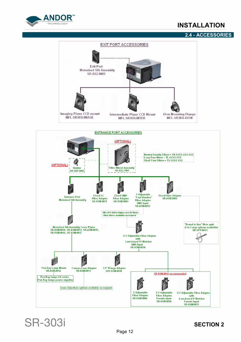
1.6 - COMPONENTS
The main components & accessories of the Andor Shamrock SR-303i system are shown on page 12.
1.7 - SPECIFICATIONS General Czerny-Turner arrangement with imaging toroidal optics
Focal Length 303mm Aperture f/4
Reciprocal Dispersion 2.6nm/mm (nominal)
Wavelength Range 190nm to 10µm (detector dependent) Wavelength Resolution 0.1nm (<0.2nm with 25µm pixel CCD detector)
Wavelength Reproducibility ± 0.05nm Wavelength Accuracy ± 0.2nm
Focal Plane Size 28mm wide x 14mm high Time to switch gratings <10 secs
Stray Light 1.5 x 10⁻⁴
(measured at 20nm from 633nm laser line)
Sizes & Weight
Length 394mm (15.5")
Width 283mm (11.1") Height 208mm (7.9")
Optical Axis Heights 127mm (5") with fixed pad feet 143mm (5.6”) - 173mm (6.8”) with adjustable feet
Weight 20kg (44.1 lb approx)
Slit
Type Motorised, 10µm to 2.5mm Maximum height 14mm (height selectable with interchangeable plates)
Gratings
Size 68mm x 68mm Mount Type Triple grating turret (interchangeable)

INSTALLATION
SR-303i SECTION 2 Page 10
SECTION 2 - INSTALLATION 2.1 - SAFETY PRECAUTIONS
THERE ARE NO USER-SERVICEABLE PARTS INSIDE THE SR-303i. A NUMBER OF SCREWS ON THE
SR-303i HAVE BEEN MARKED WITH RED PAINT TO PREVENT TAMPERING. IF YOU ADJUST THESE
SCREWS YOUR WARRANTY WILL BE VOID.
NOTE: The cover should only be opened when absolutely necessary, i.e. to swap out grating turrets or
other accessories
2.1.1 - Working with Electronics
The computer equipment that is to be used to operate the SR-303i should be fitted with appropriate
surge/EMI/RFI protection on all power lines. Dedicated power lines or line isolation may be required for some
extremely noisy sites.
Appropriate static control procedures should be used during the installation of the system. Attention should be
given to grounding. All cables should be screwed (finger tight only) into place in order to provide a reliable
connection and to prevent accidental disconnection. The power supply to the computer system should be
switched off when changing connections between the computer and the SR-303i. The computer manufacturer's
safety precautions should be followed when installing the Interface Card into the computer.
The circuits used in the SR-303i & the interface Card are extremely sensitive to static electricity and radiated
electromagnetic fields, and therefore they should neither be used nor stored in close proximity to EMI/RFI
generators, electrostatic field generators, electromagnetic or radioactive devices, or other similar sources of
high energy fields. Some examples of equipment which can cause problems are plasma sources, arc welders,
radio frequency generators, X-ray instruments, and pulsed discharge optical sources. Operation of the system
close to intense pulsed sources (lasers, xenon strobes, arc lamps, and the like) may compromise performance
if shielding is inadequate.
NOTE: In the event of extreme power or ESD surges, the software may crash. Should this occur, power
the SR-303i OFF/ON, then restart the software.
2.2 - UNPACKING THE SHAMROCK SR-303i
BEFORE unpacking the SR-303i, allow the shipping box to fully acclimatise to room temperature.
While the SR-303i requires no special placement in a controlled environment it should be noted that it is a
precision instrument that will perform best when set up and operated properly.
Please read this manual carefully before using and always handle with the care accorded to any precision
instrument.

INSTALLATION
SR-303i SECTION 2 Page 11
2.3 - INSTALLING HARDWARE
Carefully remove the SR-303i from its packaging. The following should be included:
• Shamrock SR-303i base unit
• Universal power supply (with relevant lead and plug - country specific)
• Allen Key set comprising 2mm, 2.5mm, 3mm & 5mm keys
• I2C Cable
• USB Cable
• CD containing the SR-303i interface software
• Andor Users guides on CD (Including this manual) and Certificate of Conformance
Depending on the options purchased the following may also be included:
• Andor camera and flange (for connection to the SR-303i)
• Custom flange to connect non-Andor cameras to the SR-303i
• PCI card for connecting the camera to the PC
• PCI or USB 2.0 cable
• Additional PSU (for camera cooling)
INSTALLATION
SR-303i SECTION 2 Page 12
2.4 - ACCESSORIES
INSTALLATION
SR-303i SECTION 2 Page 13
2.5 - USB INSTALLATION
The SR-303i has a USB interface which allows the system to be used as a standalone device, i.e., independent
of an Andor CCD controller card.
To install the USB drivers, firstly connect the USB cable to the computer and to the SR-303i. A Hardware
wizard will then guide the user through the USB drivers’ installation. Several interfaces for this wizard exist,
each performing the same function but presenting it in a slightly different way. Two versions of the wizard are
shown as examples in the next few pages, i.e. Windows 2000 and Windows XP.
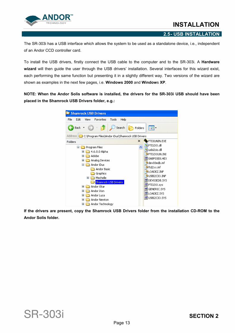
NOTE: When the Andor Solis software is installed, the drivers for the SR-303i USB should have been
placed in the Shamrock USB Drivers folder, e.g.:
If the drivers are present, copy the Shamrock USB Drivers folder from the installation CD-ROM to the
Andor Solis folder.
INSTALLATION
SR-303i SECTION 2 Page 14
2.5.1 - Windows 2000 Hardware Wizard
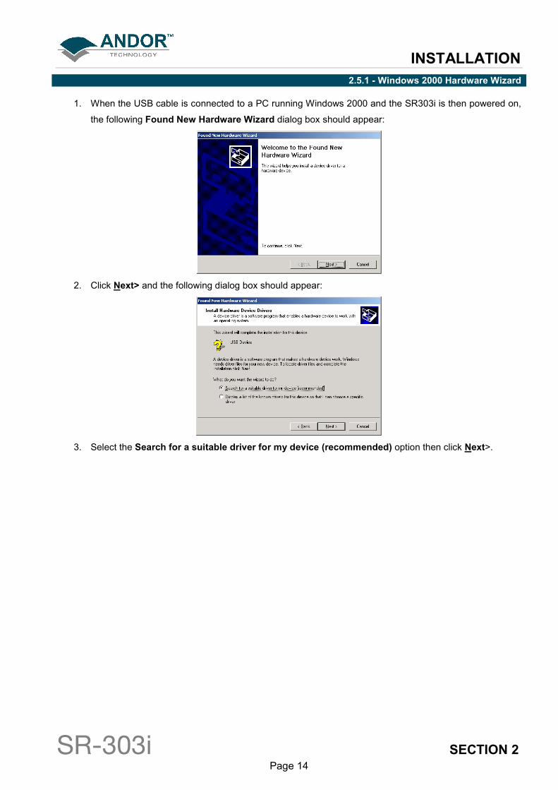
1. When the USB cable is connected to a PC running Windows 2000 and the SR303i is then powered on,
the following Found New Hardware Wizard dialog box should appear:
2. Click Next> and the following dialog box should appear:
3. Select the Search for a suitable driver for my device (recommended) option then click Next>.
INSTALLATION
SR-303i SECTION 2 Page 15
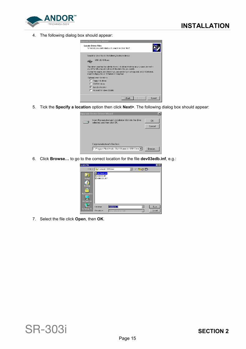
4. The following dialog box should appear:
5. Tick the Specify a location option then click Next>. The following dialog box should appear:
6. Click Browse… to go to the correct location for the file dev03edb.inf, e.g.:
7. Select the file click Open, then OK.

INSTALLATION
SR-303i SECTION 2 Page 16
8. If the driver is successfully located, the following dialog box should appear:
9. Click Next> and the following dialog box should appear:
10. Click Finish to complete the driver installation. You can check that the “DeVaSys” USB device is
recognised by checking system\hardware\device manager via the Control Panel option of the PC.

INSTALLATION
SR-303i SECTION 2 Page 17
2.5.2 - Windows XP Hardware Wizard
1. When the USB cable is connected to a PC running Windows XP and the SR303i is powered on, the
following Found New Hardware Wizard dialog box should appear:
NOTE: If this dialog box does not appear, firstly check that the USB cable is securely connected. If that
is OK then double-click on the “New unknown USB device” icon, e.g. the icon circled in red below:
The dialog box should then appear.
INSTALLATION
SR-303i SECTION 2 Page 18
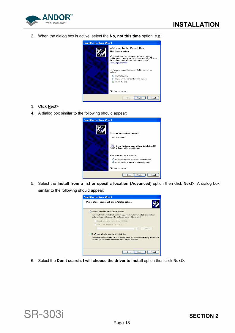
2. When the dialog box is active, select the No, not this time option, e.g.:
3. Click Next>
4. A dialog box similar to the following should appear:
5. Select the Install from a list or specific location (Advanced) option then click Next>. A dialog box
similar to the following should appear:
6. Select the Don’t search. I will choose the driver to install option then click Next>.
INSTALLATION
SR-303i SECTION 2 Page 19
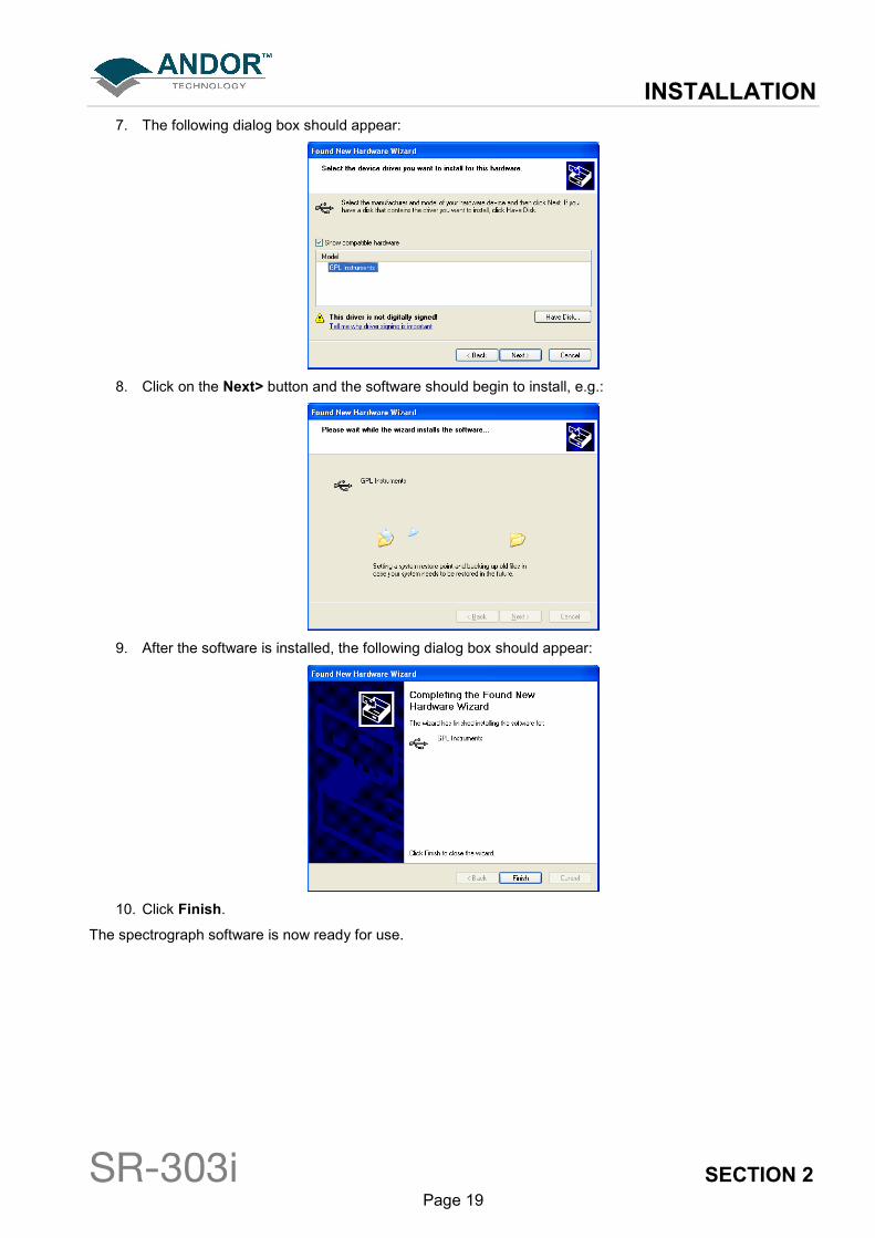
7. The following dialog box should appear:
8. Click on the Next> button and the software should begin to install, e.g.:
9. After the software is installed, the following dialog box should appear:
10. Click Finish.
The spectrograph software is now ready for use.

INSTALLATION
SR-303i SECTION 2 Page 20
2.5.3 - Note on drivers
NOTE 1. If the device is not recognised or the drivers cannot be found despite pointing to the right
folder then:
1. The spectrograph must have been powered on before the computer.
2. The USB cable is not properly connected.
NOTE 2. If you are installing an SR-303i with a serial number less than SR0045 you should take into
account that the USB interface is not “Hot-Plugable”. Before installing the drivers carry out the
following actions:
• Switch off the computer and the Shamrock SR-303i.
• Connect the USB cable to the computer then to the Shamrock SR-303i.
• Switch on the Shamrock SR-303i first then switch on the computer.
Also, SR-303i’s with a serial number less than SR0045 have the following two drivers that need to be installed:
� LOADEZ.INF
� USBI2CIO.INF
So the driver installation process must be done twice, i.e. once per each driver.
INSTALLATION
SR-303i SECTION 2 Page 21
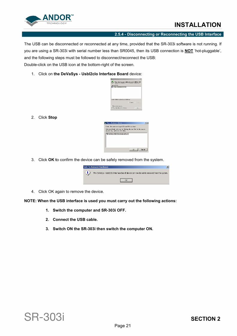
2.5.4 - Disconnecting or Reconnecting the USB Interface
The USB can be disconnected or reconnected at any time, provided that the SR-303i software is not running. If
you are using a SR-303i with serial number less than SR0045, then its USB connection is NOT ‘hot-pluggable’,
and the following steps must be followed to disconnect/reconnect the USB:
Double-click on the USB icon at the bottom-right of the screen.
1. Click on the DeVaSys - UsbI2cIo Interface Board device:
2. Click Stop
3. Click OK to confirm the device can be safely removed from the system.
4. Click OK again to remove the device.
NOTE: When the USB interface is used you must carry out the following actions:
1. Switch the computer and SR-303i OFF.
2. Connect the USB cable.
3. Switch ON the SR-303i then switch the computer ON.

INSTALLATION
SR-303i SECTION 2 Page 22
2.6 - CONNECTING THE CAMERA TO THE SHAMROCK SR-303i
The camera is connected to the SR-303i using the flange supplied with the product. This process varies
depending on whether the user purchased a pre-aligned camera & spectrograph or a “standalone” spectrograph
(i.e. supplied without a camera).
2.6.1 - Pre-aligned Camera & Spectrograph
When a pre-aligned camera & spectrograph package has been purchased the camera comes pre-fitted with a
flange. This flange accurately locates relative to the spectrograph body via precision pins and matching
bushings (please see figure 1 below). These precision pins enable the camera and flange assembly to be
repeatedly attached without the need for any additional calibration, or adjustments, to be made.
Figure 1: Attaching the pre-aligned detector to the SR-303i
To attach the camera, simply insert the alignment pins into the relevant locators and secure in place using the
four M4x123m screws and 3mm Allen key provided. Once connected, no further adjustment is necessary as the
unit is aligned and calibrated at the factory.
INSTALLATION
SR-303i SECTION 2 Page 23
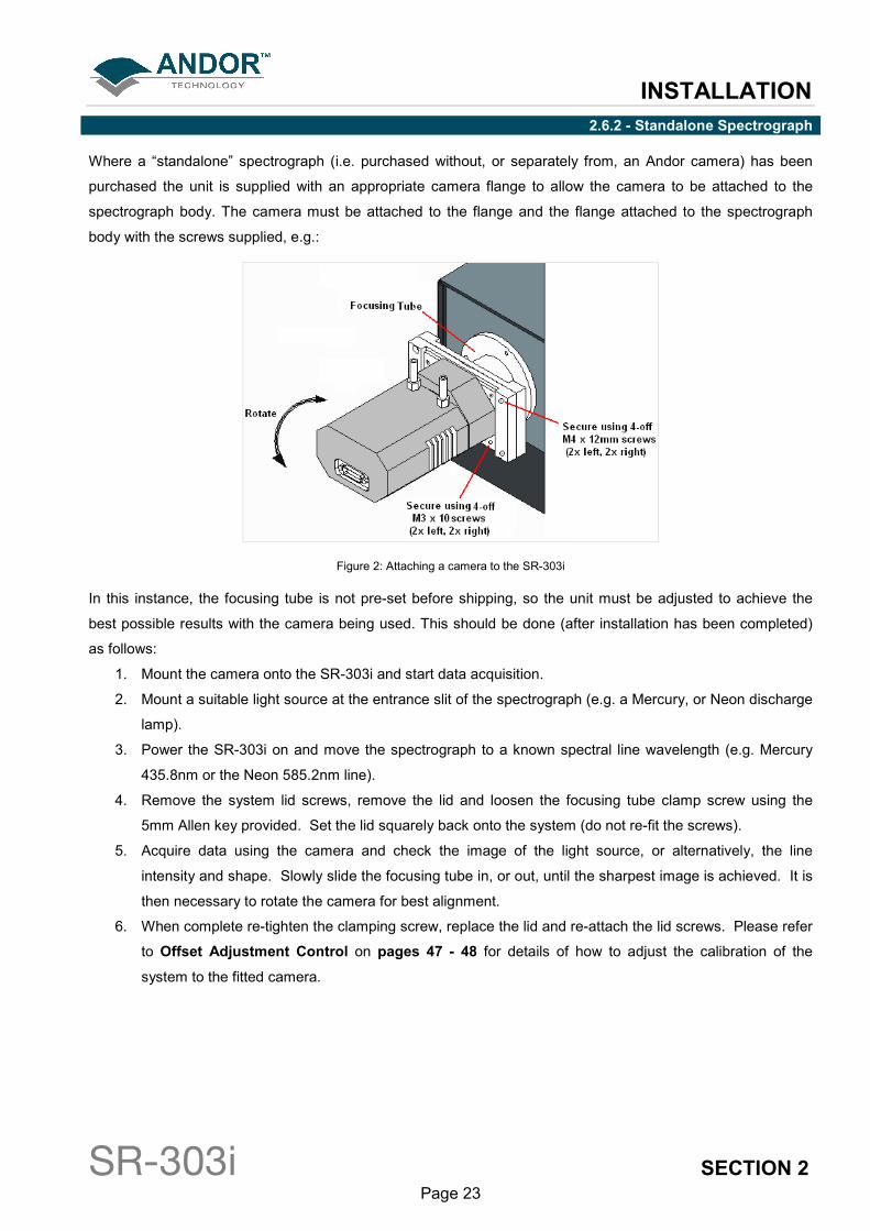
2.6.2 - Standalone Spectrograph
Where a “standalone” spectrograph (i.e. purchased without, or separately from, an Andor camera) has been
purchased the unit is supplied with an appropriate camera flange to allow the camera to be attached to the
spectrograph body. The camera must be attached to the flange and the flange attached to the spectrograph
body with the screws supplied, e.g.:
Figure 2: Attaching a camera to the SR-303i
In this instance, the focusing tube is not pre-set before shipping, so the unit must be adjusted to achieve the
best possible results with the camera being used. This should be done (after installation has been completed)
as follows:
1. Mount the camera onto the SR-303i and start data acquisition.
2. Mount a suitable light source at the entrance slit of the spectrograph (e.g. a Mercury, or Neon discharge
lamp).
3. Power the SR-303i on and move the spectrograph to a known spectral line wavelength (e.g. Mercury
435.8nm or the Neon 585.2nm line).
4. Remove the system lid screws, remove the lid and loosen the focusing tube clamp screw using the
5mm Allen key provided. Set the lid squarely back onto the system (do not re-fit the screws).
5. Acquire data using the camera and check the image of the light source, or alternatively, the line
intensity and shape. Slowly slide the focusing tube in, or out, until the sharpest image is achieved. It is
then necessary to rotate the camera for best alignment.
6. When complete re-tighten the clamping screw, replace the lid and re-attach the lid screws. Please refer
to Offset Adjustment Control on pages 47 - 48 for details of how to adjust the calibration of the
system to the fitted camera.

INSTALLATION
SR-303i SECTION 2 Page 24
2.7 - ANDOR PCI CARD SYSTEMS
Figure 3 illustrates the connection details for a standard Andor PCI CCD camera. The PCI Controller Card
should be installed as you would other slot-in cards, such as graphic or parallel printer adapter cards. Please
consult the manual supplied with your PC to ensure correct installation of the Controller Card for your
particular PC. Please note that with PCI cards, there are no jumpers for you to set.
Figure 3: Hardware connections (PCI card CCD systems)
The general procedure for installing the card is as follows (for more detail refer to the specific camera manual):
• Exit the computer’s operating system and switch off the computer and any peripherals. Fit the supplied
anti-static wristband. Remove the cover of the computer.
• While observing appropriate static control procedures, firmly press the connector on the long edge of
the card into the chosen expansion slot, so that the card’s metal mounting bracket (located at the end of
the card and bearing the connectors for the camera and the multiple I/O adapter) is next to the opening
on the back panel of the computer.
• Ensure the card’s mounting bracket is flush with any other mounting brackets or filler brackets to either
side of it. Use the screw removed from the filler bracket earlier to secure the Controller Card in place.
• Replace the cover of the computer and secure it with the mounting screws.
NOTE: Some Andor cameras have an I2C interface connector fitted. In these cases the I
2C interface
cable illustrated above may be replaced by an optional shorter I2C cable that runs from the camera to
the SR-303i.
INSTALLATION
SR-303i SECTION 2 Page 25
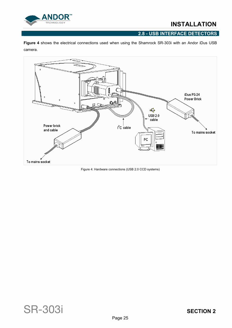
2.8 - USB INTERFACE DETECTORS
Figure 4 shows the electrical connections used when using the Shamrock SR-303i with an Andor iDus USB
camera.
Figure 4: Hardware connections (USB 2.0 CCD systems)
INSTALLATION
SR-303i SECTION 2 Page 26
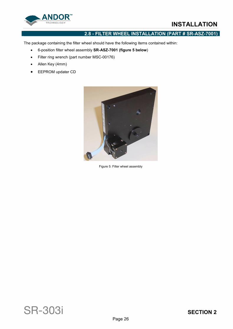
2.8 - FILTER WHEEL INSTALLATION (PART # SR-ASZ-7001)
The package containing the filter wheel should have the following items contained within:
• 6-position filter wheel assembly SR-ASZ-7001 (figure 5 below)
• Filter ring wrench (part number MSC-00176)
• Allen Key (4mm)
• EEPROM updater CD
Figure 5: Filter wheel assembly
INSTALLATION
SR-303i SECTION 2 Page 27
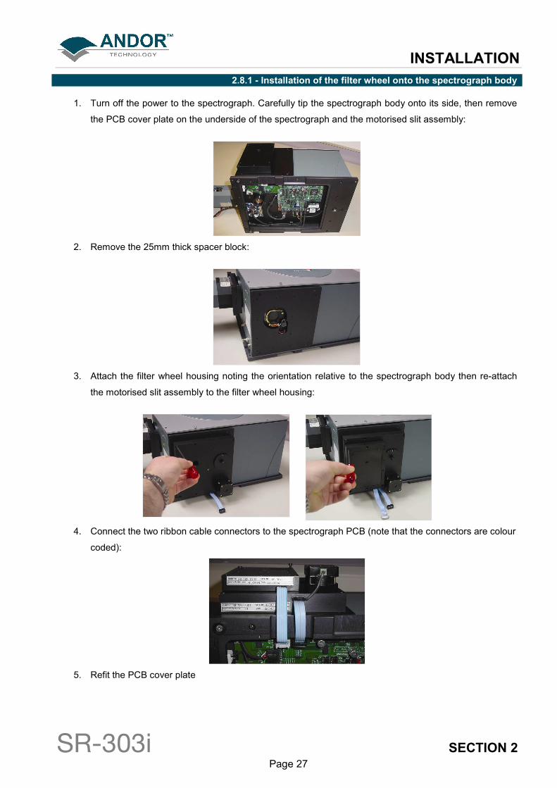
2.8.1 - Installation of the filter wheel onto the spectrograph body
1. Turn off the power to the spectrograph. Carefully tip the spectrograph body onto its side, then remove
the PCB cover plate on the underside of the spectrograph and the motorised slit assembly:
2. Remove the 25mm thick spacer block:
3. Attach the filter wheel housing noting the orientation relative to the spectrograph body then re-attach
the motorised slit assembly to the filter wheel housing:
4. Connect the two ribbon cable connectors to the spectrograph PCB (note that the connectors are colour
coded):
5. Refit the PCB cover plate
INSTALLATION
SR-303i SECTION 2 Page 28
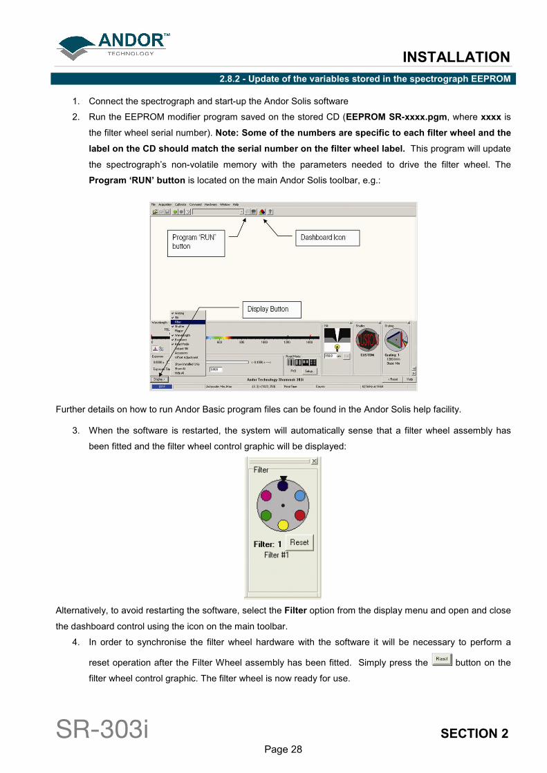
2.8.2 - Update of the variables stored in the spectrograph EEPROM
1. Connect the spectrograph and start-up the Andor Solis software
2. Run the EEPROM modifier program saved on the stored CD (EEPROM SR-xxxx.pgm, where xxxx is
the filter wheel serial number). Note: Some of the numbers are specific to each filter wheel and the
label on the CD should match the serial number on the filter wheel label. This program will update
the spectrograph’s non-volatile memory with the parameters needed to drive the filter wheel. The
Program ‘RUN’ button is located on the main Andor Solis toolbar, e.g.:
Further details on how to run Andor Basic program files can be found in the Andor Solis help facility.
3. When the software is restarted, the system will automatically sense that a filter wheel assembly has
been fitted and the filter wheel control graphic will be displayed:
Alternatively, to avoid restarting the software, select the Filter option from the display menu and open and close
the dashboard control using the icon on the main toolbar.
4. In order to synchronise the filter wheel hardware with the software it will be necessary to perform a
reset operation after the Filter Wheel assembly has been fitted. Simply press the button on the
filter wheel control graphic. The filter wheel is now ready for use.

INSTALLATION
SR-303i SECTION 2 Page 29
2.9 - INSTALLATION OF FILTERS
Filters may be added, removed or replaced in the filter wheel in two ways:
• Option 1: by the complete removal of the filter wheel from the filter wheel housing
• Option 2: via the filter access hole on the front face of the filter wheel housing
2.9.1 - Option 1
Option 1 may be found to be more convenient when a large number of filters are to be added at the same time,
or prior to the initial installation of the filter wheel assembly onto the spectrograph body.
1. Remove the filter assembly from the spectrograph in the reverse of the procedure shown on page 27.
Alternatively, remove the four (M4 x 25mm) cap head screws securing the filter wheel to the
spectrograph body and carefully allow the filter wheel and motorised slits to fall forward:
2. The filter wheel has been designed to allow the filter wheel to be removed from the filter wheel
assembly housing with the removal of one screw. Unscrew the M5 x 16mm stainless steel Allen bolt
from the middle of the filter wheel using a 3mm Allen key and withdraw the wheel from the housing:
3. The filters may now be inserted into the filter wheel. Use the supplied filter ring wrench to first remove
and then tighten the 1” filter retaining rings:
4. Remember to take a note of the filter details and the filter number where it has been fitted. These
details will be required to update the filter details stored in the spectrographs non-volatile memory (see
page 20). Re-attach the filter wheel in to the filter housing.

INSTALLATION
SR-303i SECTION 2 Page 30
2.9.2 - Option 2
Access to the filters may also be gained via the filter access hole located on the front face of the filter wheel.
1. Remove the magnetic filter wheel access cover by gently pulling it, i.e.:
2. The filter position ID number will now be visible, e.g.:
NOTE: The filter position accessible via the access hole has an ID number 2 less than the filter position
in the optical path, and the number displayed in the software (e.g. filter position 2) will be accessible via
the access hole when filter position 4 has been selected in the software (i.e. 2 →→→→ 4).
Similarly, 3 →→→→ 5, 4 →→→→ 6,5 →→→→ 1, 6 →→→→ 2, 1→→→→ 3.
3. Using the software select the filter position needed to bring the required filter position into place.
2.9.3 - Initialising the filter wheel
After fitting, or replacing filters, it is good practice to synchronise the filter wheel hardware with the software
interface.
Simply press the button on the filter wheel control graphic.
INSTALLATION
SR-303i SECTION 2 Page 31
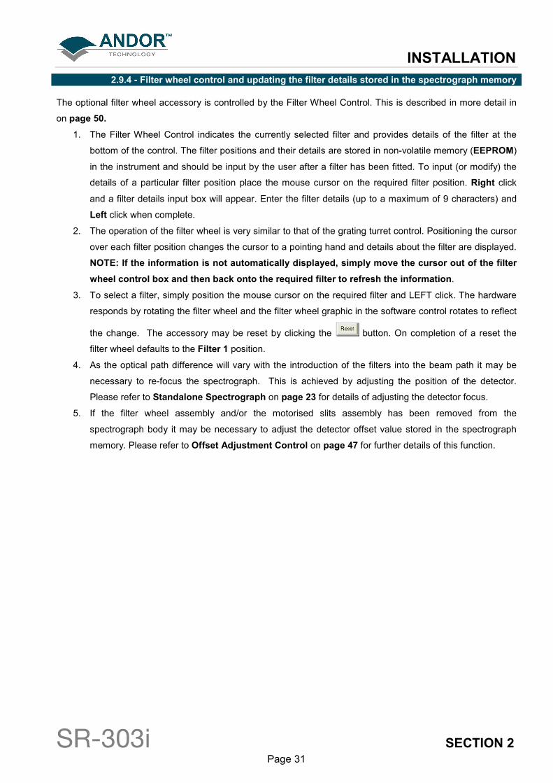
2.9.4 - Filter wheel control and updating the filter details stored in the spectrograph memory
The optional filter wheel accessory is controlled by the Filter Wheel Control. This is described in more detail in
on page 50.
1. The Filter Wheel Control indicates the currently selected filter and provides details of the filter at the
bottom of the control. The filter positions and their details are stored in non-volatile memory (EEPROM)
in the instrument and should be input by the user after a filter has been fitted. To input (or modify) the
details of a particular filter position place the mouse cursor on the required filter position. Right click
and a filter details input box will appear. Enter the filter details (up to a maximum of 9 characters) and
Left click when complete.
2. The operation of the filter wheel is very similar to that of the grating turret control. Positioning the cursor
over each filter position changes the cursor to a pointing hand and details about the filter are displayed.
NOTE: If the information is not automatically displayed, simply move the cursor out of the filter
wheel control box and then back onto the required filter to refresh the information.
3. To select a filter, simply position the mouse cursor on the required filter and LEFT click. The hardware
responds by rotating the filter wheel and the filter wheel graphic in the software control rotates to reflect
the change. The accessory may be reset by clicking the button. On completion of a reset the
filter wheel defaults to the Filter 1 position.
4. As the optical path difference will vary with the introduction of the filters into the beam path it may be
necessary to re-focus the spectrograph. This is achieved by adjusting the position of the detector.
Please refer to Standalone Spectrograph on page 23 for details of adjusting the detector focus.
5. If the filter wheel assembly and/or the motorised slits assembly has been removed from the
spectrograph body it may be necessary to adjust the detector offset value stored in the spectrograph
memory. Please refer to Offset Adjustment Control on page 47 for further details of this function.
INSTALLATION
SR-303i SECTION 2 Page 32
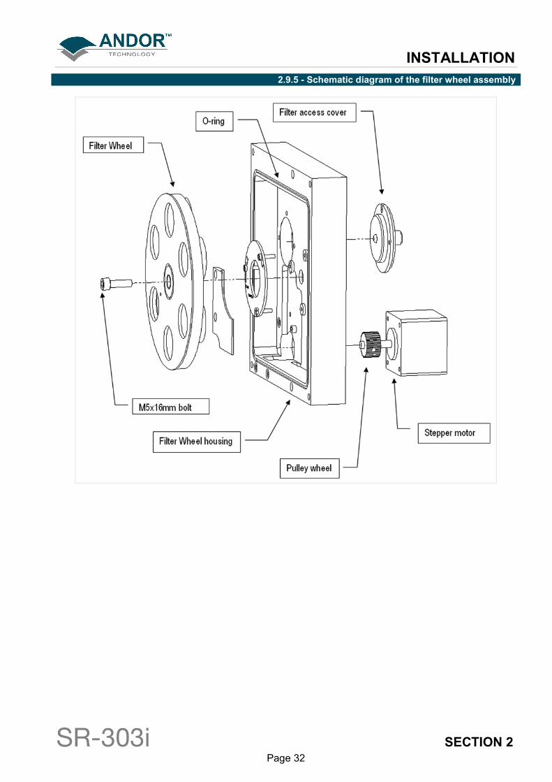
2.9.5 - Schematic diagram of the filter wheel assembly

INSTALLATION
SR-303i SECTION 2 Page 33
2.9.6 - Dimensions & specification of the 6-position filter wheel assembly (part # SR-ASZ-7001)
Specifications
Filter Size 1”
Maximum number of filters 6
Maximum filter thickness 8mm
Maximum time between filter changes 2 secs
OPERATION
SR-303i SECTION 3 Page 34
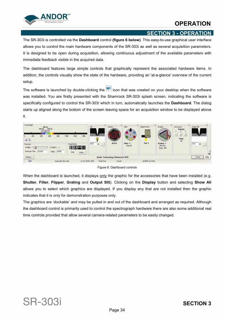
SECTION 3 - OPERATION The SR-303i is controlled via the Dashboard control (figure 6 below). This easy-to-use graphical user interface
allows you to control the main hardware components of the SR-303i as well as several acquisition parameters.
It is designed to be open during acquisition, allowing continuous adjustment of the available parameters with
immediate feedback visible in the acquired data.
The dashboard features large simple controls that graphically represent the associated hardware items. In
addition, the controls visually show the state of the hardware, providing an 'at-a-glance' overview of the current
setup.
The software is launched by double-clicking the icon that was created on your desktop when the software
was installed. You are firstly presented with the Shamrock SR-303i splash screen, indicating the software is
specifically configured to control the SR-303i which in turn, automatically launches the Dashboard. The dialog
starts up aligned along the bottom of the screen leaving space for an acquisition window to be displayed above
it.
Figure 6: Dashboard controls
When the dashboard is launched, it displays only the graphic for the accessories that have been installed (e.g.
Shutter, Filter, Flipper, Grating and Output Slit). Clicking on the Display button and selecting Show All
allows you to select which graphics are displayed. If you display any that are not installed then the graphic
indicates that it is only for demonstration purposes only.
The graphics are ‘dockable’ and may be pulled in and out of the dashboard and arranged as required. Although
the dashboard control is primarily used to control the spectrograph hardware there are also some additional real
time controls provided that allow several camera-related parameters to be easily changed.
OPERATION
SR-303i SECTION 3 Page 35
3.1 - DETECTOR CONTROLS
The following paragraphs describe the basic camera controls incorporated on the Dashboard control. For more
detailed descriptions of these parameters and other available adjustments please refer to the supplied camera
manual.
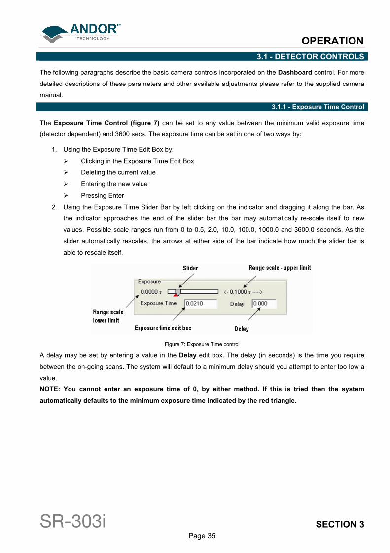
3.1.1 - Exposure Time Control
The Exposure Time Control (figure 7) can be set to any value between the minimum valid exposure time
(detector dependent) and 3600 secs. The exposure time can be set in one of two ways by:
1. Using the Exposure Time Edit Box by:
� Clicking in the Exposure Time Edit Box
� Deleting the current value
� Entering the new value
� Pressing Enter
2. Using the Exposure Time Slider Bar by left clicking on the indicator and dragging it along the bar. As
the indicator approaches the end of the slider bar the bar may automatically re-scale itself to new
values. Possible scale ranges run from 0 to 0.5, 2.0, 10.0, 100.0, 1000.0 and 3600.0 seconds. As the
slider automatically rescales, the arrows at either side of the bar indicate how much the slider bar is
able to rescale itself.
Figure 7: Exposure Time control
A delay may be set by entering a value in the Delay edit box. The delay (in seconds) is the time you require
between the on-going scans. The system will default to a minimum delay should you attempt to enter too low a
value.
NOTE: You cannot enter an exposure time of 0, by either method. If this is tried then the system
automatically defaults to the minimum exposure time indicated by the red triangle.
OPERATION
SR-303i SECTION 3 Page 36
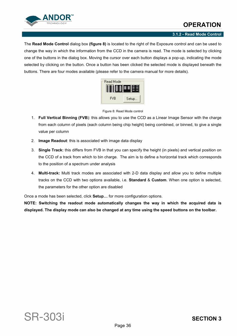
3.1.2 - Read Mode Control
The Read Mode Control dialog box (figure 8) is located to the right of the Exposure control and can be used to
change the way in which the information from the CCD in the camera is read. The mode is selected by clicking
one of the buttons in the dialog box. Moving the cursor over each button displays a pop-up, indicating the mode
selected by clicking on the button. Once a button has been clicked the selected mode is displayed beneath the
buttons. There are four modes available (please refer to the camera manual for more details).
Figure 8: Read Mode control
1. Full Vertical Binning (FVB): this allows you to use the CCD as a Linear Image Sensor with the charge
from each column of pixels (each column being chip height) being combined, or binned, to give a single
value per column
2. Image Readout: this is associated with image data display
3. Single Track: this differs from FVB in that you can specify the height (in pixels) and vertical position on
the CCD of a track from which to bin charge. The aim is to define a horizontal track which corresponds
to the position of a spectrum under analysis
4. Multi-track: Multi track modes are associated with 2-D data display and allow you to define multiple
tracks on the CCD with two options available, i.e. Standard & Custom. When one option is selected,
the parameters for the other option are disabled
Once a mode has been selected, click Setup… for more configuration options.
NOTE: Switching the readout mode automatically changes the way in which the acquired data is
displayed. The display mode can also be changed at any time using the speed buttons on the toolbar.
OPERATION
SR-303i SECTION 3 Page 37
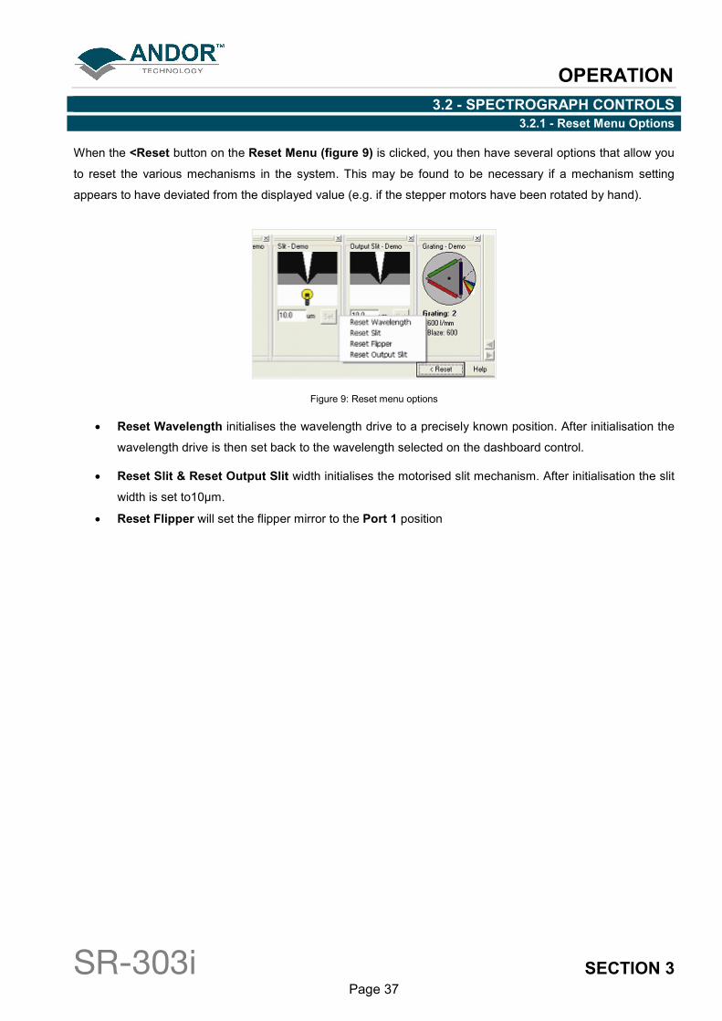
3.2 - SPECTROGRAPH CONTROLS 3.2.1 - Reset Menu Options
When the <Reset button on the Reset Menu (figure 9) is clicked, you then have several options that allow you
to reset the various mechanisms in the system. This may be found to be necessary if a mechanism setting
appears to have deviated from the displayed value (e.g. if the stepper motors have been rotated by hand).
Figure 9: Reset menu options
• Reset Wavelength initialises the wavelength drive to a precisely known position. After initialisation the
wavelength drive is then set back to the wavelength selected on the dashboard control.
• Reset Slit & Reset Output Slit width initialises the motorised slit mechanism. After initialisation the slit
width is set to10µm.
• Reset Flipper will set the flipper mirror to the Port 1 position
OPERATION
SR-303i SECTION 3 Page 38
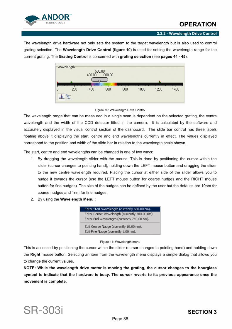
3.2.2 - Wavelength Drive Control
The wavelength drive hardware not only sets the system to the target wavelength but is also used to control
grating selection. The Wavelength Drive Control (figure 10) is used for setting the wavelength range for the
current grating. The Grating Control is concerned with grating selection (see pages 44 - 45).
Figure 10: Wavelength Drive Control
The wavelength range that can be measured in a single scan is dependent on the selected grating, the centre
wavelength and the width of the CCD detector fitted in the camera. It is calculated by the software and
accurately displayed in the visual control section of the dashboard. The slide bar control has three labels
floating above it displaying the start, centre and end wavelengths currently in effect. The values displayed
correspond to the position and width of the slide bar in relation to the wavelength scale shown.
The start, centre and end wavelengths can be changed in one of two ways:
1. By dragging the wavelength slider with the mouse. This is done by positioning the cursor within the
slider (cursor changes to pointing hand), holding down the LEFT mouse button and dragging the slider
to the new centre wavelength required. Placing the cursor at either side of the slider allows you to
nudge it towards the cursor (use the LEFT mouse button for coarse nudges and the RIGHT mouse
button for fine nudges). The size of the nudges can be defined by the user but the defaults are 10nm for
course nudges and 1nm for fine nudges.
2. By using the Wavelength Menu :
Figure 11: Wavelength menu
This is accessed by positioning the cursor within the slider (cursor changes to pointing hand) and holding down
the Right mouse button. Selecting an item from the wavelength menu displays a simple dialog that allows you
to change the current values.
NOTE: While the wavelength drive motor is moving the grating, the cursor changes to the hourglass
symbol to indicate that the hardware is busy. The cursor reverts to its previous appearance once the
movement is complete.
OPERATION
SR-303i SECTION 3 Page 39
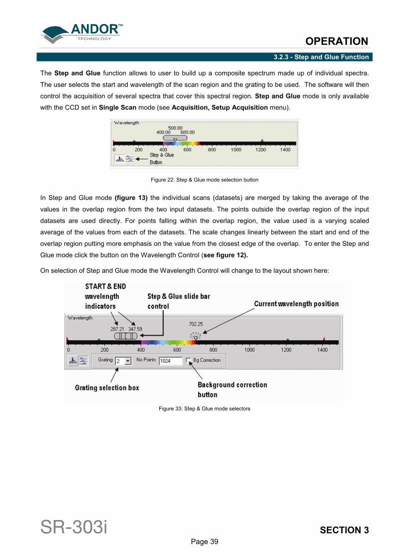
3.2.3 - Step and Glue Function
The Step and Glue function allows to user to build up a composite spectrum made up of individual spectra.
The user selects the start and wavelength of the scan region and the grating to be used. The software will then
control the acquisition of several spectra that cover this spectral region. Step and Glue mode is only available
with the CCD set in Single Scan mode (see Acquisition, Setup Acquisition menu).
Figure 22: Step & Glue mode selection button
In Step and Glue mode (figure 13) the individual scans (datasets) are merged by taking the average of the
values in the overlap region from the two input datasets. The points outside the overlap region of the input
datasets are used directly. For points falling within the overlap region, the value used is a varying scaled
average of the values from each of the datasets. The scale changes linearly between the start and end of the
overlap region putting more emphasis on the value from the closest edge of the overlap. To enter the Step and
Glue mode click the button on the Wavelength Control (see figure 12).
On selection of Step and Glue mode the Wavelength Control will change to the layout shown here:
Figure 33: Step & Glue mode selectors
OPERATION
SR-303i SECTION 3 Page 40
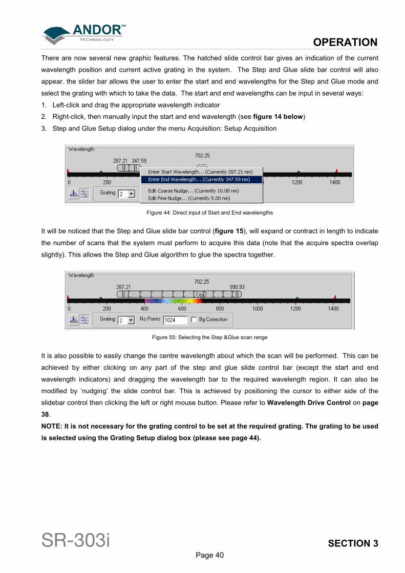
There are now several new graphic features. The hatched slide control bar gives an indication of the current
wavelength position and current active grating in the system. The Step and Glue slide bar control will also
appear. the slider bar allows the user to enter the start and end wavelengths for the Step and Glue mode and
select the grating with which to take the data. The start and end wavelengths can be input in several ways:
1. Left-click and drag the appropriate wavelength indicator
2. Right-click, then manually input the start and end wavelength (see figure 14 below)
3. Step and Glue Setup dialog under the menu Acquisition: Setup Acquisition
Figure 44: Direct input of Start and End wavelengths
It will be noticed that the Step and Glue slide bar control (figure 15), will expand or contract in length to indicate
the number of scans that the system must perform to acquire this data (note that the acquire spectra overlap
slightly). This allows the Step and Glue algorithm to glue the spectra together.
Figure 55: Selecting the Step &Glue scan range
It is also possible to easily change the centre wavelength about which the scan will be performed. This can be
achieved by either clicking on any part of the step and glue slide control bar (except the start and end
wavelength indicators) and dragging the wavelength bar to the required wavelength region. It can also be
modified by ‘nudging’ the slide control bar. This is achieved by positioning the cursor to either side of the
slidebar control then clicking the left or right mouse button. Please refer to Wavelength Drive Control on page
38.
NOTE: It is not necessary for the grating control to be set at the required grating. The grating to be used
is selected using the Grating Setup dialog box (please see page 44).
OPERATION
SR-303i SECTION 3 Page 41
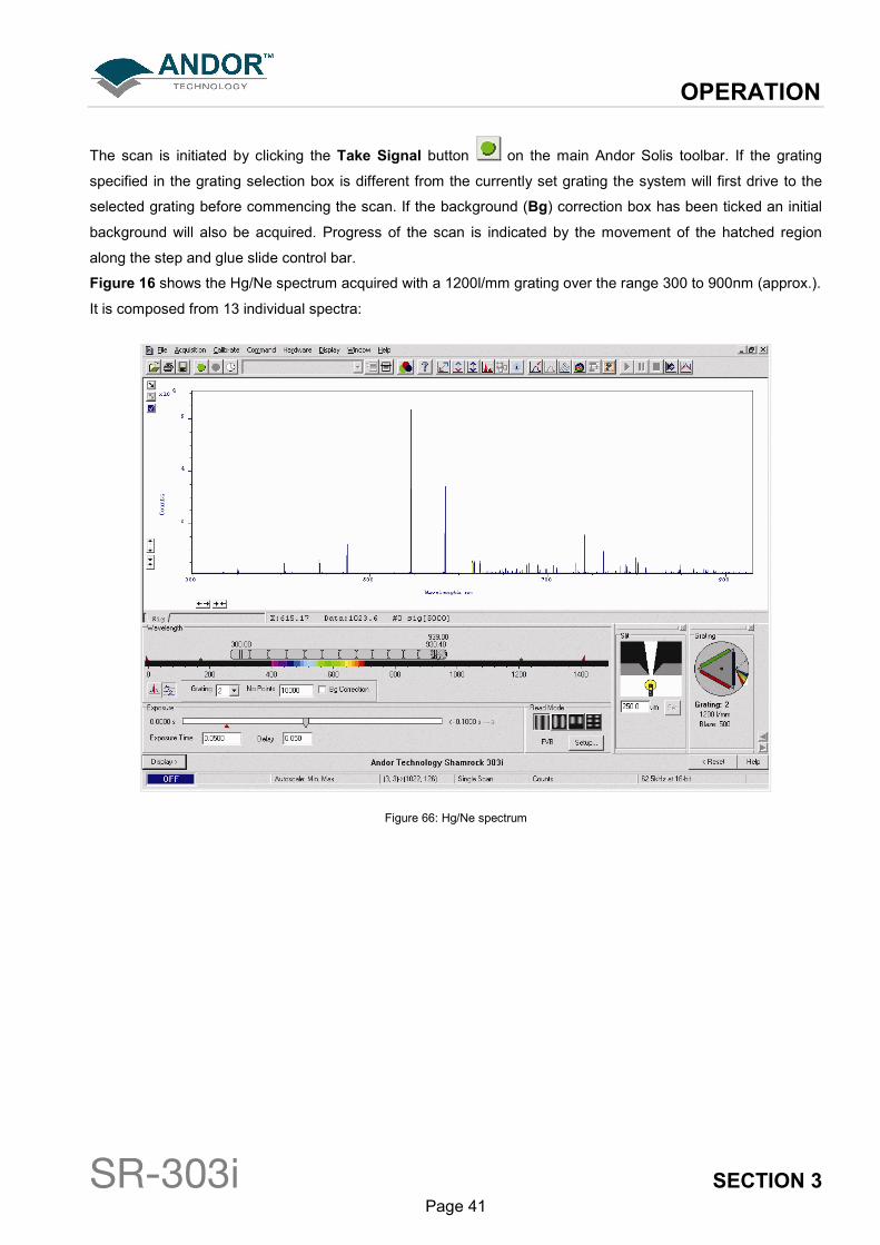
The scan is initiated by clicking the Take Signal button on the main Andor Solis toolbar. If the grating
specified in the grating selection box is different from the currently set grating the system will first drive to the
selected grating before commencing the scan. If the background (Bg) correction box has been ticked an initial
background will also be acquired. Progress of the scan is indicated by the movement of the hatched region
along the step and glue slide control bar.
Figure 16 shows the Hg/Ne spectrum acquired with a 1200l/mm grating over the range 300 to 900nm (approx.).
It is composed from 13 individual spectra:
Figure 66: Hg/Ne spectrum
OPERATION
SR-303i SECTION 3 Page 42
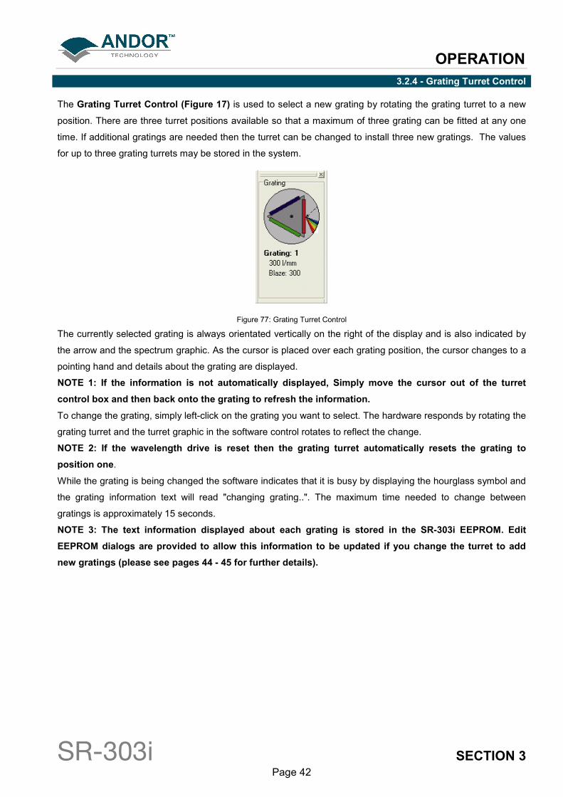
3.2.4 - Grating Turret Control
The Grating Turret Control (Figure 17) is used to select a new grating by rotating the grating turret to a new
position. There are three turret positions available so that a maximum of three grating can be fitted at any one
time. If additional gratings are needed then the turret can be changed to install three new gratings. The values
for up to three grating turrets may be stored in the system.
Figure 77: Grating Turret Control
The currently selected grating is always orientated vertically on the right of the display and is also indicated by
the arrow and the spectrum graphic. As the cursor is placed over each grating position, the cursor changes to a
pointing hand and details about the grating are displayed.
NOTE 1: If the information is not automatically displayed, Simply move the cursor out of the turret
control box and then back onto the grating to refresh the information.
To change the grating, simply left-click on the grating you want to select. The hardware responds by rotating the
grating turret and the turret graphic in the software control rotates to reflect the change.
NOTE 2: If the wavelength drive is reset then the grating turret automatically resets the grating to
position one.
While the grating is being changed the software indicates that it is busy by displaying the hourglass symbol and
the grating information text will read "changing grating..". The maximum time needed to change between
gratings is approximately 15 seconds.
NOTE 3: The text information displayed about each grating is stored in the SR-303i EEPROM. Edit
EEPROM dialogs are provided to allow this information to be updated if you change the turret to add
new gratings (please see pages 44 - 45 for further details).
OPERATION
SR-303i SECTION 3 Page 43
3.3 - REMOVING & REPLACING THE GRATING TURRET
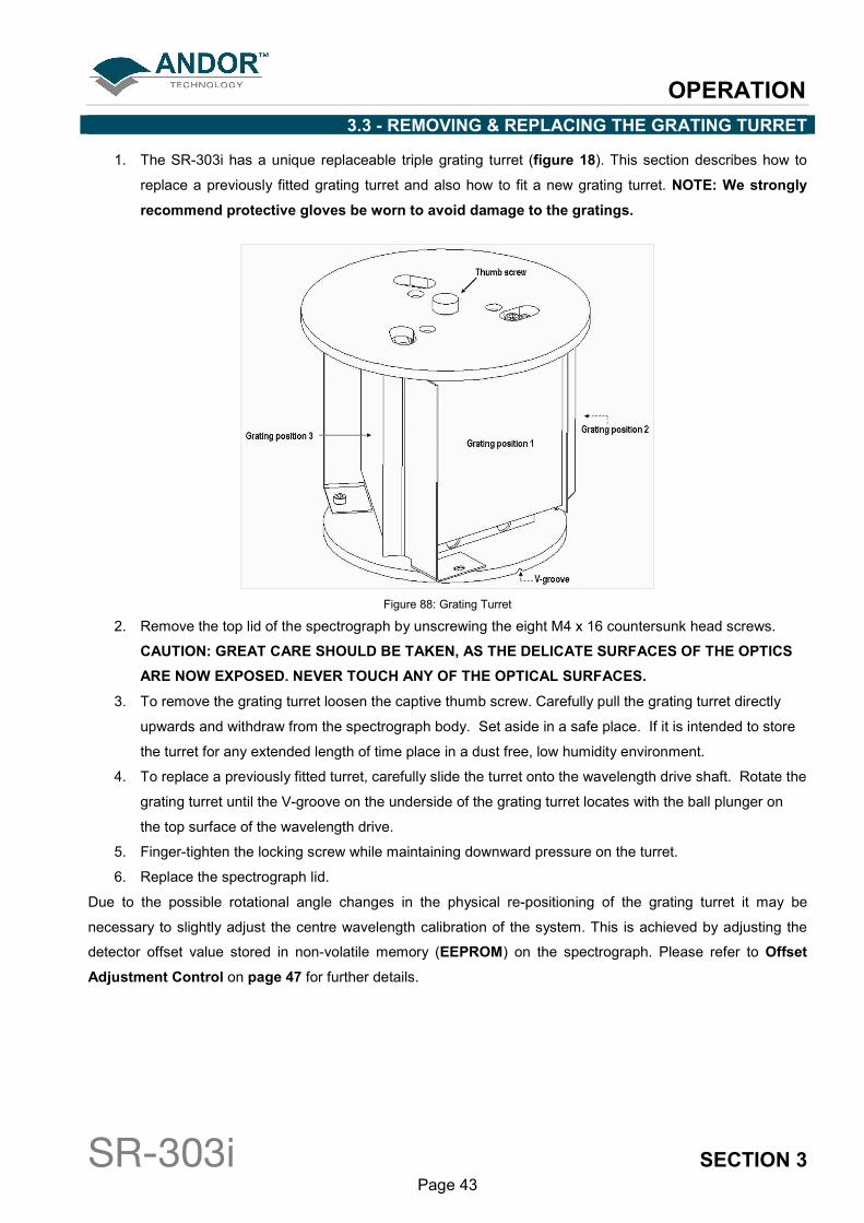
1. The SR-303i has a unique replaceable triple grating turret (figure 18). This section describes how to
replace a previously fitted grating turret and also how to fit a new grating turret. NOTE: We strongly
recommend protective gloves be worn to avoid damage to the gratings.
Figure 88: Grating Turret
2. Remove the top lid of the spectrograph by unscrewing the eight M4 x 16 countersunk head screws.
CAUTION: GREAT CARE SHOULD BE TAKEN, AS THE DELICATE SURFACES OF THE OPTICS
ARE NOW EXPOSED. NEVER TOUCH ANY OF THE OPTICAL SURFACES.
3. To remove the grating turret loosen the captive thumb screw. Carefully pull the grating turret directly
upwards and withdraw from the spectrograph body. Set aside in a safe place. If it is intended to store
the turret for any extended length of time place in a dust free, low humidity environment.
4. To replace a previously fitted turret, carefully slide the turret onto the wavelength drive shaft. Rotate the
grating turret until the V-groove on the underside of the grating turret locates with the ball plunger on
the top surface of the wavelength drive.
5. Finger-tighten the locking screw while maintaining downward pressure on the turret.
6. Replace the spectrograph lid.
Due to the possible rotational angle changes in the physical re-positioning of the grating turret it may be
necessary to slightly adjust the centre wavelength calibration of the system. This is achieved by adjusting the
detector offset value stored in non-volatile memory (EEPROM) on the spectrograph. Please refer to Offset
Adjustment Control on page 47 for further details.
OPERATION
SR-303i SECTION 3 Page 44
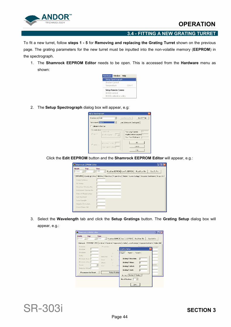
3.4 - FITTING A NEW GRATING TURRET
To fit a new turret, follow steps 1 - 5 for Removing and replacing the Grating Turret shown on the previous
page. The grating parameters for the new turret must be inputted into the non-volatile memory (EEPROM) in
the spectrograph.
1. The Shamrock EEPROM Editor needs to be open. This is accessed from the Hardware menu as
shown:
2. The Setup Spectrograph dialog box will appear, e.g:
Click the Edit EEPROM button and the Shamrock EEPROM Editor will appear, e.g.:
3. Select the Wavelength tab and click the Setup Gratings button. The Grating Setup dialog box will
appear, e.g.:
OPERATION
SR-303i SECTION 3 Page 45
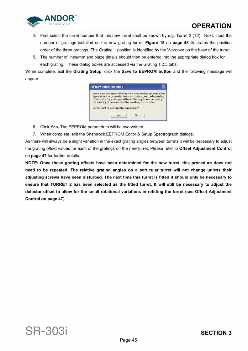
4. First select the turret number that this new turret shall be known by e.g. Turret 2 (T2). Next, input the
number of gratings installed on the new grating turret. Figure 18 on page 43 illustrates the position
order of the three gratings. The Grating 1 position is identified by the V-groove on the base of the turret.
5. The number of lines/mm and blaze details should then be entered into the appropriate dialog box for
each grating. These dialog boxes are accessed via the Grating 1,2,3 tabs.
When complete, exit the Grating Setup, click the Save to EEPROM button and the following message will
appear:
6. Click Yes. The EEPROM parameters will be overwritten.
7. When complete, exit the Shamrock EEPROM Editor & Setup Spectrograph dialogs.
As there will always be a slight variation in the exact grating angles between turrets it will be necessary to adjust
the grating offset values for each of the gratings on the new turret. Please refer to Offset Adjustment Control
on page 47 for further details.
NOTE: Once these grating offsets have been determined for the new turret, this procedure does not
need to be repeated. The relative grating angles on a particular turret will not change unless their
adjusting screws have been disturbed. The next time this turret is fitted it should only be necessary to
ensure that TURRET 2 has been selected as the fitted turret. It will still be necessary to adjust the
detector offset to allow for the small rotational variations in refitting the turret (see Offset Adjustment
Control on page 47).
OPERATION
SR-303i SECTION 3 Page 46
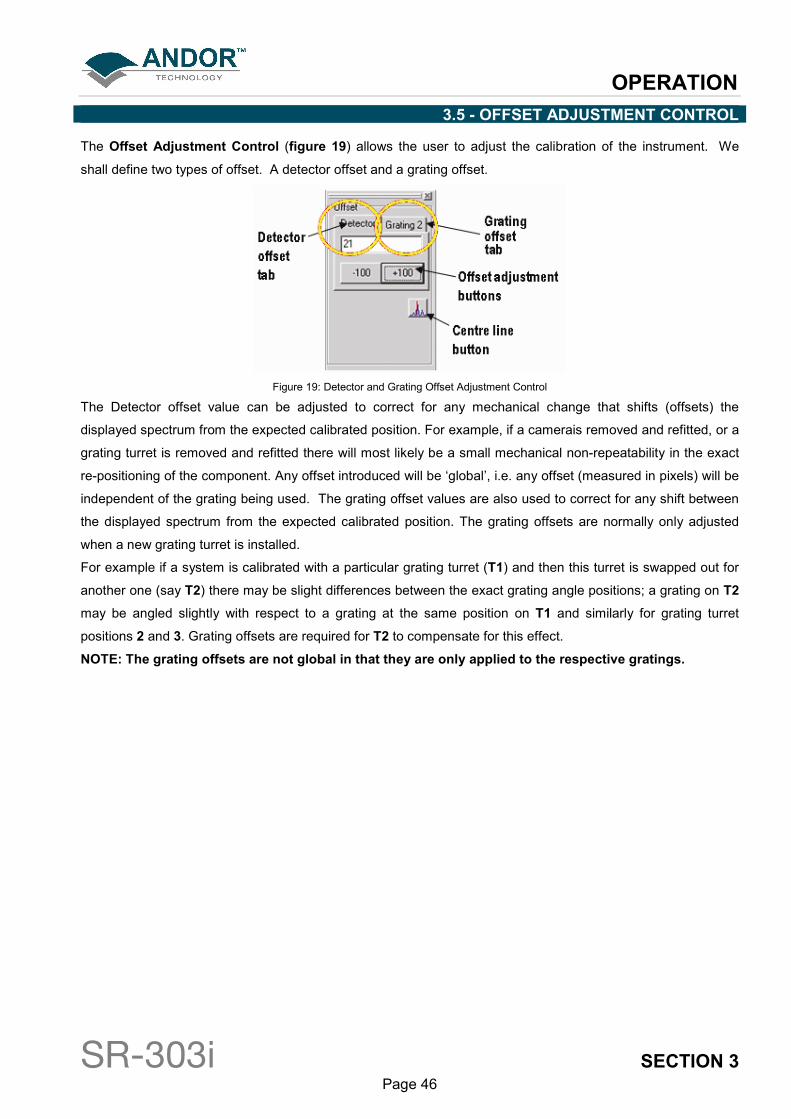
3.5 - OFFSET ADJUSTMENT CONTROL
The Offset Adjustment Control (figure 19) allows the user to adjust the calibration of the instrument. We
shall define two types of offset. A detector offset and a grating offset.
Figure 19: Detector and Grating Offset Adjustment Control
The Detector offset value can be adjusted to correct for any mechanical change that shifts (offsets) the
displayed spectrum from the expected calibrated position. For example, if a camerais removed and refitted, or a
grating turret is removed and refitted there will most likely be a small mechanical non-repeatability in the exact
re-positioning of the component. Any offset introduced will be ‘global’, i.e. any offset (measured in pixels) will be
independent of the grating being used. The grating offset values are also used to correct for any shift between
the displayed spectrum from the expected calibrated position. The grating offsets are normally only adjusted
when a new grating turret is installed.
For example if a system is calibrated with a particular grating turret (T1) and then this turret is swapped out for
another one (say T2) there may be slight differences between the exact grating angle positions; a grating on T2
may be angled slightly with respect to a grating at the same position on T1 and similarly for grating turret
positions 2 and 3. Grating offsets are required for T2 to compensate for this effect.
NOTE: The grating offsets are not global in that they are only applied to the respective gratings.
OPERATION
SR-303i SECTION 3 Page 47
3.5.1 - Offset Adjustment Procedure
Detector or grating offset adjustment is selected via the tabs on the Offset Adjustment Control. The following
describes the procedure for the detector offset adjustment but the grating offset adjustments are performed in
the same manner.
1. If the offset adjustment control is not already displayed press the Display button and select the offset
adjustment control. Click the Detector tab on the offset adjustment control.
2. Set a low-pressure mercury (Hg) pen-ray, or Neon (Ne) lamp (or similar) at the entrance slit of the
system.
3. Set the entrance slit width to 10microns and input the wavelength of a known and recognisable spectral
line into the wavelength control slider. For example the mercury 546.07 or 435.83nm line or the Neon
703.24nm line.
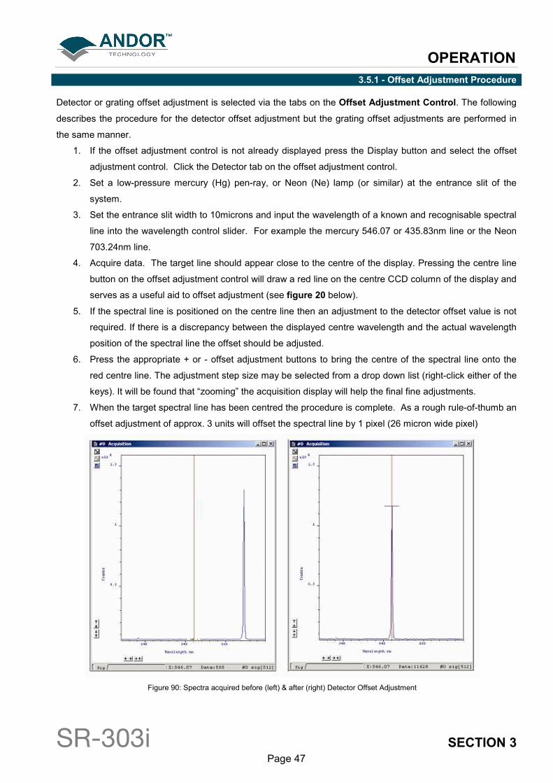
4. Acquire data. The target line should appear close to the centre of the display. Pressing the centre line
button on the offset adjustment control will draw a red line on the centre CCD column of the display and
serves as a useful aid to offset adjustment (see figure 20 below).
5. If the spectral line is positioned on the centre line then an adjustment to the detector offset value is not
required. If there is a discrepancy between the displayed centre wavelength and the actual wavelength
position of the spectral line the offset should be adjusted.
6. Press the appropriate + or - offset adjustment buttons to bring the centre of the spectral line onto the
red centre line. The adjustment step size may be selected from a drop down list (right-click either of the
keys). It will be found that “zooming” the acquisition display will help the final fine adjustments.
7. When the target spectral line has been centred the procedure is complete. As a rough rule-of-thumb an
offset adjustment of approx. 3 units will offset the spectral line by 1 pixel (26 micron wide pixel)
Figure 90: Spectra acquired before (left) & after (right) Detector Offset Adjustment

OPERATION
SR-303i SECTION 3 Page 48
3.6 - SLIT DRIVE CONTROL
The Slit Drive Control (figure 21) is used to control the Motorised Slit Assembly (see figure 32 on page 57).
The slits are used to control the amount of incident light that enters the spectrograph. The width can be varied
between 10µm and 2500µm (in steps of 2.5µm). The slit height may be altered by interchanging optional baffle
plates (attached to the slit assembly using 5x M2 cross-head screws). The system is supplied with a standard
4mm high x 6mm wide rectangular aperture baffle plate but there are also 8mm and 14mm high options
available. A 15mm diameter circular aperture is also available. If additional baffle options are required please
contact your nearest Andor representative.
In addition to controlling the level of illumination, the slit width also affects the resolution of the acquired data.
There is a trade-off between resolution and throughput. The narrower and shorter the slit the higher the
achievable resolution, but at the expense of throughput. As a general rule, it is best if the slit width is set as
narrow as possible while still achieving the required throughput. If the signal is too weak the slit width should
then be increased.
Figure 101: Slit Drive Control
The slit width can be input in a variety of ways:
1. By typing a new value into the slit width edit box and pressing Enter
2. By typing a new value into the slit width edit box and clicking the Set button
3. Clicking and dragging the edges of the slit in the graphic. Position the cursor over the grey “blade” area
of the slit graphic
4. When the cursor changes to a pointing hand, hold down the left mouse button and move the cursor to
open, or close, the slit edges. Regardless of which blade you drag, both blades move about the centre
of the slit
As you drag the blade the displayed slit width changes to reflect the selected width. The slit drive will drive to
the new width value when the mouse button is released.
The minimum and maximum operating values of the motorised slit are 10 and 2500 microns, respectively. If a
slit width input is outside of this range the system defaults to the nearest limit value.
The mechanism may be reset via the Reset button and selecting the Reset Slit option. On completion of a
‘reset’ the slit width will default to 10 microns.
OPERATION
SR-303i SECTION 3 Page 49
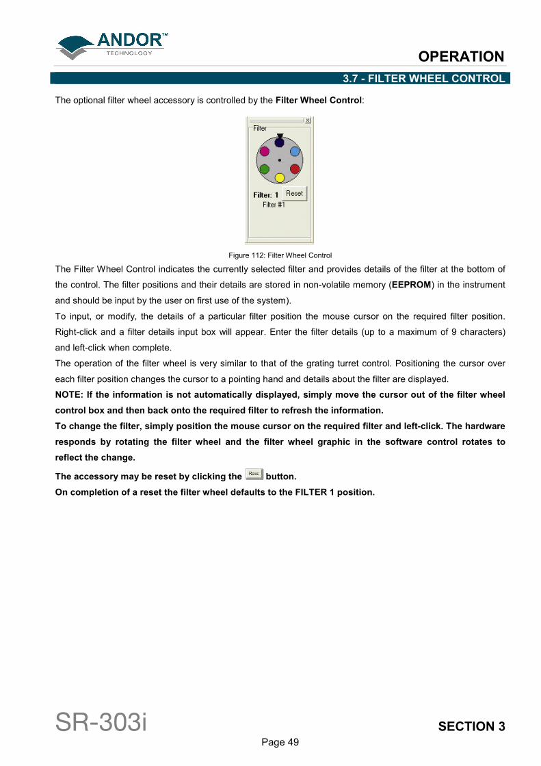
3.7 - FILTER WHEEL CONTROL
The optional filter wheel accessory is controlled by the Filter Wheel Control:
Figure 112: Filter Wheel Control
The Filter Wheel Control indicates the currently selected filter and provides details of the filter at the bottom of
the control. The filter positions and their details are stored in non-volatile memory (EEPROM) in the instrument
and should be input by the user on first use of the system).
To input, or modify, the details of a particular filter position the mouse cursor on the required filter position.
Right-click and a filter details input box will appear. Enter the filter details (up to a maximum of 9 characters)
and left-click when complete.
The operation of the filter wheel is very similar to that of the grating turret control. Positioning the cursor over
each filter position changes the cursor to a pointing hand and details about the filter are displayed.
NOTE: If the information is not automatically displayed, simply move the cursor out of the filter wheel
control box and then back onto the required filter to refresh the information.
To change the filter, simply position the mouse cursor on the required filter and left-click. The hardware
responds by rotating the filter wheel and the filter wheel graphic in the software control rotates to
reflect the change.
The accessory may be reset by clicking the button.
On completion of a reset the filter wheel defaults to the FILTER 1 position.
OPERATION
SR-303i SECTION 3 Page 50
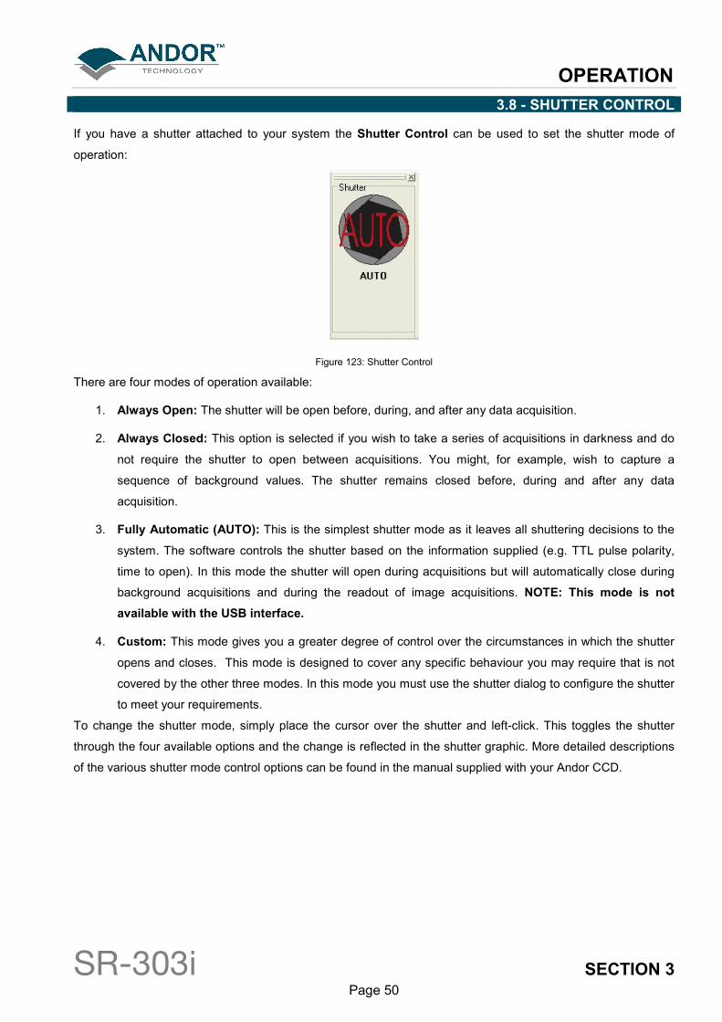
3.8 - SHUTTER CONTROL
If you have a shutter attached to your system the Shutter Control can be used to set the shutter mode of
operation:
Figure 123: Shutter Control
There are four modes of operation available:
1. Always Open: The shutter will be open before, during, and after any data acquisition.
2. Always Closed: This option is selected if you wish to take a series of acquisitions in darkness and do
not require the shutter to open between acquisitions. You might, for example, wish to capture a
sequence of background values. The shutter remains closed before, during and after any data
acquisition.
3. Fully Automatic (AUTO): This is the simplest shutter mode as it leaves all shuttering decisions to the
system. The software controls the shutter based on the information supplied (e.g. TTL pulse polarity,
time to open). In this mode the shutter will open during acquisitions but will automatically close during
background acquisitions and during the readout of image acquisitions. NOTE: This mode is not
available with the USB interface.
4. Custom: This mode gives you a greater degree of control over the circumstances in which the shutter
opens and closes. This mode is designed to cover any specific behaviour you may require that is not
covered by the other three modes. In this mode you must use the shutter dialog to configure the shutter
to meet your requirements.
To change the shutter mode, simply place the cursor over the shutter and left-click. This toggles the shutter
through the four available options and the change is reflected in the shutter graphic. More detailed descriptions
of the various shutter mode control options can be found in the manual supplied with your Andor CCD.
OPERATION
SR-303i SECTION 3 Page 51
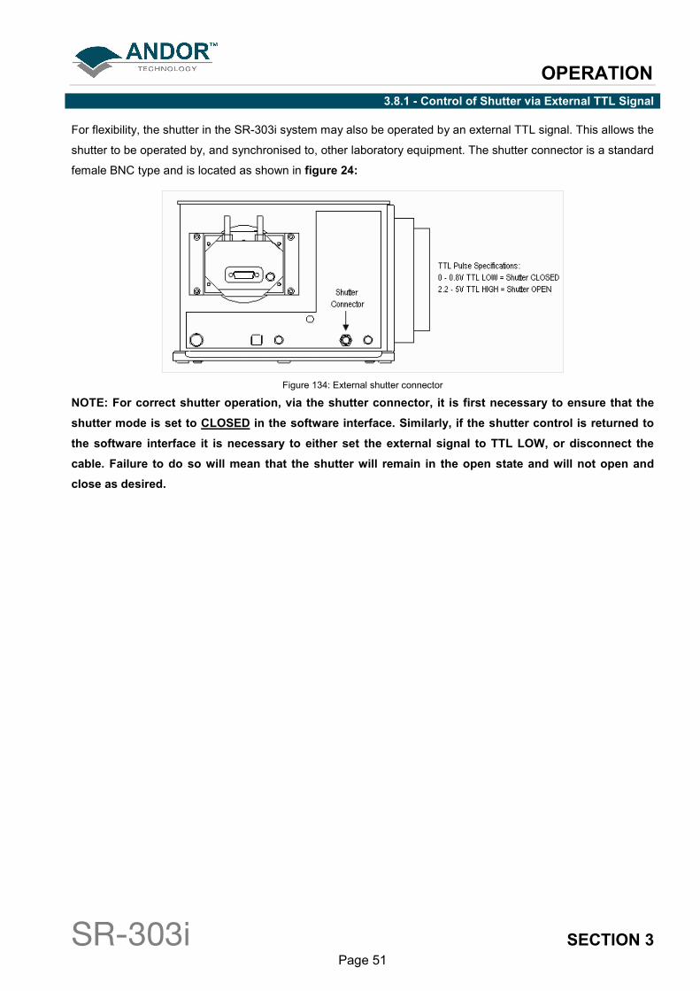
3.8.1 - Control of Shutter via External TTL Signal
For flexibility, the shutter in the SR-303i system may also be operated by an external TTL signal. This allows the
shutter to be operated by, and synchronised to, other laboratory equipment. The shutter connector is a standard
female BNC type and is located as shown in figure 24:
Figure 134: External shutter connector
NOTE: For correct shutter operation, via the shutter connector, it is first necessary to ensure that the
shutter mode is set to CLOSED in the software interface. Similarly, if the shutter control is returned to
the software interface it is necessary to either set the external signal to TTL LOW, or disconnect the
cable. Failure to do so will mean that the shutter will remain in the open state and will not open and
close as desired.

OPERATION
SR-303i SECTION 3 Page 52
3.8.2 - Fitting a Shutter to the Shamrock SR-303i
A shutter can be easily fitted or replaced by the user. Remove the 4off, M4 x 25mm cap-head screws attaching
the 25mm thick spacer block to the body of the spectrograph (figure 25). It is not necessary to unplug the slit
assembly ribbon cable.
1. Carefully allow the spacer block and slit assembly to fall forward.
Figure 25: Spacer Block Attachment Screws
2. Attach the shutter to the system using the three M2 x 6mm screws provided (do not over tighten) and
attach the 4-way electrical connector to the matching connector on the instrument.
3. Arrange the connector and wires into the recessed pocket taking care not to interfere with the shutter
actuator lever (figure 26):
Figure 146: Shutter (shown In-Situ)
4. Replace the spacer block and slit assembly
On re-start, the software will auto-detect that a shutter has been fitted, the shutter control will be displayed and
the shutter is now ready for use.
OPERATION
SR-303i SECTION 3 Page 53
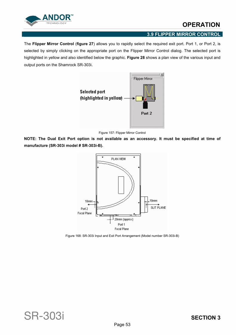
3.9 FLIPPER MIRROR CONTROL
The Flipper Mirror Control (figure 27) allows you to rapidly select the required exit port. Port 1, or Port 2, is
selected by simply clicking on the appropriate port on the Flipper Mirror Control dialog. The selected port is
highlighted in yellow and also identified below the graphic. Figure 28 shows a plan view of the various input and
output ports on the Shamrock SR-303i.
Figure 157: Flipper Mirror Control
NOTE: The Dual Exit Port option is not available as an accessory. It must be specified at time of
manufacture (SR-303i model # SR-303i-B).
Figure 168: SR-303i Input and Exit Port Arrangement (Model number SR-303i-B)
OPERATION
SR-303i SECTION 3 Page 54
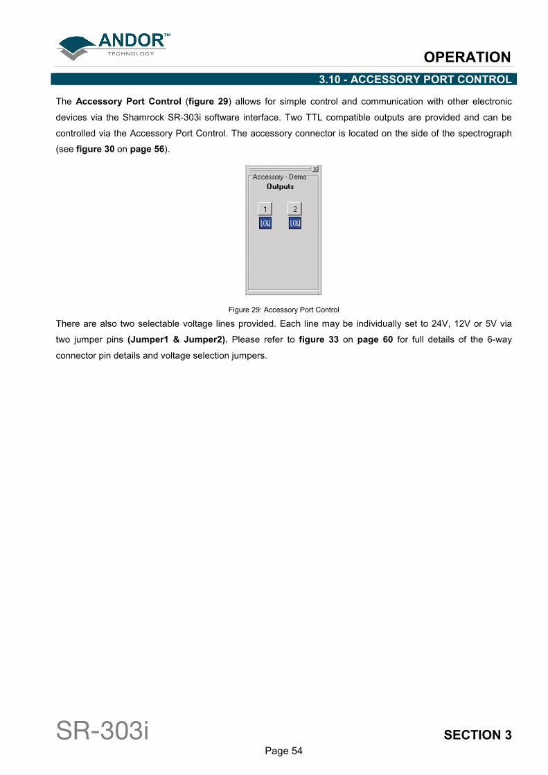
3.10 - ACCESSORY PORT CONTROL
The Accessory Port Control (figure 29) allows for simple control and communication with other electronic
devices via the Shamrock SR-303i software interface. Two TTL compatible outputs are provided and can be
controlled via the Accessory Port Control. The accessory connector is located on the side of the spectrograph
(see figure 30 on page 56).
Figure 29: Accessory Port Control
There are also two selectable voltage lines provided. Each line may be individually set to 24V, 12V or 5V via
two jumper pins (Jumper1 & Jumper2). Please refer to figure 33 on page 60 for full details of the 6-way
connector pin details and voltage selection jumpers.
APPENDIX
SR-303i SECTION 4 Page 55
APPENDIX
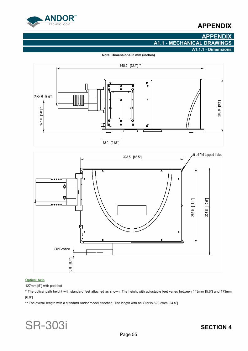
A1.1 - MECHANICAL DRAWINGS
A1.1.1 - Dimensions
Note: Dimensions in mm (inches)
Optical Axis
127mm [5”] with pad feet
* The optical path height with standard feet attached as shown. The height with adjustable feet varies between 143mm [5.6”] and 173mm
[6.8”]
** The overall length with a standard Andor model attached. The length with an iStar is 622.2mm [24.5”]
APPENDIX
SR-303i SECTION 4 Page 56
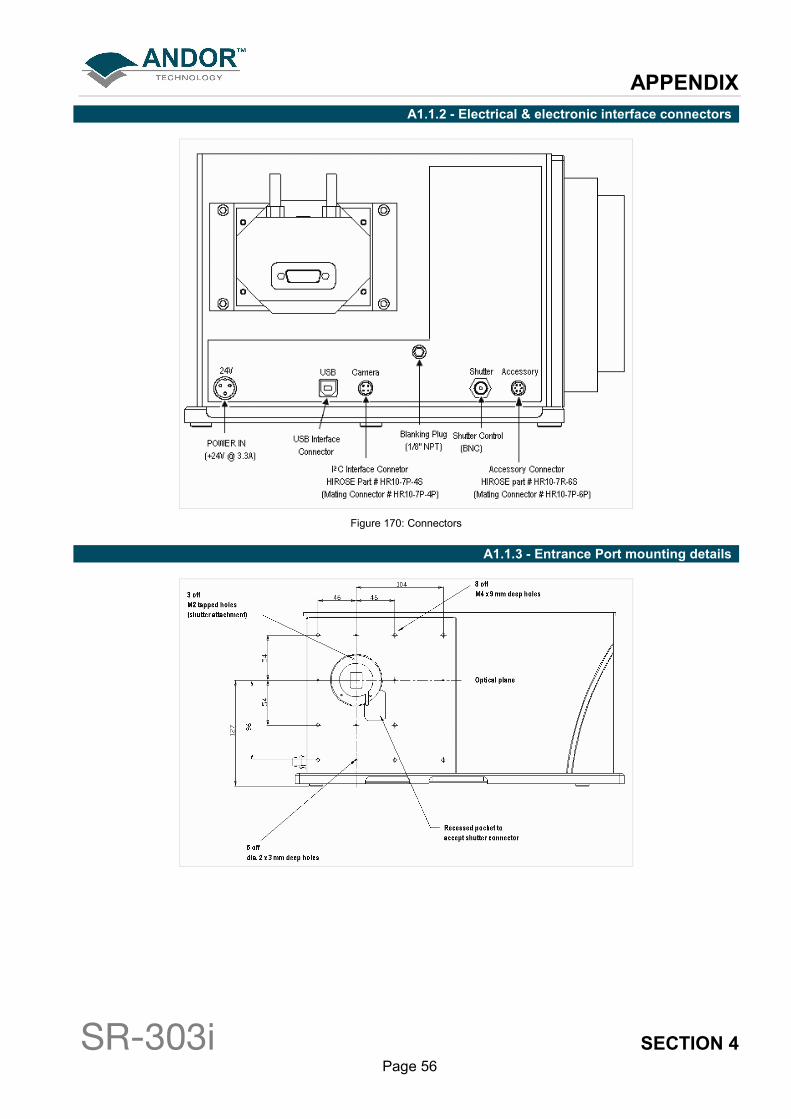
A1.1.2 - Electrical & electronic interface connectors
Figure 170: Connectors
A1.1.3 - Entrance Port mounting details
APPENDIX
SR-303i SECTION 4 Page 57
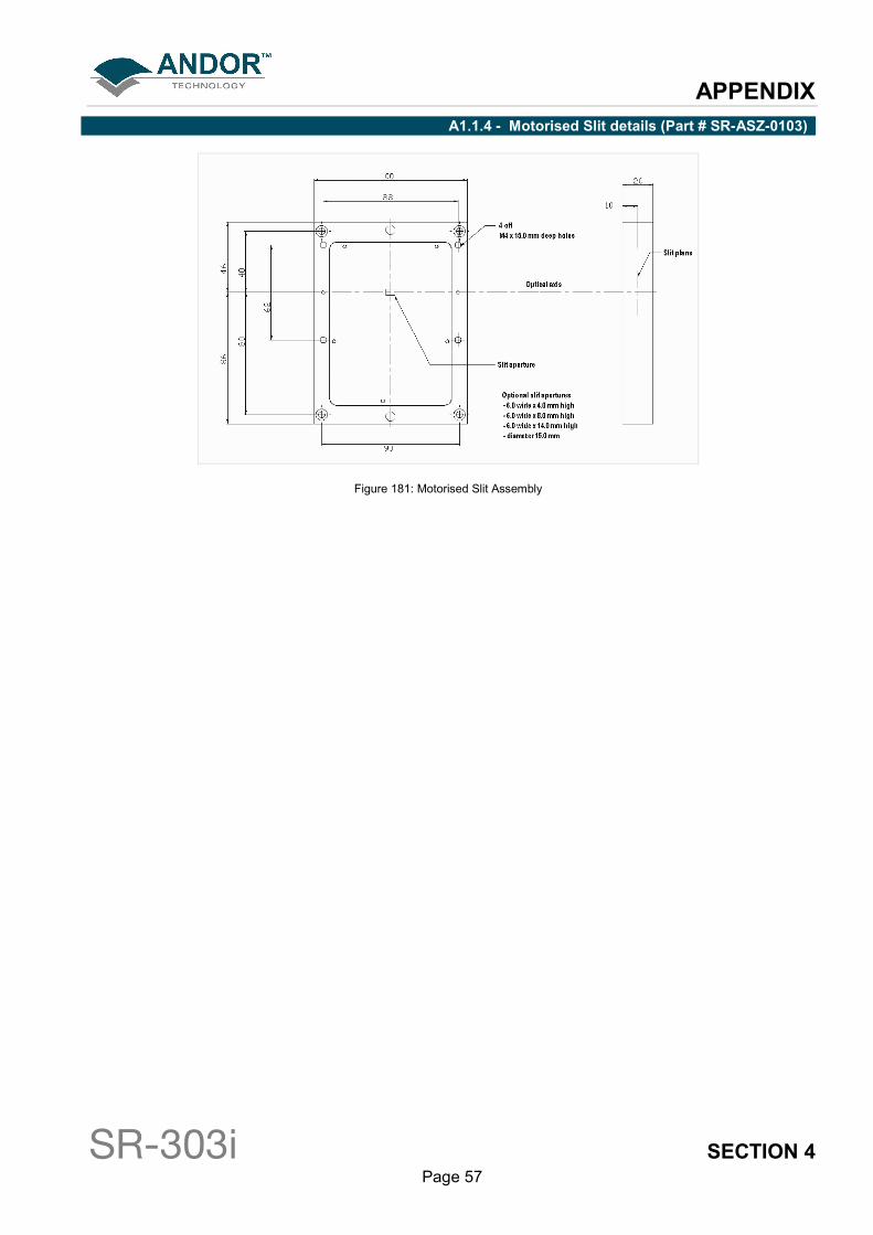
A1.1.4 - Motorised Slit details (Part # SR-ASZ-0103)
Figure 181: Motorised Slit Assembly
APPENDIX
SR-303i SECTION 4 Page 58
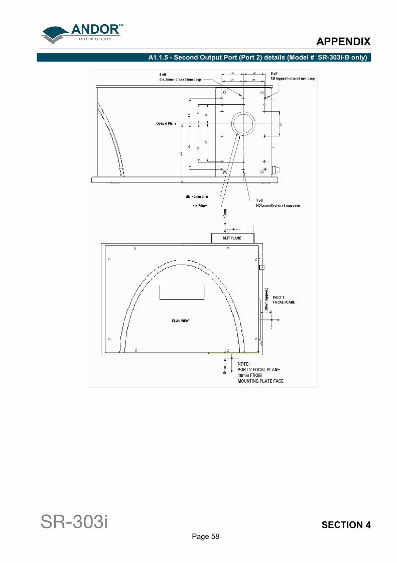
A1.1.5 - Second Output Port (Port 2) details (Model # SR-303i-B only)

APPENDIX
SR-303i SECTION 4 Page 59
A1.1.6- Alignment of optional Imaging Flange Accessory
Figure 192
Imaging property of SR-303i at the imaging plane

APPENDIX
SR-303i SECTION 4 Page 60
A1.1.7 - Accessory Connector Pin & Voltage Output Jumper Pin details
Figure 203: Accessory connector
IMPORTANT NOTE: The output voltages are mainly intended for attachment of Andor designed
accessories. Other devices should only be connected with caution.
Maximum current values are 24V@200mA, 12V@100mA and 5V@100mA.
Failure to observe these limits may damage the system.
APPENDIX
SR-303i SECTION 4 Page 61
A1.2- TERMS & CONDITIONS
1. In these Conditions:
‘BUYER’ means the person who accepts a quotation of the Seller for the sale of the Goods or whose order
for the Goods is accepted by the Seller.
‘GOODS’ means the goods (including any instalment of the goods or any parts for them) which the Seller is
to supply in accordance with these Conditions.
‘SELLER’ means Andor Technology plc.
‘CONDITIONS’ means the standard terms and conditions of sale set out in this document and (unless the
context otherwise requires) includes any special terms and conditions agreed in writing between the Buyer
and Seller.
‘CONTRACT’ means the contract for the purchase and sale of the Goods.
‘WRITING’ includes telex, cable, facsimile transmission and comparable means of communication.
2. Any reference in these Conditions to any provision of a statute shall be construed as a reference to that
provision as amended, re-enacted or extended at the relevant time.
3. The headings in these Conditions are for convenience only and shall not affect their interpretation.
APPENDIX
SR-303i SECTION 4 Page 62
A1.3 - WARRANTIES & LIABILITY
1. Subject to these Conditions set out below, the Seller warrants that the Goods will correspond with their
specification at the time of delivery and will be free from defects in material and workmanship for a period of 12
months from the date of delivery.
2. The above warranty is given by the Seller subject to the following conditions:
2.1 the Seller shall be under no liability in respect of any defect in the Goods arising from any drawing, design
or specifications supplied by the Buyer;
2.2 the Seller shall be under no liability in respect of any defect arising from fair wear and tear, wilful damage,
negligence, abnormal working conditions, failure to follow the Seller’s instructions (whether oral or in writing),
misuse or alteration or repair of the Goods without the Seller’s. approval;
2.3 the Seller shall be under no liability under the above warranty (or other warranty, condition or guarantee) if
the total price for the Goods has not been paid by the due date for payment;
2.4 the above warranty does not extend to parts, material or equipment not manufactured by the Seller, in
respect of which the Buyer shall only be entitled to the benefit of any such warranty or guarantee as is given by
the manufacturer to the Seller.
3. Subject as expressly provided in these conditions, and except where the Goods are sold to a person dealing
as a consumer (within the meaning of the Unfair Contract Terms Act 1977), all warranties, conditions or other
terms implied by statute or common law are excluded to the fullest extent permitted by law.
4. Any claim by the Buyer which is based on any defect in the quality or condition of the Goods or their failure
to correspond with specification shall (whether or not delivery is refused by the Buyer) be notified in Writing to
the Seller within 7 days from the date of delivery or (where the defect or failure was not apparent on reasonable
inspection) discovery of the defect or failure. If delivery is not refused, and the Buyer does not notify the Seller
accordingly, the Buyer shall not be entitled to reject the Goods and the Seller shall have no liability for such
defect or failure, and the Buyer shall be bound to pay the price as if the Goods had been delivered in
accordance with the Contract. In no event shall the Buyer be entitled to reject the Goods on the basis of any
defect or failure which is so slight that it would be unreasonable for him to reject them.
5. Where any valid claim in respect of the Goods which is based on any defect in the quality or condition of the
Goods or their failure to meet specification is notified to the Seller in accordance with these Conditions, the
Seller shall be entitled to replace the Goods (or the part in question) free of charge or, at the Seller’s sole
discretion, refund to the Buyer the price of the Goods (or a proportionate part of the price), but the Seller shall
have no further liability to the Buyer.
APPENDIX
SR-303i SECTION 4 Page 63
6. Except in respect of death or personal injury caused by the Seller’s negligence, the Seller shall not be liable
to the Buyer by reason of any representation (unless fraudulent), or any implied warranty, condition or other
term, or any duty at common law, or under the express terms of the Contract, for any indirect, special or
consequential loss or damage (whether for loss of profit or otherwise), costs, expenses or other claims for
compensation whatsoever (whether caused by the negligence of the Seller, its employees or against otherwise)
which arise out of or in connection with the supply of the Goods, or their use or resale by the Buyer and the
entire liability of the Seller under or in connection with the Contract shall not exceed the price of the goods,
except as expressly provided in these Conditions.
7. The Seller shall not be liable to the Buyer or be deemed to be in breach of the Contract by reason of any
delay in performing, or any failure to perform, any of the Seller’s obligations in relation to the goods, if the delay
or failure was due to any cause beyond the Seller’s reasonable control. Without prejudice to the generality of
the foregoing, the following shall be regarded as causes beyond the Seller’s reasonable control:
7.1 Act of God, explosion, flood, tempest, fire or accident;
7.2 war or threat of war, sabotage, insurrection, civil disturbance or requisition;
7.3 acts, restrictions, regulations, bye-laws, prohibitions or measures of any kind on the part of any
governmental, parliamentary or local authority;
7.4 import or export regulations or embargoes;
7.5 strikes, lock-outs or other industrial actions or trade disputes (whether involving employees of the Seller or
of third party);
7.6 difficulties in obtaining raw materials, labour, fuel, parts or machinery;
7.7 power failure or breakdown in machinery.