Some Basics To Know When Specifying and Using On … SPE 2011 Presentation - Leak... · Some Basics...
22
© 2011 Air Logic Power Systems, LLC Leak Testing Equipment “Leak Testing 101” Some Basics To Know When Specifying and Using On-Line Leak Testing Equipment Scott Heins ALPS Sales Manager SPE Blow Molding Conference Oct 13, 2011
Transcript of Some Basics To Know When Specifying and Using On … SPE 2011 Presentation - Leak... · Some Basics...

© 2011 Air Logic Power Systems, LLC
Leak Testing Equipment
“Leak Testing 101”
Some Basics To Know When Specifying and Using
On-Line Leak Testing Equipment
Scott Heins ALPS Sales Manager
SPE Blow Molding Conference Oct 13, 2011

© 2011 Air Logic Power Systems, LLC
Leak Testing Equipment
MACHINE TYPES
PLANT CONDITIONS
TEST METHOD
WHY LEAK TEST?
© 2011 Air Logic Power Systems, LLC
Leak Testing Equipment
Back to Outline
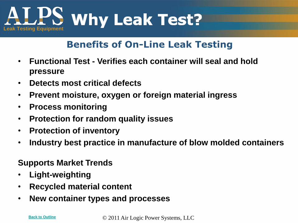
• Functional Test - Verifies each container will seal and hold
pressure
• Detects most critical defects
• Prevent moisture, oxygen or foreign material ingress
• Process monitoring
• Protection for random quality issues
• Protection of inventory
• Industry best practice in manufacture of blow molded containers
Supports Market Trends
• Light-weighting
• Recycled material content
• New container types and processes
Benefits of On-Line Leak Testing

© 2011 Air Logic Power Systems, LLC
Leak Testing Equipment
Pressure Decay Theory of Operation
How It Works:
• “Pressure Decay” test method is dominant for blow molded containers
• A test probe is extended to form a leak tight seal on each container
• The container is pressurized
• Detect leaks as a larger pressure drop compared to good containers
Back to Outline Back to Test Method

© 2011 Air Logic Power Systems, LLC
Leak Testing Equipment
Typically 3-Step Test
• Fill: Container filled to target pressure
• T1: Measure an initial pressure change
„Stabilization‟ time (adiabatic cooling)
• T2: Measure a final pressure change
Pressure Decay Test Method
Back to Outline Back to Test Method
Detection Result:
• ‘Gross’ reject
• ‘Medium’ leak
• ‘Small’ leak

© 2011 Air Logic Power Systems, LLC
Leak Testing Equipment
Back to Outline Back to Test Method
Realities of Blow Molded Container Leak Testing:
• Larger Volume Parts will require more time to detect the same hole size
• Takes longer to detect change in pressure
• Detecting loss of a drop of water in a thimble vs. bathtub analogy
• Longer Test Times are required to detect smaller leaks in a given container
• Pressure will tend to level out in good containers
• Pressure will continue to drop in leaking containers
Pressure Decay Test Method

© 2011 Air Logic Power Systems, LLC
Leak Testing Equipment
• P = Pressure (atm)
• V = Volume (liters)
• n = number of moles (mass/molecular mass)
• n stays constant for non leaking parts
• n decreases for leaking parts
• R = Universal gas constant (0.0821 L-atm/mol-K)
• T = Temperature (Kelvin)
Back to Outline Back to Test Method
Ideal Gas Law: PV = nRT or P = nRT/V
Some Effects of the Laws of Physics:
• Pressure Loss will typically occur in Good parts due to adiabatic cooling and
(Temperature drop) and container stretch (Volume increase)
• Temperature variations in the product will cause Pressure variations. The
main effect of hot plastic is creation of a pressure rise inside the container
when it is closed for the leak test.
• Bottle Compression (Volume drop) during the test will cause a pressure rise

© 2011 Air Logic Power Systems, LLC
Leak Testing Equipment
Test Verification Methods
Self Test Pushbutton
Back to Outline Back to Test Method
• Metal Orifices with a known diameter are used to simulate leaks
• This is more precise and repeatable than poking a hole in a bottle
• These can be installed directly into Test Bottles (image at left) and run through the
leak tester to verify performance
• The Metal Orifice can be installed onto a Test Leak Valve on the machine
• A Self Test function can be performed by pressing a button that activates the Test
Leak Valve prior to the next leak test of a bottle
Test Leak Valve

© 2011 Air Logic Power Systems, LLC
Leak Testing Equipment
Typical Parameters for Blow Molded Containers
Back to Outline Back to Test Method
Bottle Sizes
• From 3cc vials/droppers up to 300 oz Detergent / 5 Gallon Edible Oil for
common automated machines
Metal Paper Clip
0.030”
(0.75mm)
Avg. human hair
0.003”
(0.075mm )
Hole Sizes
• From 0.004” to 0.020” / 0.030”
Speeds
• Up to 1000 BPM applications in the market today
Test Times
• From tens of milliseconds on very small parts to several seconds

© 2011 Air Logic Power Systems, LLC
Leak Testing Equipment
Lab vs. Production Line Results
Back to Outline
A leak test will be more accurate, consistent and repeatable
under lab conditions vs. on the production line
Reasons for Test Variations on Production Lines
• Greater population of containers
• Container dimensional variations (volume, stretch behavior)
e.g. motor oil container „paneling‟
• Changes in elasticity or stretch
e.g. wall thickness variations
• Container temperature variations
e.g. mixture of hot and cured bottles
• Handling and presentation to the leak tester

© 2011 Air Logic Power Systems, LLC
Leak Testing Equipment
Recommendations on the Production Line
Back to Outline Back to Plant Conditions
• Do not position the leak tester next to a heat source (e.g. flamer or blow
molder) if possible
• Present the containers to the tester in as close to „cured‟ state as practical
• Set up the leak tester to maximize test time
• Do not expect the same hole size for every container if the bottle volumes
and test times vary
• Pay attention to container handling through the leak tester
• Minimize sealing force as much as possible
• Considering the range of container variability when choosing reject limits
i.e. don‟t set too tight based on feedback from a few bottles
• Have a plan in place to „challenge‟ the leak tester – Determine method
(e.g. Self Test) and how often
• Watch your seals carefully

© 2011 Air Logic Power Systems, LLC
Leak Testing Equipment
Importance of Seals
Back to Outline
The seal is the conduit for the leak test – it must be
reliable and leak tight for good results
• The leak test provides a functional test of the Seal Surface integrity, which
can be tuned to the desired sensitivity
• Select an appropriate seal durometer (hardness) for the application
• Select an appropriate sealing force to reduce false rejects and detect the
desired level of seal defects
• Probes and seals can be customized to focus on a specific area of the
seal surface if desired
• If you are focusing on a specific Seal Surface test for a particular
container, create „challenge samples‟ for the leak tester

© 2011 Air Logic Power Systems, LLC
Leak Testing Equipment
Machine Type #1: Bottle Stop, Conveyor Method
Back to Outline Back to Machine Factors
• Separate, dedicated leak tester conveyor
• Stops bottles for the leak test by stopping the conveyor
• Vacuum conveyor assists bottle stability and handling speed
• Requires transfer of bottles to/from the leak tester conveyor
Requires Conveyor Transfers
© 2011 Air Logic Power Systems, LLC
Leak Testing Equipment
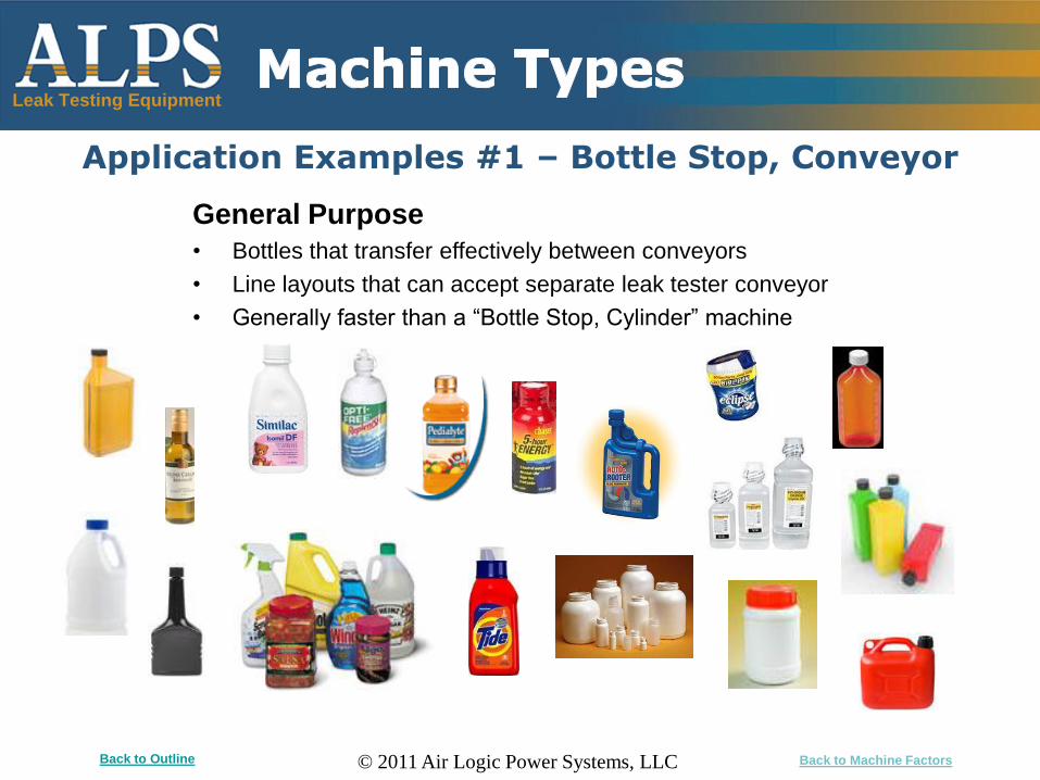
Application Examples #1 – Bottle Stop, Conveyor
Back to Outline Back to Machine Factors
General Purpose
• Bottles that transfer effectively between conveyors
• Line layouts that can accept separate leak tester conveyor
• Generally faster than a “Bottle Stop, Cylinder” machine

© 2011 Air Logic Power Systems, LLC
Leak Testing Equipment
Machine Type #2: Bottle Stop, Cylinder Method
Back to Outline Back to Machine Factors
• Stops bottles for the leak test, using a cylinder
• Requires Gate cylinder to regulate containers; and downstream Reject
• Conveyor is typically running continuously underneath
• Bottles must be stable enough to be stopped on-the-fly

© 2011 Air Logic Power Systems, LLC
Leak Testing Equipment
Application Examples #2 – Bottle Stop, Cylinder
Back to Outline Back to Machine Factors
Angle neck bottles
• Bottles are stopped/captured
• Requires test probe mount with adjustable angle
General purpose
• Cases in which a conveyor transfer of bottles is not desired
• Bottles must be stable enough to be stopped „on the fly‟

© 2011 Air Logic Power Systems, LLC
Leak Testing Equipment
Machine Type #3: Linear Continuous Motion
Back to Outline Back to Machine Factors
Timing Screw Handling
• Mounts over existing conveyor
• Uses timing screw to separate bottles for the
leak test
• Test head(s) follow the bottle during travel in
the timing screw
Timing Screw
Slide & Test Probe Assembly Encoder Wheel
Conveyor Following
• Mounts over existing conveyor
• Follows and tests bottles „on the fly‟
• Probe carriage driven by linear slide
• Slide speed is matched by monitoring
conveyor with encoder wheel

© 2011 Air Logic Power Systems, LLC
Leak Testing Equipment
Application Examples #3 – Linear Continuous Motion
Back to Outline Back to Machine Factors
Very small pharma bottles • Tiny footprints
• Avoid conveyor transfers
• Avoid touching of bottles (Conveyor Following version)
Teardrop shapes • Small, non-straight sides; often „sticky‟ polypropylene
• Avoid conveyor transfers
• Avoid touching of bottles (Conveyor Following version)
‘Tri’ shaped drug bottles • Avoid conveyor transfers, bottles „wedging‟
• Avoid touching of bottles (Conveyor Following version)
Personal care bottles • Reverse tapers and sharp corners
• Avoid touching of bottles (Conveyor Following version)

© 2011 Air Logic Power Systems, LLC
Leak Testing Equipment
Machine Type #4: Rotary Continuous Motion
Back to Outline Back to Machine Factors
• Timing screw separates bottles to the machine „pitch‟
• Bottles travel through the machine in a continuous motion
• Dedicated change parts for each container
• Longest test time approach by creating bottle path on turntable
• Most sensitive leak test for a given speed

© 2011 Air Logic Power Systems, LLC
Leak Testing Equipment
Application Examples #4 – Rotary Continuous Motion
Back to Outline Back to Machine Factors
Hot Fill & Custom PET
Long Stroke Shuttle Blow Molded Containers
Wheel Blow Molded Containers

© 2011 Air Logic Power Systems, LLC
Leak Testing Equipment
Comparison of Machine Types
Back to Outline Back to Machine Factors
#1 Bottle Stop, Conveyor Method good for general purpose
• Conveyor type and speed is optimized for the leak test
• Setup is simplified = one photoeye and simple conveyor stop handling
#2 Bottle Stop, Cylinder Method is lowest cost for conveyor mount
• Bottles must be stable enough to be stopped on the fly
• Speeds are not as high as other unit styles
• More setup items = Gate, Stop and Reject eyes and cylinders
#3 Linear Continuous Motion for harder-to-handle containers
• Severe ovals (shinglers), reverse tapers, high height-to-base ratios (3:1
to 4:1+), very small bottles
• Setup is simplified = one photoeye
• Mounts and tests over existing conveyor, to avoid bottle transfers
#4 Rotary Continuous Motion for high speeds and/or micro leak testing

© 2011 Air Logic Power Systems, LLC
Leak Testing Equipment
1745 S. 38th Street, Suite 100 Milwaukee, WI 53215-2017
Phone: 414-671-3332 ; Fax: 414-671-6645 24-Hour Service Hotline: 800-325-8717
Email: [email protected] Web: www.alpsleak.com
Back to Outline
Thank You