SMALL PROJECT EROSION & SEDIMENT … project . erosion & sediment control plan guide . snyder county...
30
SMALL PROJECT EROSION & SEDIMENT CONTROL PLAN GUIDE SNYDER COUNTY CONSERVATION DISTRICT 10541 Rt. 522 Middleburg, PA 17842 Phone: 570 837-3000 Ext. 113 or 110 Fax: 570 837-7300
Transcript of SMALL PROJECT EROSION & SEDIMENT … project . erosion & sediment control plan guide . snyder county...

SMALL PROJECT
EROSION & SEDIMENT CONTROL PLAN GUIDE
SNYDER COUNTY CONSERVATION DISTRICT 10541 Rt. 522
Middleburg, PA 17842 Phone: 570 837-3000 Ext. 113 or 110
Fax: 570 837-7300

1 Revised 12/1/10
Table of Contents
INTRODUCTION, PURPOSE, & CONSIDERATIONS.…………………………………….…..PAGE 2 INCLUSIONS, SUGGESTIONS, & RECOMMENDATIONS…………………………………...PAGE 3 UP-SLOPE DRAINAGE & DETAIL SHEETS REFERENCE…………….…………………….PAGE 4 SMALL PROJECT E&S CONTROL PLAN APPLICATION………...………………………....PAGES 5-7 BEST MANAGEMENT PRACTICES (BMPS) …………………………………………………...PAGES 8-24 APPENDICES A, B, C, & D…………………………………………………………………………PAGES 25-28 GLOSSARY………………………………………………………………………………………….PAGE 29

2 Revised 12/1/10
INTRODUCTION Noticing low levels of sediment in the streams and rivers of Pennsylvania during times of high flows and velocities is a natural event known as sedimentation. However, accelerated erosion and sediment pollution resulting from human activities, smothers and destroys aquatic life. It also causes losses of valuable topsoil and impairs water quality. Sediment pollution is the single largest pollutant, by volume, to the streams and waterways of the Commonwealth. Sediment pollution can simply be defined as any man-made earth disturbance that leads to increases in sediment (clays, silts, sands, and other “mud”) levels in streams, wetlands, and watercourses. In an attempt to control accelerated erosion and sediment pollution, the Pennsylvania Department of Environmental Protection (PA DEP) adopted Chapter 102, Erosion and Sediment Control Rules and Regulations, in accordance with the PA Clean Streams Law. Under current Chapter 102 regulations, anyone involved with an earth disturbance activity (i.e. digging, grubbing, grading, or in any way disturbing the topsoil) exceeding 5,000 square feet or more is required to develop, implement, and maintain an Erosion and Sediment (E&S) Control Plan. This Plan must be submitted to the Snyder County Conservation District if required by the municipality in which the earth disturbance activity is to be conducted or if requested by the District. REMEMBER: Both Chapter 102 and the PA Clean Streams Law regulations specify that there may be an equal responsibility between both the landowner and contractor if sediment-laden waters are discharged from the construction site.
PURPOSE OF THIS GUIDE This document was designed to assist landowners in developing and implementing an E&S Control Plan for small-scale, low-hazard projects. Use of this guide may be limited to:
• Projects where earth disturbance activities are greater than 5,000 square feet, but less than 43,560 square feet (i.e. one acre).
• Projects where the existing slopes on the site are either A, B, or C, and do not exceed 15% (Note: the slope criterion is based on the soil symbols located within the Soil Survey of Snyder County, PA).
• Projects with no associated impact to wetlands, streams, or major waterways (i.e. a Chapter 105 General Permit – GP is not applicable for this type of Plan).
CONSIDERATIONS IN PLAN DEVELOPMENT
Practice Proper Site Grading-Hold Grading to a Minimum The risk of severe erosion increases in a direct proportion to the amount of an individual site’s earth disturbance. Excessive cutting and filling may alter the ground water system, open seeps, create sinkholes, and expose unstable soils. Improperly compacted fills may also be extremely erosive. Cutting, filling, and road grades over 10% require more intensive stabilization and often result in more long-term stabilization problems. All of the topsoil from areas where cuts and fills have been made should be stockpiled and redistributed uniformly during the final grading stage of the project. This is the key to properly re-vegetating the site. Save Existing Vegetation, Especially Trees A vegetative cover is the best and most economical protection against soil erosion. Vegetation and trees should be protected during construction to prevent damage from equipment (i.e. secure an area around the tree root systems so that they are not destroyed). Minimize the Area and Time of Exposure Any disturbed area should be stabilized as soon as the earth disturbance activity is completed or the earth moving activities have temporarily ceased (i.e. usually this means the area should be seeded and mulched). Minimize the amount of disturbed ground at any given time. Sequence the construction such that only the areas to be immediately worked on are disturbed. Permanent site stabilization should not be postponed until the entire project is completed (ex. a stone base should be applied immediately after the driveway has been excavated).

3 Revised 12/1/10
Protect Any Watercourses or Wetlands Install temporary Best Management Practices (BMPs), such as straw bales, silt fence, or silt socks in order to prevent sediment pollution to Commonwealth waters. Remember the basic idea: “We All Live Downstream”. Maintenance Plan to inspect and repair all E&S Control BMPs after every significant rain event, and at the end of each week, at a minimum. Remember that E&S Control BMPs are not totally maintenance free (i.e. rock construction entrances become encrusted with extraneous soils, silt fences become overwhelmed with sediment, and re-vegetated areas sometimes wash out prior to permanent vegetation becoming established).
WHAT SHOULD BE INCLUDED IN AN EROSION AND SEDIMENT CONTROL PLAN?
1. Complete Plot Plan drawing (not to scale – refer to pg. 7). 2. Existing topography of the site (slope directions and estimated grades). 3. Location of any water bodies (streams, ditches, springs, etc.). 4. Brief description of the proposed project. 5. Types of E&S Control BMPs to be used and their locations on the site.
SOME SUGGESTIONS FOR A CONSTRUCTION SEQUENCE
1. Cut and install a stone-based driveway or access area for equipment such as a rock construction entrance. 2. Install all temporary E&S Control BMPs such as straw bales, silt fence, etc. 3. Strip topsoil from areas where work will begin, stockpile for final stabilization of site. 4. Construct buildings(s) and begin rough grading activities. 5. Finish grading and permanently stabilize entire site with seed, mulch, stone, etc. 6. Remove all temporary BMPs after site is completely stabilized (i.e. a minimum of at least 70% uniform
perennial vegetative cover with a density able to resist accelerated erosion).
SEEDING AND MULCHING RECOMMENDATIONS Temporary Seeding Recommendations/Mixtures If temporary seeding is necessary, follow the chart below. Then, when final stabilization is to be completed, apply the remainder of the recommendations below for lime and fertilizer prior to final seeding and mulching. Annual Ryegrass is a quick germinating species of grass that can be seeded at almost any time. If you plan to leave your project or part of your project area inactive before final stabilization/permanent cover is achieved, a temporary seeding should be applied immediately. General recommendations are as follows: Lime 1 ton per acre 50 lbs. per 1000 square feet Fertilizer 150 lbs. per acre 5 lbs. per 1000 square feet Annual Ryegrass 40 lbs. per acre 1 lbs. per 1000 square feet Permanent Seeding Mixtures Establishing a permanent vegetative cover is the final step to effective erosion and sediment pollution control. It is recommended that the Penn State Agronomy Guide be consulted (available from PSU Cooperative Extension or the Snyder County Conservation District). All mixtures below are for 100% Pure Live Seed (PLS). Depending on your percent of PLS, you may have to adjust recommendations accordingly. General recommendations are as follows:
Lawn and Mowed Areas A. Kentucky Bluegrass Redtop Perennial Ryegrass
30 lbs. per acre 3 lbs. per acre 20 lbs. per acre
12 oz. per 1000 square feet 2 oz. per 1000 square feet 8 oz. per 1000 square feet
B. Pennlawn-Fine Fescue Redtop Perennial Ryegrass
40 lbs. per acre 3 lbs. per acre 20 lbs. per acre
16 oz. per 1000 square feet 2 oz. per 1000 square feet 8 oz. per 1000 square feet
4 Revised 12/1/10
Slopes and Un-Mowed Areas Crown Vetch Perennial Ryegrass
25 lbs. per acre 25 lbs. per acre
10 oz. per 1000 square feet 10 oz. per 1000 square feet
Note: Crown Vetch is a legume and requires an inoculant. Contact your seed supplier for more specific information. Although providing a thick ground cover, crown vetch is also an extremely aggressive invasive species, offering little wildlife benefit. Use with caution. Timing of Permanent Seeding For best results, grass and legume seeding should be completed in the spring; however, with proper establishment techniques, disturbed sites can be seeded almost anytime from spring to fall. General rules are as follows: legume seeding needs 10-12 growing weeks prior to hard frost and grasses generally require 4-6 weeks of growth prior to hard frost. Lime Adding agricultural grade limestone to a site is often the key to establishing vegetation. Soil tests from a reputable source such as the U.S. Farm Service Agency are recommended. But in the case where test results are not available, use the guide below. Fertilizer – Commercial Type 10-20-20 The need for fertilizer cannot be underestimated. Soil tests are again recommended, but the guide below can be used in their absence. Mulch (Straw, Hay, or Bark) All areas that are subject to stabilization, whether it be with the temporary or permanent seeding specifications, should be mulched. Mulch is a loose layer of straw, hay, or bark that is at least 1” in depth. Mulch reduces the potential for erosion of soils and aids in seedling germination. Reference the specific recommendations by using the guide below. Lime 4 tons per acre 190 lbs. per 1000 square feet Fertilizer 930 lbs. per acre 25 lbs. per 1000 square feet Mulch (Straw, Hay, or Bark) 3 tons per acre 140 lbs. per 1000 square feet
UP - SLOPE DRAINAGE It is important to consider the aspect of stormwater and off-site runoff as it could affect your site. Areas up-slope of your construction site may allow large amounts of water to run onto your site. This water should be diverted around or through your site in such a way that this water does not pick up any additional sediment from your construction activities. The basic concept is to keep the clean water clean, and treat the dirty (sediment-laden) water before it leaves your site. Downspouts, swale outlets, parking lots, and other items that collect and concentrate water have the potential to cause soil erosion both on your site and on adjoining properties. Take care to plan for stormwater related issues during construction.
E&S CONTROL PLAN DETAIL SHEETS (REFER TO PGS. 8 -24) This section is primarily devoted to providing a detailed installation instruction for E&S Control BMPs, and general rules of thumb as to when each BMP should be used. This guide is designed so landowners can plan for and install E&S Control BMPs to minimize accelerated erosion, and meet both the regulations set forth in Chapter 102 and the PA Clean Streams Law. The details that follow were excerpted from PA DEP’s Erosion and Sediment Pollution Control Program Manual, May 2000. These are not the only BMPs that can be used, but are ones that have been previously reviewed, approved, and recommended. This guide is not intended to be a substitute for E&S Control Plans developed for complex, multiple acre, or high-hazard sites. Professional engineering consulting firms should be considered for sites requiring permanent E&S Control BMPs or sites where the potential for sediment pollution to Commonwealth waters are high. The Snyder County Conservation District will gladly assist you in completing this Small Project E&S Control Plan guide and also aide you in determining if a more “detailed” E&S Control Plan will be necessary.

5 Revised 12/1/10
EROSION AND SEDIMENT CONTROL PLAN INFORMATION SHEET Property Owner: ________________________________________________ Date: ______________
Address: __________________________________ City: _________________ State & Zip:__________
Phone Number: ________________ Municipality: ____________________________
Contact Person (if other than owner):_____________________________________________________
Contact Person’s Address:______________________________________________________________
Contact Person’s Phone Number: ___________________________________________________________
Location of Project: __________________________________________________________________
Name of Nearest Receiving Stream, Wetland, or Waterbody: _________________________________
Estimated Dates for Start-Up and Completion: Start: ____________________ End: ________________
Project Acres (entire site):_________________________ Disturbed Area: ______________________
Present Site Conditions (i.e. type of land use):______________________________________________
___________________________________________________________________________________
Narrative (give specific description of the proposed work):
___________________________________________________________________________________
___________________________________________________________________________________
___________________________________________________________________________________
___________________________________________________________________________________
___________________________________________________________________________________
___________________________________________________________________________________
___________________________________________________________________________________
___________________________________________________________________________________
___________________________________________________________________________________
Sequence of Construction (specifically, what will be done first, second, third, etc.):
___________________________________________________________________________________
___________________________________________________________________________________
___________________________________________________________________________________
___________________________________________________________________________________
___________________________________________________________________________________
___________________________________________________________________________________
___________________________________________________________________________________
___________________________________________________________________________________

6 Revised 12/1/10
Best Management Practices (BMPs): Check if applicable: ___ rock construction entrance ___ rock filters ___ straw bale barrier ___ waterbar ___ filter fabric (silt) fence ___ sediment filter log (straw waddle) ___ silt fence reinforced by staked strawbale ___ temporary swale w/rip-rap apron ___ compost filter berm ___ permanent diversion channel w/rip-rap apron ___ compost filter sock ___ temporary seeding/mulching ___ wood chip filter berm ___ permanent seeding/mulching List other alternative BMPs: ____________________________________________________________________
Describe any temporary E&S Control BMPs you will be using on your site (such as silt fence, rock filters,
temporary seeding, etc.).
___________________________________________________________________________________
___________________________________________________________________________________
___________________________________________________________________________________
___________________________________________________________________________________
___________________________________________________________________________________
___________________________________________________________________________________
___________________________________________________________________________________
Note: A copy of this Small Project Plan should be kept on site during the construction activity and your contractor should have a copy of this Small Project Plan available at all times. The
Snyder County Conservation District will also keep a copy of your Small Project Plan on record in our office.
Post Construction Stormwater Management (PCSM) Plans: Do They Apply To A Small Project?
According to the most recent Chapter 102 regulation changes which were (proposals set forth by PA DEP on
August 21, 2010) enacted on November 19, 2010, the following conditions apply to a Small Project:
• The revision provides that for minor projects when there is little or no change in the runoff characteristics
from the site, the PCSM Plan can be brief, can be only a sentence or two, and still meet requirements of
Subsection 102.8a.
Essentially, the District’s interpretation of this change is that it will be left up to the individual municipality to
decide how they will apply this PCSM regulation (per the Small Project E&S Control Plan). The District
(in making this determination) is not attempting to skirt the issue of the PCSM Plan regulation, but rather,
requesting municipal guidance since it will be determined by the municipality how to provide for these changes in
their individual Subdivision and Land Development Ordinance codes which may also involve the inspection of the
PCSM Plan BMP installation.
Please refer to Appendices A and B (on pgs. 25 and 26) for suggested PCSM Plan BMPs.
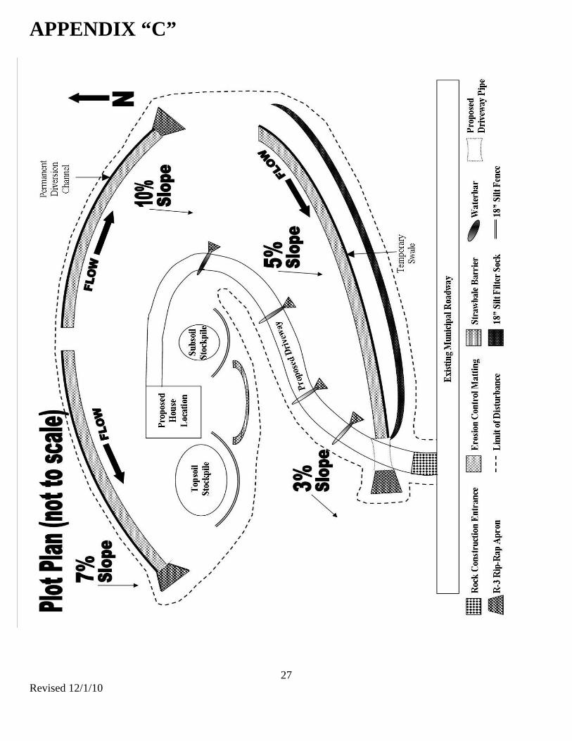
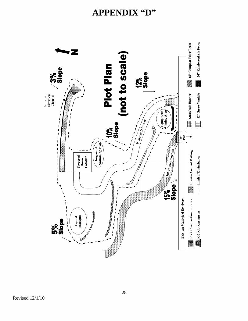
Please refer to Appendices C and D (on pgs. 27 and 28) for sample “Plot Plan” drawings.
7 Revised 12/1/10
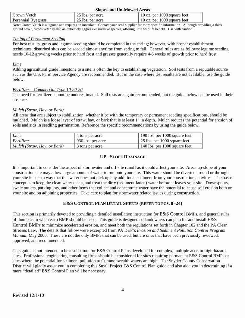
E
rosi
on a
nd S
edim
ent C
ontr
ol P
lot P
lan
Lege
nd a
nd S
ymbo
ls
Pr
ojec
t Nam
e:
D
evel
oped
By:
Mun
icip
ality
:
Dat
e:
8 Revised 12/1/10
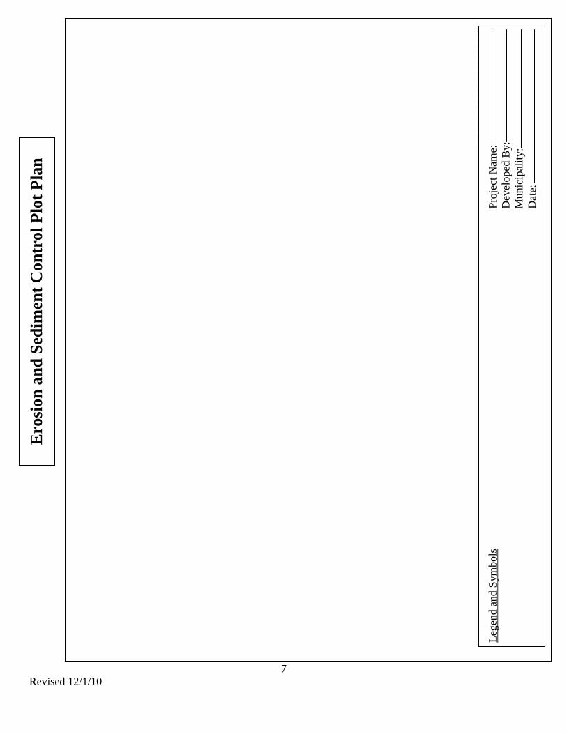
STANDARD CONSTRUCTION DETAIL # 3-1
Rock Construction Entrance
Topsoil should be removed prior to installation of Rock Construction Entrance. Extend rock over full width of entrance. Runoff shall be diverted from roadway to a suitable sediment removal BMP prior to entering Rock Construction Entrance. Mountable berm should be installed wherever optional culvert pipe is used. Pipe to be sized appropriately for size of ditch being crossed. MAINTENANCE: Rock Construction Entrance thickness shall be constantly maintained to the specified dimensions by adding rock. A stockpile shall be maintained on site for this purpose. All sediment deposited on paved roadways shall be removed and returned to the construction site immediately. If excessive amounts of sediment are being deposited on roadway, extend length of Rock Construction Entrance by 50 feet increments until condition is alleviated or install wash rack. Washing the roadway or sweeping the deposits into roadway ditches, sewer, culverts, or other drainageways is not acceptable.
9 Revised 12/1/10
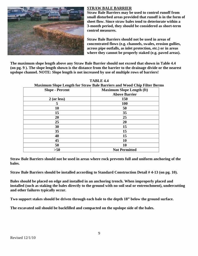
STRAW BALE BARRIER Straw Bale Barriers may be used to control runoff from small disturbed areas provided that runoff is in the form of sheet flow. Since straw bales tend to deteriorate within a 3-month period, they should be considered as short-term control measures.
Straw Bale Barriers should not be used in areas of concentrated flows (e.g. channels, swales, erosion gullies, across pipe outfalls, as inlet protection, etc.) or in areas where they cannot be properly staked (e.g. paved areas).
The maximum slope length above any Straw Bale Barrier should not exceed that shown in Table 4.4 (on pg. 9 ). The slope length shown is the distance from the barrier to the drainage divide or the nearest upslope channel. NOTE: Slope length is not increased by use of multiple rows of barriers!
TABLE 4.4 Maximum Slope Length for Straw Bale Barriers and Wood Chip Filter Berms
Slope - Percent
Maximum Slope Length (ft) Above Barrier
2 (or less) 150 5 100 10 50 15 35 20 25 25 20 30 15 35 15 40 15 45 10 50 10
>50 Not Permitted Straw Bale Barriers should not be used in areas where rock prevents full and uniform anchoring of the bales. Straw Bale Barriers should be installed according to Standard Construction Detail # 4-13 (on pg. 10). Bales should be placed on edge and installed in an anchoring trench. When improperly placed and installed (such as staking the bales directly to the ground with no soil seal or entrenchment), undercutting and other failures typically occur. Two support stakes should be driven through each bale to the depth 18” below the ground surface.
The excavated soil should be backfilled and compacted on the upslope side of the bales.
10 Revised 12/1/10
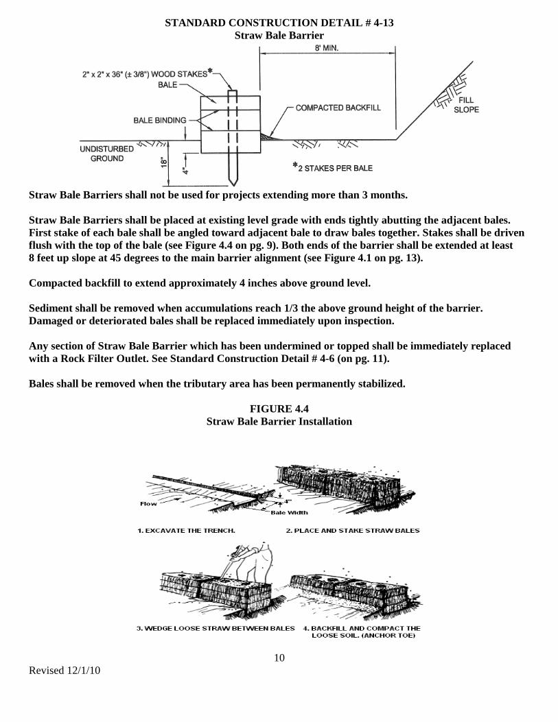
STANDARD CONSTRUCTION DETAIL # 4-13 Straw Bale Barrier
Straw Bale Barriers shall not be used for projects extending more than 3 months. Straw Bale Barriers shall be placed at existing level grade with ends tightly abutting the adjacent bales. First stake of each bale shall be angled toward adjacent bale to draw bales together. Stakes shall be driven flush with the top of the bale (see Figure 4.4 on pg. 9). Both ends of the barrier shall be extended at least 8 feet up slope at 45 degrees to the main barrier alignment (see Figure 4.1 on pg. 13). Compacted backfill to extend approximately 4 inches above ground level. Sediment shall be removed when accumulations reach 1/3 the above ground height of the barrier. Damaged or deteriorated bales shall be replaced immediately upon inspection. Any section of Straw Bale Barrier which has been undermined or topped shall be immediately replaced with a Rock Filter Outlet. See Standard Construction Detail # 4-6 (on pg. 11). Bales shall be removed when the tributary area has been permanently stabilized.
FIGURE 4.4 Straw Bale Barrier Installation
11 Revised 12/1/10
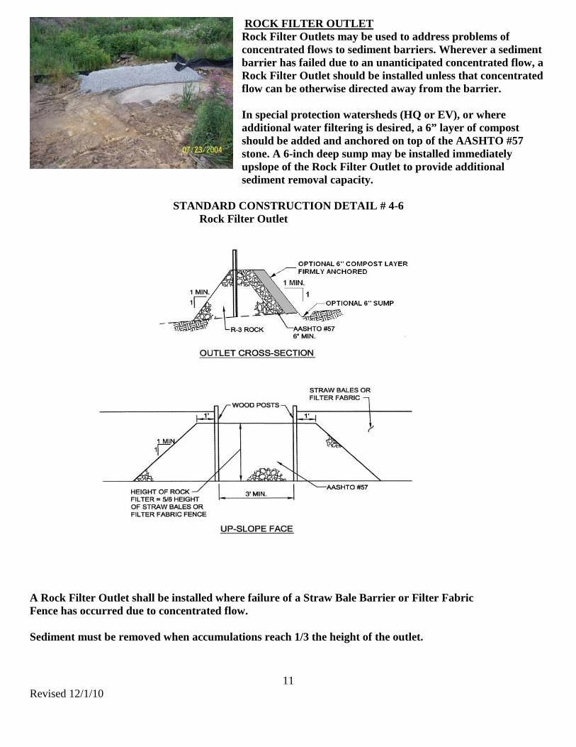
ROCK FILTER OUTLET Rock Filter Outlets may be used to address problems of concentrated flows to sediment barriers. Wherever a sediment barrier has failed due to an unanticipated concentrated flow, a Rock Filter Outlet should be installed unless that concentrated flow can be otherwise directed away from the barrier. In special protection watersheds (HQ or EV), or where additional water filtering is desired, a 6” layer of compost should be added and anchored on top of the AASHTO #57 stone. A 6-inch deep sump may be installed immediately upslope of the Rock Filter Outlet to provide additional
sediment removal capacity.
STANDARD CONSTRUCTION DETAIL # 4-6 Rock Filter Outlet
A Rock Filter Outlet shall be installed where failure of a Straw Bale Barrier or Filter Fabric Fence has occurred due to concentrated flow. Sediment must be removed when accumulations reach 1/3 the height of the outlet.
12 Revised 12/1/10
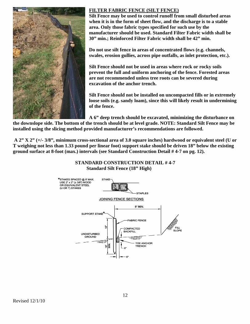
FILTER FABRIC FENCE (SILT FENCE) Silt Fence may be used to control runoff from small disturbed areas when it is in the form of sheet flow, and the discharge is to a stable area. Only those fabric types specified for such use by the manufacturer should be used. Standard Filter Fabric width shall be 30” min.; Reinforced Filter Fabric width shall be 42” min. Do not use silt fence in areas of concentrated flows (e.g. channels, swales, erosion gullies, across pipe outfalls, as inlet protection, etc.). Silt Fence should not be used in areas where rock or rocky soils prevent the full and uniform anchoring of the fence. Forested areas are not recommended unless tree roots can be severed during excavation of the anchor trench. Silt Fence should not be installed on uncompacted fills or in extremely loose soils (e.g. sandy loam), since this will likely result in undermining of the fence. A 6” deep trench should be excavated, minimizing the disturbance on
the downslope side. The bottom of the trench should be at level grade. NOTE: Standard Silt Fence may be installed using the slicing method provided manufacturer’s recommendations are followed. A 2” X 2” (+/- 3/8”, minimum cross-sectional area of 3.0 square inches) hardwood or equivalent steel (U or T weighing not less than 1.33 pound per linear foot) support stake should be driven 18” below the existing ground surface at 8-foot (max.) intervals (see Standard Construction Detail # 4-7 on pg. 12).
STANDARD CONSTRUCTION DETAIL # 4-7 Standard Silt Fence (18” High)
13 Revised 12/1/10
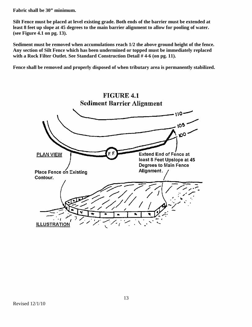
Fabric shall be 30” minimum. Silt Fence must be placed at level existing grade. Both ends of the barrier must be extended at least 8 feet up slope at 45 degrees to the main barrier alignment to allow for pooling of water. (see Figure 4.1 on pg. 13). Sediment must be removed when accumulations reach 1/2 the above ground height of the fence. Any section of Silt Fence which has been undermined or topped must be immediately replaced with a Rock Filter Outlet. See Standard Construction Detail # 4-6 (on pg. 11). Fence shall be removed and properly disposed of when tributary area is permanently stabilized.

14 Revised 12/1/10
STANDARD CONSTRUCTION DETAIL # 4-8
Reinforced Silt Fence (30” High)
Fabric shall be 42” minimum. Silt Fence must be installed at existing level grade. Both ends of each fence section must be extended at least 8 feet upslope at 45 degrees to the main fence alignment (see Figure 4.1 on pg. 13). Sediment must be removed where accumulations reach 1/ 2 the above ground height of the fence. Any section of Silt Fence which has been undermined or topped must be immediately replaced with a Rock Filter Outlet. See Standard Construction Detail # 4-6 (on pg. 11). Fence shall be removed and properly disposed of when tributary area is permanently stabilized.
STANDARD CONSTRUCTION DETAIL # 4-9
Silt Fence Reinforced by Staked Straw Bales
15 Revised 12/1/10
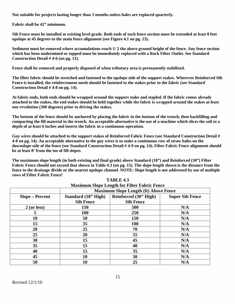
Not suitable for projects lasting longer than 3 months unless bales are replaced quarterly. Fabric shall be 42” minimum. Silt Fence must be installed at existing level grade. Both ends of each fence section must be extended at least 8 feet upslope at 45 degrees to the main fence alignment (see Figure 4.1 on pg. 13). Sediment must be removed where accumulations reach 1/ 2 the above ground height of the fence. Any fence section which has been undermined or topped must be immediately replaced with a Rock Filter Outlet. See Standard Construction Detail # 4-6 (on pg. 11). Fence shall be removed and properly disposed of when tributary area is permanently stabilized. The filter fabric should be stretched and fastened to the upslope side of the support stakes. Wherever Reinforced Silt Fence is installed, the reinforcement mesh should be fastened to the stakes prior to the fabric (see Standard Construction Detail # 4-8 on pg. 14). At fabric ends, both ends should be wrapped around the support stake and stapled. If the fabric comes already attached to the stakes, the end stakes should be held together while the fabric is wrapped around the stakes at least one revolution (360 degrees) prior to driving the stakes. The bottom of the fence should be anchored by placing the fabric in the bottom of the trench, then backfilling and compacting the fill material in the trench. An acceptable alternative is the use of a machine which slices the soil to a depth of at least 6 inches and inserts the fabric in a continuous operation. Guy wires should be attached to the support stakes of Reinforced Fabric Fence (see Standard Construction Detail # 4-8 on pg. 14). An acceptable alternative to the guy wires is to stake a continuous row of straw bales on the downslope side of the fence (see Standard Construction Detail # 4-9 on pg. 14). Filter Fabric Fence alignment should be at least 8’ from the toe of fill slopes. The maximum slope length (in both existing and final grade) above Standard (18”) and Reinforced (30”) Filter Fabric Fence should not exceed that shown in Table 4.3 (on pg. 15). The slope length shown is the distance from the fence to the drainage divide or the nearest upslope channel. NOTE: Slope length is not addressed by use of multiple rows of Filter Fabric Fence!
TABLE 4.3 Maximum Slope Length for Filter Fabric Fence
Maximum Slope Length (ft) Above Fence Slope – Percent Standard (18” High)
Silt Fence Reinforced (30” High)
Silt Fence Super Silt Fence
2 (or less) 150 500 N/A 5 100 250 N/A 10 50 150 N/A 15 35 100 N/A 20 25 70 N/A 25 20 55 N/A 30 15 45 N/A 35 15 40 N/A 40 15 35 N/A 45 10 30 N/A 50 10 25 N/A
16 Revised 12/1/10
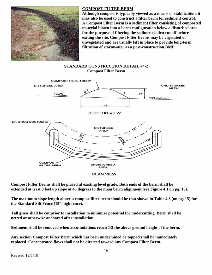
COMPOST FILTER BERM Although compost is typically viewed as a means of stabilization, it may also be used to construct a filter berm for sediment control. A Compost Filter Berm is a sediment filter consisting of composted material blown into a berm configuration below a disturbed area for the purpose of filtering the sediment-laden runoff before exiting the site. Compost Filter Berms may be vegetated or unvegetated and are usually left in place to provide long-term filtration of stormwater as a post-construction BMP.
STANDARD CONSTRUCTION DETAIL #4-2 Compost Filter Berm
Compost Filter Berms shall be placed at existing level grade. Both ends of the berm shall be extended at least 8 feet up slope at 45 degrees to the main berm alignment (see Figure 4.1 on pg. 13). The maximum slope length above a compost filter berm should be that shown in Table 4.3 (on pg. 15) for the Standard Silt Fence (18” high fence). Tall grass shall be cut prior to installation to minimize potential for undercutting. Berm shall be netted or otherwise anchored after installation. Sediment shall be removed when accumulations reach 1/3 the above ground height of the berm. Any section Compost Filter Berm which has been undermined or topped shall be immediately replaced. Concentrated flows shall not be directed toward any Compost Filter Berm.
17 Revised 12/1/10
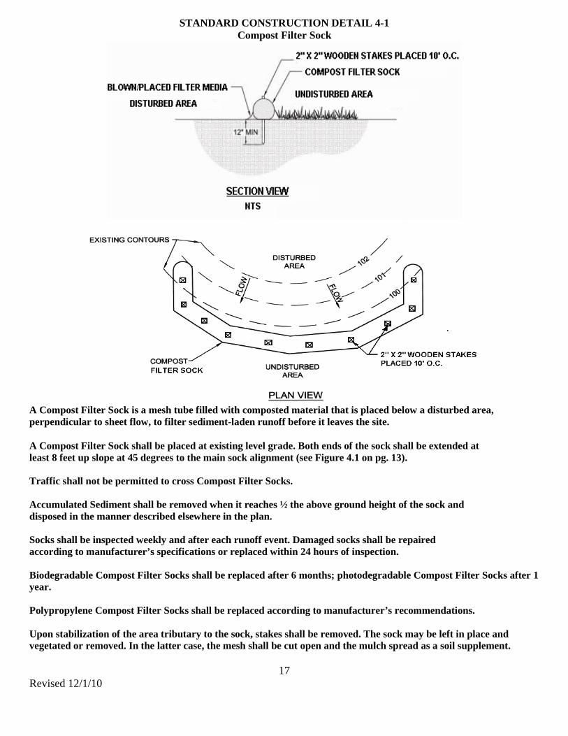
STANDARD CONSTRUCTION DETAIL 4-1 Compost Filter Sock
A Compost Filter Sock is a mesh tube filled with composted material that is placed below a disturbed area, perpendicular to sheet flow, to filter sediment-laden runoff before it leaves the site. A Compost Filter Sock shall be placed at existing level grade. Both ends of the sock shall be extended at least 8 feet up slope at 45 degrees to the main sock alignment (see Figure 4.1 on pg. 13). Traffic shall not be permitted to cross Compost Filter Socks. Accumulated Sediment shall be removed when it reaches ½ the above ground height of the sock and disposed in the manner described elsewhere in the plan. Socks shall be inspected weekly and after each runoff event. Damaged socks shall be repaired according to manufacturer’s specifications or replaced within 24 hours of inspection. Biodegradable Compost Filter Socks shall be replaced after 6 months; photodegradable Compost Filter Socks after 1 year. Polypropylene Compost Filter Socks shall be replaced according to manufacturer’s recommendations. Upon stabilization of the area tributary to the sock, stakes shall be removed. The sock may be left in place and vegetated or removed. In the latter case, the mesh shall be cut open and the mulch spread as a soil supplement.
18 Revised 12/1/10
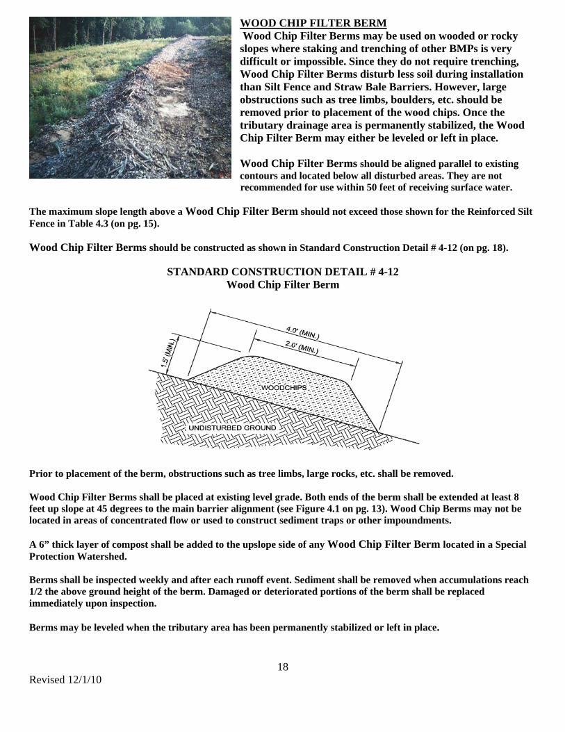
WOOD CHIP FILTER BERM Wood Chip Filter Berms may be used on wooded or rocky slopes where staking and trenching of other BMPs is very difficult or impossible. Since they do not require trenching, Wood Chip Filter Berms disturb less soil during installation than Silt Fence and Straw Bale Barriers. However, large obstructions such as tree limbs, boulders, etc. should be removed prior to placement of the wood chips. Once the tributary drainage area is permanently stabilized, the Wood Chip Filter Berm may either be leveled or left in place. Wood Chip Filter Berms should be aligned parallel to existing contours and located below all disturbed areas. They are not
recommended for use within 50 feet of receiving surface water. The maximum slope length above a Wood Chip Filter Berm should not exceed those shown for the Reinforced Silt Fence in Table 4.3 (on pg. 15). Wood Chip Filter Berms should be constructed as shown in Standard Construction Detail # 4-12 (on pg. 18).
STANDARD CONSTRUCTION DETAIL # 4-12 Wood Chip Filter Berm
Prior to placement of the berm, obstructions such as tree limbs, large rocks, etc. shall be removed. Wood Chip Filter Berms shall be placed at existing level grade. Both ends of the berm shall be extended at least 8 feet up slope at 45 degrees to the main barrier alignment (see Figure 4.1 on pg. 13). Wood Chip Berms may not be located in areas of concentrated flow or used to construct sediment traps or other impoundments. A 6” thick layer of compost shall be added to the upslope side of any Wood Chip Filter Berm located in a Special Protection Watershed. Berms shall be inspected weekly and after each runoff event. Sediment shall be removed when accumulations reach 1/2 the above ground height of the berm. Damaged or deteriorated portions of the berm shall be replaced immediately upon inspection. Berms may be leveled when the tributary area has been permanently stabilized or left in place.

19 Revised 12/1/10
ROCK FILTER Rock Filters may be used to control runoff within constructed channels (at the downstream end of the channel, during construction) until the protective lining is installed or during a temporary disturbance within the channel. Rock Filters may not be used to control disturbed areas tributary to the channel in which they are placed. Rock Filters may not be used in lieu of appropriate channel linings. This practice often results in overtopping of the channel during storm events, scouring of the channel bottom below the filter, or erosion of
the channel side slopes as sediment deposits build up behind the filter. Rock Filters may not be used in roadside ditches in lieu of a suitable temporary protective liner until vegetation is established except at the inflows to ditch relief culverts. Ditch relief culverts reduce road sediment delivery to nearby streams by diverting sediment-laden ditch water onto stabilized areas (i.e. such as a forest floor) where it can infiltrate and be filtered. Rock Filters should be constructed according to the specifications shown in Standard Construction Detail # 4-14 (on pg. 20). Rock Filters should be constructed with Rip-rap sized as follows: (see Chart RRSC #1 on pg. 19)
• For channels with Total Depth > 3 feet, use R-4. • For channels with Total Depth between 2 and 3 feet, use R-3.
Rock Filters should not be used in channels of less than 2 feet total depth and they should be equal in height to ½ the total depth of the channel with a 6” depression in the center. A one foot thick layer of AASHTO #57 (i.e. 2B stone) or smaller should be placed on the upstream side of the filter. In special protection watersheds, a 6” layer of compost should be placed and anchored on top of the filter stone. NOTE: Filter fabric and straw bales should not be used in Rock Filters! Rock Filters should be inspected weekly and after each runoff event. Clogged filter stone (AASHTO # 57) should be replaced and needed repairs be initiated after the inspection.
RIP – RAP (R) SIZING CHART - RRSC #1 American Association of State Highway and Transportation Officials (AASHTO)
Rock Size R-3 R-4 R-5 R-6 R-7 R-8 2” 0-15% 3” 15-50% 0-15% 4” 0-15% 6” 100% 15-50% 9” 15-50% 0-15%
12” 100% 0-15% 15” 15-50% 0-15% 18” 100% 15-50% 24” 100% 15-50% 30” 100% 42” 100%
Minimum Thickness
12” 18” 24” 30” 36” 48”
20 Revised 12/1/10
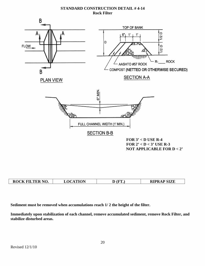
STANDARD CONSTRUCTION DETAIL # 4-14 Rock Filter
FOR 3’ < D USE R-4
FOR 2’ < D < 3’ USE R-3 NOT APPLICABLE FOR D < 2’
ROCK FILTER NO. LOCATION D (FT.) RIPRAP SIZE
Sediment must be removed when accumulations reach 1/ 2 the height of the filter. Immediately upon stabilization of each channel, remove accumulated sediment, remove Rock Filter, and stabilize disturbed areas.
21 Revised 12/1/10
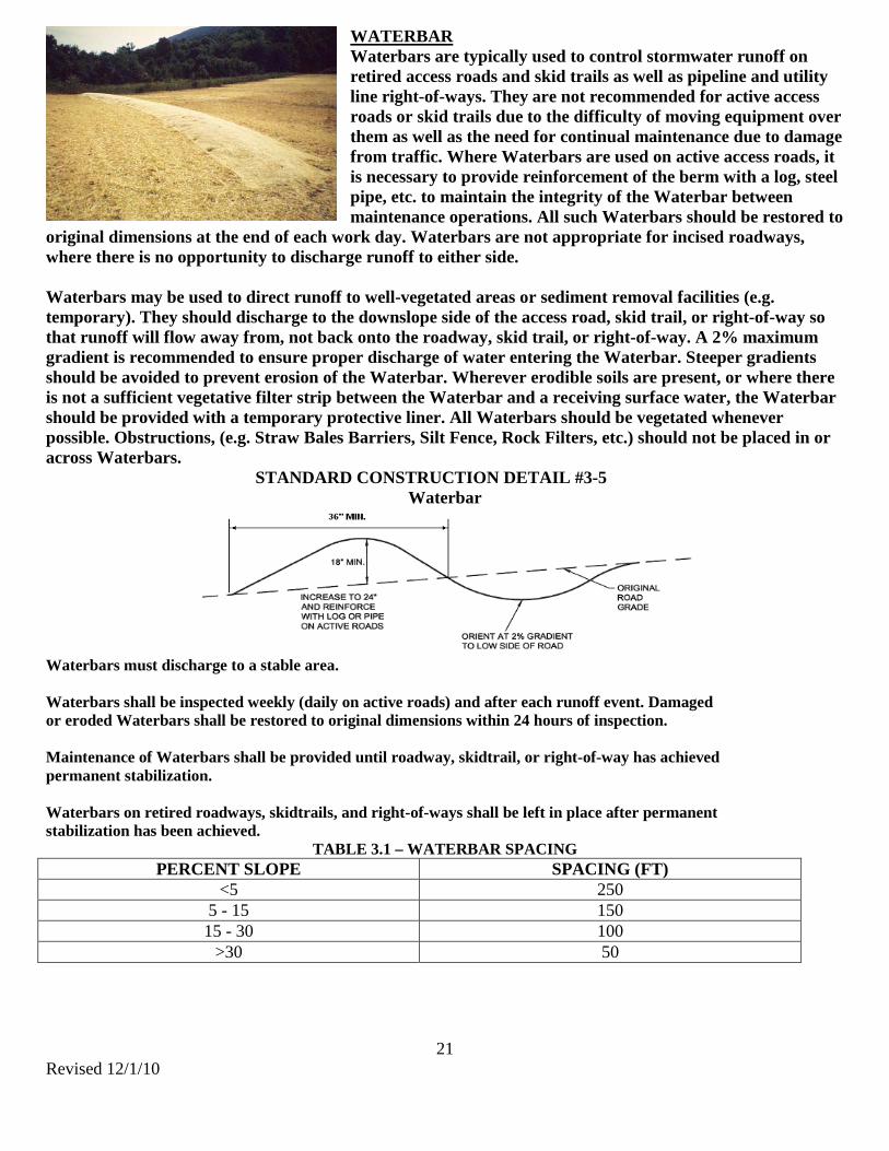
WATERBAR Waterbars are typically used to control stormwater runoff on retired access roads and skid trails as well as pipeline and utility line right-of-ways. They are not recommended for active access roads or skid trails due to the difficulty of moving equipment over them as well as the need for continual maintenance due to damage from traffic. Where Waterbars are used on active access roads, it is necessary to provide reinforcement of the berm with a log, steel pipe, etc. to maintain the integrity of the Waterbar between maintenance operations. All such Waterbars should be restored to
original dimensions at the end of each work day. Waterbars are not appropriate for incised roadways, where there is no opportunity to discharge runoff to either side. Waterbars may be used to direct runoff to well-vegetated areas or sediment removal facilities (e.g. temporary). They should discharge to the downslope side of the access road, skid trail, or right-of-way so that runoff will flow away from, not back onto the roadway, skid trail, or right-of-way. A 2% maximum gradient is recommended to ensure proper discharge of water entering the Waterbar. Steeper gradients should be avoided to prevent erosion of the Waterbar. Wherever erodible soils are present, or where there is not a sufficient vegetative filter strip between the Waterbar and a receiving surface water, the Waterbar should be provided with a temporary protective liner. All Waterbars should be vegetated whenever possible. Obstructions, (e.g. Straw Bales Barriers, Silt Fence, Rock Filters, etc.) should not be placed in or across Waterbars.
STANDARD CONSTRUCTION DETAIL #3-5 Waterbar
Waterbars must discharge to a stable area. Waterbars shall be inspected weekly (daily on active roads) and after each runoff event. Damaged or eroded Waterbars shall be restored to original dimensions within 24 hours of inspection. Maintenance of Waterbars shall be provided until roadway, skidtrail, or right-of-way has achieved permanent stabilization. Waterbars on retired roadways, skidtrails, and right-of-ways shall be left in place after permanent stabilization has been achieved.
TABLE 3.1 – WATERBAR SPACING PERCENT SLOPE SPACING (FT)
<5 250 5 - 15 150 15 - 30 100
>30 50
22 Revised 12/1/10
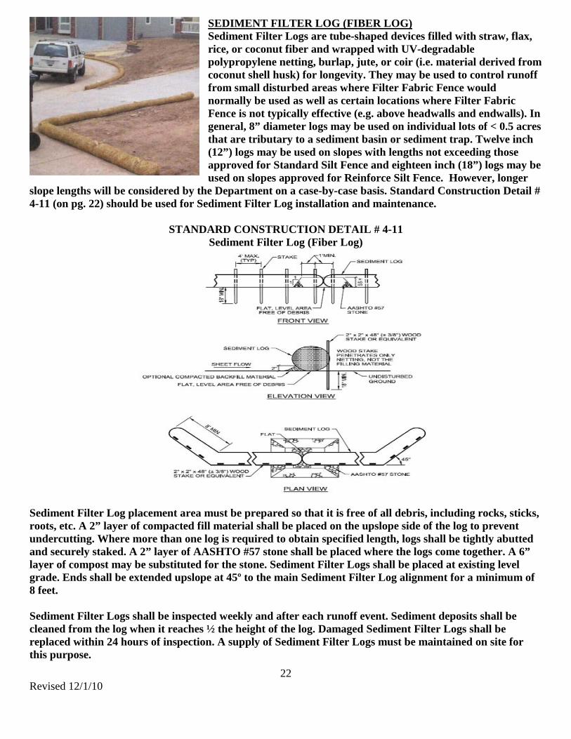
SEDIMENT FILTER LOG (FIBER LOG) Sediment Filter Logs are tube-shaped devices filled with straw, flax, rice, or coconut fiber and wrapped with UV-degradable polypropylene netting, burlap, jute, or coir (i.e. material derived from coconut shell husk) for longevity. They may be used to control runoff from small disturbed areas where Filter Fabric Fence would normally be used as well as certain locations where Filter Fabric Fence is not typically effective (e.g. above headwalls and endwalls). In general, 8” diameter logs may be used on individual lots of < 0.5 acres that are tributary to a sediment basin or sediment trap. Twelve inch (12”) logs may be used on slopes with lengths not exceeding those approved for Standard Silt Fence and eighteen inch (18”) logs may be used on slopes approved for Reinforce Silt Fence. However, longer
slope lengths will be considered by the Department on a case-by-case basis. Standard Construction Detail # 4-11 (on pg. 22) should be used for Sediment Filter Log installation and maintenance.
STANDARD CONSTRUCTION DETAIL # 4-11 Sediment Filter Log (Fiber Log)
Sediment Filter Log placement area must be prepared so that it is free of all debris, including rocks, sticks, roots, etc. A 2” layer of compacted fill material shall be placed on the upslope side of the log to prevent undercutting. Where more than one log is required to obtain specified length, logs shall be tightly abutted and securely staked. A 2” layer of AASHTO #57 stone shall be placed where the logs come together. A 6” layer of compost may be substituted for the stone. Sediment Filter Logs shall be placed at existing level grade. Ends shall be extended upslope at 45º to the main Sediment Filter Log alignment for a minimum of 8 feet. Sediment Filter Logs shall be inspected weekly and after each runoff event. Sediment deposits shall be cleaned from the log when it reaches ½ the height of the log. Damaged Sediment Filter Logs shall be replaced within 24 hours of inspection. A supply of Sediment Filter Logs must be maintained on site for this purpose.
23 Revised 12/1/10
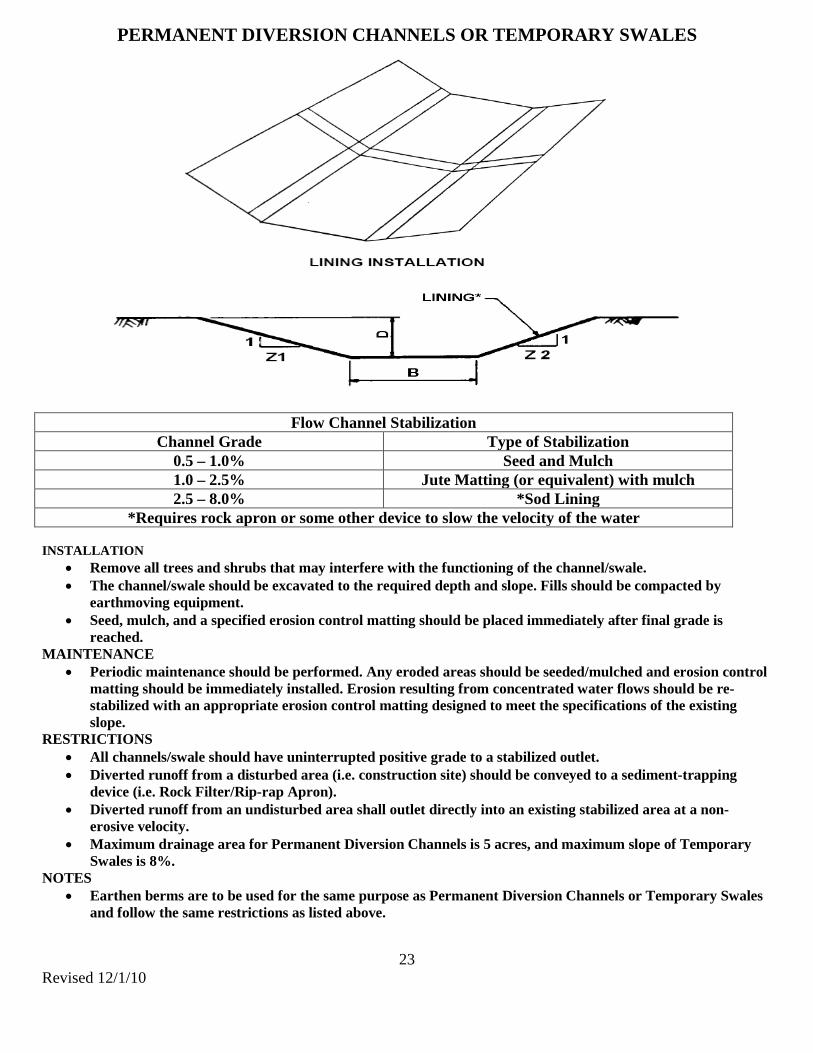
PERMANENT DIVERSION CHANNELS OR TEMPORARY SWALES
Flow Channel Stabilization Channel Grade Type of Stabilization
0.5 – 1.0% Seed and Mulch 1.0 – 2.5% Jute Matting (or equivalent) with mulch 2.5 – 8.0% *Sod Lining
*Requires rock apron or some other device to slow the velocity of the water INSTALLATION
• Remove all trees and shrubs that may interfere with the functioning of the channel/swale. • The channel/swale should be excavated to the required depth and slope. Fills should be compacted by
earthmoving equipment. • Seed, mulch, and a specified erosion control matting should be placed immediately after final grade is
reached. MAINTENANCE
• Periodic maintenance should be performed. Any eroded areas should be seeded/mulched and erosion control matting should be immediately installed. Erosion resulting from concentrated water flows should be re-stabilized with an appropriate erosion control matting designed to meet the specifications of the existing slope.
RESTRICTIONS • All channels/swale should have uninterrupted positive grade to a stabilized outlet. • Diverted runoff from a disturbed area (i.e. construction site) should be conveyed to a sediment-trapping
device (i.e. Rock Filter/Rip-rap Apron). • Diverted runoff from an undisturbed area shall outlet directly into an existing stabilized area at a non-
erosive velocity. • Maximum drainage area for Permanent Diversion Channels is 5 acres, and maximum slope of Temporary
Swales is 8%. NOTES
• Earthen berms are to be used for the same purpose as Permanent Diversion Channels or Temporary Swales and follow the same restrictions as listed above.
24 Revised 12/1/10
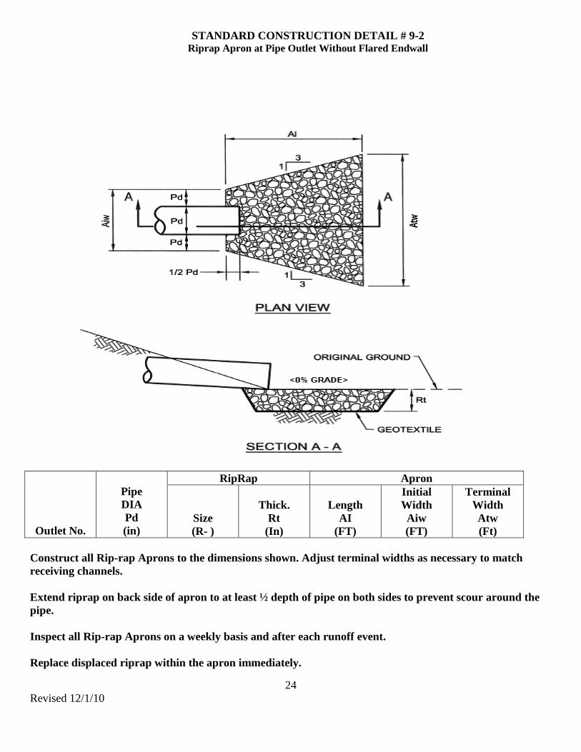
STANDARD CONSTRUCTION DETAIL # 9-2
Riprap Apron at Pipe Outlet Without Flared Endwall
Outlet No.
Pipe DIA Pd (in)
RipRap Apron
Size (R- )
Thick.
Rt (In)
Length
AI (FT)
Initial Width Aiw (FT)
Terminal Width Atw (Ft)
Construct all Rip-rap Aprons to the dimensions shown. Adjust terminal widths as necessary to match receiving channels. Extend riprap on back side of apron to at least ½ depth of pipe on both sides to prevent scour around the pipe. Inspect all Rip-rap Aprons on a weekly basis and after each runoff event. Replace displaced riprap within the apron immediately.
25 Revised 12/1/10
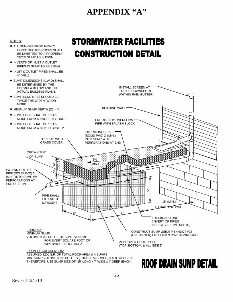
APPENDIX “A”
INSTALL SCREEN AT TOP OF DOWNSPOUT (WITHIN RAIN GUTTER)
BUILDING WALL
EMERGENCY OVERFLOW PIPE WITH SPLASH BLOCK
EXTEND INLET PIPE (SOLID PVC) 2’ (MIN.) INTO SUMP WITH PERFORATIONS AT END
TOP SOIL WITH GRASS COVER
NOTES:
• ALL RUN-OFF FROM NEWLY CONSTRUCTED ROOFS SHALL BE DIVERTED TO A PROPERLY SIZED SUMP AS SHOWN.
• INVERTS OF INLET & OUTLET PIPES IN SUMP TO BE EQUAL
• INLET & OUTLET PIPES SHALL BE 4” (MIN.)
• SUMP DIMENSIONS (L,W,D) SHALL BE DETERMINED BY THE FORMULA BELOW AND THE ACTUAL BUILDING PLANS.
• SUMP LENGTH (L) SHOULD BE TWICE THE WIDTH (W) OR MORE.
• MINIMUM SUMP DEPTH (D) = 4’.
• SUMP EDGE SHALL BE 10’ OR MORE FROM A PROPERTY LINE.
• SUMP EDGE SHALL BE 15’ OR MORE FROM A SEPTIC SYSTEM.
CROWN/TOP OF SUMP
12
” C
OV
ER
4”
PIPE SHALL EXTEND TO DAYLIGHT
EXTEND OUTLET PIPE (SOLID PVC) 2’ (MIN.) INTO SUMP W/ PERFORATIONS AT END OF SUMP
L’ W’
D’
FORMULA: MINIMUM SUMP VOLUME = 0.5 CU. FT. OF SUMP VOLUME FOR EVERY SQUARE FOOT OF IMPERVIOUS ROOF AREA EXAMPLE CALCULATION; ASSUMED 3200 S.F. OF TOTAL ROOF AREA & 4 SUMPS MIN. SUMP VOLUME = 0.5 CU. FT. x (3200 S.F./4 SUMPS) = 400 CU.FT./EA. THEREFORE, USE SUMP SIZE OF: 15’ LONG x 7’ WIDE x 4’ DEEP (EACH)
APPROVED GEOTEXTILE (TOP, BOTTOM, & ALL SIDES)
CONSTRUCT SUMP USING PENNDOT #2B (OR LARGER) CRUSHED STONE AGGREGATE
FREEBOARD UNIT (INVERT OF PIPES EFFECTIVE SUMP DEPTH)
15’ (MIN.)
TO BUILDING WALL
2% (MIN.)
26 Revised 12/1/10
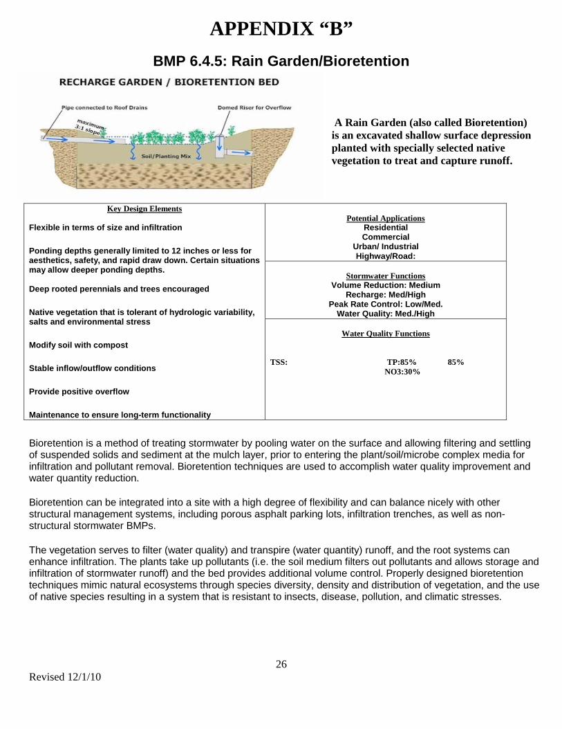
APPENDIX “B”
BMP 6.4.5: Rain Garden/Bioretention A Rain Garden (also called Bioretention) is an excavated shallow surface depression planted with specially selected native vegetation to treat and capture runoff.
Key Design Elements
Flexible in terms of size and infiltration Ponding depths generally limited to 12 inches or less for aesthetics, safety, and rapid draw down. Certain situations may allow deeper ponding depths. Deep rooted perennials and trees encouraged Native vegetation that is tolerant of hydrologic variability, salts and environmental stress Modify soil with compost Stable inflow/outflow conditions Provide positive overflow Maintenance to ensure long-term functionality
Potential Applications
Residential Commercial
Urban/ Industrial Highway/Road:
Stormwater Functions
Volume Reduction: Medium Recharge: Med/High
Peak Rate Control: Low/Med. Water Quality: Med./High
Water Quality Functions
TSS: TP:85% 85% NO3:30%
Bioretention is a method of treating stormwater by pooling water on the surface and allowing filtering and settling of suspended solids and sediment at the mulch layer, prior to entering the plant/soil/microbe complex media for infiltration and pollutant removal. Bioretention techniques are used to accomplish water quality improvement and water quantity reduction. Bioretention can be integrated into a site with a high degree of flexibility and can balance nicely with other structural management systems, including porous asphalt parking lots, infiltration trenches, as well as non-structural stormwater BMPs. The vegetation serves to filter (water quality) and transpire (water quantity) runoff, and the root systems can enhance infiltration. The plants take up pollutants (i.e. the soil medium filters out pollutants and allows storage and infiltration of stormwater runoff) and the bed provides additional volume control. Properly designed bioretention techniques mimic natural ecosystems through species diversity, density and distribution of vegetation, and the use of native species resulting in a system that is resistant to insects, disease, pollution, and climatic stresses.
27 Revised 12/1/10
APPENDIX “C”
28 Revised 12/1/10
APPENDIX “D”
29 Revised 12/1/10
GLOSSARY Aggregate -----Hard, tough, durable, particles, reasonably free from silt, clay, & vegetation. Coarse aggregates (those retained on a No. 4 sieve) are often used as filter stone. Apron -----A covering along a shoreline or immediately below a pipe or channel outfall for protection against erosion. Best Management Practice (BMP) -----A generally accepted practice for minimizing accelerated erosion and resultant sediment pollution to protect, maintain, reclaim and restore the quality of waters and the existing and designated uses of waters within this Commonwealth. Channel Lining ----- The material applied to the bottom and/or sides of a natural or constructed channel to prevent or minimize abrasion, scour and other forms of erosion. Disturbed Area -----That part of an earth disturbance project from which the vegetative cover has been removed to the extent that the potential for accelerated erosion exists. Drainage Area -----The area above a BMP from which runoff would normally drain to that BMP. Geotextile -----A fabric manufactured from synthetic fiber (usually non-biodegradable, either woven or non-woven) that is designed to achieve specific engineering objectives, including seepage control, separation of materials, filtration, or protection of other construction materials. Grubbing -----The operation of removing stumps and roots. Mulch -----A natural or artificial layer of plant residue or other materials placed on the soil surface to protect seeds, prevent blowing, retain soil moisture, curtail erosion, aid in establishing plant cover, and and minimize soil temperature fluctuations. Outlet Protection -----An apron, dissipater, basin, or other device placed below a pipe or channel outfall to prevent scour. Riprap -----Crushed stone which meets certain requirements for size gradation, weight, durability, and shape. It is generally specified according to “R” size. Temporary Stabilization ----- Provision of immediate protection from accelerated erosion pending future disturbance, typically in the form of annual seed mixtures and/or mulch. Thank-You-Ma’am -----Waterbar. Waterbar -----A low berm constructed at an angle across the right-of-way of a pipeline or utility line to direct runoff away from the right-of-way onto a well-vegetated area.