Simplified representation of concrete reinforcement
32
BRITISH STANDARD BS EN ISO 3766:2003 Incorporating Corrigendum No. 1 Construction drawings — Simplified representation of concrete reinforcement The European Standard EN ISO 3766:2003 has the status of a British Standard ICS 01.100.30
-
Upload
trinhkhuong -
Category
Documents
-
view
232 -
download
8
Transcript of Simplified representation of concrete reinforcement

BRITISH STANDARD BS EN ISO 3766:2003 Incorporating Corrigendum No. 1
Construction drawings — Simplified representation of concrete reinforcement
The European Standard EN ISO 3766:2003 has the status of a British Standard
ICS 01.100.30
���������������� ������������������������������� �������������

BS EN ISO 3766:2003
This British Standard was published under the authority of the Standards Policy and Strategy Committee on 13 May 2004
© BSI 14 February 2005
ISBN 0 580 43766 3
National forewordThis British Standard is the official English language version of EN ISO 3766:2003, including Corrigendum September 2004. It is identical with ISO 3766:2003. It supersedes BS EN ISO 3766:1999 and BS EN ISO 4066:2000 which are withdrawn.
The UK participation in its preparation was entrusted to Technical Committee B/555, Construction design, modelling and data exchange, which has the responsibility to:
A list of organizations represented on this committee can be obtained on request to its secretary.
Cross-referencesThe British Standards which implement international or European publications referred to in this document may be found in the BSI Catalogue under the section entitled “International Standards Correspondence Index”, or by using the “Search” facility of the BSI Electronic Catalogue or of British Standards Online.
This publication does not purport to include all the necessary provisions of a contract. Users are responsible for its correct application.
Compliance with a British Standard does not of itself confer immunity from legal obligations.
— aid enquirers to understand the text;
— present to the responsible international/European committee any enquiries on the interpretation, or proposals for change, and keep the UK interests informed;
— monitor related international and European developments and promulgate them in the UK.
Summary of pages
This document comprises a front cover, an inside front cover, the EN ISO title page, the EN ISO foreword page, the ISO title page, pages ii to iv, pages 1 to 22, an inside back cover and a back cover.
The BSI copyright notice displayed in this document indicates when the document was last issued.
Amendments issued since publication
Amd. No. Date Comments
15521 Corrigendum No. 1
14 February 2005 Addition to supersession details
EUROPEAN STANDARD
NORME EUROPÉENNE
EUROPÄISCHE NORM
EN ISO 3766
December 2003
ICS 01.100.30 Supersedes EN ISO 3766:1999 and EN ISO 4066:1999
Incorporating corrigendum September 2004
English version
Construction drawings - Simplified representation of concrete reinforcement (ISO 3766:2003)
Dessins de construction - Représentation simplifiée des armatures de béton (ISO 3766:2003)
Zeichnungen für das Bauwesen - Vereinfachte Darstellung von Bewehrungen (ISO 3766:2003)
This European Standard was approved by CEN on 3 November 2003. CEN members are bound to comply with the CEN/CENELEC Internal Regulations which stipulate the conditions for giving this European Standard the status of a national standard without any alteration. Up-to-date lists and bibliographical references concerning such national standards may be obtained on application to the Management Centre or to any CEN member. This European Standard exists in three official versions (English, French, German). A version in any other language made by translation under the responsibility of a CEN member into its own language and notified to the Management Centre has the same status as the official versions. CEN members are the national standards bodies of Austria, Belgium, Czech Republic, Denmark, Finland, France, Germany, Greece, Hungary, Iceland, Ireland, Italy, Luxembourg, Malta, Netherlands, Norway, Portugal, Slovakia, Spain, Sweden, Switzerland and United Kingdom.
EUROPEAN COMMITTEE FOR STANDARDIZATION C O M I T É E U R O P É E N D E N O R M A LI S A T I O NEUR OP ÄIS C HES KOM ITEE FÜR NOR M UNG
Management Centre: rue de Stassart, 36 B-1050 Brussels
© 2003 CEN All rights of exploitation in any form and by any means reserved worldwide for CEN national Members.
Ref. No. EN ISO 3766:2003 E
I NESO 73:6602( 30E)
2
CORRECTED 2004-03-03
Foreword
This document (EN ISO 3766:2003) has been prepared by Technical Committee ISO/TC 10"Technical drawings, product definition and related documentation" in collaboration with CMC.
This European Standard shall be given the status of a national standard, either by publication ofan identical text or by endorsement, at the latest by June 2004, and conflicting nationalstandards shall be withdrawn at the latest by June 2004.
This document supersedes EN ISO 3766:1999 and EN ISO 4066:1999.
According to the CEN/CENELEC Internal Regulations, the national standards organizations ofthe following countries are bound to implement this European Standard: Austria, Belgium, CzechRepublic, Denmark, Finland, France, Germany, Greece, Hungary, Iceland, Ireland, Italy,Luxembourg, Malta, Netherlands, Norway, Portugal, Slovakia, Spain, Sweden, Switzerland andthe United Kingdom.
Endorsement notice
The text of ISO 3766:2003 has been approved by CEN as EN ISO 3766:2003 without anymodifications.
EN ISO 3766:2003

Reference numberISO 3766:2003(E)
© OSI 3002
INTERNATIONAL STANDARD
ISO3766
Third edition2003-12-15
Construction drawings — Simplified representation of concrete reinforcement
Dessins de construction — Représentation simplifiée des armatures de béton
EN ISO 3766:2003

IS:6673 O3002(E)
DPlcsid Fremia ihTs PDF file mya ctnoian emdebt dedyfepcaes. In ccacnadrow eitA h'ebods licnesilop gnic,y tihs file mirp eb yatnde iv roweb detu slahl ton ide ebtlnu deess teh typfecaes wihce era hml era deddebicsnede ti dna onstlalde t noeh comuptfrep reromign tide ehtin.g In wodlnidaot gnihs fil,e trapise atpecc tiereht nser ehnopsiiblity fo nto ifnriigngn A'ebods licnesilop gnic.y ehT ISO tneClar Secrteirata caceptl on siibality in this .aera
Ai ebods a tedarmfo kra Aebod SystemI snctaropro.de
teDials fo teh sfotwcudorp erats sut deo crtaee tihs PDF file cna f ebi dnuon tlareneG eh Ifnler oatit evt oeh file; tP ehDc-Frtaeino marapterew stpo ereimizde fro irptni.gn Evyre cera neeb sah takne tsne oeru taht teh file is siutlbae fosu re yb ISO memdob rebeis. In tlnu ehikletneve y ttah lborp aem lertait gno it is f,dnuo plsaee ifnrom ttneC ehlar Secterirata ta teh serddaig sleb nevwo.
© ISO 3002 All irthgs erse.devr lnUeto sswrehise specified, on trap fo this lbupictaion maeb y cudorperro de tuilizi den yna form ro na ybm ynae,s lecetrinoc ro mceinahcla, incliduntohp gcoiypodna gn micrfoilm, wittuoh repmissii now nritign from ietI rehSa Ot tsserdda eh ebolw or IS'Os memreb i ydobn the cnuotfo yr ttseuqer ehe.r
ISO cirypothg fofice saCe tsopale 65 •eneG 1121-HC 02 avleT. 4 + 10 947 22 1 11 xaF0 947 22 14 + 9 74 E-mial [email protected] groWe bwww.is.o gro
ii © ISO– 3002 Allr ithgsr esedevr
EN ISO 3766:2003

IS:6673 O3002(E)
I ©SO – 3002 All irthgs ersedevr iii
Contents Page
Foreword............................................................................................................................................................ iv 1 Scope...................................................................................................................................................... 1 2 Normative references ........................................................................................................................... 1 3 Requirements to reinforcement construction drawings................................................................... 1 4 Placement information and representation........................................................................................ 2 4.1 Reinforcement without prestressing .................................................................................................. 2 4.2 Prestressed reinforcement................................................................................................................... 7 5 Marking................................................................................................................................................... 8 6 Bending information for unprestressed reinforcement bars ........................................................... 8 6.1 General ................................................................................................................................................... 8 6.2 Indication of bar shapes....................................................................................................................... 9 6.3 Coding system (optional) ................................................................................................................... 11 7 Bar schedule........................................................................................................................................ 17 7.1 General ................................................................................................................................................. 17 7.2 Shape schedule................................................................................................................................... 17 7.3 Bending schedule ............................................................................................................................... 17 7.4 Combined schedules .......................................................................................................................... 18 7.5 Title block............................................................................................................................................. 18 Annex A (informative) Mat schedule — Example .......................................................................................... 21
EN ISO 3766:2003

IS:6673 O3002(E)
iv I ©SO – 3002 All irthgs ersedevr
Foreword
ISO (the International Organization for Standardization) is a worldwide federation of national standards bodies (ISO member bodies). The work of preparing International Standards is normally carried out through ISO technical committees. Each member body interested in a subject for which a technical committee has been established has the right to be represented on that committee. International organizations, governmental and non-governmental, in liaison with ISO, also take part in the work. ISO collaborates closely with the International Electrotechnical Commission (IEC) on all matters of electrotechnical standardization.
International Standards are drafted in accordance with the rules given in the ISO/IEC Directives, Part 2.
The main task of technical committees is to prepare International Standards. Draft International Standards adopted by the technical committees are circulated to the member bodies for voting. Publication as an International Standard requires approval by at least 75 % of the member bodies casting a vote.
Attention is drawn to the possibility that some of the elements of this document may be the subject of patent rights. ISO shall not be held responsible for identifying any or all such patent rights.
ISO 3766 was prepared by Technical Committee ISO/TC 10, Technical product documentation, Subcommittee SC 8, Construction documentation.
This third edition cancels and replaces the second edition (ISO 3766:1995) and ISO 4066:1994, which have been technically revised.
EN ISO 3766:2003

INTENRATIONAL TSANDADR IS:6673 O3002(E)
I ©SO – 3002 All irthgs ersedevr 1
Construction drawings — Simplified representation of concrete reinforcement
1 Scope
This International Standard specifies the simplified representation and the characterization of reinforcement in reinforced and in prestressed concrete for use in construction drawings. It also establishes a system for the scheduling of reinforced bars, comprising
a method for specifying dimensions,
a coding system for bar shapes,
a schedule of preferred shapes, and
a shape schedule and bending schedule.
2 Normative references
The following referenced documents are indispensable for the application of this document. For dated references, only the edition cited applies. For undated references, the latest edition of the referenced document (including any amendments) applies.
ISO 128-23:1999, Technical drawings — General principles of presentation — Part 23: Lines on construction drawings
ISO 10209-4:1999, Technical product documentation — Vocabulary — Part 4: Terms relating to construction documentation
3 Requirements to reinforcement construction drawings
The construction parts shall be provided with the main dimensions, the concrete reinforcement shall be drawn and all parts shall be represented unambiguously and clearly in scaled plans, elevations and sections. The representations shall correspond with the indications in the structural calculations and should, where applicable, contain all dimensions required for the construction of the members and the verification of the calculations.
Drawings used for off-site casting and factory production are excepted from this provision.
Reference shall be referred to accessory drawings. For drawings modified later, all concerned drawings shall be modified as well.
The following characterizations (general information and placement information) of the reinforcement bars shall be given on the drawing:
required concrete strength class, the exposure class and further requirements to the concrete given in reference standards;
EN ISO 3766:2003
IS:6673 O3002(E)
2 I ©SO – 3002 All irthgs ersedevr
type of reinforcing steel and prestressed steel given in reference standards;
bar mark, number, diameter, shape and position of the reinforcement bars; distance between the bars and overlap length at joints; arrangement, dimensions and development of welding points by specification of the joining metal, jarring plates, position of the concreting gap;
type of the prestressing system; number, type and position of the tendons; number, type and position of the tendon anchoring and tendon coupling; bar mark, number, diameter, shape and position of the accessory not prestressed concrete reinforcement; type and diameter of the encasing tubes; specification of the intrusion grout;
measures for securing the position of the concrete reinforcement and the tendons (e.g. kind and arrangement of the bar chairs, as well as arrangement, dimensions and shape for the support of the upper concrete reinforcement layer and the tendons);
the layer dimension cV which derives from the nominal dimension cnom of the concrete cover, as well as the allowance in design for tolerance ∆c of the concrete cover;
the joint development;
special measures for quality assurance, if required.
The following information on bending the reinforcement bars shall be given on the drawing or on separate documents such as a bar schedule:
if the shape coding system according to 6.3 is applied, bending shapes of the reinforcement bars shall refer unambiguously to the shape numbers, hence the graphical representation may be unscaled;
single length, sectional lengths and, if applicable, bending angles of the reinforcement bars shall be indicated (for typifying bending shapes, Table 5 shall be taken into account, and in every case the reference standard mandrel or radii shall be represented on the drawing);
the mandrel diameters or radii.
Manufacturing tolerances shall be taken into account in dimensioning the reinforcement components, in order to reach the desired concrete cover in the ready-made structure.
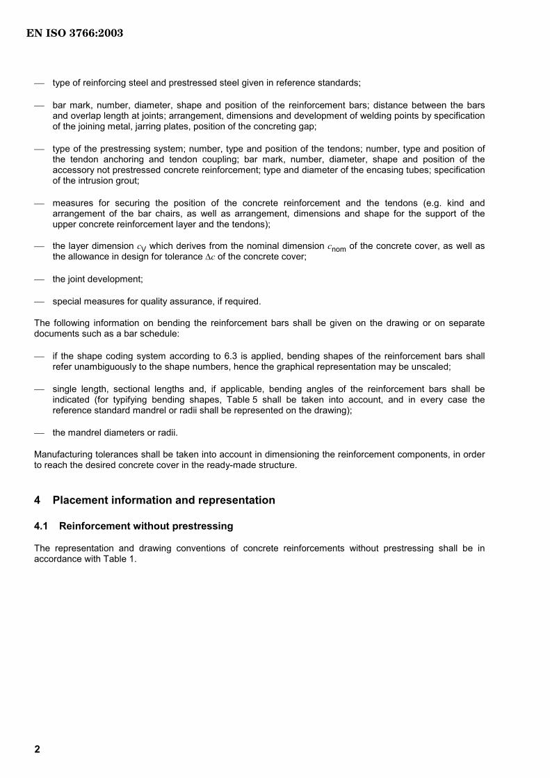
4 Placement information and representation
4.1 Reinforcement without prestressing
The representation and drawing conventions of concrete reinforcements without prestressing shall be in accordance with Table 1.
EN ISO 3766:2003
IS:6673 O3002(E)
I ©SO – 3002 All irthgs ersedevr 3
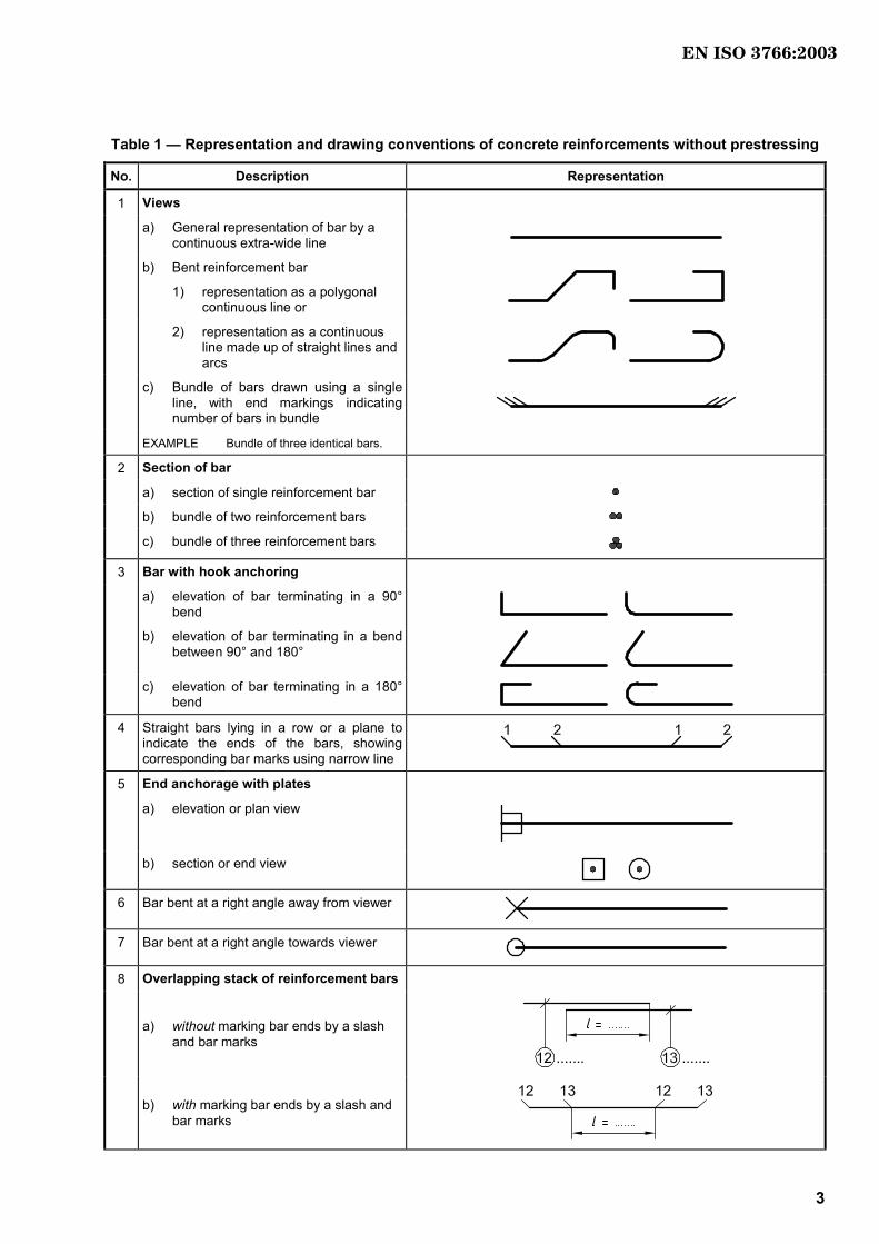
Table 1 — Representation and drawing conventions of concrete reinforcements without prestressing
No. Description Representation
1 Views
a) General representation of bar by a continuous extra-wide line
b) Bent reinforcement bar
1) representation as a polygonal continuous line or
2) representation as a continuous line made up of straight lines and arcs
c) Bundle of bars drawn using a single line, with end markings indicating number of bars in bundle
EXAMPLE Bundle of three identical bars.
2 Section of bar
a) section of single reinforcement bar b) bundle of two reinforcement bars
c) bundle of three reinforcement bars
3 Bar with hook anchoring
a) elevation of bar terminating in a 90° bend
b) elevation of bar terminating in a bend
between 90° and 180°
c) elevation of bar terminating in a 180° bend
4 Straight bars lying in a row or a plane to indicate the ends of the bars, showing corresponding bar marks using narrow line
5 End anchorage with plates
a) elevation or plan view
b) section or end view
6 Bar bent at a right angle away from viewer
7 Bar bent at a right angle towards viewer
8 Overlapping stack of reinforcement bars
a) without marking bar ends by a slash and bar marks
b) with marking bar ends by a slash and bar marks
EN ISO 3766:2003
IS:6673 O3002(E)
4 I ©SO – 3002 All irthgs ersedevr
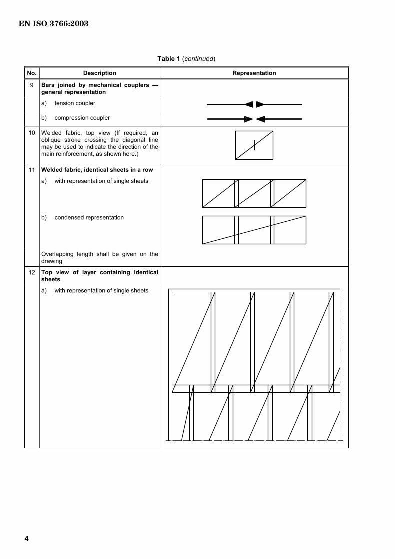
Table 1 (continued)
No. Description Representation
9 Bars joined by mechanical couplers — general representation
a) tension coupler
b) compression coupler
10 Welded fabric, top view (If required, an oblique stroke crossing the diagonal line may be used to indicate the direction of the main reinforcement, as shown here.)
11 Welded fabric, identical sheets in a row
a) with representation of single sheets
b) condensed representation
Overlapping length shall be given on the
drawing
12 Top view of layer containing identical sheets
a) with representation of single sheets
EN ISO 3766:2003

IS:6673 O3002(E)
I ©SO – 3002 All irthgs ersedevr 5
Table 1 (continued)
No. Description Representation
b) condensed representation with indication of overlapping
Overlapping length shall be given on the drawing
13 Welded fabric, section
a) simplified representation by a long dashed dotted extra-wide line
b) conventional representation
14 Set of identical bars
a) each set of identical bars indicated by one scaled-drawn reinforcement bar and a line terminated by oblique lines to mark extreme bars (circle connects “set line” with correct bar)
b) identical bars placed in groups.
15 Bars with a specification of the diameter or radius of mandrel, if differing from the minimum diameter or radius of the mandrel
NOTE A radius is indicated by the additional
letter R.
EN ISO 3766:2003

IS:6673 O3002(E)
6 I ©SO – 3002 All irthgs ersedevr
Table 1 (continued)
No. Description Representation
16 Location of layers of reinforcement on plan drawings
where
B is the bottom layer;
T is the top layer;
1 is the layer nearest the concrete face;
2 is the second layer from the concrete face.
NOTE B and T are used for the English language; equivalent letters for other languages are possible.
a) bottom and top layers shown on separate plans
b) bottom and top layers shown on the
same plan (The bottom layer shall be indicated by a dashed extra-wide line.)
17 Location of layers of reinforcement on
elevation drawings
where
N is the near face
F is the far face
1 is the layer nearest the concrete face
2 is the second layer from the concrete face
NOTE N and F are used for the English language; equivalent letters for other languages are possible.
a) near-face and far-face reinforcement shown on separate elevations
b) near-face and far-face reinforcement
shown on the same elevation (The far face layer shall be indicated by a dashed extra-wide line.)
EN ISO 3766:2003
IS:6673 O3002(E)
I ©SO – 3002 All irthgs ersedevr 7
Table 1 (continued)
No. Description Representation
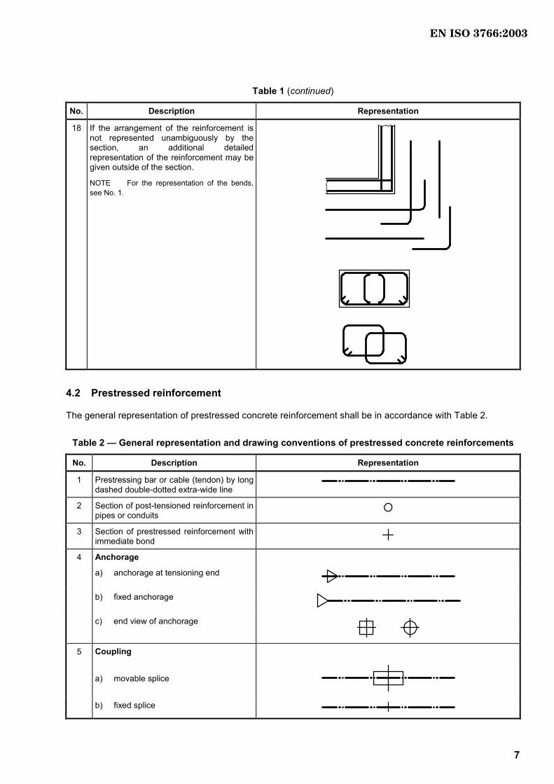
18 If the arrangement of the reinforcement is not represented unambiguously by the section, an additional detailed representation of the reinforcement may be given outside of the section.
NOTE For the representation of the bends, see No. 1.
4.2 Prestressed reinforcement
The general representation of prestressed concrete reinforcement shall be in accordance with Table 2.
Table 2 — General representation and drawing conventions of prestressed concrete reinforcements
No. Description Representation
1 Prestressing bar or cable (tendon) by long dashed double-dotted extra-wide line
2 Section of post-tensioned reinforcement in pipes or conduits
3 Section of prestressed reinforcement with immediate bond
4 Anchorage
a) anchorage at tensioning end
b) fixed anchorage
c) end view of anchorage
5 Coupling
a) movable splice
b) fixed splice
EN ISO 3766:2003

IS:6673 O3002(E)
8 I ©SO – 3002 All irthgs ersedevr
5 Marking
Items of information concerning reinforcing bars shall be written on the drawing in the longitudinal direction of the bars or along reference lines indicating the bars in question.
Items of information for welded fabric shall be written along the diagonal line. The sheet mark shall be indicated together with the number of sheets.
For every bar mark, details concerning reinforcement bars shall be given on the drawing in accordance with Table 3.
Table 3
Indication Example
Alphanumerical bar mark (surrounded by, for example, a circle or an oval)
a
Number of bars 19
Bar diameter, in millimetres Ø20
Spacing, in millimetres 200
Position in the component or construction part (optional) T
Shape code of reinforcement bar (optional) 13
a Indication for the example: 19 Ø20—200—T—13 or 19 Ø20—200. See Figure 1.
a) b)
NOTE The values in parentheses indicate the number of bars in the considered segment.
Figure 1 — Examples of bar markings (without options)
6 Bending information for unprestressed reinforcement bars
6.1 General
This clause specifies a system for the scheduling of reinforcing bars, and comprises
the method of indicating dimensions,
a coding system for bar shapes for optional use with a list of preferred bar shapes, and
information for the bar schedule (see Clause 7).
EN ISO 3766:2003

IS:6673 O3002(E)
I ©SO – 3002 All irthgs ersedevr 9
These specifications apply to all types of steel bars for the reinforcement of concrete. They do not apply to welded fabrics and prestressed steel reinforcement.
6.2 Indication of bar shapes
The bending dimensions shall be indicated as shown in Figures 2 to 8. None of the dimensions stated may be zero. The diameters and radii are inside dimensions, all other dimensions are outside dimensions. The mandrel radius or diameter is usually the smallest permissible diameter or radius according to reference standard regulations for the size of bar scheduled. These diameters or radii shall be stated on the drawing and on the bar schedule, if separate. When, in special cases, other diameters or radii are specified by reference standards, this shall be stated in the relevant documents of the bar schedule.
When the coding system of 6.3 is applied to an arc, the default case is assumed, with the exception of Shape codes 12, 13, 33, 67 and 77. In the case of the specification of bending angles, Shape code 99 shall be applied.
Figure 2 — Bending dimensions — Shape code 26
Figure 3 — Bending dimensions — Shape code 25
Figure 4 — Bending dimensions — Shape code 44
EN ISO 3766:2003

IS:6673 O3002(E)
10 I ©SO – 3002 All irthgs ersedevr
Figure 5 — Bending dimensions — Shape code 99 (non-standard example)
Figure 6 — Bending dimensions — Shape code 77
NOTE Rise of the arc b is optional.
Figure 7 — Bending dimensions — Shape code 67
EN ISO 3766:2003
IS:6673 O3002(E)
I ©SO – 3002 All irthgs ersedevr 11
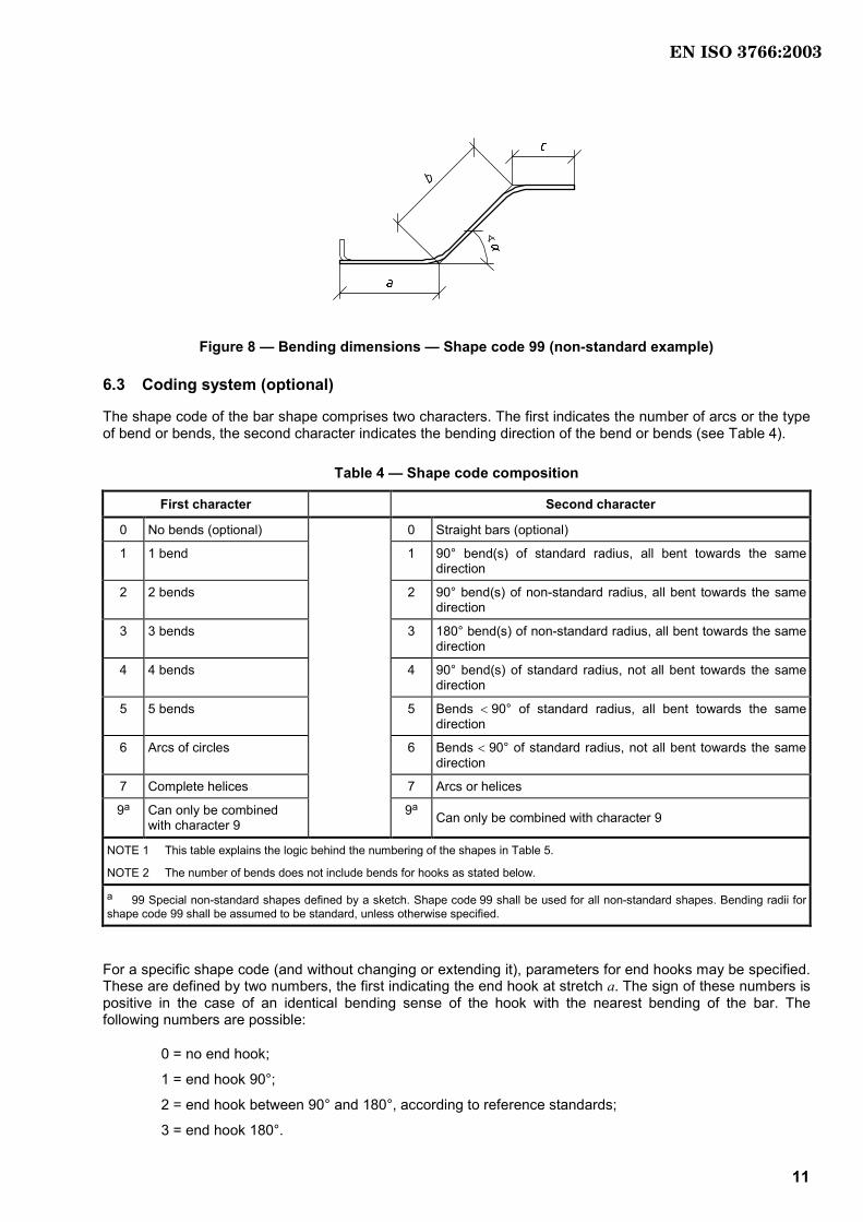
Figure 8 — Bending dimensions — Shape code 99 (non-standard example)
6.3 Coding system (optional)
The shape code of the bar shape comprises two characters. The first indicates the number of arcs or the type of bend or bends, the second character indicates the bending direction of the bend or bends (see Table 4).
Table 4 — Shape code composition
First character Second character
0 No bends (optional) 0 Straight bars (optional)
1 1 bend 1 90° bend(s) of standard radius, all bent towards the same direction
2 2 bends 2 90° bend(s) of non-standard radius, all bent towards the same direction
3 3 bends 3 180° bend(s) of non-standard radius, all bent towards the same direction
4 4 bends 4 90° bend(s) of standard radius, not all bent towards the same direction
5 5 bends 5 Bends < 90° of standard radius, all bent towards the same direction
6 Arcs of circles 6 Bends < 90° of standard radius, not all bent towards the same direction
7 Complete helices 7 Arcs or helices
9a Can only be combined with character 9
9a Can only be combined with character 9
NOTE 1 This table explains the logic behind the numbering of the shapes in Table 5.
NOTE 2 The number of bends does not include bends for hooks as stated below.
a 99 Special non-standard shapes defined by a sketch. Shape code 99 shall be used for all non-standard shapes. Bending radii for shape code 99 shall be assumed to be standard, unless otherwise specified.
For a specific shape code (and without changing or extending it), parameters for end hooks may be specified. These are defined by two numbers, the first indicating the end hook at stretch a. The sign of these numbers is positive in the case of an identical bending sense of the hook with the nearest bending of the bar. The following numbers are possible:
0 = no end hook;
1 = end hook 90°;
2 = end hook between 90° and 180°, according to reference standards;
3 = end hook 180°.
EN ISO 3766:2003

IS:6673 O3002(E)
12 I ©SO – 3002 All irthgs ersedevr
The lengths h and diameters or radii of the end hooks are given in reference standards and shall be indicated in the bar schedules.
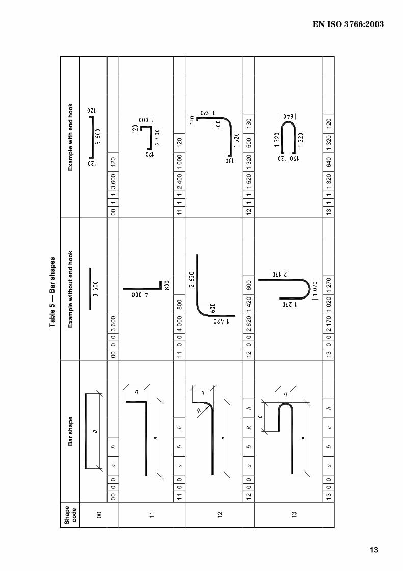
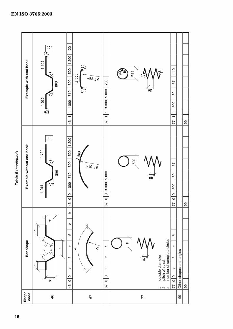
Preferred shapes for bars are given in Table 5. The dimension characters also relate to the corresponding columns of the shape schedule (see 7.2).
NOTE Run-out dimensions are not stated in Table 5.
EN ISO 3766:2003
IS:6673 O3002(E)
I ©SO – 3002 All irthgs ersedevr 13
Tabl
e 5
— B
ar s
hape
s
Shap
e co
de
Bar
sha
pe
Exam
ple
with
out e
nd h
ook
Exam
ple
with
end
hoo
k
00
00
0 0
a h
000
03
600
00
11
3 60
012
0
11
11
0 0
a b
h
110
04
000
800
111
12
400
1 00
012
0
12
12
0 0
a b
R h
120
02
620
1 42
060
0
121
11
520
1 32
050
0 13
0
13
13
0 0
a b
c h
130
02
170
1 02
01
270
13
11
1 32
064
0 1
320
120
EN ISO 3766:2003

IS:6673 O3002(E)
14 I ©SO – 3002 All irthgs ersedevr
Tabl
e 5
(con
tinue
d)
Shap
e co
de
Bar
sha
pe
Exam
ple
with
out e
nd h
ook
Exam
ple
with
end
hoo
k
15
15
0 0
a b
c h
150
01
000
4 80
01
500
15
1 1
1 00
04
800
1 50
012
0
21
21
0 0
a b
c h
210
03
000
1 00
080
0
21−1
−180
0 30
0 80
0 12
0
25
25
0 0
a b
c d
e h
250
030
0 2
000
500
200
100
25
2 2
800
1 00
080
0 74
0 77
5 15
0
26
26
0 0
a b
c d
h
260
01
000
1 20
01
400
1 18
5
26
11
700
700
1 20
050
0 12
0
EN ISO 3766:2003

IS:6673 O3002(E)
I ©SO – 3002 All irthgs ersedevr 15
Tabl
e 5
(con
tinue
d)
Shap
e co
de
Bar
sha
pe
Exam
ple
with
out e
nd h
ook
Exam
ple
with
end
hoo
k
31
31
0 0
a b
c d
h
310
080
0 55
0 40
0 45
0
31
01
800
550
400
450
100
(no
end
hook
s)
33
33
0 0
a b
c
330
01
200
500
2 90
0
41
41
0 0
a b
c d
e h
410
01
275
700
500
300
300
41
11
1 27
570
0 50
0 30
0 30
0 80
44
44
0 0
a b
c d
e h
440
010
0 30
0 20
0 70
0 10
0
441
120
0 45
0 30
0 45
0 20
0 80
EN ISO 3766:2003
IS:6673 O3002(E)
16 I ©SO – 3002 All irthgs ersedevr
Tabl
e 5
(con
tinue
d)
Shap
e co
de
Bar
sha
pe
Exam
ple
with
out e
nd h
ook
Exam
ple
with
end
hoo
k
46
46
0 0
a b
c d
e h
460
01
000
710
800
500
1 20
0
461
11
000
710
800
500
1 20
012
0
67
67
0 0
a R
h
670
03
000
5 00
0
67
11
3 00
05
000
200
a
outs
ide
diam
eter
b
pitc
h of
spi
ral
c nu
mbe
r of c
ompl
ete
circ
les
77
77
0 0
a b
c h
770
050
0 80
57
771
150
0 80
57
11
0
99
Oth
er s
hape
s an
d an
gles
99
99
99
EN ISO 3766:2003

IS:6673 O3002(E)
I ©SO – 3002 All irthgs ersedevr 17
7 Bar schedule
7.1 General
The bar schedule is the document used to specify and identify reinforcing bars. It is divided up into shape schedules (see 7.2) when applying shape codes, bending schedules (see 7.3) and combined schedules (see 7.4). Special mat schedules or weight schedules are also possible (see Annex A). Every schedule shall contain a title block containing elements in accordance with 7.5.
7.2 Shape schedule
A shape schedule shall contain the following information in the following sequence.
a) Member (identification of the structural member in which the bar is located).
b) Bar mark (unique reference of the bar).
c) Type of steel (designation or abbreviation given in reference standards or other rules). The bar's quality and profile can be designated by a single letter if it is properly defined.
EXAMPLE B is corresponding to FeB 500 (ribbed) given in EN 10080.
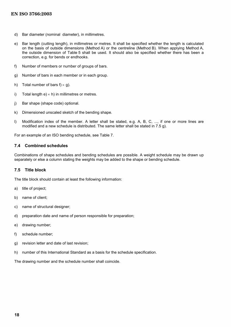
d) Bar diameter (nominal diameter), in millimetres.
e) Bar length (cutting length) in millimetres or metres. It shall be specified whether the length is calculated on the basis of outside dimensions (Method A) or the centreline (Method B). When Method A is applied, the outside dimensions of Table 5 shall be used. It should also be specified whether there has been a correction, e.g. for bends or endhooks.
f) Number of members or number of groups of bars.
g) Number of bars in each member or in each group.
h) Total number of bars f) × g).
i) Total length e) × h), in millimetres or metres.
j) Bar shape (shape code).
k) Definition of end hooks.
l) Bar-shape parameters (bending dimensions), in millimetres.
m) Modification index of the member. A letter shall be stated, e.g. A, B, C, ..., if one or more lines are modified and a new schedule is distributed. The same letter shall be stated in 7.5 g).
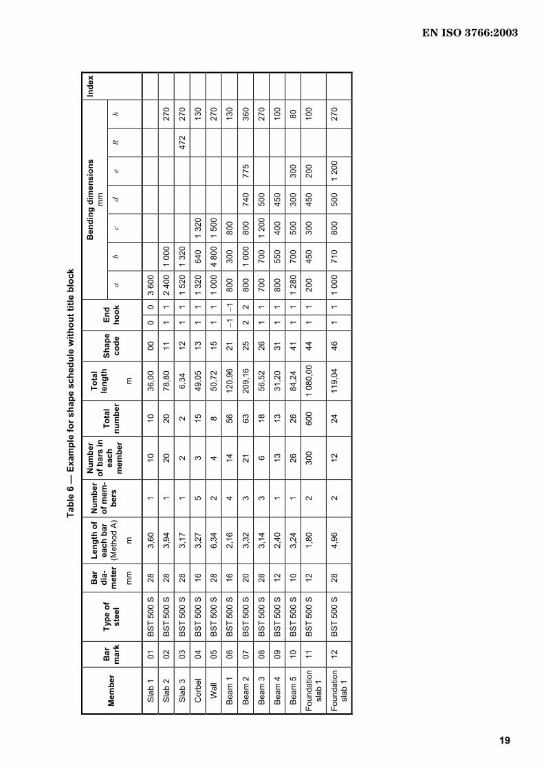
For an example of an ISO shape schedule, see Table 6.
7.3 Bending schedule
A bending schedule shall contain the following information in the sequence given.
a) Member (identification of the structural member in which the bar is located).
b) Bar mark (unique reference of the bar).
c) Type of steel (designation or abbreviation given in reference standards or other rules. The bar's quality and profile can be designated by a single letter if it is properly defined.
EN ISO 3766:2003
IS:6673 O3002(E)
18 I ©SO – 3002 All irthgs ersedevr
d) Bar diameter (nominal diameter), in millimetres.
e) Bar length (cutting length), in millimetres or metres. It shall be specified whether the length is calculated on the basis of outside dimensions (Method A) or the centreline (Method B). When applying Method A, the outside dimension of Table 5 shall be used. It should also be specified whether there has been a correction, e.g. for bends or endhooks.
f) Number of members or number of groups of bars.
g) Number of bars in each member or in each group.
h) Total number of bars f) × g).
i) Total length e) × h) in millimetres or metres.
j) Bar shape (shape code) optional.
k) Dimensioned unscaled sketch of the bending shape.
l) Modification index of the member. A letter shall be stated, e.g. A, B, C, ..., if one or more lines are modified and a new schedule is distributed. The same letter shall be stated in 7.5 g).
For an example of an ISO bending schedule, see Table 7.
7.4 Combined schedules
Combinations of shape schedules and bending schedules are possible. A weight schedule may be drawn up separately or else a column stating the weights may be added to the shape or bending schedule.
7.5 Title block
The title block should contain at least the following information:
a) title of project;
b) name of client;
c) name of structural designer;
d) preparation date and name of person responsible for preparation;
e) drawing number;
f) schedule number;
g) revision letter and date of last revision;
h) number of this International Standard as a basis for the schedule specification.
The drawing number and the schedule number shall coincide.
EN ISO 3766:2003
IS:6673 O3002(E)
I ©SO – 3002 All irthgs ersedevr 19
Tabl
e 6
— E
xam
ple
for s
hape
sch
edul
e w
ithou
t titl
e bl
ock
Ben
ding
dim
ensi
ons
mm
In
dex
Mem
ber
Bar
m
ark
Type
of
stee
l
Bar
di
a-m
eter
mm
Leng
th o
f ea
ch b
ar(M
etho
d A)
m
Num
ber
of m
em-
bers
Num
ber
of b
ars
in
each
m
embe
r
Tota
l nu
mbe
r
Tota
l le
ngth m
Shap
e co
de
End
hook
a
b c
d e
R h
Slab
1
01
BST
500
S 28
3,
60
1 10
10
36
,00
00
0 0
3 60
0
Slab
2
02
BST
500
S 28
3,
94
1 20
20
78
,80
11
1 1
2 40
01
000
270
Slab
3
03
BST
500
S 28
3,
17
1 2
2 6,
34
12
1 1
1 52
01
320
47
2 27
0
Cor
bel
04
BST
500
S 16
3,
27
5 3
15
49,0
5 13
1
1 1
320
640
1 32
0
130
Wal
l 05
BS
T 50
0 S
28
6,34
2
4 8
50,7
2 15
1
1 1
000
4 80
01
500
27
0
Beam
1
06
BST
500
S 16
2,
16
4 14
56
12
0,96
21
−1
−1
800
300
800
13
0
Beam
2
07
BST
500
S 20
3,
32
3 21
63
20
9,16
25
2
2 80
0 1
000
800
740
775
36
0
Beam
3
08
BST
500
S 28
3,
14
3 6
18
56,5
2 26
1
1 70
0 70
0 1
200
500
270
Beam
4
09
BST
500
S 12
2,
40
1 13
13
31
,20
31
1 1
800
550
400
450
100
Beam
5
10
BST
500
S 10
3,
24
1 26
26
84
,24
41
1 1
1 28
070
0 50
0 30
0 30
0
80
Foun
datio
n sl
ab 1
11
BS
T 50
0 S
12
1,80
2
300
600
1 08
0,00
44
1 1
200
450
300
450
200
10
0
Foun
datio
n sl
ab 1
12
BS
T 50
0 S
28
4,96
2
12
24
119,
04
46
1 1
1 00
071
0 80
0 50
0 1
200
27
0
EN ISO 3766:2003

IS:6673 O3002(E)
20 I ©SO – 3002 All irthgs ersedevr
Tabl
e 7
— E
xam
ple
for b
endi
ng s
ched
ule
with
out t
itle
bloc
k
Mem
ber
Bar
m
ark
Type
of
stee
l
Bar
di
amet
er
mm
Leng
th o
f ea
ch b
ar(M
etho
d A)
m
Num
ber
of
mem
bers
Num
ber
of b
ars
in
each
m
embe
r
Tota
l nu
mbe
rTo
tal
leng
th
m
Shap
e co
de
(Opt
iona
l)B
endi
ng s
hape
with
dim
ensi
ons
Inde
x
Slab
1
01
BST
500
S 28
3,
60
1 10
10
36
,00
00
Slab
2
02
BST
500
S 28
3,
94
1 20
20
78
,80
11
Cor
bel
04
BST
500
S 16
3,
27
5 3
15
49,0
5 13
Wal
l 05
BS
T 50
0 S
28
6,34
2
4 8
50,7
2 15
Beam
1
06
BST
500
S 16
2,
16
4 14
56
12
0,96
21
Floo
r sla
b 14
BS
T 50
0 S
20
1,80
1
300
300
540,
00
NO
TE
3D re
pres
enta
tion.
Supp
ort p
illar
17
BST
500
S 10
2,
26
5 19
95
21
4,70
EN ISO 3766:2003

IS:6673 O3002(E)
I ©SO – 3002 All irthgs ersedevr 21
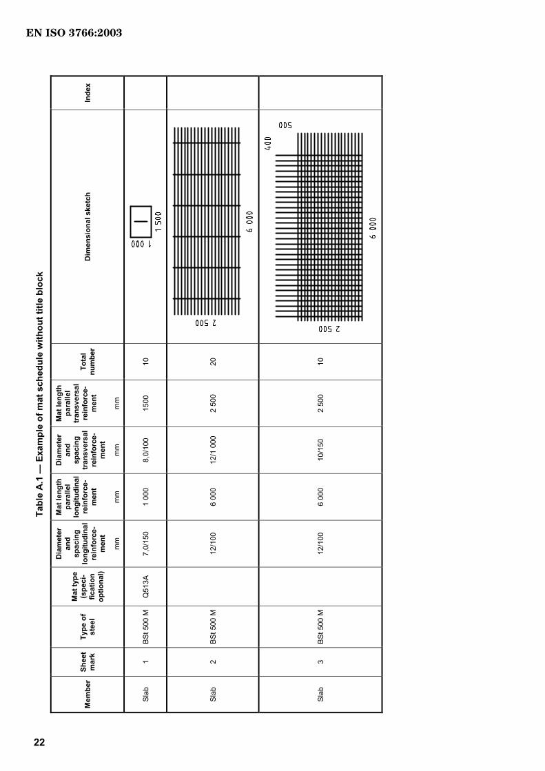
Annex A (informative)
Mat schedule — Example
EN ISO 3766:2003
IS:6673 O3002(E)
22 I ©SO – 3002 All irthgs ersedevr
Tabl
e A.
1 —
Exa
mpl
e of
mat
sch
edul
e w
ithou
t titl
e bl
ock
Mem
ber
Shee
t m
ark
Type
of
stee
l
Mat
type
(s
peci
-fic
atio
n op
tiona
l)
Dia
met
er
and
spac
ing
long
itudi
nal
rein
forc
e-m
ent
mm
Mat
leng
th
para
llel
long
itudi
nal
rein
forc
e-m
ent
mm
Dia
met
er
and
spac
ing
tran
sver
sal
rein
forc
e-m
ent
mm
Mat
leng
th
para
llel
tran
sver
sal
rein
forc
e-m
ent
mm
Tota
l nu
mbe
r D
imen
sion
al s
ketc
h In
dex
Slab
1
BSt 5
00 M
Q
513A
7,
0/15
0 1
000
8,0/
100
1500
10
Slab
2
BSt 5
00 M
12/1
00
6 00
0 12
/1 0
00
2 50
0 20
Slab
3
BSt 5
00 M
12/1
00
6 00
0 10
/150
2
500
10
EN ISO 3766:2003

blank
BS EN ISO 3766:2003
BSI
389 Chiswick High Road
London
W4 4AL
BSI — British Standards InstitutionBSI is the independent national body responsible for preparing British Standards. It presents the UK view on standards in Europe and at the international level. It is incorporated by Royal Charter.
Revisions
British Standards are updated by amendment or revision. Users of British Standards should make sure that they possess the latest amendments or editions.
It is the constant aim of BSI to improve the quality of our products and services. We would be grateful if anyone finding an inaccuracy or ambiguity while using this British Standard would inform the Secretary of the technical committee responsible, the identity of which can be found on the inside front cover. Tel: +44 (0)20 8996 9000. Fax: +44 (0)20 8996 7400.
BSI offers members an individual updating service called PLUS which ensures that subscribers automatically receive the latest editions of standards.
Buying standards
Orders for all BSI, international and foreign standards publications should be addressed to Customer Services. Tel: +44 (0)20 8996 9001. Fax: +44 (0)20 8996 7001. Email: [email protected]. Standards are also available from the BSI website at http://www.bsi-global.com.
In response to orders for international standards, it is BSI policy to supply the BSI implementation of those that have been published as British Standards, unless otherwise requested.
Information on standards
BSI provides a wide range of information on national, European and international standards through its Library and its Technical Help to Exporters Service. Various BSI electronic information services are also available which give details on all its products and services. Contact the Information Centre. Tel: +44 (0)20 8996 7111. Fax: +44 (0)20 8996 7048. Email: [email protected].
Subscribing members of BSI are kept up to date with standards developments and receive substantial discounts on the purchase price of standards. For details of these and other benefits contact Membership Administration. Tel: +44 (0)20 8996 7002. Fax: +44 (0)20 8996 7001. Email: [email protected].
Information regarding online access to British Standards via British Standards Online can be found at http://www.bsi-global.com/bsonline.
Further information about BSI is available on the BSI website at http://www.bsi-global.com.
Copyright
Copyright subsists in all BSI publications. BSI also holds the copyright, in the UK, of the publications of the international standardization bodies. Except as permitted under the Copyright, Designs and Patents Act 1988 no extract may be reproduced, stored in a retrieval system or transmitted in any form or by any means – electronic, photocopying, recording or otherwise – without prior written permission from BSI.
This does not preclude the free use, in the course of implementing the standard, of necessary details such as symbols, and size, type or grade designations. If these details are to be used for any other purpose than implementation then the prior written permission of BSI must be obtained.
Details and advice can be obtained from the Copyright & Licensing Manager. Tel: +44 (0)20 8996 7070. Fax: +44 (0)20 8996 7553. Email: [email protected].