SHIPPING DEPUTY MINISTRY
78
REPUBLIC OF CYPRUS SHIPPING DEPUTY MINISTRY Kyllinis Street, Mesa Geitonia, 4007 Lemesos, Postal Address: P.O.Box 56193, 3305 Lemesos, Cyprus Telephone: +357 25848100, Telefax: +357 25848200 E-mail: [email protected], Web page: http://www.shipping.gov.cy Circular No. 17/2021 13 April 2021 SDM 5.13.09 SDM 16.17.10 To: Registered Owners, Registered bareboat charterers, Managers and Representatives of Ships under the Cyprus flag To all Recognised Organisations (ROs), Subject: Technical Standards for certain categories of vessels issued under the Government Policy on the Registration of Vessels in the Cyprus Register of Ships 1. The Shipping Deputy Ministry (SDM) establishes technical requirements for certain categories of vessels with respect to their registration in the Registry of Cyprus Ships, through the Technical Standards attached to this Circular. The purpose of the Standards is to specify technical requirements on areas not currently covered by National, European Union, or International Legislation, as well as to inform parties interested in the registration of vessels to whom the Standards apply in the Registry of Cyprus ships, of the available options offered by the SDM. 2. Τhese Technical Standards have been determined by the Shipping Deputy Minister to the President as part of the Government Policy on the Registration of Vessels in the Cyprus Register of Ships pursuant to the provisions of section 14B of the Merchant Shipping (Registration of Ships, Sales and Mortgages) Laws of 1963-2020 (Law 45/1963 as amended). Thus, this Circular is supplementary to the relevant Circular currently in force, i.e Circular No. 10/2019, and any future Circular amending and/or replacing Circular No. 10/2019. 3. In particular, and in accordance with the categorization established within the Standards, these are applicable to the following categories of vessels: Category A - Cargo ships of more than 24 metres in load line length and below 500GT. Category B - Motor or sailing vessels used for pleasure and engaged in trade, of more than 24 metres in load line length and below 500GT carrying up to 12 passengers. Sail training vessels are also included in this category.
Transcript of SHIPPING DEPUTY MINISTRY

REPUBLIC OF CYPRUS
SHIPPING DEPUTY MINISTRY
Kyllinis Street, Mesa Geitonia, 4007 Lemesos, Postal Address: P.O.Box 56193, 3305 Lemesos, Cyprus Telephone: +357 25848100, Telefax: +357 25848200
E-mail: [email protected], Web page: http://www.shipping.gov.cy
Circular No. 17/2021 13 April 2021 SDM 5.13.09 SDM 16.17.10 To: Registered Owners, Registered bareboat charterers, Managers and Representatives of Ships under the Cyprus flag To all Recognised Organisations (ROs),
Subject: Technical Standards for certain categories of vessels issued under the Government Policy on the Registration of Vessels in the Cyprus Register of Ships
1. The Shipping Deputy Ministry (SDM) establishes technical requirements for certain categories of vessels with respect to their registration in the Registry of Cyprus Ships, through the Technical Standards attached to this Circular. The purpose of the Standards is to specify technical requirements on areas not currently covered by National, European Union, or International Legislation, as well as to inform parties interested in the registration of vessels to whom the Standards apply in the Registry of Cyprus ships, of the available options offered by the SDM. 2. Τhese Technical Standards have been determined by the Shipping Deputy Minister to the President as part of the Government Policy on the Registration of Vessels in the Cyprus Register of Ships pursuant to the provisions of section 14B of the Merchant Shipping (Registration of Ships, Sales and Mortgages) Laws of 1963-2020 (Law 45/1963 as amended). Thus, this Circular is supplementary to the relevant Circular currently in force, i.e Circular No. 10/2019, and any future Circular amending and/or replacing Circular No. 10/2019. 3. In particular, and in accordance with the categorization established within the Standards, these are applicable to the following categories of vessels:
Category A - Cargo ships of more than 24 metres in load line length and below 500GT.
Category B - Motor or sailing vessels used for pleasure and engaged in trade, of more than 24 metres in load line length and below 500GT carrying up to 12 passengers. Sail training vessels are also included in this category.
2
Category C - Motor or sailing vessels of more than 24 metres in load line length and below 500GT carrying up to 12 passengers, which at the time, are considered to be pleasure vessels not engaged in trade.
Category D - Vessels used for pleasure and engaged in trade carrying from 13 up to 36 passengers.
In particular it is highlighted that the said technical Standards apply to Yachts and Mega Yachts. 4. The said Technical Standards will apply as from the 15th of April 2021. In essence, the Standards will apply to vessels for which the application for their registration in the Registry of Cyprus ships, will be made on or after the 15th of April 2021. Any queries in relation to the Technical Standards should be addressed to the following email address: [email protected].
Neophytos Papadopoulos
Registrar of Cyprus Ships,
Permanent Secretary,
Shipping Deputy Ministry
Cc: - Permanent Secretary, Ministry of Foreign Affairs - Maritime Offices of the Shipping Deputy Ministry abroad - Diplomatic and Consular Missions of the Republic - Honorary Consular Officers of the Republic - Cyprus Shipping Chamber - Cyprus Union of Shipowners - Cyprus Bar Association
1
Cyprus Vessels Technical Standards
Τεχνικά Πρότυπα Κυπριακών Σκαφών
Applicable to:
1. vessels of more than 24 meters in load line length and below 500
GT which:
[a] are in commercial operation as cargo ships (Category A)or
[b] vessels used for pleasure and engaged in trade, carrying up
to 12 passengers(category B), or
[c] pleasure vessels not engaged in trade carrying up to 12
passengers (category C)
2. Vessels used for pleasure and engaged in trade, carrying from 13
up to 36 passengers (category D).
v 06 April 2021
2
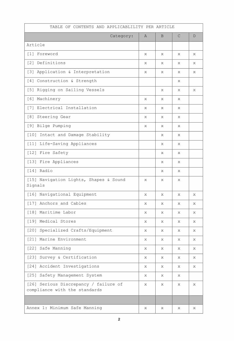
TABLE OF CONTENTS AND APPLICABLILITY PER ARTICLE
Category: A B C D
Article
[1] Foreword x x x x
[2] Definitions x x x x
[3] Application & Interpretation x x x x
[4] Construction & Strength x
[5] Rigging on Sailing Vessels x x x
[6] Machinery x x x
[7] Electrical Installation x x x
[8] Steering Gear x x x
[9] Bilge Pumping x x x
[10] Intact and Damage Stability x x
[11] Life-Saving Appliances x x
[12] Fire Safety x x
[13] Fire Appliances x x
[14] Radio x x
[15] Navigation Lights, Shapes & Sound
Signals
x x x
[16] Navigational Equipment x x x x
[17] Anchors and Cables x x x x
[18] Maritime Labor x x x x
[19] Medical Stores x x x x
[20] Specialized Crafts/Equipment x x x x
[21] Marine Environment x x x x
[22] Safe Manning x x x x
[23] Survey & Certification x x x x
[24] Accident Investigations x x x x
[25] Safety Management System x x x
[26] Serious Discrepancy / failure of
compliance with the standards
x x x x
Annex 1: Minimum Safe Manning x x x x
3
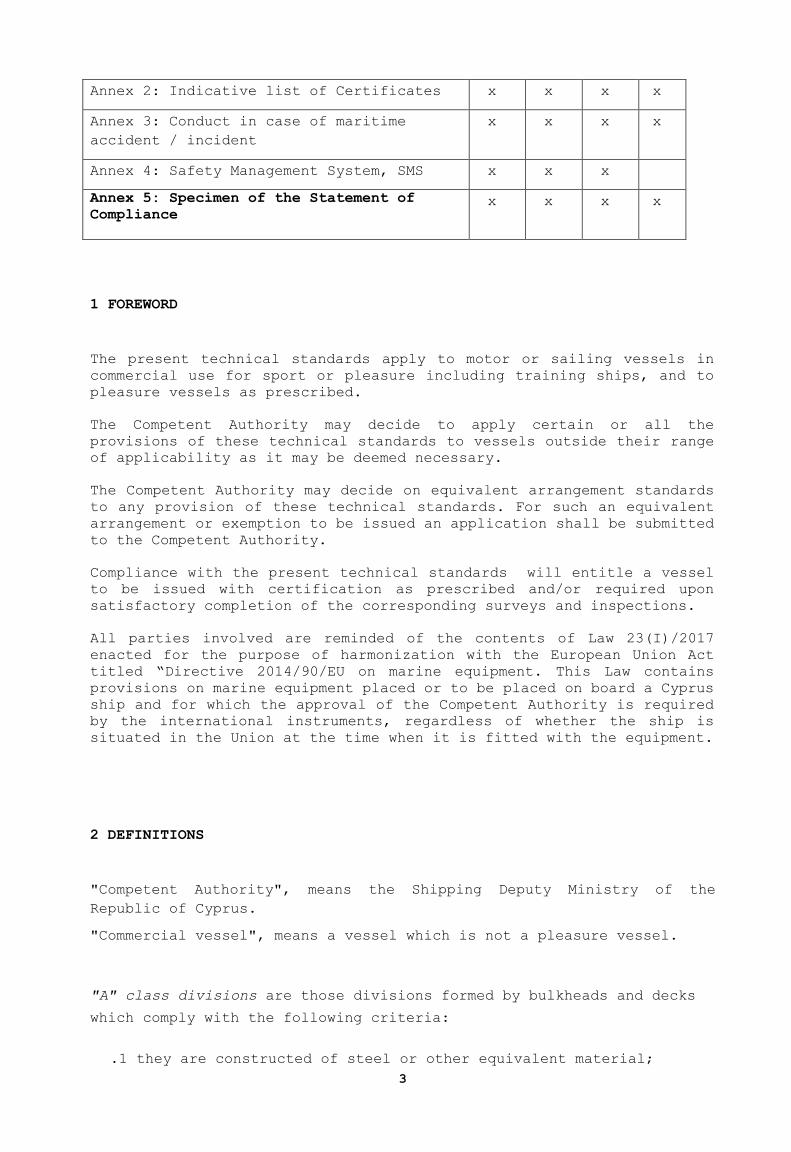
Annex 2: Indicative list of Certificates x x x x
Annex 3: Conduct in case of maritime
accident / incident
x x x x
Annex 4: Safety Management System, SMS x x x
Annex 5: Specimen of the Statement of
Compliance x x x x
1 FOREWORD
The present technical standards apply to motor or sailing vessels in
commercial use for sport or pleasure including training ships, and to
pleasure vessels as prescribed.
The Competent Authority may decide to apply certain or all the
provisions of these technical standards to vessels outside their range
of applicability as it may be deemed necessary.
The Competent Authority may decide on equivalent arrangement standards
to any provision of these technical standards. For such an equivalent
arrangement or exemption to be issued an application shall be submitted
to the Competent Authority.
Compliance with the present technical standards will entitle a vessel
to be issued with certification as prescribed and/or required upon
satisfactory completion of the corresponding surveys and inspections.
All parties involved are reminded of the contents of Law 23(I)/2017
enacted for the purpose of harmonization with the European Union Act
titled “Directive 2014/90/EU on marine equipment. This Law contains
provisions on marine equipment placed or to be placed on board a Cyprus
ship and for which the approval of the Competent Authority is required
by the international instruments, regardless of whether the ship is
situated in the Union at the time when it is fitted with the equipment.
2 DEFINITIONS
"Competent Authority", means the Shipping Deputy Ministry of the
Republic of Cyprus.
"Commercial vessel", means a vessel which is not a pleasure vessel.
"A" class divisions are those divisions formed by bulkheads and decks
which comply with the following criteria:
.1 they are constructed of steel or other equivalent material;

4
.2 they are suitably stiffened;
.3 they are insulated with approved non-combustible materials such
that the average temperature of the unexposed side will not rise more
than 140 degrees C above the original temperature, nor will the
temperature, at any one point, including any joint, rise more than
180 degrees C above the original temperature, within the time listed
below:
class "A-60" 60 min
class "A-30" 30 min
class "A-15" 15 min
class "A-0" 0 min
"B" class divisions are those divisions formed by bulkheads, decks,
ceilings or linings which comply with the following criteria:
.1 they are constructed of approved non-combustible materials and all
materials used in the construction and erection of "B" class
divisions are non-combustible, with the exception that combustible
veneers may be permitted provided they meet other appropriate
requirements of this chapter;
.2 they have an insulation value such that the average temperature of
the unexposed side will not rise more than 140 degrees C above the
original temperature, nor will the temperature at any one point,
including any joint, rise more than 225 degrees C above the original
temperature, within the time listed below:
class "B-15" 15 min
class "B-0" 0 min
.3 they are constructed as to be capable of preventing the passage of
flame to the end of the first half hour of the standard fire test;
and
.4 the Competent Authority has required a test of a prototype division
in accordance with the Fire Test Procedures Code to ensure that it
meets the above requirements for integrity and temperature rise.
"Existing vessel" means any vessel, the keel of which was laid or was
at a similar stage of construction prior to the date of entry into
force of these technical standards.
5
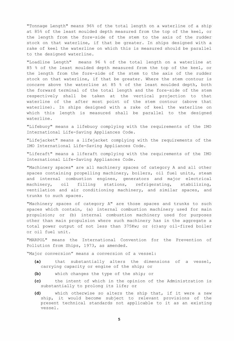
"Tonnage Length" means 96% of the total length on a waterline of a ship
at 85% of the least moulded depth measured from the top of the keel, or
the length from the fore-side of the stem to the axis of the rudder
stock on that waterline, if that be greater. In ships designed with a
rake of keel the waterline on which this is measured should be parallel
to the designed waterline.
"Loadline Length" means 96 % of the total length on a waterline at
85 % of the least moulded depth measured from the top of the keel, or
the length from the fore-side of the stem to the axis of the rudder
stock on that waterline, if that be greater. Where the stem contour is
concave above the waterline at 85 % of the least moulded depth, both
the forward terminal of the total length and the fore-side of the stem
respectively shall be taken at the vertical projection to that
waterline of the after most point of the stem contour (above that
waterline). In ships designed with a rake of keel the waterline on
which this length is measured shall be parallel to the designed
waterline.
"Lifebuoy" means a lifebuoy complying with the requirements of the IMO
International Life-Saving Appliances Code.
"Lifejacket" means a lifejacket complying with the requirements of the
IMO International Life-Saving Appliances Code.
"Liferaft" means a liferaft complying with the requirements of the IMO
International Life-Saving Appliances Code.
"Machinery spaces" are all machinery spaces of category A and all other
spaces containing propelling machinery, boilers, oil fuel units, steam
and internal combustion engines, generators and major electrical
machinery, oil filling stations, refrigerating, stabilizing,
ventilation and air conditioning machinery, and similar spaces, and
trunks to such spaces.
"Machinery spaces of category A" are those spaces and trunks to such
spaces which contain, (a) internal combustion machinery used for main
propulsion; or (b) internal combustion machinery used for purposes
other than main propulsion where such machinery has in the aggregate a
total power output of not less than 375Kw; or (c)any oil-fired boiler
or oil fuel unit.
"MARPOL" means the International Convention for the Prevention of
Pollution from Ships, 1973, as amended.
“Major conversion” means a conversion of a vessel:
(a) that substantially alters the dimensions of a vessel,
carrying capacity or engine of the ship; or
(b) which changes the type of the ship; or
(c) the intent of which in the opinion of the Administration is
substantially to prolong its life; or
(d) which otherwise so alters the ship that, if it were a new
ship, it would become subject to relevant provisions of the
present technical standards not applicable to it as an existing
vessel.
6
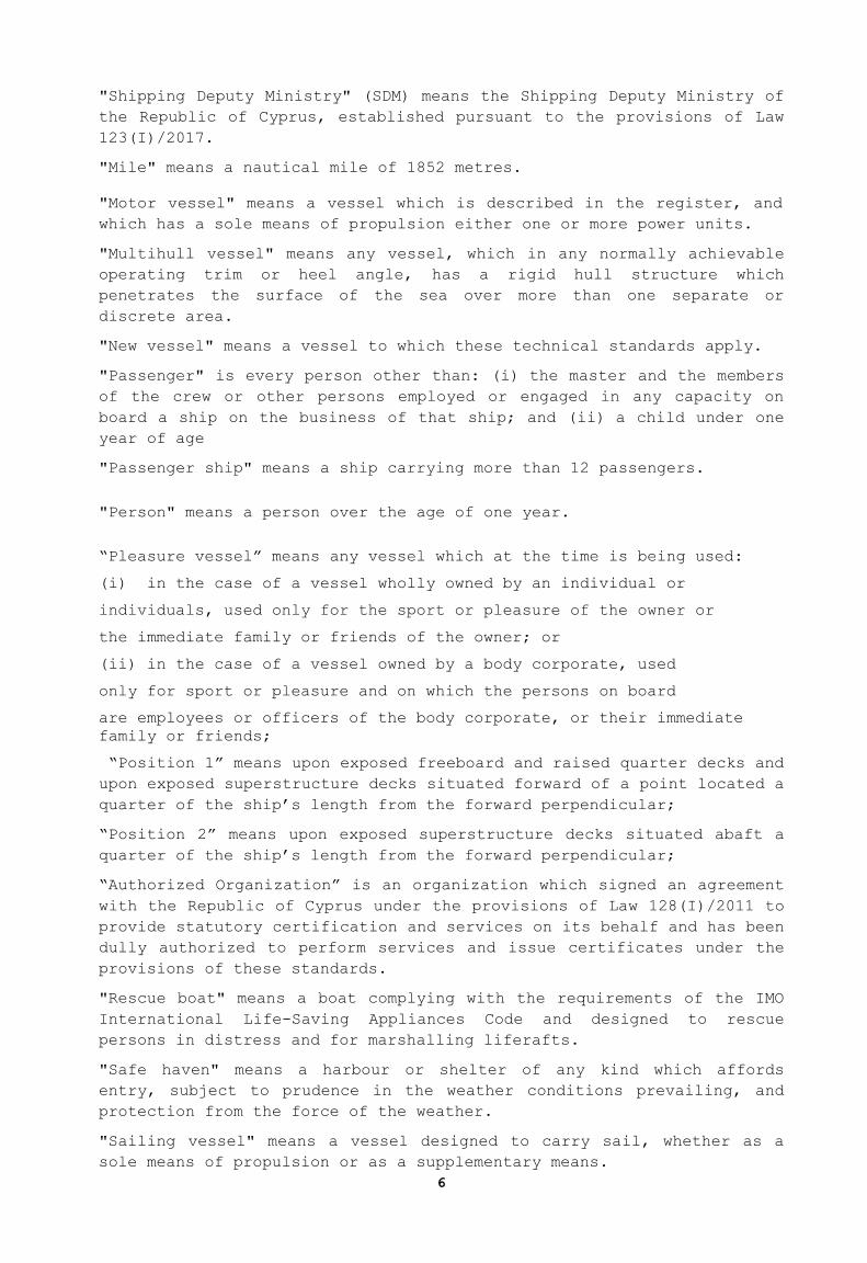
"Shipping Deputy Ministry" (SDM) means the Shipping Deputy Ministry of
the Republic of Cyprus, established pursuant to the provisions of Law
123(I)/2017.
"Mile" means a nautical mile of 1852 metres.
"Motor vessel" means a vessel which is described in the register, and
which has a sole means of propulsion either one or more power units.
"Multihull vessel" means any vessel, which in any normally achievable
operating trim or heel angle, has a rigid hull structure which
penetrates the surface of the sea over more than one separate or
discrete area.
"New vessel" means a vessel to which these technical standards apply.
"Passenger" is every person other than: (i) the master and the members
of the crew or other persons employed or engaged in any capacity on
board a ship on the business of that ship; and (ii) a child under one
year of age
"Passenger ship" means a ship carrying more than 12 passengers.
"Person" means a person over the age of one year.
“Pleasure vessel” means any vessel which at the time is being used:
(i) in the case of a vessel wholly owned by an individual or
individuals, used only for the sport or pleasure of the owner or
the immediate family or friends of the owner; or
(ii) in the case of a vessel owned by a body corporate, used
only for sport or pleasure and on which the persons on board
are employees or officers of the body corporate, or their immediate
family or friends;
“Position 1” means upon exposed freeboard and raised quarter decks and
upon exposed superstructure decks situated forward of a point located a
quarter of the ship’s length from the forward perpendicular;
“Position 2” means upon exposed superstructure decks situated abaft a
quarter of the ship’s length from the forward perpendicular;
“Authorized Organization” is an organization which signed an agreement
with the Republic of Cyprus under the provisions of Law 128(I)/2011 to
provide statutory certification and services on its behalf and has been
dully authorized to perform services and issue certificates under the
provisions of these standards.
"Rescue boat" means a boat complying with the requirements of the IMO
International Life-Saving Appliances Code and designed to rescue
persons in distress and for marshalling liferafts.
"Safe haven" means a harbour or shelter of any kind which affords
entry, subject to prudence in the weather conditions prevailing, and
protection from the force of the weather.
"Sailing vessel" means a vessel designed to carry sail, whether as a
sole means of propulsion or as a supplementary means.

7
"Sail training vessel" means a sailing vessel which, at the time, is
being used either (a) to provide instruction in the principles of
responsibility, management and to advance education in the art of
seamanship; or (b) to provide instruction in navigation and seamanship;
"Short Range Vessel" means a vessel which is:
[1] restricted to operating in forecast or actual wind of a maximum
Beaufort Force 4, for a motor vessel, and Beaufort Force 6 for a
sailing vessel; or
[2] operates within 60 nautical miles of a safe haven. (The
Administration may permit operation on specified routes up to 90
nautical miles from a safe haven as appropriate)or
[3] any other operational restrictions specified by the Administration
as appropriate.
“Similar stage of construction” means at a stage which (a) construction
identifiable with a specific vessel begins; or (b) assembly of that
vessel, comprising at least 1% of the estimated mass of all structural
material has commenced; or (c) the Administration was notified about
its construction and vessel under construction was surveyed by the
Administration and issued a statement of stage of construction.
In the case of vessels constructed of FRP or GRP, this will be
considered as the date when more than 5% of the hull resin and
reinforcement has been laid.
”SOLAS" means the International Convention of Safety of Life at Sea,
1974, as amended.
"Submersible Craft" means any description of manned mobile submersible
apparatus which is designed to maintain some or all of its occupants
at or near atmospheric pressure including free, self-propelled,
tethered, towed or bottom contact propelled apparatus and atmospheric
diving suits.
A diving bell is not a submersible craft for the purposes of these
technical standards; and "diving bell" means any compression chamber
which is capable of being manned and is used or designed for use under
the surface of water in supporting human life being a chamber in which
any occupant is or may be subjected to a pressure of more than 300
millibars above the ambient pressure during normal operation;
"Survival craft" means a craft capable of sustaining the lives of
persons in distress from the time of abandoning the ship.
"Training Ship" Training Ship which may be either a sailing or motor
vessel, means a vessel which is operated to provide instruction in the
principles of responsibility, resourcefulness, team management; and/or
provide instruction in navigation and seamanship, marine engineering
or other shipboard related skills. A training ship may carry a
combination of passengers and trainees but their total number should
not exceed 12.
"Watertight" means capable of preventing the passage of water in any
direction.
8
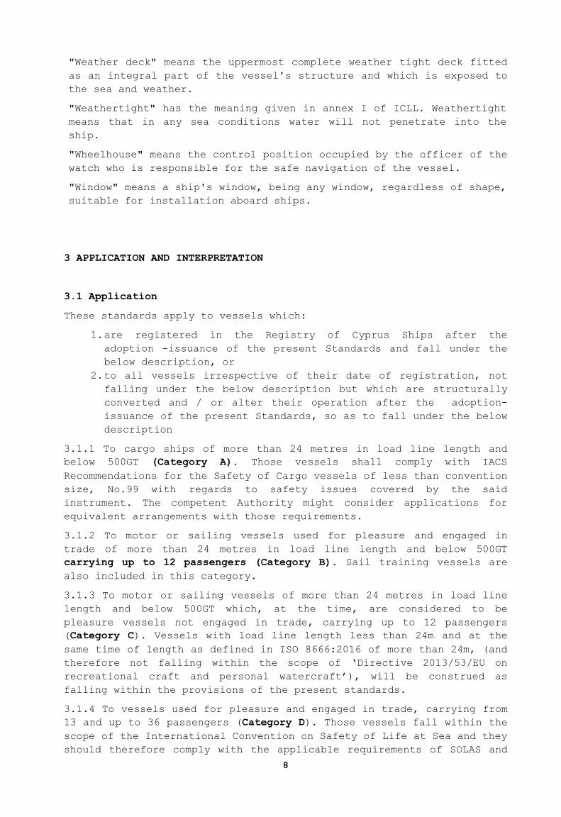
"Weather deck" means the uppermost complete weather tight deck fitted
as an integral part of the vessel's structure and which is exposed to
the sea and weather.
"Weathertight" has the meaning given in annex I of ICLL. Weathertight
means that in any sea conditions water will not penetrate into the
ship.
"Wheelhouse" means the control position occupied by the officer of the
watch who is responsible for the safe navigation of the vessel.
"Window" means a ship's window, being any window, regardless of shape,
suitable for installation aboard ships.
3 APPLICATION AND INTERPRETATION
3.1 Application
These standards apply to vessels which:
1. are registered in the Registry of Cyprus Ships after the
adoption -issuance of the present Standards and fall under the
below description, or
2. to all vessels irrespective of their date of registration, not
falling under the below description but which are structurally
converted and / or alter their operation after the adoption-
issuance of the present Standards, so as to fall under the below
description
3.1.1 To cargo ships of more than 24 metres in load line length and
below 500GT (Category A). Those vessels shall comply with IACS
Recommendations for the Safety of Cargo vessels of less than convention
size, No.99 with regards to safety issues covered by the said
instrument. The competent Authority might consider applications for
equivalent arrangements with those requirements.
3.1.2 To motor or sailing vessels used for pleasure and engaged in
trade of more than 24 metres in load line length and below 500GT
carrying up to 12 passengers (Category B). Sail training vessels are
also included in this category.
3.1.3 To motor or sailing vessels of more than 24 metres in load line
length and below 500GT which, at the time, are considered to be
pleasure vessels not engaged in trade, carrying up to 12 passengers
(Category C). Vessels with load line length less than 24m and at the
same time of length as defined in ISO 8666:2016 of more than 24m, (and
therefore not falling within the scope of ‘Directive 2013/53/EU on
recreational craft and personal watercraft’), will be construed as
falling within the provisions of the present standards.
3.1.4 To vessels used for pleasure and engaged in trade, carrying from
13 and up to 36 passengers (Category D). Those vessels fall within the
scope of the International Convention on Safety of Life at Sea and they
should therefore comply with the applicable requirements of SOLAS and
9
any other International Conventions as the case may be. The Competent
Authority however, might on a case-by-case basis and upon application
by the owner, examine and approve equivalent arrangements based on
vessels’ compliance with equivalent regulations established by other
Administrations, which have been notified to IMO. The approved
equivalences and any conditions thereof will be included in the
vessels’ Statement of Compliance.
3.1.5 Vessels undergoing refit or modification are encouraged to comply
with the provisions of these technical standards as far as is
reasonable and practicable.
3.1.6 The Administration may decide to apply certain or all the
provisions of these technical standards to vessels outside the range of
their applicability as it may be deemed necessary.
3.1.7 The present technical standards do not apply to:
- Fishing vessels
- Governmental vessels not engaged in commercial activities
- Historical Ships or Wooden Ships of primitive built
3.2 Area of Operation
3.2.1 Vessels subject to the provisions of these technical standards
may conduct voyages of unrestricted geographical operation outside
Polar Regions. Short Range Vessels subject to the provisions of these
regulations may only operate within the geographical area prescribed
subject to the environmental conditions that prevail.
3.2.2 Vessels subject to the provisions of these technical standards,
in order to operate in Polar Regions, must meet the requirements of
one of the Authorized Organizations, appropriate for the intended area
of operation. Category D vessels operating in Polar Regions should
comply with the Polar Code.
3.3 Equivalent Arrangements and Exemptions
Proposals for the application of equivalent arrangements/exemptions for
new and existing vessels should be submitted to the Administration for
approval.
Alterations on existing vessels should be subject to compliance as if
the vessel is new. Any alterations that affect the provisions of these
technical standards should be communicated to the Administration.
Notwithstanding any arrangements made under the present standards with
regards delegation of authority, the approval of equivalent
arrangements / exemptions is not delegable and remains with the
Competent Authority.
4. CONSTRUCTION AND STRENGTH
4.1. General Requirements
4.1.1. All vessels should have a freeboard deck.
4.1.2. All vessels should be fitted with a weather deck
10
throughout the length of the vessel and be of adequate
strength to withstand the sea and weather conditions likely
to be encountered in the declared area(s) of operation.
4.1.3. Where a considerable risk of lightning strike is
identified, vessels should have lightning strike protection.
4.2. Structural Strength
4.2.1. All vessels must be constructed in accordance with the
construction rules and requirements of an Authorized
Organization.
4.3. Watertight Bulkheads
4.3.1. The subdivision and damage stability requirements of
the technical standards will determine the required number
and positioning of watertight bulkheads, as defined below.
4.3.2. Watertight bulkheads should be fitted in accordance
with the following requirements:
4.3.2.1. The strength of watertight bulkheads and their
penetrations, and watertight integrity of the division
should meet the requirements of the rules of an
Authorized Organization.
4.3.2.2. Generally, openings in watertight bulkheads should
comply with the standards required for passenger vessels,
as defined in SOLAS Chapter II-1. Hand operation from
above the bulkhead deck and a hydraulic accumulator may be
omitted if each door has its own individual power- pack
electrically driven via the emergency switchboard, and
control voltage from emergency battery, and each door can
be operated manually at the door. Edge strips which stop
the door closing on contact are not permitted.
4.3.2.3. Approved hinged doors may be provided for
infrequently used openings in watertight compartments,
where a crew member will be in immediate attendance when
the door is open at sea. Audible and visual alarms should
be provided in the wheelhouse.
4.3.2.4. Unless otherwise required by section 4.4, watertight
doors may be approved hinged doors provided that there is
an audible and visual alarm on the Bridge indicating when
the door is open. The doors are to be kept closed at sea
and marked accordingly. A time delay for the alarm is
acceptable.
4.3.2.5. Procedures for the operation of watertight doors
should be agreed with the Administration and posted in
suitable locations. Watertight doors should be normally
closed, with the exception of sliding watertight doors
providing the normal access to frequently used living and
working spaces. Additionally when an access is unlikely to
be used for lengthy periods, the door should also be
closed. All watertight doors should be operationally
tested before a ship sails and once a week.
11
4.4. Enclosed Compartments (enclosed compartments within the Hull
and below the Freeboard Deck provided with Access through
Openings in the Hull)
4.4.1. Compartment(s) below the freeboard deck, provided for
recreational purposes, oil fuelling/fresh water reception or
other purposes to do with the business of the vessel and
having access openings in the hull, should be bounded by
watertight divisions without any opening (i.e. doors,
manholes, ventilation ducts or any other opening) separating
the compartment(s) from any other compartment below the
freeboard deck, unless provided with sliding watertight doors
complying with 4.3.2.3 or hinged doors complying with 4.4.2.
4.4.2. Openings from any other compartment below the
freeboard deck may be fitted with hinged watertight doors
provided:
4.4.2.1. after flooding through the shell opening of the space
containing the shell opening, the resultant waterline is
below the sills of the internal openings in that space; or
4.4.2.2. (a) bilge alarms are fitted in the compartment
containing the shell opening, with a visual and audible
warning on the bridge; and (b) any hinged door opens into
the compartment containing the shell opening; and (c)
"open" door alarms, both visual and audible fitted on the
bridge; and (d) the door is to be fitted with a single
closing mechanism; and (e)sill height of the internal door
should be higher above the deepest loaded waterline than
the sill height of the shell opening.
4.4.3. Openings in the hull should comply with SOLAS
regulation II-1/15-1 - External openings in cargo ships.
Provision should be made to ensure that doors may be manually
closed and locked in the event of power or hydraulic failure.
Openings are generally to be fitted with a sill not less than
600mm above the Design Waterline.
4.4.3.1. Openings in the hull with a sill height below, or
less than 600mm above the Design Waterline may be
specially considered by the Administration. This
consideration may include but is not limited to (a) doors
from the space providing internal access are to have a
sill height at least 600mm above the Design Waterline, (b)
the effect of flooding on stability is considered, (c)
operational controls and limitations on when and where
opening may be used.
4.5. Weathertight Integrity
4.5.1. Virtual Freeboard Deck
4.5.1.1. For the purposes of this section only, where actual
freeboard to the weather deck exceeds that required by
ICLL 66 by at least one standard superstructure height,
openings on that deck, abaft of the forward quarter, may
be assumed to be in position 2. This is to be taken,
unless otherwise stated, as defined in ICLL 66. A
standard superstructure height is to be taken as 1.8m.
12
4.5.2. Hatchways and Skylight Hatches
4.5.2.1. General Requirements
4.5.2.1.1. All openings leading to spaces below the weather
deck not capable of being closed weathertight, must be
enclosed within either an enclosed superstructure or a
weathertight deckhouse of adequate strength meeting
with the requirements of the Load Line Assigning
Authority.
4.5.2.1.2. All exposed hatchways which give access from
position 1 and position 2 are to be of substantial
weathertight construction and provided with efficient
means of closure. Weathertight hatch covers should be
permanently attached to the vessel and provided with
adequate arrangements for securing the hatch closed.
4.5.2.1.3. Hatches which are designated for escape purposes
should be provided with covers which are to be
openable from either side and in the direction of
escape they are to be openable without a key. All
handles on the inside are to be non removable. An
escape hatch should be readily identified and easy and
safe to use, having due regard to its position.
4.5.2.2. Hatchways Which are Open at Sea
4.5.2.2.1. In general, hatches should be kept closed at sea.
However, hatchways which may be kept open for access
at sea are to be as small as practicable (a maximum
of 1 square metre in clear area), and fitted with
coamings of at least 300mm in height in positions 1
and 2 Hatchways should be as near to the centreline as
practicable, especially on sailing vessels. Covers of
hatchways are to be permanently attached to the hatch
coamings and, where hinged, the hinges are to be
located on the forward side.
4.5.3. Doorways and Companionways
4.5.3.1. Doorways Located Above the Weather Deck
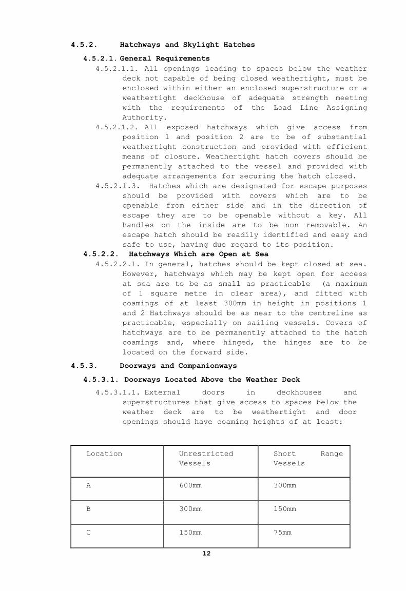
4.5.3.1.1. External doors in deckhouses and
superstructures that give access to spaces below the
weather deck are to be weathertight and door
openings should have coaming heights of at least:
Location Unrestricted
Vessels
Short Range
Vessels
A 600mm 300mm
B 300mm 150mm
C 150mm 75mm
13
Location A The door is in the forward quarter length of the vessel
and is used when the vessel is at sea.
Location B The door is in an exposed forward facing location aft
of the forward quarter length.
Location C The door is in a protected location aft of the
forward quarter length, or an unprotected door on the first tier
deck above the weather deck.
4.5.3.1.2. Weathertight doors should be arranged to open
outwards and when located in a houseside, be hinged at
the forward edge. Alternative closing arrangements
will be considered provided it can be demonstrated
that the efficiency of the closing arrangements and
their ability to prevent the ingress of water will not
impair the safety of the vessel.
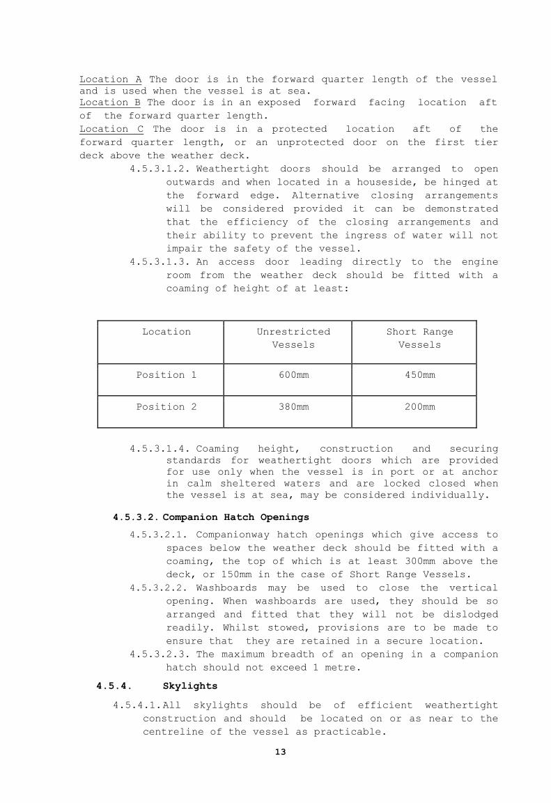
4.5.3.1.3. An access door leading directly to the engine
room from the weather deck should be fitted with a
coaming of height of at least:
Location Unrestricted
Vessels
Short Range
Vessels
Position 1 600mm 450mm
Position 2 380mm 200mm
4.5.3.1.4. Coaming height, construction and securing
standards for weathertight doors which are provided
for use only when the vessel is in port or at anchor
in calm sheltered waters and are locked closed when
the vessel is at sea, may be considered individually.
4.5.3.2. Companion Hatch Openings
4.5.3.2.1. Companionway hatch openings which give access to
spaces below the weather deck should be fitted with a
coaming, the top of which is at least 300mm above the
deck, or 150mm in the case of Short Range Vessels.
4.5.3.2.2. Washboards may be used to close the vertical
opening. When washboards are used, they should be so
arranged and fitted that they will not be dislodged
readily. Whilst stowed, provisions are to be made to
ensure that they are retained in a secure location.
4.5.3.2.3. The maximum breadth of an opening in a companion
hatch should not exceed 1 metre.
4.5.4. Skylights
4.5.4.1. All skylights should be of efficient weathertight
construction and should be located on or as near to the
centreline of the vessel as practicable.
14
4.5.4.2. If they are of the opening type they should be
provided with efficient means whereby they can be secured
in the closed position.
4.5.4.3. Skylights which are designated for escape purposes
should be openable from either side, and in the direction
of escape they are to be openable without a key. All
handles on the inside are to be non-removable. An escape
skylight should be readily identified and easy and safe to
use, having due regard to its position.
4.5.4.4. The skylight glazing material and its method of
securing within the frame should meet an appropriate
national or international standard. Authorized
Organizations rules for "ships" are considered to meet
these requirements.
4.5.4.5. A minimum of one portable cover for each size of
glazed opening should be provided which can be accessed
rapidly and efficiently secured in the event of a breakage
of the skylight.
4.5.5. Portlights
4.5.5.1. Portlights should be of strength appropriate to
location in the vessel and meet an appropriate national or
international standard. Authorized Organizations rules for
“ships" are considered to meet these requirements.
4.5.5.2. In general, all portlights fitted in locations
protecting openings to spaces below the weather deck or
fitted in the hull of the vessel should be provided with a
permanently attached deadlight which is to be capable of
securing the opening watertight in the event of a breakage
of the portlight glazing. Proposals to fit portable
deadlights will be subject to special consideration and
approval by the Competent Authority, having regard for the
location of the portlights and the ready availability of
deadlights. Consideration should be given to the provision
of operational instructions to the Master as to when
deadlights must be applied to portlights.
4.5.5.3. Portlights fitted in the hull of the vessel below the
level of the freeboard deck should be either non-opening
or of a non-readily openable type and be in accordance
with a standard recognised by the Administration. The
lower edge of the portlights should be at least 500mm or
2.5% of the breadth of the vessel, whichever is the
greater, above the all-seasons load line assigned to the
vessel. Portlights of the non-readily opening type must be
secured closed when the vessel is in navigation and
indication provided on the bridge that they are closed.
4.5.5.4. Proposals to fit large portlights (i.e. greater than
0.16 M2) in the main hull below the level of the freeboard
deck will be subject to special consideration and approval
by the Administration, having regard for their location
and strength and their supporting structure and, the
availability of strong protective covers for them. One
item of the special consideration should be operational

15
instructions to the Master as to when the strong
protective covers must be fitted.
4.5.5.5. Portlights should not be fitted in the hull in the way
of the machinery space.
4.5.6. Windows
4.5.6.1. Windows should be of strength appropriate to their
location in the vessel and meet the requirements of an
Authorized Organization rules.
4.5.6.2. For all vessels where the glazing material, glazing
thickness, or fixing of the windows does not meet the
requirements of a recognised standard, windows may be
tested, to the satisfaction of the Administration, at a
minimum of 4 times the required design pressure derived
from an appropriate national or international standard.
Additionally, as a minimum, calculated thicknesses should
meet an Authorized Organization requirements for pleasure
vessels or yachts. For Short Range Vessels, test pressures
may be reduced to 2.5 times the derived design pressure.
4.5.6.3. In general, windows fitted in superstructures or
weathertight deckhouses are to be substantially framed and
efficiently secured to the structure. The glass is to be
of the toughened safety glass type.
4.5.6.4. Where chemically toughened safety glass is used,
windows are to be of the laminated type, the minimum depth
of chemical toughening to be 30 microns on exposed faces.
Regular inspections of the windows, with particular
reference to the surface condition, should form part of
the operational procedures and annual survey by the
Competent Authority.
4.5.6.5. Windows should not be fitted in the main hull below
the level of the freeboard deck.
4.5.6.6. Storm shutters (strong protective covers with
fittings) are required for all windows in the front and
sides of first tier and front windows of the second tier
of superstructures or weathertight deckhouses above the
freeboard deck.
4.5.6.7. When storm shutters are interchangeable port and
starboard, a minimum of 50% of each size should be
provided.
4.5.6.8. Side and front windows to the navigating position
should not be constructed of polarised or tinted glass.
4.5.7. Ventilators and Exhausts
4.5.7.1. Adequate ventilation is to be provided throughout the
vessel. The accommodation is to be protected from the
entry of gas and/or vapor fumes from machinery, exhaust
and fuel systems, where machinery exhaust systems pass
though accommodation they should be fitted in a gas tight
trunk or each space should be fitted with a carbon
monoxide detector, having an alarm provided locally and at
a continuously manned station.
16
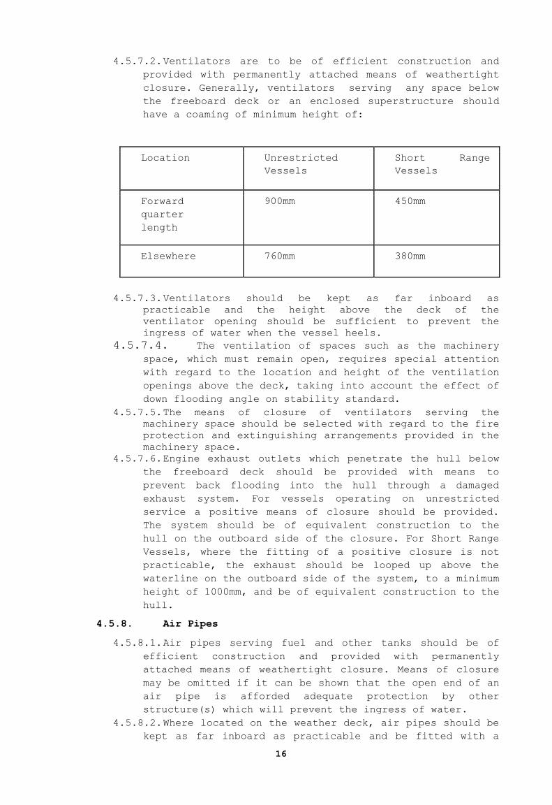
4.5.7.2. Ventilators are to be of efficient construction and
provided with permanently attached means of weathertight
closure. Generally, ventilators serving any space below
the freeboard deck or an enclosed superstructure should
have a coaming of minimum height of:
Location Unrestricted
Vessels
Short Range
Vessels
Forward
quarter
length
900mm 450mm
Elsewhere 760mm 380mm
4.5.7.3. Ventilators should be kept as far inboard as
practicable and the height above the deck of the
ventilator opening should be sufficient to prevent the
ingress of water when the vessel heels.
4.5.7.4. The ventilation of spaces such as the machinery
space, which must remain open, requires special attention
with regard to the location and height of the ventilation
openings above the deck, taking into account the effect of
down flooding angle on stability standard.
4.5.7.5. The means of closure of ventilators serving the
machinery space should be selected with regard to the fire
protection and extinguishing arrangements provided in the
machinery space.
4.5.7.6. Engine exhaust outlets which penetrate the hull below
the freeboard deck should be provided with means to
prevent back flooding into the hull through a damaged
exhaust system. For vessels operating on unrestricted
service a positive means of closure should be provided.
The system should be of equivalent construction to the
hull on the outboard side of the closure. For Short Range
Vessels, where the fitting of a positive closure is not
practicable, the exhaust should be looped up above the
waterline on the outboard side of the system, to a minimum
height of 1000mm, and be of equivalent construction to the
hull.
4.5.8. Air Pipes
4.5.8.1. Air pipes serving fuel and other tanks should be of
efficient construction and provided with permanently
attached means of weathertight closure. Means of closure
may be omitted if it can be shown that the open end of an
air pipe is afforded adequate protection by other
structure(s) which will prevent the ingress of water.
4.5.8.2. Where located on the weather deck, air pipes should be
kept as far inboard as practicable and be fitted with a

17
coaming of sufficient height to prevent inadvertent
flooding. Generally, air pipes to tanks should have a
minimum coaming height of:
Location Unrestricted
Vessels
Short Range
Vessels
On weather
deck
760mm 380mm
Elsewhere 450mm 225mm
4.5.8.3. Air pipes to fuel tanks should terminate at a height of not less than 760mm above either, the top of the
filler pipe for a gravity filling tank or the top of the
overflow tank for a pressure filling tank.
4.5.9. Scuppers, Sea Inlets and Discharges and Other Hull
Penetrations
4.5.9.1. The standards of ICLL should be applied to every
discharge led through the shell of the vessel as far as it
is reasonable and practicable to do so, and in any case,
all sea inlet and overboard discharges should be provided
with efficient shut-off valves arranged in positions where
they are readily accessible at all times.
4.5.9.2. Underwater lights and associated penetrations fitted
in the hull should be approved by the Authorized
Organization.
4.5.10. Materials for Valves and Associated Piping
4.5.10.1. Valves which are fitted below the waterline
should be of steel, bronze or other material having a
similar resistance to impact, fire and corrosion. Non
metallic valves will not normally be considered
equivalent.
4.5.10.2. The associated piping should, in areas as
indicated above, be of steel, bronze, copper or other
equivalent material. Non metallic piping will not normally
be considered equivalent.
4.5.10.3. Where the use of plastic piping is proposed, it
will be considered and full details of the type of piping,
its intended location, and use, should be submitted for
approval; with regard to watertight integrity, any plastic
piping should be above the waterline. Due regard should be
paid to the IMO Fire Test Procedures Code.
4.5.10.4. The use of flexible piping in any location should
be kept to a minimum compatible with the essential reason
for its use. Flexible piping and the means of joining it
to its associated hard piping system should be approved as
fit for the purpose.
18
4.5.11. General Equivalence
4.5.11.1. Where vessels cannot fully comply with the
requirements of this section, equivalent arrangements may
be considered by the Competent Authority. Such proposals
should take into account the following, although this
should not be considered as an exhaustive list:
1. Openings to be kept closed at sea 2. Enhanced Bilge Pumping capacity and additional
bilge alarms
3. Compliance with damage stability if not
already a requirement
4. Provision of dorade boxes or baffle systems to prevent direct ingress of water
5. Alternative ventilation for use in bad weather 6. Consideration of downflooding angle and reduced
risk of green sea loads, i.e. protected position
7. Enhanced survey inspection regime 8. Operational Limitations
4.5.12. Water Freeing Arrangements
4.5.12.1. Water Freeing Standard
4.5.12.1.1. The standards for water freeing
arrangements should comply with ICLL as far as it is
reasonable and practicable to do so in order to
achieve a standard of safety which is at least
equivalent to the standard of ICLL.
4.5.12.1.2. On sailing vessels, where the solid
bulwark height does not exceed 150mm, specific
freeing ports, as defined above, are not
required.
4.5.12.2. Alternative Arrangements
4.5.12.2.1. In individual cases, when the Administration
considers that the requirements of ICLL cannot be met,
the Administration may consider and approve
alternative arrangements to achieve adequate safety
standards. Freeing arrangements may take account of a
reduced permeability and volume of the well, when
compared to a full size well.
4.5.12.2.2. For Short Range Yachts it is considered
that the requirement for freeing port area for a
forward or after well may be reduced by a form factor
equal to the ratio of (actual area well) divided by
(length of well x breadth of well). Dimensions
should be taken at half height of the bulwark. This
may be reduced by 50% providing it can be shown that
the intact stability of the yacht remains acceptable
if the well is flooded to any level up to the bulwark
height and that area provided will allow the well to
drain in less than 3 minutes.
4.5.12.2.3. In considering an individual case, the
Competent Authority will take into account the vessels
past performance in service and the declared area(s)
of operation and any other conditions which restrict
the use of the vessel at sea which will be recorded on
the load line certificate issued to the vessel.
19
4.5.13. Recesses
4.5.13.1. Any recess in the weather deck should be of
weathertight construction and should be self draining
under all normal conditions of heel and trim of the
vessel.
4.5.13.2. A swimming pool or spa bath, open to the
elements, should be treated as a recess.
4.5.13.3. The means of drainage provided should be capable
of efficient operation when the vessel is heeled to an
angle of 10º in the case of a motor vessel, and 30º in
the case of a sailing vessel.
4.5.13.4. The drainage arrangements should have the
capability of draining the recess (when fully charged with
water) within 3 minutes when the vessel is upright and at
the load line draught. Means should be provided to prevent
the backflow of sea water into the recess.
4.5.13.5. When it is not practical to provide drainage
which meets the requirements as stated above, alternative
safety measures may be proposed for approval by the
Administration. Where the above requirements for quick
drainage cannot be met, the effect on intact and damage
stability should be considered taking into account the
mass of water and its free surface effect.
4.6. PROTECTION OF PERSONNEL
4.6.1. Deckhouses and Superstructures
4.6.1.1. The structural strength of any deckhouse or
superstructure should comply with the requirements of an
Authorized Organization, as appropriate to the vessel and
its areas of operation.
4.6.2. Bulwarks and Guardrails
4.6.2.1. Bulwarks and/or guardrails on all accessible decks
should be 1000mm. Any opening should not exceed 380mm.
Where no bulwarks are fitted, or bulwark height is less
than 230mm, the lowest opening should not exceed 230mm.
They should be supported at intervals not exceeding 2.2
metres. Intermediate courses of rails or wires should be
evenly spaced.
4.6.2.2. Satisfactory means (in the form of guard rails, life
lines, gangways or underdeck passages, etc.) should be
provided for the protection of the crew in getting to and
from their quarters, the machinery space and all other
areas used in the necessary work of the craft.
4.6.2.3. Where the function of the vessel would be impeded by
the provision of bulwarks and/or guard rails as specified
above, alternative proposals should be submitted to the
Administration for approval.
4.7. FREEBOARD
4.7.1. Freeboard Assignment
4.7.1.1. The freeboard for the vessel and its marking should

20
be approved by the Competent Authority. The freeboard
assignment should correspond to the deepest loading
condition included in the stability information booklet
for the vessel.
4.7.2. Freeboard Mark and Loading
4.7.2.1. The freeboard mark applied should be positioned port and starboard at amidships on the load line length and may
be an all-seasons mark. The mark should be a permanent
disc and be of contrasting colour to the hull of the
vessel in way of the mark. A vessel should not operate in
any condition which will result in its appropriate
freeboard marks being submerged when it is at rest and
upright in calm water.
4.7.3. Datum Draught Marks
4.7.3.1. Datum draught marks should be provided at the bow and stern, port and starboard, in accordance to Article 8 of
the Cyprus Law 45 / 1963 as amended.
5. RIGGING ON SAILING VESSELS
5.1. General
5.1.1. The condition of the rig should be monitored in
accordance with a Maintenance Manual and a planned
maintenance schedule. The schedule should include, in
particular, regular monitoring of all the gear associated
with safe work aloft and on the bowsprit.
5.2. Masts and Spars and Standing Rigging
5.2.1. Dimensions and construction materials of masts and
spars and dimensions of standing rigging including connection
to chain plates should be in accordance with the requirements
or recommendations of one of the Authorized Organizations or
a recognised national or international standard.
5.2.2. The associated structure for masts and spars
(including chainplates, fittings, decks and floors) should be
constructed to effectively carry and transmit the forces
involved.
5.2.3. Compliance with 5.2.1 and 5.2.2 should be confirmed by
a design review and approval by one of the Authorized
Organizations (e.g. Rig Design Certificate) which is assigned
with the review of the rig.
5.2.4. The Maintenance Manual provided by the mast
manufacturer should be reviewed and approved by the
Authorized Organization which is assigned to review the rig
design.
5.2.5. A physical survey on the rig stepping procedure and
the rig behavior during sea trials is to be carried out by or
on behalf of the Authorized Organization that is involved
with the classification of the vessel’s hull.

21
5.2.6. Annual surveys on the vessel should include reviewing
records and history of rig maintenance measures against the
specifications provided by the maintenance manual.
5.3. Rigging Fittings
5.3.1. The strength of all blocks, shackles, rigging screws,
cleats and associated fittings and attachment points should
exceed the breaking strain of the associated running or
standing rigging.
5.4. Sails
5.4.1. Adequate means of reefing or shortening sail should be
provided.
5.4.2. Sailing vessels operating as Short Range Yachts need
not carry storm canvas.
5.4.3. All other vessels should either be provided with
separate storm sails or have specific sails designated and
constructed to act as storm canvas.
6. MACHINERY
6.1. General Requirements
6.1.1. The machinery and its installation should in general,
meet with the requirements of an Authorized Organization. The
Class Survey or Notation should include, as a minimum,
propulsion and electrical generation machinery and shafting.
For existing and new vessels which operate with periodically
unattended machinery spaces, the machinery and it’s
installation should meet the standards of SOLAS Chapter II-
1/Part E - “Additional requirements for periodically
unattended machinery spaces, so far as is reasonable and
practicable to do so”.
6.1.2. The requirements for main propulsion are based upon
the installation of diesel powered units. When other types of
main propulsion are proposed, the arrangements and
installation should be specially considered. Installation of
gas turbines should take into account the guidance contained
within the IMO High Speed Craft Code and should be to the
satisfaction of the Administration.
6.1.3. Notwithstanding the requirements of paragraph 7.1.1,
in a fuel supply system to an engine unit, where a flexible
section of piping is provided, connections should be of a
screw type or equivalent approved type. Flexible pipes should
be fire resistant/metal reinforced. Materials and fittings
should be of a suitable recognized national or international
standard.
6.2. Installation
6.2.1. Notwithstanding the requirements referred to in 6.1,
the machinery, fuel tanks and associated piping systems and
fittings should be of a design and construction adequate for
the service for which they are intended, and should be so
installed and protected as to reduce to a minimum any danger
to persons during normal movement about the vessel, with due
22
regard being made to moving parts, hot surfaces, and other
hazards.
6.2.2. Means should be provided to isolate any source of
fuel which may feed a fire in an engine space. A fuel shut-
off valve(s) should be provided which is capable of being
closed from a position outside the engine space. The valve(s)
should be fitted as close as possible to the fuel tank(s).
6.2.3. All external high-pressure fuel delivery lines
between the high pressure fuel pumps and fuel nozzles should
be protected with a jacketed tubing system capable of
containing fuel resulting from a high-pressure line failure.
The jacketed tubing system should include means for
collection of leakage and arrangements should be provided for
an alarm to be given in the event of a fuel line failure.
6.2.4. When a glass fuel level gauge is fitted it should be
of the "flat glass" type with self closing valves between the
gauge and the tank.
7. ELECTRICAL INSTALLATIONS
7.1. Installation
7.1.1. Particular attention should be paid to the provision
of overload and short circuit protection of all circuits,
except engine starting circuits supplied from batteries.
7.1.2. Electrical devices working in potentially hazardous
areas, into which petroleum vapor or other hydrocarbon gas
may leak, should be of a type certified safe for the hazard.
7.2. Lighting
7.2.1. Lighting circuits, including those for emergency
lighting, should be distributed through the spaces so that a
total blackout cannot occur due to failure of a single
protective device.
7.2.2. An emergency source of lighting should be provided
which should be independent of the general lighting system.
This source should be sufficient for up to 3 hours duration
and should include navigation light supplies. The lighting is
to provide sufficient lighting for personnel to escape from
the accommodation or working spaces to their muster station,
and launch and board survival craft. Additionally, this
light, supplemented by torches, should be sufficient to
permit emergency repairs to machinery etc.
7.3. Batteries
7.3.1. Batteries of a type suitable for marine use and not
liable to leakage should be used. Areas in which batteries
are stowed should be provided with appropriate ventilation to
prevent an accumulation of gas which is emitted from
batteries of all types.
7.4. Emergency Power
7.4.1. Emergency power should be readily available to supply
the required emergency lighting, radio installation and
navigation aids for a minimum of 3 hours. As a minimum, the
23
navigation aids to be supplied by emergency power to include
GPS, echo sounder and AIS. The emergency power supply should
be adequate to also supply any electrical emergency equipment
fitted, such as fire pumps, bilge pumps, watertight doors,
and rescue boat davit.
7.4.2. The emergency source of power should be independent
of the main power supply, external to the engine room, and
with separate distribution.
7.4.3. The emergency generator, if fitted, should be located
above the uppermost continuous deck but may be located below
this deck provided it is protected from the effects of fire
and flooding. In all cases, the emergency generator should be
separated from main generators and main switchboard by a
division capable of ensuring its continued operation. The
emergency generator should be self contained (independent of
a sea water suction) and readily accessible from the open
deck.
7.4.4. Cables and wiring serving essential or emergency
power, lighting, internal communications or signals should be
routed clear of galleys, machinery places of Category A and
their casings, spaces for storage of petrol, and other high
risk fire areas.
8. STEERING GEAR
8.1. General Requirements
8.1.1. The steering gear and its installation should in
general, meet with the requirements of one of the Authorized
Organizations. In the event that the above requirements
cannot be met on an existing vessel, the Administration may
be requested to consider and approve alternative arrangements
to achieve adequate safety standards. When the steering gear
is fitted with remote control, arrangements should be made
for emergency steering in the event of a failure of such
control.
9. BILGE PUMPING
9.1. General Requirements
9.1.1. The bilge pumping equipment and its installation
should, in general, meet the requirements of an Authorized
Organization.
9.2. Alternative Arrangement
9.2.1. In the event that the above requirements cannot be
met on an existing vessel, the Administration may be
requested to consider alternative arrangements to achieve
adequate safety standards.
9.3. Required Number of Bilge Pumps
9.3.1. All vessels should be provided with at least two

24
fixed and independently powered bilge pumps, with suction
pipes so arranged that any compartment can be effectively
drained when the vessel is heeled to an angle of 10º. For
Short Range Yachts, the second pump and suction pipes may be
portable.
9.4. Capacity of Bilge Pumps
9.4.1. The location of pumps required by 10.2, their
individual power supplies and controls, including those for
bilge valves should be such that, in the event of any one
compartment being flooded at least one of those pumps is
capable of removing water from the flooded space and adjacent
compartments and discharging this via a dedicated discharge
overboard.
9.5. Bilge Level Alarm
9.5.1. In the case of a vessel where the propulsion
machinery space may be unmanned at any time, a bilge level
alarm should be fitted. The alarm should provide an audible
and visual warning in the Master's cabin and in the
wheelhouse. The audible and visual alarm may be accepted
elsewhere if it is considered that such a location may be
more appropriate.
9.6. Pumping and Piping Arrangements
9.6.1. Pumping and piping arrangements for bilges into which
fuel or other oils of similar or higher fire risk could
collect, under either normal or fault conditions, should be
kept clear of accommodation spaces and separate from
accommodation bilge systems. Bilge level alarms meeting the
requirements of 10.5 should be fitted to all such bilges.
10. INTACT AND DAMAGE STABILITY
10.1. All Intact and Damage Stability calculations should be
conducted in compliance with the applicable rules of Authorized
Organizations and International Conventions.
10.2. Permanent Ballast
10.2.1. If used, permanent ballast should be located in
accordance with a plan approved by the Competent Authority
and in a manner that prevents shifting of position. Permanent
ballast should not be removed from the ship or relocated
within the ship without the approval of the Administration.
Permanent ballast particulars should be noted in the ship’s
stability booklet. Attention should be paid to local or
global hull strength requirements from the point of view of
the fitting of additional ballast.
10.3. Intact Stability
10.3.1. Motor vessels
25
10.3.1.1. Stability Criteria
10.3.1.1.1. For Monohull, and multihulls, the curves of
statical stability for seagoing conditions should meet
the provisions of the Intact Stability Code,
Res.MSC.267(85) as amended. If unable to comply with
the Code, the Administration may be consulted for the
purpose of specifying alternative but equivalent
criteria.
10.3.1.2. Loading Conditions
10.3.1.2.1. For the purpose of assessing whether the
stability criteria are met, GZ curves should be
produced for the loading conditions applicable to the
operation of the vessel. The Administration may impose
additional loading conditions to be considered, taking
into account the operation of the vessel.
10.3.2. High Speed Vessels
10.3.2.1. In addition to the criteria above designers and
builders should address the following hazards which are
known to affect vessels operating in planing modes or
those achieving relatively high speeds:
1. directional instability, often coupled to roll and
pitch instabilities;
2. bow diving of planing vessels due to dynamic loss of
longitudinal stability in calm seas;
3. reduction in transverse stability with increasing speed
in monohulls;
4. porpoising of planing monohulls being coupled with
pitch and heave oscillations;
5. generation of capsizing moments due to immersion of
chines in planing monohulls (chine tripping).
10.4. Sailing vessels
10.4.1. Curves of statical stability (GZ curves) for similar
loading conditions as for motor vessels should be produced.
The GZ curves should have a positive range for not less than
90 degrees. For vessels of more than 45m, a range of less
than 90º may be considered but may be subject to agreed
operational criteria.
10.4.2. The angle of steady heel should be greater than 15
degrees.
10.4.3. All regularly used openings for access and for
ventilation should be considered when determining the
downflooding angle. No opening regardless of size which may
lead to progressive flooding should be immersed at an angle
of heel of less than 40°. Air pipes to tanks can, however,
be disregarded.
10.4.4. The vessel should be capable of withstanding a wind
gust equal to 1.4 times the actual wind velocity (i.e. twice
the actual wind pressure) without immersing the down-flooding
openings, or heeling to an angle greater than 60°.
10.5. Damage Stability
10.5.1. It should be noted that vessels in compliance with
Loadline convention, are considered in full compliance with
26
damage stability requirements of the standards.
10.5.2. The following requirements are applicable to all
vessels, other than those operating as Short Range Vessels.
[Whilst Short Range Vessels are not required to meet the
damage stability criteria defined above, ultimate
survivability after minor damage or flooding is recommended.]
10.5.3. The watertight bulkheads of the vessel should be so
arranged that minor hull damage that results in the free
flooding of any one compartment, will cause the vessel to
float at a waterline which, at any point, is not less than
75mm below the weather deck, freeboard deck, or bulkhead deck
if not concurrent.
10.5.4. Minor damage should be assumed to occur anywhere in
the length of the vessel, but not on a watertight bulkhead.
10.5.5. Standard permeabilities should be used in the damage
stability assessment should use percentage permeabilities for
space (a) stores, 60%, (b) accommodation, 95%, and (c)
machinery, 85%.
10.5.6. In the damaged condition, considered above, the
residual stability should be such that any angle of
equilibrium does not exceed 10º from the upright, the
resulting righting lever curve has a range to the
downflooding angle of at least 15º beyond any angle of
equilibrium, the maximum righting lever within that range is
not less than 100mm and the area under the curve is not less
than 0.015 metre radians.
10.6. Elements of Stability
10.6.1. Unless otherwise specified, the lightship weight,
vertical centre of gravity (KG) and longitudinal centre of
gravity (LCG) of a vessel should be determined from the
results of an inclining experiment.
10.6.2. An inclining experiment should be conducted in
accordance with a detailed standard which is approved by the
Administration and, in the presence of an authorized
surveyor.
10.6.3. The report of the inclining experiment and the
lightship particulars derived should be approved by the
Administration prior to its use in stability calculations.
10.6.4. At the discretion of the owner(s)/managing agent(s)
and prior to approval of the lightship particulars by the
Administration, a margin for safety may be applied to the
lightship weight and KG calculated after the inclining
experiment. Such a margin should be clearly identified and
recorded in the stability booklet.
10.6.5. A formal record should be kept in the stability
booklet of alterations or modifications to the vessel for
which the effects on lightship weight and vertical centres of
gravity are offset against the margin.
10.6.6. When sister vessels are built at the same shipyard,
the Administration may accept a lightweight check on
subsequent vessels to corroborate the results of the
inclining experiment conducted on the lead vessel of the
class.

27
10.7. Stability Documents
10.7.1. A vessel should be provided with a stability
information booklet for the Master, that is to be approved by
the Competent Authority. The content of the stability booklet
should conform to the requirements specified by the Intact
Stability Code, Res.MSC.267(85) as amended.
10.7.2. A vessel with previously approved stability
information which undergoes a major conversion or alterations
should be subjected to a complete reassessment of stability
and provided with newly approved stability information.
10.7.3. A major refit or major alteration is one which results
in either a change in the lightship weight of 2% and above
and/or the longitudinal centre of gravity of 1% and above
(measured from the aft perpendicular) or as described by
SOLAS 2017 Amendment (98th)/Chapter II-1/Reg.5.5.
10.7.4. Additionally, unless it can be clearly demonstrated
that no major change has occurred, a lightweight check should
be carried out at the renewal survey required.
10.7.5. Sailing vessels should have, readily available, a copy
of the ‘Curves of Maximum Steady Heel Angle to Prevent
Downflooding in Squalls’, or in the case of a multihull, the
values of maximum advised mean apparent wind speed, for the
reference of the watchkeeper. This should be a direct copy
taken from that contained in the approved stability booklet.
10.7.6. The overall sail area and spar weights and dimensions
should be as documented in the vessel’s stability information
booklet. Any rigging modifications that increase the overall
sail area, or the weight/dimensions of the rig aloft, must be
accompanied by an approved updating of the stability
information booklet.
11. LIFE-SAVING APPLIANCES
11.1. General Requirements
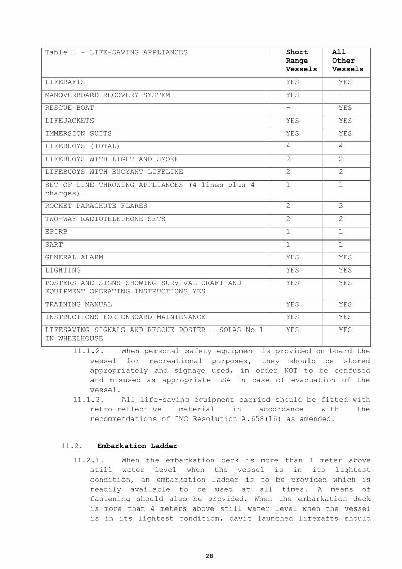
11.1.1. Life-Saving Appliances should be provided in
accordance with Table 1 - Life- Saving Appliances. ALL LSA
equipment on board the vessel should be in compliance with
IMO Life-Saving Appliances Code and IMO Resolution MSC.81(70)
as amended and should be in working order and be ready for
immediate use at all times.
28
Table 1 - LIFE-SAVING APPLIANCES Short
Range
Vessels
All
Other
Vessels
LIFERAFTS YES YES
MANOVERBOARD RECOVERY SYSTEM YES -
RESCUE BOAT - YES
LIFEJACKETS YES YES
IMMERSION SUITS YES YES
LIFEBUOYS (TOTAL) 4 4
LIFEBUOYS WITH LIGHT AND SMOKE 2 2
LIFEBUOYS WITH BUOYANT LIFELINE 2 2
SET OF LINE THROWING APPLIANCES (4 lines plus 4
charges)
1 1
ROCKET PARACHUTE FLARES 2 3
TWO-WAY RADIOTELEPHONE SETS 2 2
EPIRB 1 1
SART 1 1
GENERAL ALARM YES YES
LIGHTING YES YES
POSTERS AND SIGNS SHOWING SURVIVAL CRAFT AND
EQUIPMENT OPERATING INSTRUCTIONS YES
YES YES
TRAINING MANUAL YES YES
INSTRUCTIONS FOR ONBOARD MAINTENANCE YES YES
LIFESAVING SIGNALS AND RESCUE POSTER - SOLAS No 1
IN WHEELHOUSE
YES YES
11.1.2. When personal safety equipment is provided on board the
vessel for recreational purposes, they should be stored
appropriately and signage used, in order NOT to be confused
and misused as appropriate LSA in case of evacuation of the
vessel.
11.1.3. All life-saving equipment carried should be fitted with
retro-reflective material in accordance with the
recommendations of IMO Resolution A.658(16) as amended.
11.2. Embarkation Ladder
11.2.1. When the embarkation deck is more than 1 meter above
still water level when the vessel is in its lightest
condition, an embarkation ladder is to be provided which is
readily available to be used at all times. A means of
fastening should also be provided. When the embarkation deck
is more than 4 meters above still water level when the vessel
is in its lightest condition, davit launched liferafts should
29
be used in combination with at least one launching appliance
for launching.
11.3. Falls for Launching Devices
11.3.1. ALL Falls for launching devices to be used on board the
vessel should be in compliance with the IMO Life-Saving
Appliances Code and should be renewed at intervals not
exceeding the service life recommended by the manufacturer.
11.4. Service and Maintenance
11.4.1. Every inflatable or rigid inflatable rescue boat,
inflatable liferaft and hydrostatic release unit other than a
disposable hydro static release unit should be serviced, at
intervals not exceeding 12 months at a manufacturers approved
service station.
11.4.2. All repairs and maintenance of permanently inflated
rescue boats should be carried out in accordance with the
manufacturers’ instructions;
11.5. Maintenance and Stowage
11.5.1. Maintenance of equipment should be carried out in
accordance with the instructions for onboard maintenance. The
stowage and installation of all life-saving appliances is to
be to the satisfaction of the Administration. Safe evacuation
of the vessel should NOT be obstructed by any hull
projections on the side of the vessel.
11.6. Liferafts
11.6.1. The liferafts carried are to be stowed in GRP
containers and must contain the necessary ”emergency pack".
For Short Range Vessels, or vessels operating within 60 miles
from a safehaven, liferafts provided may be equipped with a
"SOLAS B PACK". For all other vessels, liferafts should be
equipped with a "SOLAS A PACK".
11.6.2. Liferaft approval includes approval of their stowage,
launching and float-free arrangements.
11.6.3. All vessels should have a sufficient number of
liferafts so that in the event of any one liferaft being lost
or rendered unserviceable, sufficient aggregate capacity
remains on either side of the vessel for all persons on board.
This may be achieved by transferring liferafts from one side
to the other. Where liferafts are transferable, this
requirement may be met by the ability of the rafts to be
transferred within 5 minutes, by either 2 or 4 persons.
11.6.4. GRP containers containing liferafts should be stowed on
30
the weather deck or in an open space and fitted with
hydrostatic release units so that the liferafts will float
free of the vessel and automatically inflate.
11.6.5. Liferafts may form part of an approved Marine
Evacuation System (MES). A sufficient number of systems should
be provided, such that in the event of any one entire system
being lost or rendered unserviceable, sufficient aggregate
capacity remains on either side of the vessel for all persons
on board.
11.7. Rescue Boats
11.7.1. Means should be provided for the recovery of a person
from the sea to the vessel when the person is unconscious. [If
an overside boarding ladder or scrambling net is provided the
ladder or net should extend from the weather deck to at least
600mm below the lowest operational waterline.]
11.7.2. All rescue boats covered within this section are to be
equipped to the requirements of the IMO Lifesaving Appliance
Code Ch V/5.1.2. Additionally, rescue boats need not be
capable of being launched from both sides, and means to lower
the boat from within the boat is not required.
11.7.3. Launching stations should be in such positions as
to ensure safe launching having particular regard to
clearance from the propeller and steeply overhanging portions
of the hull and so that, as far as possible, the rescue boat
can be launched down the straight side of the ship whilst
maintaining minimum speed to keep a course.
11.7.4. If stowed forward the launching appliance and rescue
boat should be entirely located in a sheltered position abaft
the vertical extension of the aft most portion of the
collision bulkhead.
11.7.5. Rescue Boat Mandatory Carriage
11.7.5.1. Vessels should be provided with a rescue boat
either meeting the requirements of SOLAS or the following:
11.7.5.2. A boat which is not SOLAS approved but which is
suitable for rescue purposes. The boat may be rigid, rigid
inflated, or inflated, and should have a capacity for not
less than 4 persons, one of which should be assumed to be
lying down. Tubes of rigid inflatable or inflatable boats
should have a minimum of 3 buoyancy compartments. The boat
is to be capable of displaying a highly visible color. If
the equipment as required is stowed in a grab bag, it may
be stowed in the boat or in an easily accessible location
close to the rescue boat.
11.7.5.3. Launching appliances should be either comply and
be approved in accordance with the IMO Lifesaving
Appliance Code except that when a power operated crane is
fitted, it should be capable of operation either by hand
or by an emergency source of power in the event of a main
power failure. The routing of the emergency source of
31
power should be considered in respect of damaged
waterlines and fire or comply with the following
requirements:
11.7.5.4. The appliance should be able to launch the boat
within 5 minutes. When a power operated device is fitted,
it should be capable of operation either by hand or by an
emergency source of power in the event of a main power
failure. The routing of the emergency source of power
should be considered in respect of damaged waterlines and
fire.
11.7.5.5. The launching appliance and its attachments should
be constructed to withstand a static proof load on test of
not less than 2.2 times the maximum working load.
Acceptable factors of safety are 6 for wires, hooks and
sheaves, and 4.5 for the remainder of the launching
appliance. The appliance and its attachments should also
be tested dynamically to 1.1 times the working load. It
should be noted that there is no requirement to recover
the rescue boat provided that the casualty and the boat’s
crew can be recovered on board from the boat in the water.
11.7.6. The design of the falls and winch system should take
account of the principles of IMO Lifesaving Appliances Code Ch
VI/6.1.2
11.7.7. Where it is proposed to use the running rigging on
sailing vessels, the above requirements should also be met.
11.8. Short Range Vessels
11.8.1. Vessels operating as Short Range Vessels should either
comply with requirements of carrying a rescue boat either as a
SOLAS vessel or the following:
11.8.1.1. The vessel should have sufficient mobility and
maneuverability in a seaway to enable persons to be
retrieved from the water. For assessing this ability it is
not considered acceptable to retrieve persons over the
stern of the vessel or adjacent to the propeller(s). The
recovery location should be visible from the conning
position at all times during the recovery, although this
may be achieved by the use of remote controls where
necessary.
11.8.1.2. The vessel should be provided with suitable
equipment and/or arrangements to enable the person(s) to
be recovered without further persons entering the water.
11.9. Lifejackets
11.9.1. One adult SOLAS approved lifejacket should be provided
for each person onboard plus spare adult lifejackets
sufficient for at least 10% of the total number of persons
onboard or two, whichever is the greater. Each lifejacket
should be fitted with a light and whistle.
32
11.9.2. There should be at least two SOLAS approved inflatable
lifejackets for the use of the crew of any rescue boat.
11.9.3. One SOLAS approved child lifejacket or infant
lifejacket should be provided for each child or infant
onboard.
11.10. Immersion Suits
11.10.1. One approved immersion suit should be provided for each
person onboard, these may be of the non-insulated type.
11.10.2. Due consideration should be given to the provision of
appropriate immersion/ thermal protection for children and
infants carried on board.
11.10.3. For cold water areas of operation, the insulated type
should be carried. Reference to Resolution IMO MSC Circular
1046 should be made for assessment of thermal protection.
11.10.4. A vessel constantly engaged on voyages in warm
climates, may be exempted from this requirement.
11.11. Lifebuoys
11.11.1. Lifebuoys port and starboard provided with combined
self-igniting light and self-activating smoke signals should
be capable of quick deployment from the navigating bridge.
11.11.2. The attached buoyant lifeline required on each of two
of the lifebuoys is to have a minimum length of 30 meters.
11.11.3. Each lifebuoy should be marked with the vessel’s name
and Port of Registry.
11.12. EPIRB
11.12.1. An approved EPIRB should be installed in an easily
accessible position ready to be manually released, capable of
being placed in a survival craft and floating free if the
vessel sinks. All EPIRBs should be registered with the
Administration. EPIRBS are to be tested annually and serviced
at not more than five yearly intervals by an approved shore
based maintainer.
11.12.2. Radar Transponders (SART)
11.12.2.1. A SART is to be installed and stowed in an easily
accessible position so that it can rapidly be placed in
any survival craft. Means should be provided in order that
it can be mounted in the survival craft at a height of at
least 1 metre above sea level.
33
11.13. General Alarm
11.13.1. For a vessel not subject to SOLAS this alarm may
consist of the ship's whistle or siren, provided it can be
heard in all parts of the vessel.
11.14. Lighting
11.14.1. Alleyways, internal and external stairways, and exits
giving access to, and including, the muster and embarkation
stations should be adequately lit.
11.14.2. Adequate lighting is to be provided in the vicinity of
survival craft, launching appliance(s) (when provided) and the
overside area of sea in way of the launching position(s). The
lighting should be supplied from the emergency source of
power.
11.15. Life-saving Signals & Rescue Poster
11.15.1. When display space in the wheelhouse is restricted, the
2 sides of a SOLAS No.2 poster (as contained in liferaft
equipment packs) may be displayed in lieu of a SOLAS No. 1
poster.
12. FIRE SAFETY
12.1. Protection of spaces containing vehicles with fuel
12.1.1. Special consideration should be given to safe
conditions of carriage of petrol and other highly flammable
liquids either in hand portable containers/tanks or in the
tanks of vehicles (such as personal water craft, motor cars
and helicopters) which may be transported.
12.2. Miscellaneous
12.2.1. Construction and Arrangement of Saunas
12.2.1.1. All boundaries of the sauna should be of "A" class
divisions, and may include changing rooms, showers and
toilets. The sauna should be insulated to A-30 and B-15
for Short Range Yachts, against other spaces except those
inside of the perimeter of the sauna.
12.2.1.2. Bathrooms with direct access to saunas may be
considered as part of them. In such cases, the door
between sauna and the bathroom need not comply with fire
safety requirements.
12.2.1.3. Wooden linings on bulkheads and ceilings are
permitted. The ceiling above the oven should be lined with
34
a non-combustible plate with an air gap of at least 30mm.
The distance from the hot surfaces to combustible
materials should be at least 500mm or the combustible
materials should be protected (e.g. non- combustible plate
with an air gap of at least 30mm).
12.2.1.4. Wooden benches are permitted.
12.2.1.5. The sauna door should open outwards by pushing.
12.2.1.6. Electrically heated ovens should be provided with
a timer.
12.2.1.7. All spaces within the perimeter of the sauna are
to be protected by a fire detection and alarm system and
an automatic sprinkler system.
12.3. Deep Fat Frying Equipment
12.3.1. Attention is drawn to the requirements in SOLAS II-
2/10.6.4 for fire extinguishing systems for deep fat cooking
equipment. For fryers of up to 15 litres cooking oil capacity,
the provision of a suitably sized Class F extinguisher
together with manual isolation of the electrical power supply
is acceptable.
12.3.2. Control Plan
12.3.2.1. A fire control (general arrangement) plan(s)
should be permanently exhibited for the guidance of the
Master and crew of the vessel. The content of the plan(s)
should adequately show and describe the principal fire
prevention and protection equipment and materials. As far
as practical, symbols used on the plans should comply with
a recognised international standard. The fire control plan
may be a combined Fire & Safety Plan, which should show
the positions of stowage of the life-saving and fire
appliances.
12.3.2.2. For each deck, the plan(s) should show the
position of control stations; sections of the vessel which
are enclosed respectively by "A" class divisions and "B"
class divisions; location of flammable liquid storage (see
14.1.); particulars of and locations of fire alarms, fire
detection systems, sprinkler installations, fixed and
portable fire extinguishing appliances; fireman's
outfit(s); means of access and emergency escapes for
compartments and decks; locations and means of control of
systems and openings which should be closed down in a fire
emergency.
12.3.2.3. The fire plan(s) should be kept up to date. Up-
dating alterations should be applied to all copies of the
plan(s) without delay.
12.3.2.4. A duplicate set of the plan(s) should be
permanently stored in a prominently marked weathertight
enclosure readily accessible to assist non-vessel fire-
fighting personnel who may board the vessel in a fire
35
emergency.
12.3.3. Maintenance and Operation of equipment
12.3.3.1. Instructions valid to the maintenance and
operation of all the equipment and installations onboard
for the fighting and containment of fire should be kept in
one document holder, readily available in an accessible
location.
12.4. Structural Fire Protection
12.4.1. The structural fire protection of all vessels should
be as follows:
1. Passive Fire Protection: Category A, machinery spaces
should be enclosed in an A-30 boundary and for short
range vessels the machinery spaces should be enclosed in
a B-15 boundary.
2. Galleys in all vessels should also be enclosed by B-15 boundary.
3. Openings in 'A' and 'B' Class divisions are to be provided with permanently attached means of closing that are to be
at least as effective for resisting fires as the divisions
in which they are fitted. Windows shall not be fitted in
machinery space boundaries.
4. Where 'A' or ‘B’ Class divisions are penetrated for
the passage of electric cables, pipes, trunks, ducts,
etc., or for girders, beams or other structural members,
arrangements are to be made to ensure that the fire
integrity is not impaired.
5. Where the structure or 'A' Class divisions are required to be insulated, it is to be ensured that the heat from a
fire is not transmitted through the intersections and
terminal points of the divisions or penetrations to
uninsulated boundaries. Where the insulation installed
does not achieve this, arrangements are to be made to
prevent this heat transmission by insulating the
horizontal and vertical boundaries or penetrations for a
distance of 450 mm.
6. Automatic sprinkler systems or equivalent should be
fitted in vessels that do not meet restrictions on
combustible materials.
12.4.2. Forms of construction-Fire divisions
12.4.2.1. Fire divisions using steel equivalent, or
alternative forms of construction may be accepted if it
can be demonstrated that the material by itself, or due to
non-combustible insulation provided, has the fire
resistance properties equivalent to the required divisions
12.4.3. Insulation and Fire Door Frames
12.4.3.1. Insulation is to be such that the temperature of
the structural core does not rise above the point at which
the structure would begin to lose its strength at anytime
during the applicable exposure to the standard fire test
36
as referenced in the IMO FTP Code. For 'A' Class
divisions, the applicable exposure is 60 minutes, and for
'B' Class divisions, the applicable exposure is 30
minutes.
12.4.3.2. For aluminium alloy structures, the insulation is
to be such that the temperature of the structural core
does not rise more than 200°C above the ambient
temperature at any time during the applicable fire
exposure.
12.4.3.3. For composite structures, the insulation is to be
such that the temperature of the laminate does not rise
more than the minimum temperature of deflection under load
of the resin at any time during the applicable fire
exposure. The temperature of deflection under load is to
be determined in accordance with a recognised
international standard.
12.4.3.4. Insulation need only be applied on the side that
is exposed to the greatest fire risk, ie inside the engine
room, a division between two such spaces should however be
insulated on both sides unless it is a steel division.
12.4.3.5. Special attention is to be given to the fixing of
fire door frames in bulkheads constructed of materials
other than steel. Measures are to be taken to ensure that
the temperature of the fixings when exposed to fire does
not exceed the temperature at which the bulkhead itself
loses strength.
12.5. Materials
12.5.1. Except in refrigerated compartments of service
spaces, all insulation (e.g. thermal and acoustic) is to be
of not readily-ignitable materials. Insulation boundaries are
to be arranged to avoid immersion in oil spillages
12.5.2. Pipes penetrating 'A' or 'B' Class divisions are to be
of approved materials having regard to the temperature such
divisions are required to withstand.
12.5.3. Pipes conveying oil or other combustible liquids
through accommodation and service spaces are to be of approved
materials having regard to the fire risk.
12.5.4. Upholstery composites used throughout the vessel
including open decks should be approved in accordance with the
IMO FTP Code, Annex 1, Part 8, or equivalent. This does not
apply to spaces fitted with sprinklers or equivalent fixed
fire extinguishing systems.
12.5.5. Organic foams used in upholstered furniture and
mattresses should be of the combustion modified type.
12.5.6. Suspended textile materials such as curtains or drapes
should be approved in accordance with the IMO FTP Code, Annex
1, Part 7, or equivalent. This does not apply to spaces fitted
with sprinklers or equivalent fixed fire extinguishing
systems.
12.6. Fuel Arrangements
12.6.1. Arrangements for the storage, distribution and
utilisation of oil fuel are to be such as to minimise the risk
37
of fire or explosion.
12.6.2. Oil fuel tanks situated within, or adjacent to, the
boundaries of Category 'A' machinery spaces are not to contain
oil fuel having a flashpoint of less than 60°C.
12.6.3. Oil fuel, lubricating oil and other flammable oils are
not to be carried in fore-peak tanks.
12.6.4. Every oil fuel pipe, which, if damaged, would allow oil
to escape from a storage, settling or daily service tank
situated above the double bottom, should be fitted with a cock
or valve directly on the tank capable of being closed from a
safe position outside the space concerned in the event of a
fire occurring in the space in which such tanks are situated.
12.6.5. Means are to be provided to stop fuel transfer
pumps, oil fired boilers and separators from outside the
machinery space.
12.6.6. Fuel filter bowls should be of metal construction.
12.7. Means of Escape
12.7.1. Purpose
12.7.1.1. The purpose of this section is to provide means of
escape so that persons onboard can safely and swiftly
escape to the liferaft embarkation deck. For this purpose,
safe escape routes should be provided and maintained in a
safe condition, clear of obstacles. Additional aids for
escape should be provided as necessary to ensure
accessibility, clear marking, and adequate design for
emergency situations.
12.7.2. Requirements
12.7.2.1. Stairways, ladders and corridors serving all
spaces normally accessible are to be arranged so as to
provide ready means of escape to a deck from which
embarkation into survival craft may be effected.
12.7.2.2. The arrangement of the vessel should be such
that all compartments are provided with a satisfactory
means of escape. In the case of the accommodation, two
means of escape from every restricted space or group of
spaces should be provided. Concealed escapes and escape
routes are to be clearly marked to ensure ready exit.
12.7.2.3. Category ‘A’ machinery spaces on motor vessels
should also be provided with a minimum of two means of
escape. Other machinery spaces should also have at least
two means of escape as widely separated as possible,
except where the small size of the machinery space makes
it impracticable.
12.7.2.4. The normal means of access to the accommodation
and service spaces below the open deck is to be arranged
so that it is possible to reach the open deck without
passing through a galley, engine room or other space with
a high fire risk, wherever practicable.
12.7.2.5. Where accommodation arrangements are such that
38
access to compartments is through another compartment, the
second escape route is to be as remote as possible from
the main escape route. This may be through hatches of
adequate size, leading to the open deck or separate space
to the main escape route.
12.7.2.6. In exceptional circumstances a single means of
escape may be accepted for spaces, other than
accommodation spaces, that are entered only occasionally,
if the escape route does not pass through a galley,
machinery space or watertight door.
12.7.2.7. No escape route should be obstructed by furniture
or fittings. Additionally, furniture along escape routes
should be secured in place to prevent shifting if the
vessel rolls or lists.
12.7.2.8. All doors in escape routes are to be openable from
either side. In the direction of escape they are all to be
openable without a key. All handles on the inside of
weathertight doors and hatches are to be non removable.
Where doors are lockable measures to ensure access from
outside the space are to be provided for rescue purposes.
12.7.2.9. Lifts are not considered as forming a means of
escape.
12.8. Ventilation Systems
12.8.1. Ventilation fans for machinery spaces and enclosed
galleys are to be capable of being stopped, and main inlets
and outlets of ventilation systems closed, from outside the
spaces being served. This position should not be readily cut
off in the event of a fire in the spaces served.
12.8.2. Ventilation ducts for Category 'A' machinery spaces,
galleys, spaces containing vehicles or craft with fuel in
their tanks, or lockers storing such fuels, are generally not
to pass through accommodation spaces, service spaces or
control stations. Where this is unavoidable, the trunking
should be constructed of steel at least 3mm thick or
equivalent to the satisfaction of the Administration. The
ducting within the accommodation should be fitted with:
12.8.3. [1] fire insulation to A-30 (B-15 on Short Range
Vessels) standard to a point at least 5 metres from the
boundary of the machinery space or galley; and
12.8.4. [2] automatic fire dampers located in the deck or
bulkhead within the accommodation where the trunking passes
from the machinery space or galley into the accommodation.
These automatic fire dampers are also to be manually closable
from outside the galley or machinery space;
12.8.5. Ventilation ducts for accommodation spaces, service
spaces or control stations are not to pass through Category
'A' machinery spaces, galleys, spaces containing vehicles or
craft with fuel in their tanks, or lockers storing such fuels,
unless the ducts are constructed of steel and arranged to
preserve the integrity of the division.
12.8.6. Store-rooms containing highly flammable products
are to be provided with ventilation arrangements that are
separate from other ventilation systems. Ventilation is to be
39
arranged to prevent the build up of flammable vapours at high
and low levels. The inlets and outlets of ventilators are to
be positioned so that they do not draw from or vent into an
area which would cause undue hazard, and are to be fitted with
spark arresters.
12.8.7. Ventilation systems serving Category 'A'
machinery spaces are to be independent of systems serving
other spaces.
12.8.8. All enclosed spaces containing free standing fuel
tanks are to be ventilated independently of systems
serving other spaces.
12.8.9. Ventilation is to be provided to prevent the
accumulation of dangerous concentrations of flammable gas
which may be emitted from batteries.
12.8.10. Ducts provided for tumble driers are to be fitted
with suitably located cleaning and inspection openings.
12.9. Arrangements for Gaseous Fuel for Domestic Purposes
12.9.1. Where gaseous fuel is used for domestic purposes, the
arrangements for the storage, distribution and utilisation of
the fuel is to be such that, having regard to the hazards of
fire and explosion. Hydrocarbon gas detectors and carbon
monoxide detectors should be provided.
12.9.2. Gas cylinders, regulators and safety devices should be
stowed on the open deck (where leakage will not accumulate)
or in a compartment that is vapour-tight to the vessels
interior, and fitted with a vent and drain, so that any gas
which may leak can disperse overboard.
12.10. Fixed Fire Detection and Fire-Alarm Systems
12.10.1. All vessels should be installed with a system to detect
a fire in the space of origin and to provide for an alarm for
safe escape and fire-fighting activity.
12.10.2. A fixed fire detection and fire alarm system is to be
fitted in all enclosed spaces except those containing no
significant fire risk (toilets, bathrooms, void spaces, etc).
Manually operated call points should be placed effectively to
ensure a readily accessible means of notification. The fixed
fire detection and fire-alarm system is to be installed in
accordance with the requirements of SOLAS II-2/7 and the IMO
Fire Safety Systems Code, Chapter 9.
12.10.3. Where a fixed fire-extinguishing system not required by
this Chapter, is installed, the arrangement shall be to the
satisfaction of the Competent Authority.
12.11. Oil Fuel Arrangements
12.11.1. Arrangements for the storage, distribution and
utilization of oil fuel are to be such as to minimize the risk
of fire or explosion.
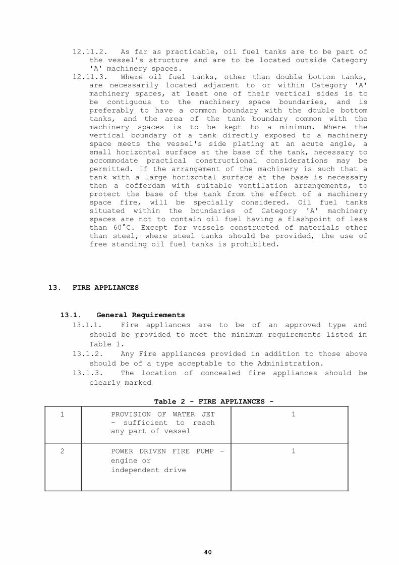
40
12.11.2. As far as practicable, oil fuel tanks are to be part of
the vessel's structure and are to be located outside Category
'A' machinery spaces.
12.11.3. Where oil fuel tanks, other than double bottom tanks,
are necessarily located adjacent to or within Category 'A'
machinery spaces, at least one of their vertical sides is to
be contiguous to the machinery space boundaries, and is
preferably to have a common boundary with the double bottom
tanks, and the area of the tank boundary common with the
machinery spaces is to be kept to a minimum. Where the
vertical boundary of a tank directly exposed to a machinery
space meets the vessel's side plating at an acute angle, a
small horizontal surface at the base of the tank, necessary to
accommodate practical constructional considerations may be
permitted. If the arrangement of the machinery is such that a
tank with a large horizontal surface at the base is necessary
then a cofferdam with suitable ventilation arrangements, to
protect the base of the tank from the effect of a machinery
space fire, will be specially considered. Oil fuel tanks
situated within the boundaries of Category 'A' machinery
spaces are not to contain oil fuel having a flashpoint of less
than 60°C. Except for vessels constructed of materials other
than steel, where steel tanks should be provided, the use of
free standing oil fuel tanks is prohibited.
13. FIRE APPLIANCES
13.1. General Requirements
13.1.1. Fire appliances are to be of an approved type and
should be provided to meet the minimum requirements listed in
Table 1.
13.1.2. Any Fire appliances provided in addition to those above
should be of a type acceptable to the Administration.
13.1.3. The location of concealed fire appliances should be
clearly marked
Table 2 - FIRE APPLIANCES -
1 PROVISION OF WATER JET
– sufficient to reach
any part of vessel
1
2 POWER DRIVEN FIRE PUMP -
engine or
independent drive
1
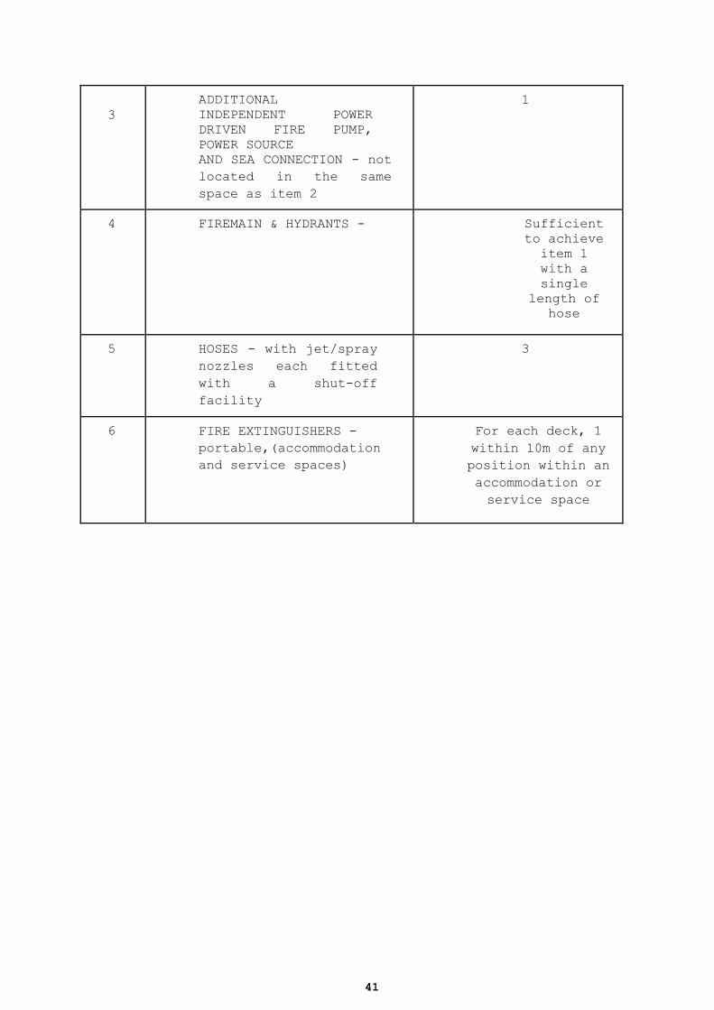
41
3
ADDITIONAL
INDEPENDENT POWER
DRIVEN FIRE PUMP,
POWER SOURCE
AND SEA CONNECTION - not
located in the same
space as item 2
1
4 FIREMAIN & HYDRANTS - Sufficient
to achieve
item 1
with a
single
length of
hose
5 HOSES - with jet/spray
nozzles each fitted
with a shut-off
facility
3
6 FIRE EXTINGUISHERS -
portable,(accommodation
and service spaces)
For each deck, 1
within 10m of any
position within an
accommodation or
service space

42
7 FIRE EXTINGUISHERS -
for a machinery space
of Category A - the
options are:
a fixed fire
extinguishing system
approved in accordance
with the IMO Fire Safety
Systems Code; and
1 portable extinguisher for
oil fires for each 375kw
power; or 2 portable
extinguishers for oil fires
together with either 1 foam
extinguisher of 45l
capacity; or 1 CO2
extinguisher of 16kg
capacity
4 (max)
2 + 1
8 FIREMANS OUTFIT - to
include an approved
breathing apparatus for
each outfit
2
9 FIRE BLANKET - in galley 1
13.2. Specific Requirements
13.2.1. Provision of Water Jet
13.2.1.1. At least one jet of water, from a single length of
hose, should be able to reach any part of the vessel
normally accessible to passengers or crew while the vessel
is being navigated and, any store room or any part of a
storage compartment when empty.
13.2.2. Fire Pumps
13.2.2.1. All vessels should have at least one power driven
pump with a capacity greater than what is estimated by the
following formula.
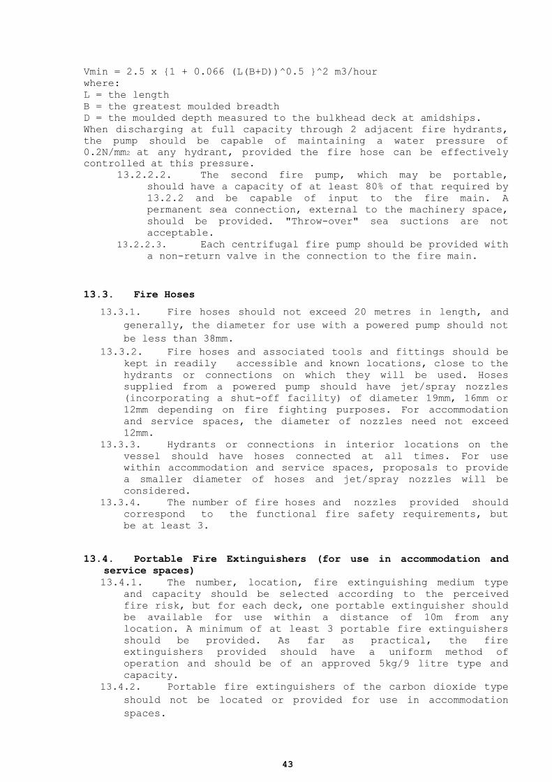
43
Vmin = 2.5 x {1 + 0.066 (L(B+D))^0.5 }^2 m3/hour
where:
L = the length
B = the greatest moulded breadth
D = the moulded depth measured to the bulkhead deck at amidships.
When discharging at full capacity through 2 adjacent fire hydrants,
the pump should be capable of maintaining a water pressure of
0.2N/mm2 at any hydrant, provided the fire hose can be effectively
controlled at this pressure.
13.2.2.2. The second fire pump, which may be portable,
should have a capacity of at least 80% of that required by
13.2.2 and be capable of input to the fire main. A
permanent sea connection, external to the machinery space,
should be provided. "Throw-over" sea suctions are not
acceptable.
13.2.2.3. Each centrifugal fire pump should be provided with
a non-return valve in the connection to the fire main.
13.3. Fire Hoses
13.3.1. Fire hoses should not exceed 20 metres in length, and
generally, the diameter for use with a powered pump should not
be less than 38mm.
13.3.2. Fire hoses and associated tools and fittings should be
kept in readily accessible and known locations, close to the
hydrants or connections on which they will be used. Hoses
supplied from a powered pump should have jet/spray nozzles
(incorporating a shut-off facility) of diameter 19mm, 16mm or
12mm depending on fire fighting purposes. For accommodation
and service spaces, the diameter of nozzles need not exceed
12mm.
13.3.3. Hydrants or connections in interior locations on the
vessel should have hoses connected at all times. For use
within accommodation and service spaces, proposals to provide
a smaller diameter of hoses and jet/spray nozzles will be
considered.
13.3.4. The number of fire hoses and nozzles provided should
correspond to the functional fire safety requirements, but
be at least 3.
13.4. Portable Fire Extinguishers (for use in accommodation and
service spaces)
13.4.1. The number, location, fire extinguishing medium type
and capacity should be selected according to the perceived
fire risk, but for each deck, one portable extinguisher should
be available for use within a distance of 10m from any
location. A minimum of at least 3 portable fire extinguishers
should be provided. As far as practical, the fire
extinguishers provided should have a uniform method of
operation and should be of an approved 5kg/9 litre type and
capacity.
13.4.2. Portable fire extinguishers of the carbon dioxide type
should not be located or provided for use in accommodation
spaces.

44
13.4.3. Except for portable extinguishers provided in
connection with a specific hazard within a space when it is
manned (such as a galley), portable extinguishers generally
should be located external to, but adjacent to, the entrance
of the space(s) in which they will be used. Extinguishers
should be stowed in readily accessible and marked locations.
13.4.4. Spare charges should be provided onboard for at least
50% of each type and capacity of portable fire extinguisher
onboard. When an extinguisher is not of a type which is
rechargeable when the vessel is at sea, an additional portable
fire extinguisher of the same type (or its equivalent) should
be provided.
13.5. Fire Extinguishing in Machinery Spaces
13.5.1. In a machinery space containing an oil fired boiler,
oil fuel settling tank or oil fuel unit, a fixed fire
extinguishing system complying with the IMO Fire Safety
Systems Code should be installed.
13.5.2. Portable fire extinguishers should be installed and the
number, location, fire extinguishing medium type and capacity
should be selected according to the perceived fire risk in the
space.
13.5.3. In any case, portable fire extinguishers for
extinguishing oil fires should be fitted as follows (a) in a
boiler room, at least 2, (b) in a space containing any part of
an oil fuel installation, at least 2 and (c) in a firing
space, at least 1.
13.6. Alternative Design and Arrangements
13.6.1. Vessels may follow Alternative Design and Arrangements.
An engineering analysis shall be prepared and submitted to the
Competent Authority, based on the guidelines (Refer to the Guidelines
on alternative design and arrangements for fire safety
(MSC/Circ.1002))and shall include, as a minimum, the following
engineering analysis elements:
1. determination of the ship type and space(s) concerned;
2. identification of prescriptive requirement(s) with which
the ship or the space(s)will not comply;
3. identification of the fire and explosion hazards of the
ship or the space(s)concerned, including;
4. identification of the possible ignition sources; (i)
5. identification of the fire growth potential of each space
concerned;
6. identification of the smoke and toxic effluent generation
potential for each space concerned;
7. identification of the potential for the spread of fire,
smoke or of toxic effluents from the space(s) concerned to
other spaces;
8. determination of the required fire safety performance
criteria for the ship or the (d)space(s) concerned
addressed by the prescriptive requirement(s) in particular:
45
9. performance criteria shall be based on the fire safety
objectives and on (i)the functional requirements of this
chapter;
10. performance criteria shall provide a degree of safety not
less than that (ii)achieved by using the prescriptive
requirements; and
11. performance criteria shall be quantifiable and measurable;
(iii)
12. detailed description of the alternative design and
arrangements, including a list (e)of the assumptions used
in the design and any proposed operational restrictions or
conditions; and
13. technical justification demonstrating that the alternative
design and arrangements meet the required fire safety
performance criteria.
14. RADIO
14.1. Radio Communications: The Global Maritime Distress and Safety
System (GMDSS)
14.1.1. 1Each vessel should carry sufficient radio equipment to
perform the following distress and safety communications
functions throughout its intended voyage:
1. transmitting ship to shore distress alerts by at least two
separate and independent means, each using a different
radio communication service;
2. receiving shore-to-ship distress alerts;
3. transmitting and receiving ship-to-ship distress alerts;
4. transmitting and receiving search and rescue co-
ordinating communications;
5. transmitting and receiving on-scene communications; 6. transmitting and receiving signals for locating by radar;
7. transmitting and receiving maritime safety information;
and
8. transmitting and receiving bridge-to-bridge
communications.
14.2. Vessels should carry the following Radio equipment fulfilling
distress and safety communication functions for voyages in Sea
Areas A1, A2, A3 and A4.
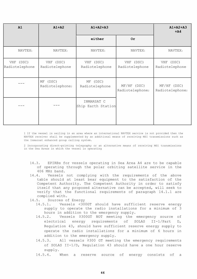
46
A1 A1+A2 A1+A2+A3 A1+A2+A3
+A4
either Or
NAVTEX1 NAVTEX1 NAVTEX1 NAVTEX1 NAVTEX1
VHF (DSC)
Radiotelephone
VHF (DSC)
Radiotelephone
VHF (DSC)
Radiotelephone
VHF (DSC)
Radiotelephone
VHF (DSC)
Radiotelephone
--- MF (DSC)
Radiotelephone2
MF (DSC)
Radiotelephone
MF/HF (DSC)
Radiotelephone2
MF/HF (DSC)
Radiotelephone2
---
---
INMARSAT C
Ship Earth Station
1 If the vessel is sailing in an area where an international NAVTEX service is not provided then the
NAVTEX receiver shall be supplemented by an additional means of receiving MSI transmissions such as
the Inmarsat enhanced group calling system.
2 Incorporating direct-printing telegraphy or an alternative means of receiving MSI transmissions
in the Sea Areas in which the vessel is operating
14.3. EPIRBs for vessels operating in Sea Area A4 are to be capable
of operating through the polar orbiting satellite service in the
406 MHz band.
14.4. Vessels not complying with the requirements of the above
table should at least bear equipment to the satisfaction of the
Competent Authority. The Competent Authority in order to satisfy
itself that any proposed alternative can be accepted, will seek to
verify that the functional requirements of paragraph 14.1.1 are
complied with.
14.5. Sources of Energy
14.5.1. Vessels <300GT should have sufficient reserve energy
supply to operate the radio installations for a minimum of 3
hours in addition to the emergency supply.
14.5.2. Vessels ≥300GT NOT meeting the emergency source of
electrical energy requirements of SOLAS II-1/Part D,
Regulation 43, should have sufficient reserve energy supply to
operate the radio installations for a minimum of 6 hours in
addition to the emergency supply.
14.5.3. All vessels ≥300 GT meeting the emergency requirements
of SOLAS II-1/D, Regulation 43 should have a one hour reserve
supply.
14.5.4. When a reserve source of energy consists of a
47
rechargeable accumulator battery, a means of automatically
charging such batteries should be provided, which is capable
of recharging them to minimum capacity requirements within 10
hours which should include a visual and audible charger
failure device.
14.5.5. The siting and installation of accumulator batteries
should ensure the highest degree of service and safety.
14.6. Radio Personnel
14.6.1. A vessel should carry at least one person qualified for
distress and safety radiocommunication purposes, who should
hold a certificate of competence acceptable to the relevant
authority.
14.7. Availability of Equipment
14.7.1. On vessels of 300GT and above the availability of radio
installations should be ensured by using such methods as
duplication of equipment, shore-based maintenance or at sea
electronic maintenance capability.
15. NAVIGATION LIGHTS, SHAPES AND SOUND SIGNALS
15.1. Every vessel should comply with the requirements of the
International Regulations for Preventing Collisions At Sea, 1972,
as amended. All navigation lights should be provided with main and
emergency power supply.
16. NAVIGATIONAL EQUIPMENT
16.1. The Requirements, as specified in SOLAS 1974, as amended,
Chapter V, as applicable based on ship’s size, should be complied
with unless the Flag Administration specifies otherwise.
17. ANCHORS AND CABLES
17.1. Equipment
17.1.1. Vessels will be considered to have adequate equipment
if fitted out in accordance with standards for such equipment,
set by an Authorized Organization.
48
17.1.2. Vessels not equipped in accordance with 20.1.1 may be
specially considered by the Administration, provided full
information is submitted for approval.
17.1.3. All vessels are to have at least 2 anchors, one of
which must be ready for use at all times. Any powered
deployment system should be connected to an emergency power
supply or be capable of being manually operated.
17.2. Sailing Vessels
17.2.1. The sizing of anchors and cables for sailing vessels
should take into account the additional windage effect of the
masts and rigging.
17.2.2. Typically, for square rigged sailing vessels of up to
50 metres in length, experience based guidance on approximate
increase in anchor mass and cable strength is typically 50%
above the requirements for a typical motor vessel having the
same total longitudinal profile area of hull and
superstructure as the square rigged sailing vessel under
consideration.
18. MARITIME LABOUR
18.1. The provisions of Maritime Labour Convention as amended
through the ratifying Law 6(III)/2012 and related DMS circulars,
are applicable for category A,B,C and D vessels. The competent
authority will consider any requests for exemptions and or
equivalent provisions as it is allowed by the pre-mentioned Law.
19. MEDICAL STORES
19.1. A vessel should carry medical stores as required by the
Competent Authority (Law 175(I)/2002 and P.I. 223/2010). It is
noted that pleasure vessels, not manned with professional
seafarers, do not fall under the provisions of this law.
20. SPECIALIZED CRAFTS/EQUIPMENT
20.1. Tenders
20.1.1. When a vessel carries a rigid or inflatable tender, it
49
should be fit for its intended use. Safety equipment should be
provided in the tender as appropriate to its intended range
and area of operation. Each tender should be clearly marked
with the number of persons that it can safely carry, and the
name of the parent vessel. All tenders capable of carrying
more than 6 persons, should follow where practicable, the
national requirements of high speed pleasure crafts.
20.2. Helicopters
20.2.1. When provision is made for helicopter operations to or
from the vessel, the helicopter landing area should be located
on an appropriate area of the weather or superstructure deck,
or on a purpose built landing area permanently attached to the
vessel or structure, providing;
1. the structural strength of the helicopter landing area is designed and constructed according to an Authorized
Organization rules on helicopter landing areas for vessels
and a Certificate of Compliance is issued by the relevant
Authorized Organization;
2. the requirements for helicopter facilities in SOLAS II-2 are complied with in full;
3. helicopter operations to/from the vessel are restricted to within the weather, pitch, roll, and heave limits for
the vessel as defined where appropriate in the relevant
operating rules;
4. the helicopter landing area is designed for the largest helicopter which it is intended to use; and
5. the operational procedures for the vessel fully reflect the above.
20.2.1.1. If it is intended to provide hangar and/or
refuelling facilities for a helicopter whilst it is on
board the vessel, agreement from both the Authorized
Organization and the Competent Authority should be
obtained.
20.2.1.2. The minimum safe landing area dynamic load
bearing capability should be 2.5 (two and a half) times
the Maximum Take-Off Mass (MTOM) of the heaviest helicopter
intended to use the landing area. This may only be reduced,
subject to agreement from both the Authorized Organization
and the Competent Authority.
20.2.2. The officer(s) in charge of each helicopter landing
area operations team should be in possession of an Offshore
Petroleum Industry Training Organisation (OPITO) Approved
Offshore Helicopter Landing Officer (HLO) certificate. All
other crew assigned duties within the helicopter landing area
operations team(s) should be in possession of an OPITO
Approved Offshore Emergency Helideck Team Member certificate.
Certification from an equivalent course approved by the
Administration will also be accepted. All helicopter
operations certification should be in date.
20.2.3. All crew on board should undergo familiarisation
training regarding helicopter operations on board and it is
50
recommended that all crew undertake helicopter crash
survivability (“dunker”) training at a recognised OPITO
training centre, prior to commencement of duties.
20.2.4. Ship to shore and ship to helicopter communications
procedures, ship operating procedures, and guidance on
helicopter emergencies should be included in the Safety
Management System of the vessel.
20.2.5. Refueling of the helicopter while engines and rotors
are running is prohibited.
20.3. Pilot for Vessel
20.3.1. Boarding arrangements provided for pilots should have
due regard for SOLAS Chapter V, Regulation 23 and IMO
Resolution A.1045 (27) "Pilot transfer arrangements",
International Maritime Pilots’ Association (IMPA)
recommendations, or any documents replacing them.
20.4. Gangway and Accommodation Ladders
20.4.1. A safe means of access is to be provided at all times
when in port, either deployed or available for deployment. If
the safe means of access is not deployed, there should be a
means provided for communication between those on the quay and
those on board.
20.4.2. When provided, gangways, passerelles, and accommodation
ladders should be manufactured to a recognised national or
international standard, and be clearly marked with the
manufacturer's name, the model number, the maximum design
angle of use and the maximum safe loading (by number of
persons and by total mass). Side screens or handrail(s) should
be provided on both sides.
20.4.3. Where gangways, passerelles or ladders do not comply
with national or international standards, a manufacturer’s
test load certificate should be provided. Alternatively
practical tests may be carried out to the satisfaction of the
Administration. In all cases the maximum design angle, maximum
number of persons, and the maximum total mass should be
clearly marked, and are to be used in accordance with the
manufacturer’s instructions.
20.4.4. Access equipment and immediate approaches to it should
be adequately illuminated.
20.5. Submersible Craft
20.5.1. Registration, construction and operation of submarines
are allowed to be registered in the Cyprus Registry. They may
be permanently carried by a parent vessel and hence it should
be registered as part of the equipment on board the parent
vessel, or it may be registered as a stand alone vessel which
51
may be carried by a specific vessel for specific operations.
If the submersible craft is carried permanently by a parent
ship, both vessels must be registered under the same registry.
A submersible registered in the Republic of Cyprus is allowed
to be carried temporarily by a parent vessel for specific
operations, subject to the approval of the State of Registry
of the parent vessel.
20.5.2. Submersible crafts, registered in the Republic of
Cyprus are subject to the provisions of IMO MSC.1 Circular
981, “Guidelines for the design, construction and operation of
passenger submersible craft”, in addition to all other
relevant provisions included in these technical standards.
20.5.3. Submersible Craft carried on vessels should comply with
the following:
1. They should be constructed and maintained in accordance with the rules of an Authorized Organization, applicable national
regulations and be suitable for the intended use.
2. Supporting equipment should be constructed and maintained in accordance with the rules of an Authorized Organization and
any applicable national regulations. The maximum safe working
load of the equipment and maximum sea state in which the
craft may be launched are to be stated.
3. A safety management system which may be separate from any system operated by the parent vessel, including an operations
manual, must be in place, and subject to annual audit.
4. Following satisfactory survey and audit, certification for
safety of submersible craft and its support equipment should
be issued, and is subject to annual survey.
5. Maintenance should be carried out by the manufacturer or an organisation or person accepted by the Administration at
intervals specified by the manufacturer.
6. Operating crew to have adequate theoretical and practical
training for the type of submersible craft onboard, and have
demonstrated ability to operate it.
21. MARINE ENVIRONMENT
21.1. MARPOL
21.1.1. Prevention of Pollution by Oil (MARPOL ANNEX I)
21.1.1.1. Ships should comply with all the requirements of
MARPOL ANNEX I, as appropriate. It is the owner’s
responsibility to comply with Administration / coastal/
port state requirements.
21.1.1.2. Ships under 400 GT, should have holding tanks of
adequate capacity for the retention of oily mixtures
onboard and means of disposal to the reception facilities
as minimum measures.
21.1.1.3. Holding tanks capacity should be calculated based
on the formula (7 x 0.5% of total daily fuel oil
consumption in ltrs )+ 0.10% of total engine lubricant
capacity in ltrs , for ships engaged on short
52
international voyages and (14 x 0.5% of total daily fuel
oil consumption in ltrs) + 0.10% of total engine lubricant
capacity in ltrs for the ships other than those engaged on
short international voyages.
21.1.1.4. Ships under 400 GT should have a nominated pump
for any transfer of oily bilge water, not connected to any
other system of the ship or used for any other purpose.
21.1.2. Prevention of Pollution by Sewage from ships (MARPOL
ANNEX IV)
21.1.2.1. Ships should comply with the requirements of
MARPOL ANNEV IV, as appropriate.
21.1.2.2. It is owner ‘s responsibility to comply with
additional requirements of Administration / coastal / port
state.
21.1.2.3. All ships should comply with the requirements of
MAPROL / ANNEX IV – REGULATION 11, for discharge of sewage
into the sea.
21.1.2.4. Ships of less than 400 GT which are certified to
carry more than 15 persons should comply with all
requirements of MARPOL ANNEV IV.
21.1.2.5. Ships of less than 400 GT certified to carry less
than 15 passengers should be furnished, with a designated
holding tank for retention of sewage and means of disposal
to the reception facilities as minimum measures.
21.1.3. Prevention of Pollution by Garbage from ships (MARPOL
ANNEX V)
21.1.3.1. The provisions of MARPOL ANNEX V shall apply to
all ships.
21.1.3.2. Discharge of Garbage shall be in accordance with
the MARPOL ANNEX V Regulation 3,4 and 6.
21.1.3.3. All Ships shall display placards which notify the
persons (crew - passengers) onboard for the discharge
requirements of Regulation 3,4,6 of MARPOL ANNEX V as
appropriate.
21.1.3.4. Ships of 100 GT and above and every ship which is
certified to carry 15 or more persons shall carry a
Garbage Management Plan which the crew shall follow. This
plan shall be based on the guidelines developed by the
Organization and written in the working language of the
crew.
21.1.3.5. Ships of 400 GT and above and every ship which is
certified to carry 15 or more persons shall be provided
with a Garbage Record Book. The Garbage Record Book shall
be maintained as per the requirements of MARPOL ANNEX V.
21.1.4. Prevention of Air Pollution from ships (MARPOL ANNEX
VI)
21.1.4.1. Every ships of 400 GT and above shall be subject
to the surveys as specified at MARPOL ANNEX VI –
REGULATION 5.
53
21.1.4.2. Ships of 400 GT and above shall maintain an
International Air Pollution Prevention Certificate as
required by MARPOL ANNEX VI – REGULATION 6.
21.1.4.3. Ships equipped with marine diesel engine with a
power output of more than 130 Kw or with marine diesel
engine with a power output of more than 130 kW which
undergoes a major conversion on or after 1 January 2000,
except when demonstrated to the satisfaction of the
Administration that such engine is an identical
replacement to the engine which it is replacing shall
comply with MAPROL / ANNEX VI – REGULATION 13.
21.1.4.4. Ships which are equipped with engine as provided
by Regulation 13.1 of MAPROL ANNEX VI shall maintain
Engine IAPPC as appropriate.
21.1.4.5. All Ships shall comply to Reg. 12 of Annex VI of
MARPOL and maintain an Ozone Depleting Substances Record
Book.
21.1.4.6. All ships shall comply with the MARPOL / ANNEX VI
– REGULATION 14, as amended.
21.1.4.7. All ships should maintain onboard the Bunker
Delivery Note (BDN), as per MARPOL / ANNEX VI -REGULATION
18.5 & 18.6.
21.2. Antifouling System Requirements
21.2.1. All vessels should comply with the hull Anti-Fouling
System Convention requirements.
21.2.2. Ships of 24 meters or more in length but less than 400
GT engaged in International voyages shall carry a Declaration
on Anti-Fouling System.
21.3. Ballast Water Management Requirements
21.3.1. Ballast Water Management Convention (BWMC) shall apply
to all ships.
21.3.2. Pleasure craft used solely for recreation or
competition or craft used primarily for search and rescue,
less than 50 meters in length overall, and with a maximum
Ballast Water capacity of 8 cubic meters, shall conduct
Ballast Water Management in accordance with the G.3 Guidelines
Resolution of MEPC.123(53).
21.3.3. Ballast Water Management Convention shall not apply to
ships which are falling under the provisions of Article 3-
Application of BWMC.
21.3.4. All ships constructed before 08/09/2017, with Ballast
Capacity more than 8 cubic meters and less than 400 GT shall:
21.3.4.1. Conduct ballast water management that at least
meets the standard described in BWMC / ANNEX / Regulation
D-2 not later than 08 September 2024.
21.3.4.2. Maintain and implement a Ballast Water Management
Plan, as required by BWMC.
54
21.3.4.3. Maintain a Ballast Water Record Book, as required
by BWMC
21.3.4.4. Conduct Ballast Water exchange in accordance with
the BWMC / ANNEX / Regulation D-1, until meets the
standards described in BWMC / ANNEX / Regulation D-2.
21.3.5. Every ship of 400 GT and above shall be subject to
survey as specified at BWMC / ANNEX / REGULATION E-1, as
amended and maintain the International Ballast Water Management
Certificate as required by BWMC / ANNEX / REGULATION E-2.
21.4. Ship Recycling Requirements
21.4.1. Every ships of 500 GT and above shall comply with the
provisions of Regulation EU 1257 / 2013 on Ships Recycling
Requirements.
21.4.2. Ships which are excluded from the scope of Regulation
(less than 500 GT) are encouraged to adopt appropriate
measures to ensure that act in a manner that is consistent
with this Regulation, in so far as is reasonable and
practicable.
22. MANNING
22.1. Category A, B and D vessels are required to have onboard
Minimum Safe Manning Document. Voluntary provisions are in place
for Category C vessels. The relevant provisions and the
application for the issuance of Minimum Safe Manning Document can
be found in Annex 1.
22.2. Crew members employed, should be included in the crew list
required for the vessel, should have received on board
familiarisation training as required by STCW, and should not be
assigned duties on the muster list unless they received
appropriate training. All crew members are required to have
successfully completed approved STCW Basic Safety Training.
23. Survey and Certification
23.1. General
23.1.1. The Administration may authorize Organizations to
perform approvals of drawings, calculations, materials,
equipment, procedures and manuals, intact and damage stability
calculations and documentation, plans and statements as well
as to survey and inspect vessels and issue relevant
55
certification on its behalf, in accordance with the provisions
of the present technical standards.
23.1.2. Subject to the provisions of the following paragraph,
the shipowner and the operator of a Cyprus ship shall
individually bear the obligation to ensure that the ship be
constructed, equipped and maintained in conformity with the
rules and procedures of the Organization acting on behalf of
the Republic, with respect to the hull, machinery and
electrical and control installation requirements. Subject to
subsection 23.1.3, the shipowner and the operator of a Cyprus
ship shall individually bear the obligation to furnish the
ship with a valid class certificate issued by an Authorized
Organisation.
23.1.3. The Administration may, by virtue of an order, issue
and apply rules it considers equivalent to those of a
recognised organisation. In such case: (i) subsection (1)
shall not apply; and (ii) the shipowner and operator of a
Cyprus ship individually bear the obligation to ensure that
the said ship complies with the aforementioned rules.
23.1.4. All vessels subject to these technical standards are
required to be surveyed and certificated in accordance with
the International Load Line Convention. Vessels which are over
400GT fall under the provisions of the MARPOL Convention. All
vessels of over 300GT (except from category C) are also
required to be surveyed and certificated under the radio
requirements of SOLAS. All other vessels subject to these
technical standards should be surveyed in accordance with
relevant applicable rules and regulations of an Authorized
Organization.
23.1.5. Statutory work may be undertaken by surveyors of the
Competent Authority or by surveyors of an Authorized
Organization.
23.1.6. A vessel to which the International Conventions apply
must be surveyed and certificated appropriately in accordance
to those applicable conventions. All requests for survey and
certification must be made to the Administration (or the dully
Authorized Organization acting on its behalf) or the
appropriate organisation or Private Body in relation to radio
installations.
23.1.7. Initial Survey (including new-building commercial
vessels)
23.1.8. Vessels are required to be initially surveyed and
issued with the applicable certificates.
23.1.9. Indicative list with the required certificates is
included in Annex II. The issuance and validity of each
certificate is subject to the requirements / conditions of the
relevant instrument.
23.1.10. The Statement of Compliance with the present standards,
56
is issued with a five-year period of validity and is endorsed
annually based on satisfactory results of a relevant survey,
which shall be conducted within a three months window from the
anniversary date. The provisions of SOLAS 74 as amended /
Chapter I / Regulation 14, regulating the validity of
certificates for cargo ships, are adopted mutatis mutandis for
the Statement of Compliance with the present standards in
order to regulate its’ validity. If the survey is completed
within the prescribed window, the anniversary date of the
certificate i.e. the day and the month of each year, will
remain the same. The owners are prompted to keep the surveys
for the issuance of this certificate harmonized with the
surveys required for the issuance / endorsement of other
certificates. In case the survey is not completed within the
window the Competent Authority should be conducted for
instructions. The Competent Authority will consider any
reasonable request in order to facilitate the harmonization of
the surveys.
23.1.11. Alternative Inspection Schemes for Category C vessels
Notwithstanding the above, Category C vessels not falling
within the scope of certification of the International
Conventions ratified by the Republic of Cyprus (i.e. below
400GT), the Competent Authority may consider alternative
inspection schemes proposed by the owners which do not
represent inferior level of inspections compared to that
provided by the above standards. Any alternative inspection
scheme proposed will observe a period of validity and surveys
as outlined by 23.1.10.
The competent Authority shall evaluate all the surrounding
factors of the proposal with the purpose of ensuring
equivalent safety levels with those of the standards and may
impose relevant restrictions/conditions.
Upon positive consideration of the proposal, the Competent
Authority will grant its consent to the proposed inspection
scheme and upon receipt of the relevant inspection reports and
notification, the Statement of Compliance shall be issued by
the Competent Authority.
The competent Authority may in due course issue guidelines on
such alternative schemes.
24. ACCIDENT INVESTIGATIONS
24.1. The conduct of the parties involved in relation to an
accident can be found in Annex 3.
57
25. SAFETY MANAGEMENT SYSTEM
25.1. The vessels, for which the provisions of the ISM Code are not
mandatory under SOLAS, a Management System should be established,
addressing at least the Issues, as described in Annex 1. Category
C vessels are urged to employ a Safety Management System as far as
practicable. The owner is the responsible entity for the
developing and implementation of the Safety Management System or
another person or entity, who / which has assumed the
responsibility for operation of the ship from the Shipowner and
who on assuming such responsibility has agreed to take over all
the duties and responsibility imposed by the Safety Management
System requirements. In this respect the owner and the person /
entity should be able to provide at any time and when requested
evidence of their agreement and terms thereof.
25.2. The safety management system can be found in Annex 4.
26. Serious discrepancies / failure of compliance with the standards
26.1. In case of serious discrepancies / failure of compliance with
the Technical Standards is identified, the Shipping Deputy
Ministry may initiate the procedure as prescribed in article 6A of
Cyprus Law 45/1963, for a possible revocation of the Cyprus
character of a ship.

58
59
ANNEXES
Annex 1 – Minimum Safe Manning
A1.1. MINIMUM SAFE MANNING
A1.1. Minimum Safe Manning of Commercial Vessels
A1.1.1. IMO Resolution A.1047(27) adopted on the 30th November
2011 defines the principles of Safe Manning to ensure the safe
operation of, and prevention of pollution from, ships to which
the Convention applies.
A1.1.2. The Administration may choose to adopt these
arrangements in full, or modify these arrangements to meet
particular operational circumstances.
A1.1.3. All sea going commercially operated vessels and sail
training vessels of more than 24 metres in Tonnage Length
should carry an appropriate number of qualified Deck and
Engineer Officers to ensure a degree of safety at least
equivalent to that established by the IMO guidelines.
A1.1.4. Training vessels must be properly and safely manned at
all times, both at sea and if necessary in port, by a
sufficient number of experienced and competent personnel to
ensure that trainees are adequately supervised giving
particular consideration to the number, age, sex of the
trainees. All training should be properly organised with
clearly detailed objectives and outcomes.
A1.1.5. The Administration should ensure that all vessels are
safely and sufficiently manned in relation to the nature of
their operation with the responsibilities placed on companies
owning or operating seagoing vessels, to ensure that their
vessels are manned with personnel of appropriate grades who
have been properly trained and certificated.
A1.1.6. The numbers of certificated officers and certificated
and non-certificated ratings, must be sufficient to ensure safe
and efficient operation of the vessel at all times.
A1.1.7. The guidelines place a duty on the owner or operator to
provide the master of a vessel with the necessary resources to
comply with the manning requirements.
A1.2. Minimum Safe Manning Document
A1.2.1. All vessels of Categories A, B & D in compliance with
these regulations should fully comply with the national
legislation on the minimum manning for the safety of
navigation. All vessels should carry a valid Minimum Safe
Manning Document.
A1.2.2. Owners of Category C who wish to maintain voluntary
compliance with minimum manning requirements may apply for the
issuance of a Minimum Safe Manning Document.
60
A1.3. Application for a Minimum Safe Manning Document
A1.3.1. Any application for a Minimum Safe Manning Document
should be made by the owner, or a person authorised to act on
their behalf, to the flag Administration of the vessel.
A1.3.2. For Category A & D vessels must be used the application
form as per SDM Circular 12/2017 at its latest edition. The
application must include proposals as to the number and the
qualifications of the crew, which the owner or a person
authorised to act on their behalf, considers adequate to the
vessel’s safe manning for its proposed voyages and operations.
In preparing such proposals, shall be taken into consideration
the indicative tables of the First Schedule of “The Merchant
Shipping (Safe Manning, Hours of Work and Watchkeeping) Laws of
2000 to 2005 (Law 105(I)/2000 as amended).
A1.3.3. For Category B & C vessels an official request for the
issuance of Minimum Safe Manning Document must be sent to this
administration. This administration shall take into
consideration the indicative table of these standards for
preparation of the vessel’s Minimum Safe Manning Document.
A1.3.4. A proposal or a request should only be approved and
Minimum Safe Manning Document issued provided the manning level
fully satisfies these principles, recommendations and
guidelines.
A1.3.5. When the manning level has been agreed, a Minimum Safe
Manning Document should be issued for that vessel in a format
which complies with the requirements of SOLAS, as amended. It
should be retained on board and be available for inspection by
an authorised person, whenever required.
A1.3.6. In the event of any change in equipment, construction
or use of the vessel, which may affect the safe manning level,
the owner or operator should make an application for the issue
of a new Minimum Safe Manning Document.
A1.3.7. A Safe Manning Document of a vessel may be withdrawn if
an owner or operator fails to submit a new proposal where a
vessel changes trading area(s), construction, machinery or
equipment, or operation and/or method of maintenance have
changed, or a vessel persistently fails to comply with the rest
hours requirements.
A1.4. Sailing Vessels
A1.4.1. Depending on the type of rig and level of automation,
additional personnel may be required to operate the rig of a
sailing vessel.
A1.5. Personal Water Craft
A1.5.1. The operators are reminded that operation of personal
watercraft should comply with the applicable legislation of the
state in whose waters they are being operated.
Tables of indicative minimum manning levels for Category B and Category
C vessels
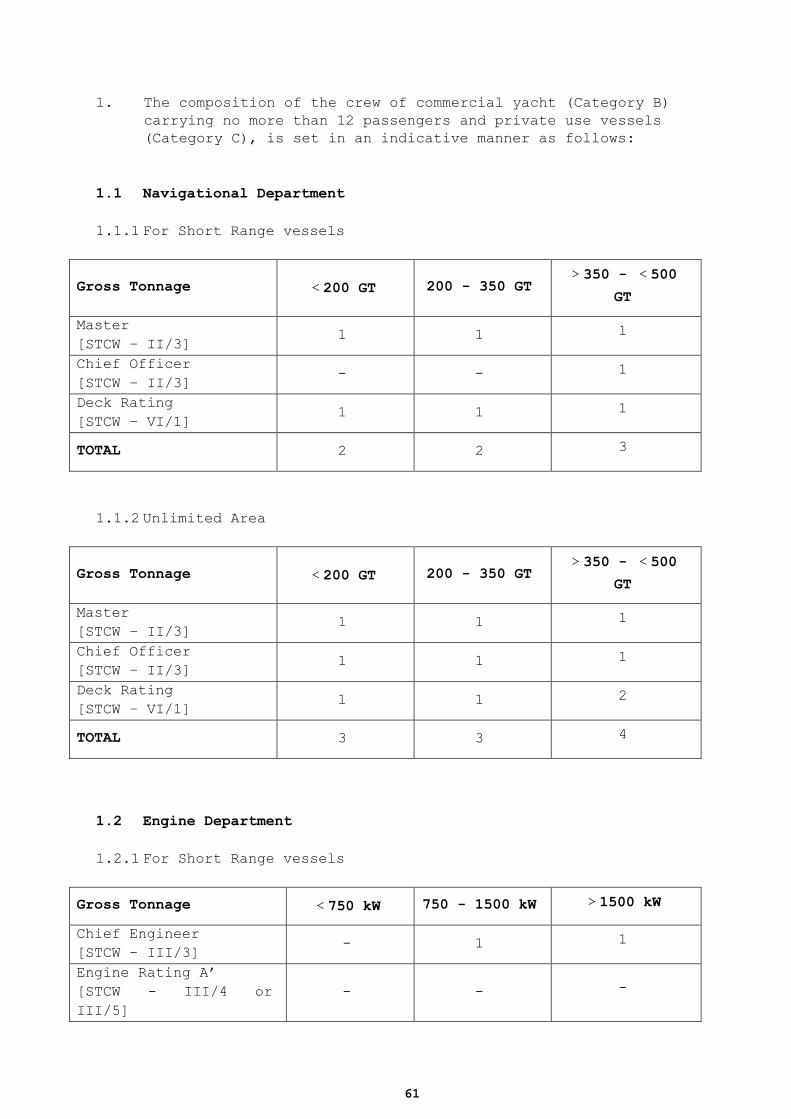
61
1. The composition of the crew of commercial yacht (Category B)
carrying no more than 12 passengers and private use vessels
(Category C), is set in an indicative manner as follows:
1.1 Navigational Department
1.1.1 For Short Range vessels
Gross Tonnage <200 GT 200 - 350 GT >350 - <500
GT
Master
[STCW – II/3] 1 1 1
Chief Officer
[STCW – II/3] - - 1
Deck Rating
[STCW – VI/1] 1 1 1
TOTAL 2 2 3
1.1.2 Unlimited Area
Gross Tonnage <200 GT 200 - 350 GT >350 - <500
GT
Master
[STCW – II/3] 1 1 1
Chief Officer
[STCW – II/3] 1 1 1
Deck Rating
[STCW – VI/1] 1 1 2
TOTAL 3 3 4
1.2 Engine Department
1.2.1 For Short Range vessels
Gross Tonnage <750 kW 750 - 1500 kW >1500 kW
Chief Engineer
[STCW - III/3] - 1 1
Engine Rating A’
[STCW - III/4 or
III/5]
- - -
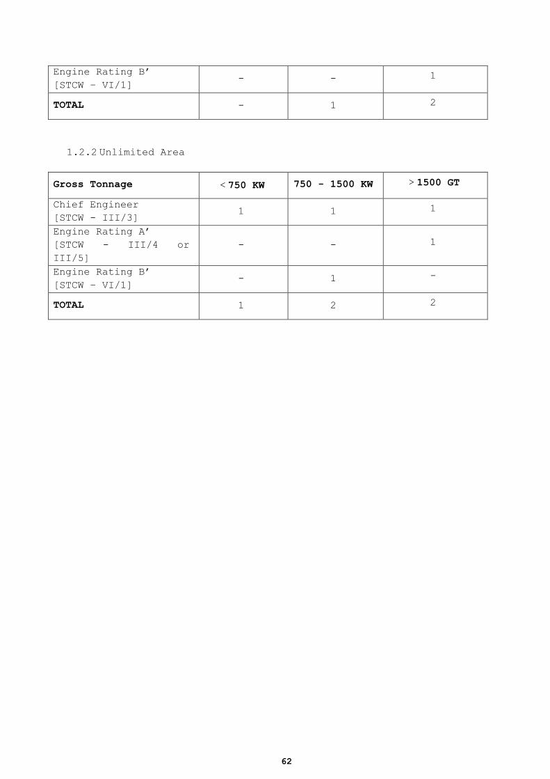
62
Engine Rating B’
[STCW – VI/1] - - 1
TOTAL - 1 2
1.2.2 Unlimited Area
Gross Tonnage <750 KW 750 - 1500 KW >1500 GT
Chief Engineer
[STCW - III/3] 1 1 1
Engine Rating A’
[STCW - III/4 or
III/5]
- - 1
Engine Rating B’
[STCW – VI/1] - 1 -
TOTAL 1 2 2
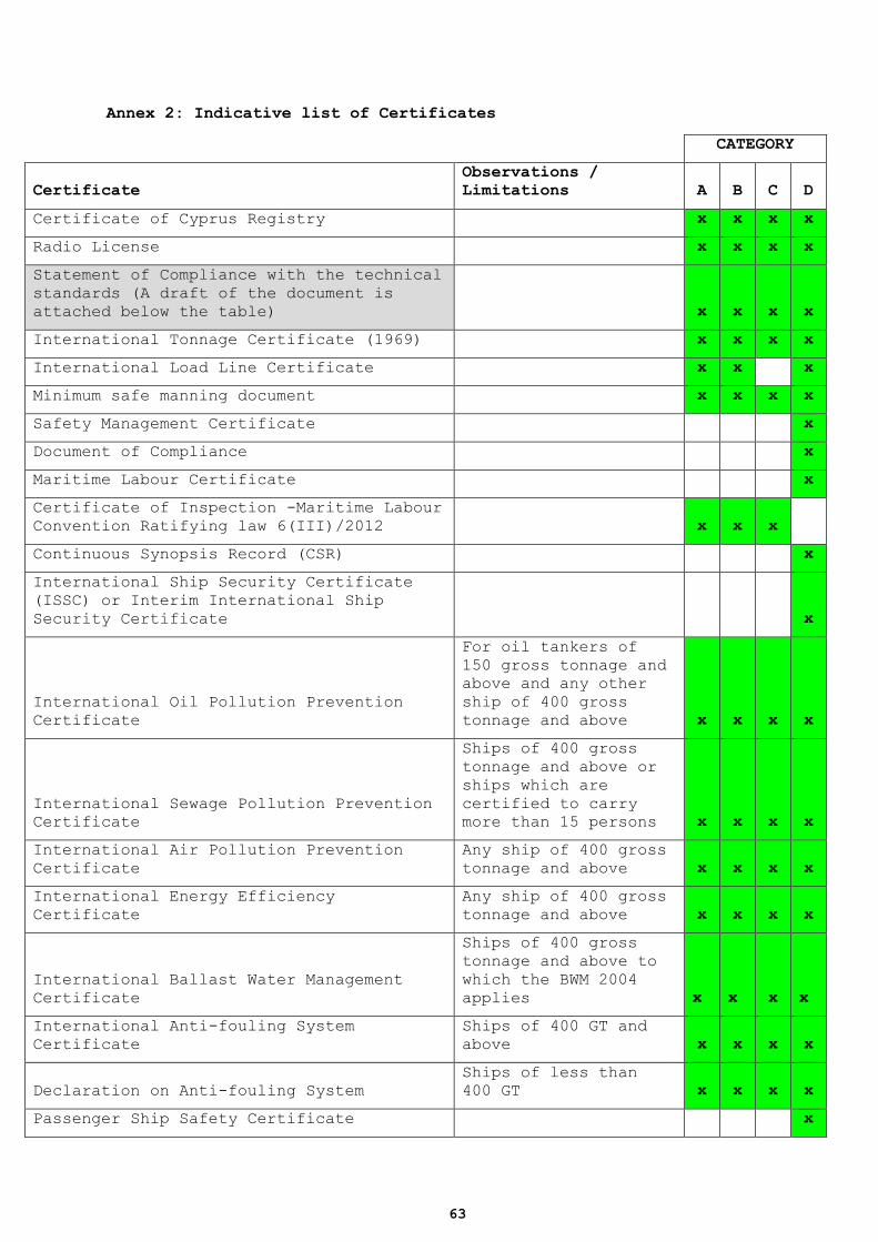
63
Annex 2: Indicative list of Certificates
CATEGORY
Certificate
Observations /
Limitations A B C D
Certificate of Cyprus Registry
x x x x
Radio License
x x x x
Statement of Compliance with the technical
standards (A draft of the document is
attached below the table)
x x x x
International Tonnage Certificate (1969)
x x x x
International Load Line Certificate
x x
x
Minimum safe manning document
x x x x
Safety Management Certificate
x
Document of Compliance
x
Maritime Labour Certificate x
Certificate of Inspection -Maritime Labour
Convention Ratifying law 6(III)/2012 x x x
Continuous Synopsis Record (CSR)
x
International Ship Security Certificate
(ISSC) or Interim International Ship
Security Certificate
x
International Oil Pollution Prevention
Certificate
For oil tankers of
150 gross tonnage and
above and any other
ship of 400 gross
tonnage and above x x x x
International Sewage Pollution Prevention
Certificate
Ships of 400 gross
tonnage and above or
ships which are
certified to carry
more than 15 persons x x x x
International Air Pollution Prevention
Certificate
Any ship of 400 gross
tonnage and above x x x x
International Energy Efficiency
Certificate
Any ship of 400 gross
tonnage and above x x x x
International Ballast Water Management
Certificate
Ships of 400 gross
tonnage and above to
which the BWM 2004
applies x x x x
International Anti-fouling System
Certificate
Ships of 400 GT and
above x x x x
Declaration on Anti-fouling System
Ships of less than
400 GT x x x x
Passenger Ship Safety Certificate
x

64
Certificate of insurance or other
financial security in respect of liability
for the death of and personal injury to
passengers
x
Wreck Removal Certificate
Ships of 300 GT and
above x x x x
Cargo Ship Safety Radio Certificate
Ships of 300 gross
tonnage and over x x
Document of authorization for the carriage
of grain and grain loading manual
Vessels carrying
grain x
International Pollution Prevention
Certificate for the Carriage of Noxious
Liquid Substances in Bulk (NLS
Certificate)
Vessels carrying NLS
cargo x
Certificate of Fitness for the Carriage of
Dangerous Chemicals in Bulk
For chemical tankers
constructed before 1
July 1986 x
International Certificate of Fitness for
the Carriage of Dangerous Chemicals in
Bulk
For chemical
tankers constructed
on or after 1 July
1986 x
International Certificate of Fitness for
the Carriage of Liquefied Gases in Bulk
For Gas Carriers
constructed on or
after 1 July
1986 x
High-Speed Craft Safety Certificate High speed crafts
x
Permit to Operate High-Speed Craft High speed crafts
x
Polar Ship Certificate
Ships operating in
polar waters
x
Diving System Safety Certificate
For structures
carried by vessels,
falling under the
scope of safety of
diving systems code x x
x
Safety Compliance Certificate for
Passenger Submersible Craft
For structures
carried by vessels,
falling under the
scope of
MSC/Circ.981, as
amended by
MSC/Circ.1125 x x
x
Dynamically Supported Craft Construction
and Equipment Certificate
Alternative
certification upon
agreement of the
Administration to
vessels falling under
the provisions of the
relevant code.
x
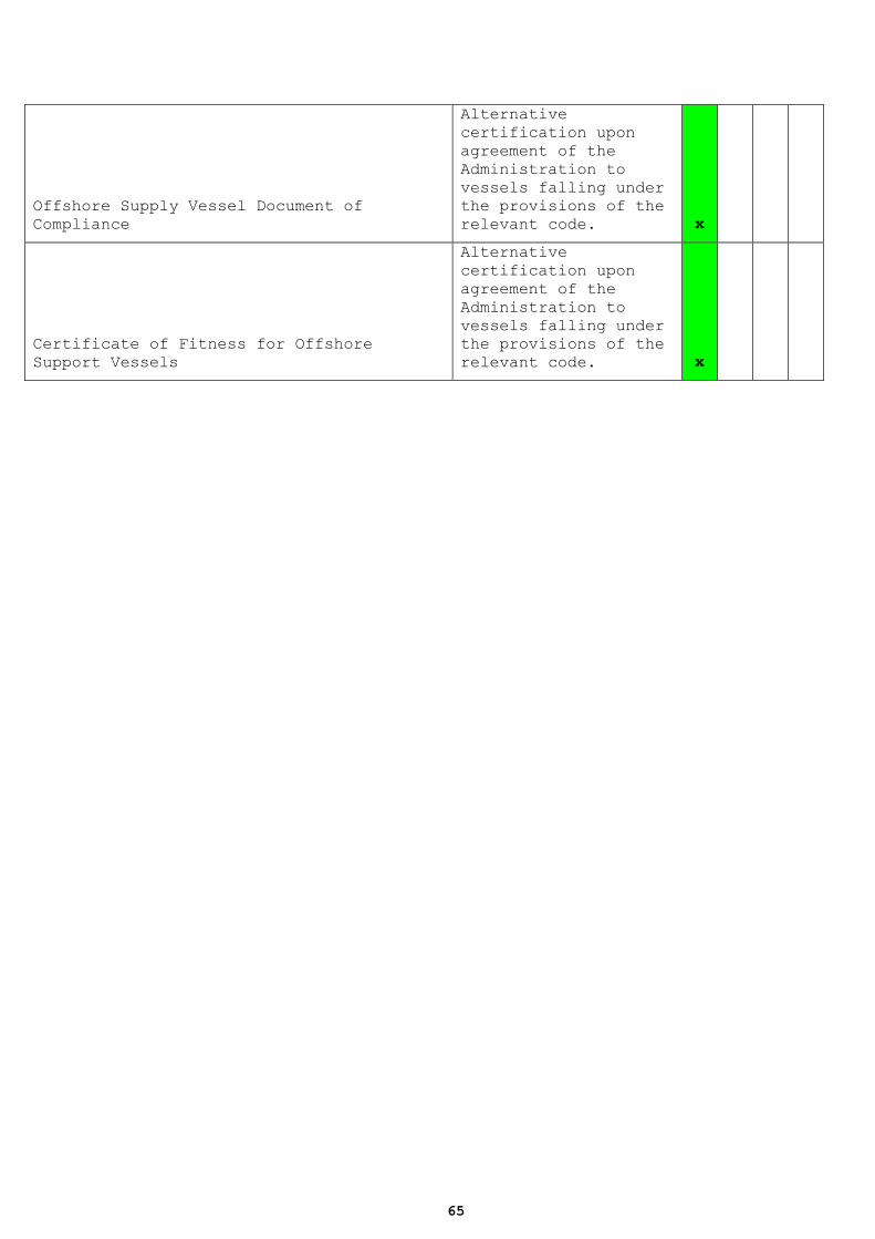
65
Offshore Supply Vessel Document of
Compliance
Alternative
certification upon
agreement of the
Administration to
vessels falling under
the provisions of the
relevant code. x
Certificate of Fitness for Offshore
Support Vessels
Alternative
certification upon
agreement of the
Administration to
vessels falling under
the provisions of the
relevant code. x
66
Annex 3: Conduct in case of maritime accident / incident
A3.1 In case of ‘maritime accident’ or ‘maritime incident’, as defined
in IMO resolution A.849(20) as amended, the owner or the manager or
the Master of a vessel have each one the obligation to inform
immediately the Shipping Deputy Ministry for the maritime accident or
incident.
A3.2 The Marine Accidents Investigation Committee, was established by
virtue of the Marine Casualties and Incidents Investigation Law of
2012 (Law no.94 (I)/2012).
A3.3 The competent Authority evaluates the notifications and decides
whether it will proceed with investigation. In order to decide the
following are taken into account
1. Whether an investigation has been initiated by another
authority such as the Marine Accidents Investigation
Committee
2. The seriousness of the accident or incident
3. The possibility the outcome of the investigation to assist in
the avoidance of similar incident or accident in the future
4. The obligations of the Republic deriving from international
instruments etc.
A3.4 The investigation of maritime accidents and incidents is carried out
by Marine Surveyors of the Shipping Deputy Ministry to the President
who are assigned with such task by the Permanent Secretary of the
Shipping Deputy Ministry.
A3.5 In cases of very serious accidents or / and incidents for the
investigation of which specialized knowledge is required, the
Permanent Secretary of the Shipping Deputy Ministry might assign the
whole or part of the investigation to a specialist with purchase of
services.
A3.6 The investigations carried out in accordance with the provisions of
the present standards are:
6.1. independent of criminal or other parallel investigations held to
determine liability or apportion blame;
A3.7 not unduly precluded, suspended or delayed by reason of such
investigations.
A3.8 Mutatis mutandis, provisions of the ‘Marine Casualties and Incidents
Investigation Law’ of 2012 (Law no.94 (I)/2012), are applied as
follow:
A3.9 Information to be included when notifying the Competent Authority
for a maritime incident or accident – Article 16(2)
A3.10 Authorities of the Investigators – Article 17(1) and 17(2)
A3.11 Confidentiality of Information – Article 19
A3.12 Preservation of Evidence – Article 21(1)
67
A3.13 Investigations carried out as provided in these standards lead to
the publication of a report by the Permanent Secretary.
A3.14 The permanent secretary shall use it best efforts in order the
reports, including the conclusions and possible recommendations, are
available to the public within 12 months from the date of the accident
– incident.
A3.15 In case it is not possible to produce a final report within 12
months from the date of the accident or incident, then an interim
report shall be published.
A3.16 Draft of the report is made known to the persons involved with
the maritime accident or incident, the owner of the vessel as well as
to other involved entities, for their review and comments within a
deadline of one month.
A3.17 The Permanent Secretary, based on a proposal of the investigator,
is making safety recommendations which are made known to persons or
entities to whom they are addressed who shall take them into account.

68
69
Annex 4: Safety Management System - SMS
A4.1. Application /Purpose The purpose of this Annex is to provide assistance to
Companies/owners in developing and implementing an effective safety
management system.
A4.1.1. Safety and Environmental Protection Policy Each company/operator should create a systematic approach to
ensure a safe working environment on board the vessel. A safety
and environmental (S&E) protection policy should be developed.
An S&E policy must address issues of health, safety and the
environment as they affect the company and its staff, both ashore
and on board. Such a policy might read along the following lines:
"The policy of (name of Company/Owner) is to conduct its
activities taking full account of the health and safety of its
employees and of all persons using or connected with the
Company/Owner. In implementing this policy, (name of
Company/Owner) will ensure that the [vessel] is, at all times,
properly maintained and operated by qualified personnel in full
compliance with relevant legislation. In particular the
[Company/Owner] will carry out an assessment of the risks to the
health and safety of workers and others affected by [the
undertaking], and will take the necessary measures to minimise the
risks identified."
A4.1.2. Oil Management Plan The company/owner is urged to develop and implement an oil
management plan and to integrate it with the S&E Policy. This is
not required for vessels over 400GT, for which an IOPP certificate
is required. The Oil Management Plan should be addressed in the
Safety Management Manual (SMM) either as a separate annex or as a
separate document.
A4.1.3. Compliance with rules & regulations (procedure) The company/owner is urged to include in the SMM Plan a procedure
for compliance with all mandatory Rules and Regulations,
applicable to the vessel, such as, the International Regulations
for Preventing Collisions at Sea, Local Navigation Rules such as
within the sea area of the Cyprus Ports Authority, any other
applicable national health and safety regulations and all other
relevant national shipping or guidance notices including Circulars
of the Shipping Deputy Ministry.
A4.1.4. Standard Operation Procedure (SOP) on board (procedure) The company/owner should draw up simple procedures to ensure that
safe working practices are carried out in the operation of the
vessel. These may be in the form of checklists which can be
followed by all personnel. Simple procedures should be developed
for the operation of the vessel. These should include, but not be
limited to:
-testing of equipment (VHF, bilge pumps, life saving appliances,
-fire fighting equipment, emergency alarms, etc);
-testing steering gear, prior to commencing a passage;
-navigation and handling of the vessel;
-maintenance routines;
-bunkering operations;
-watertight/weathertight integrity;
-stability of the vessel;
-conduct of passengers and crew while on board;
70
A4.1.5. Official Log Book Pursuant to section 99 of THE MERCHANT SHIPPING (MASTERS AND
SEAMEN) LAWS OF 1963 TO 2002 an official log-book, an engine room
log-book and a radio log-book, shall be kept in every Cyprus ship,
in the appropriate form for that ship approved by the Minister.
See also P.I. 297/2001 (THE MERCHANT SHIPPING (OFFICIAL LOG BOOKS,
SHIP΄S ARTICLES AND SIX – MONTH LISTS) REGULATIONS OF 2001).
All vessels above 24 meters in Length, are required to carry an
Official Log Book. It might be appropriate that checklists may be
employed by the operator to ensure safe operation and for
navigational items. Such checklists should be recorded within the
Official Log book.
A4.1.6. A4.1.7. Line of Authority and Communication (procedure)
Responsibility and authority of each employee should be clear.
This may be best illustrated in a simple diagram, showing who
reports to whom. This line of authority and reporting should
include the transparent and recorded line of communication between
personnel ashore and on board.
A4.1.8. Reporting accidents (procedure) All Cyprus flag vessels are required to report any accidents and
near accidents to the Administration without any delay whenever
practicable. The company must therefore have a procedure in place
to deal with the mandatory notification in addition to all kept
records and relevant documents in particular the reporting to the
operator/owner, who should implement corrective action, with the
aim of improving safety.
The requirement for reporting accidents should be well understood
by all personnel and in so doing improve the safety culture
practiced on board. Incidents which are subject to national law in
reporting, should be communicated directly and with no undue delay
to the Marine Accident Investigation Committee (www.maic.gov.cy)
and to the Maritime Administration (www.shipping.gov.cy).
A4.1.9. Security Control (procedure) All vessels should include a procedure within their SMS to cope
with the possibility of having at all times adequate control of
access of personnel on board in the event of a security incident.
A4.1.10. Responding to emergency situations (procedure) There should be clearly stated procedures for responding to
emergency situations. Scenarios that should be known to all
personnel should include the following scenarios. The following
list may be expanded by the company/owner based on the evaluation
of other safety related risks and hazards. It is strongly
recommended that checklists are incorporated for training and
familiarisation and implementation purposes.
Fire
Collision
Grounding
Flooding
violent act
main propulsion or steering failure
man overboard
Emergency evacuation
Injured person onboard
A4.1.11. Designated Competent Person (ashore and onboard) There should be at least one designated competent person both
ashore and onboard delegated to take responsibility for health,
71
safety and environmental issues. The designated person should be
clearly identified, competent and trained if required. The
responsibility to comply with the Policy rests with the
owner/operator.
A4.1.12. Drug and Alcohol Policy SMS should include a policy on prevention of alcohol and drug
abuse on board the vessel and on key personnel ashore.
A4.1.13. Safety culture All personnel both ashore and on board have a duty to take care of
themselves and other persons who may be affected by their acts or
omissions. Everyone has the obligation to report incidents
whenever identified or observed to other personnel.
A4.1.14. Communication with Emergency Services It is essential that, in the event of an emergency, there is the
ability to communicate with the emergency services via a shore
base. The shore base may be the company office ashore, the local
Coastguard, Police or Fire Station, or another office as may be
agreed between the vessel and the shore base.
A4.1.15. Master’s responsibility The Master must have authority at all times, to make decisions
with regard to the safety of the vessel and the persons on board.
To ensure that there is no ambiguity regarding the authority of
the Master, there should be a simple written statement to this
effect.
A4.1.16. Training of Personnel All personnel should receive training appropriate to the tasks
they undertake. It is the responsibility of the company/owner to
ensure that this training is given, and that the personnel have an
understanding of the relevant regulations and rules.
A4.1.17. Crew Certificates Master and Crew should be appropriately qualified and certificated
and appropriately trained for their designated duties in
accordance with applicable rules and regulations.
A4.1.18. Crew Familiarisation on board All vessel’s personnel should receive appropriate familiarisation
training and proper instruction in onboard procedures. This
familiarisation training could include among other:
mooring and unmooring;
launching and recovery of survival craft;
evacuation from all areas of the vessel;
Use of Life Saving Appliances;
donning of lifejackets; and
use and handling of fire fighting equipment.
A4.1.19. Emergency Preparedness The potential emergencies likely to be encountered by the vessel
should be considered, as those mentioned in section 12 above, and
drills and exercises should then be carried out at specified
intervals in the handling of these emergencies and evacuation from
the vessel.
Where possible, all personnel, both ashore and on board, should be
involved in these exercises.
The roles and responsibilities of all personnel in an emergency
situation should be defined. A muster list should be prepared and
posted on board where the roles and responsibilities of the Master
and the crew in an emergency situation should be described.
The drills and exercises should be recorded within the Official
Log Book. The names of those who participated should also be
72
recorded.
A4.1.20. Maintenance Program The equipment should be checked and tested daily when in use, in
addition to the tests referred prior to departure or arrival.
There should be procedures for a more detailed and scheduled
inspection and a maintenance programme of the vessel and
equipment. The frequency of the inspections should be determined
by the company/owner taking into account manufacturer’s
recommendations, but every event should be recorded.
An overall maintenance checklist should be employed by crew and
ashore personnel and relevant records should be kept for
the inspection, testing and maintenance of equipment.
A4.1.21. Mandatory Review of the SMS Every company/owner should undertake a review of the safet
y management system of all vessels at least once in five years or
whenever appears to be necessary due to encountered incidents or
non-conformities or whenever the owner/operator or the Master
initiates a review of the system. Records should be kept to
outline any review of the system.
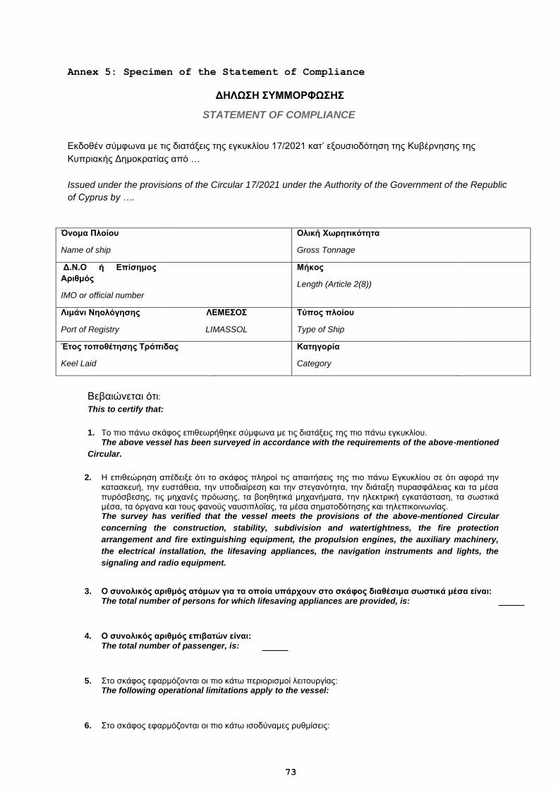
73
Annex 5: Specimen of the Statement of Compliance
ΔΗΛΩΣΗ ΣΥΜΜΟΡΦΩΣΗΣ
STATEMENT OF COMPLIANCE
Eκδοθέν σύμφωνα με τις διατάξεις της εγκυκλίου 17/2021 κατ’ εξουσιοδότηση της Κυβέρνησης της
Κυπριακής Δημοκρατίας από …
Issued under the provisions of the Circular 17/2021 under the Authority of the Government of the Republic
of Cyprus by ….
Όνομα Πλοίου
Name of ship
Ολική Χωρητικότητα
Gross Tonnage
Δ.Ν.Ο ή Επίσημος
Αριθμός
IMO or official number
Μήκος
Length (Article 2(8))
Λιμάνι Νηολόγησης
Port of Registry
ΛΕΜΕΣΟΣ
LIMASSOL
Τύπος πλοίου
Type of Ship
Έτος τοποθέτησης Τρόπιδας
Keel Laid
Κατηγορία
Category
Βεβαιώνεται ότι:
This to certify that:
1. Tο πιο πάνω σκάφος επιθεωρήθηκε σύμφωνα με τις διατάξεις της πιο πάνω εγκυκλίου. The above vessel has been surveyed in accordance with the requirements of the above-mentioned
Circular.
2. H επιθεώρηση απέδειξε ότι το σκάφος πληροί τις απαιτήσεις της πιο πάνω Εγκυκλίου σε ότι αφορά την κατασκευή, την ευστάθεια, την υποδιαίρεση και την στεγανότητα, την διάταξη πυρασφάλειας και τα μέσα πυρόσβεσης, τις μηχανές πρόωσης, τα βοηθητικά μηχανήματα, την ηλεκτρική εγκατάσταση, τα σωστικά μέσα, τα όργανα και τους φανούς ναυσιπλοΐας, τα μέσα σηματοδότησης και τηλεπικοινωνίας. The survey has verified that the vessel meets the provisions of the above-mentioned Circular
concerning the construction, stability, subdivision and watertightness, the fire protection
arrangement and fire extinguishing equipment, the propulsion engines, the auxiliary machinery,
the electrical installation, the lifesaving appliances, the navigation instruments and lights, the
signaling and radio equipment.
3. Ο συνολικός αριθμός ατόμων για τα οποία υπάρχουν στο σκάφος διαθέσιμα σωστικά μέσα είναι: The total number of persons for which lifesaving appliances are provided, is:
4. Ο συνολικός αριθμός επιβατών είναι: The total number of passenger, is:
5. Στο σκάφος εφαρμόζονται οι πιο κάτω περιορισμοί λειτουργίας: The following operational limitations apply to the vessel:
6. Στο σκάφος εφαρμόζονται οι πιο κάτω ισοδύναμες ρυθμίσεις:
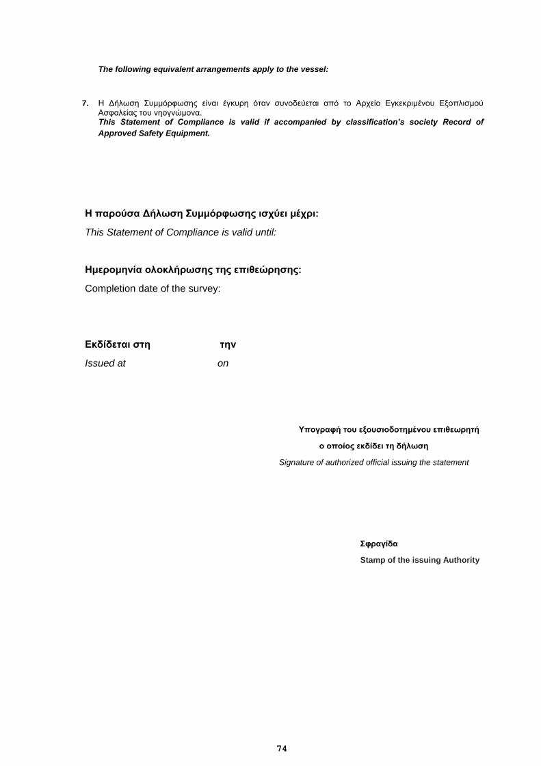
74
The following equivalent arrangements apply to the vessel:
7. Η Δήλωση Συμμόρφωσης είναι έγκυρη όταν συνοδεύεται από το Αρχείο Εγκεκριμένου Εξοπλισμού Ασφαλείας του νηογνώμονα. This Statement of Compliance is valid if accompanied by classification’s society Record of
Approved Safety Equipment.
Η παρούσα Δήλωση Συμμόρφωσης ισχύει μέχρι:
This Statement of Compliance is valid until:
Ημερομηνία ολοκλήρωσης της επιθεώρησης:
Completion date of the survey:
Εκδίδεται στη την
Issued at on
Υπογραφή του εξουσιοδοτημένου επιθεωρητή
ο οποίος εκδίδει τη δήλωση
Signature of authorized official issuing the statement
Σφραγίδα
Stamp of the issuing Authority
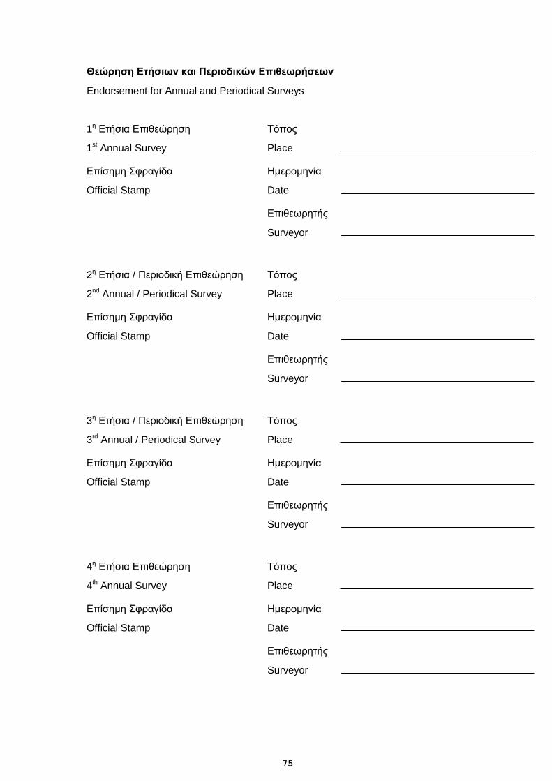
75
Θεώρηση Ετήσιων και Περιοδικών Επιθεωρήσεων
Endorsement for Annual and Periodical Surveys
1η Ετήσια Επιθεώρηση Τόπος
1st Annual Survey Place
Επίσημη Σφραγίδα Ημερομηνία
Official Stamp Date
Επιθεωρητής
Surveyor
2η Ετήσια / Περιοδική Επιθεώρηση Τόπος
2nd Annual / Periodical Survey Place
Επίσημη Σφραγίδα Ημερομηνία
Official Stamp Date
Επιθεωρητής
Surveyor
3η Ετήσια / Περιοδική Επιθεώρηση Τόπος
3rd Annual / Periodical Survey Place
Επίσημη Σφραγίδα Ημερομηνία
Official Stamp Date
Επιθεωρητής
Surveyor
4η Ετήσια Επιθεώρηση Τόπος
4th Annual Survey Place
Επίσημη Σφραγίδα Ημερομηνία
Official Stamp Date
Επιθεωρητής
Surveyor
76
Electronic file with a
specimen of the Statement of
Compliance with the present
standards
Microsoft Word 97 - 2003 Document