Shielding Performance and Measurement Method of High- Voltage Wiring … · · 2015-01-30EVS28...
8
EVS28 International Electric Vehicle Symposium and Exhibition 1 EVS28 KINTEX, Korea, May 3-6, 2015 Shielding Performance and Measurement Method of High- Voltage Wiring Harnesses Yoshio Mizutani 1 , Akihiro Hayashi 1 , Hiroyuki Kodama 2 , Hirokazu Koseki 2 1 Hybrid Vehicle R&D Div., AutoNetworks Technologies, Ltd. (Sumitomo Electric Group), 1-14 Nishisuehiro-cho, Yokkaichi, Mie 510-8503 Japan, [email protected] 2 SEI ANTech-Europe GmbH (Sumitomo Electric Group), Brandgehaege 11, D-38444 Wolfsburg-Hattorf, Germany, [email protected] Abstract High-voltage and large-current are applied to a high-voltage wiring harness of HEVs (Hybrid Electric Vehicles), PHEVs (Plug-in Hybrid Electric Vehicles) and EVs (Electric Vehicles). Ensuring the compatibility with the generally used 12 V system is important to avoid electro-magnetic compatibility problems, and thus, the development of shielding technology for the high-voltage wiring harnesses is essential. Clearly, a measurement method of the shielding performance is necessary for the shielding technology development of high-voltage wiring harnesses. We have two methods for the measurement of shielding performance, one is the current probe method based on the international specification CISPR25, and the other is the transfer impedance method mainly used in Europe. In this paper, firstly the shielding concept and the shielding structure of high-voltage wiring harness, measurement method of shielding performance are introduced. These measurement methods are compared by using shielded wires and high-voltage wiring harnesses that consist of shielded wires and connectors. The comparison results show the good correlation between both measurement methods. Then the theoretical calculation and the sensitivity of these measurement methods are discussed. The comparison result of various shielding structure also showed that the aluminium pipe shielding structure which our company developed has excellent shielding performance. Keywords: high-voltage wiring harness, electro-magnetic shielding, transfer impedance method, current probe methods 1 Introduction HEVs, PHEVs and EVs that enable reductions in fuel consumptions and CO 2 emissions are highly interesting from the viewpoint of the global environment. In these vehicles, a high-voltage circuit is necessary for motor driving and energy regenerating, in addition to a conventional 12V system. Sumitomo Electric Group develops and manufactures high-voltage wiring harnesses that correspond to these kinds of components [1]-[4]. Especially for the high-voltage wiring harnesses, it is important to include excellent electro- magnetic shielding compatible with sensitive devices, such as the radio control system and high speed communication system. Clearly, a measurement method of the shielding performance is necessary for shielding technology
Transcript of Shielding Performance and Measurement Method of High- Voltage Wiring … · · 2015-01-30EVS28...
EVS28 International Electric Vehicle Symposium and Exhibition 1
EVS28 KINTEX, Korea, May 3-6, 2015
Shielding Performance and Measurement Method of High-Voltage Wiring Harnesses
Yoshio Mizutani1, Akihiro Hayashi1, Hiroyuki Kodama2, Hirokazu Koseki2
1Hybrid Vehicle R&D Div., AutoNetworks Technologies, Ltd. (Sumitomo Electric Group), 1-14 Nishisuehiro-cho, Yokkaichi, Mie 510-8503 Japan, [email protected]
2SEI ANTech-Europe GmbH (Sumitomo Electric Group), Brandgehaege 11, D-38444 Wolfsburg-Hattorf, Germany, [email protected]
Abstract
High-voltage and large-current are applied to a high-voltage wiring harness of HEVs (Hybrid Electric
Vehicles), PHEVs (Plug-in Hybrid Electric Vehicles) and EVs (Electric Vehicles). Ensuring the
compatibility with the generally used 12 V system is important to avoid electro-magnetic compatibility
problems, and thus, the development of shielding technology for the high-voltage wiring harnesses is
essential. Clearly, a measurement method of the shielding performance is necessary for the shielding
technology development of high-voltage wiring harnesses. We have two methods for the measurement of
shielding performance, one is the current probe method based on the international specification CISPR25,
and the other is the transfer impedance method mainly used in Europe.
In this paper, firstly the shielding concept and the shielding structure of high-voltage wiring harness,
measurement method of shielding performance are introduced. These measurement methods are compared
by using shielded wires and high-voltage wiring harnesses that consist of shielded wires and connectors.
The comparison results show the good correlation between both measurement methods. Then the
theoretical calculation and the sensitivity of these measurement methods are discussed. The comparison
result of various shielding structure also showed that the aluminium pipe shielding structure which our
company developed has excellent shielding performance.
Keywords: high-voltage wiring harness, electro-magnetic shielding, transfer impedance method, current probe methods
1 Introduction HEVs, PHEVs and EVs that enable reductions in fuel consumptions and CO2 emissions are highly interesting from the viewpoint of the global environment. In these vehicles, a high-voltage circuit is necessary for motor driving and energy regenerating, in addition to a conventional 12V system. Sumitomo Electric Group develops and
manufactures high-voltage wiring harnesses that correspond to these kinds of components [1]-[4]. Especially for the high-voltage wiring harnesses, it is important to include excellent electro-magnetic shielding compatible with sensitive devices, such as the radio control system and high speed communication system. Clearly, a measurement method of the shielding performance is necessary for shielding technology
EVS28 International Electric Vehicle Symposium and Exhibition 2
development of high-voltage wiring harnesses. We compared typical two measurement methods using shielded wires and high-voltage wiring harnesses.
2 Shielding Concept of High-Voltage Wiring Harness
One of the key requirements for high-voltage wiring harnesses is its sheath performance. The main requirements of the sheath performance are the shielding and the mechanical protection. The shielding is required due to the electro-magnetic field which is created by the high-voltage and large-current flowing through the high-voltage wiring harness. Additionally, the power electronics also generate some high-frequency noises, which can be also induced into the high-voltage wiring harness. Therefore, the shielding acts mainly as an EMI (Electro-Magnetic Interference) shielding to avoid any electro-magnetic influence to the low-voltage wiring harness applications like the radio or other high-frequency systems inside the vehicle. To prevent a close proximity to the low-voltage wiring harness, the high-voltage wiring harness is routed mainly under the floor of the vehicle using the vehicle body as an additional EMI shielding. Due to this under-floor routing of the high-voltage wiring harness, a mechanical protection is also required to avoid any wire damage by chipping stones or accidents [3].
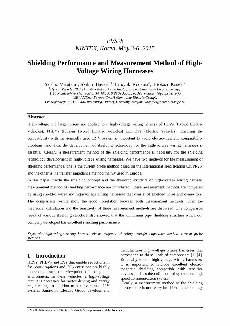
2.1 Kind of Shielding Structure There are mainly two kinds of shielding structures for high-voltage wiring harnesses, an individual shielding structure and a bundle shielding structure. Figure 1 shows the shielding structure of the high-voltage wiring harness manufactured in our company. The bundle braided shielding structure and the aluminium pipe shielding structure are categorized into the bundle shielding structure. The individual shielding, a structure that separately shields each wire, is the most conventional structure for the high-voltage wiring harness. The bundle shielding is a structure that has a common shielding layer and shields all wires together by the shielding layer. The bundle braided shielding structure has a shielding layer made with braided metal wire. The bundle braided shielding structure was first applied for the high-voltage wiring harness of HEVs by our company in 2003 [2]. Furthermore, the aluminum pipe shielding was developed and applied to HEVs by
our company for the first time in the world in 2005 [1]. The aluminum pipe shielding structure uses an aluminum pipe as the material of the shielding layer. Therefore not only the shielding performance but also mechanical protection and heat shielding are good [3],[4].
Figure 1: Shielding structures
3 Measurement Method of Shielding Performance
We use two measurement methods of shielding performance for the high-voltage wiring harness. One is the current probe method, the other is the transfer impedance method. The former is a typical ‘indirect-method’ for the shielding performance. This is a method in which when signal is input into an internal conductor of a sample, radiated noises penetrating through the shielding layer are detected by devices such as sensors or antennas. On the other hand, the latter is a typical ‘direct-method’ for the shielding performance. With this method the coupling state between an internal conductor and a shielding layer of a sample is directly observed by measuring the voltage of the internal conductor induced by the current flowing through the shielding layer. Japanese and European automakers typically prefer the former and latter methods, respectively. This section explains the both measurement methods.
3.1 Current probe method This measurement method is based on the international specification CISPR25 for the shielding performance of components within the
EVS28 International Electric Vehicle Symposium and Exhibition 3
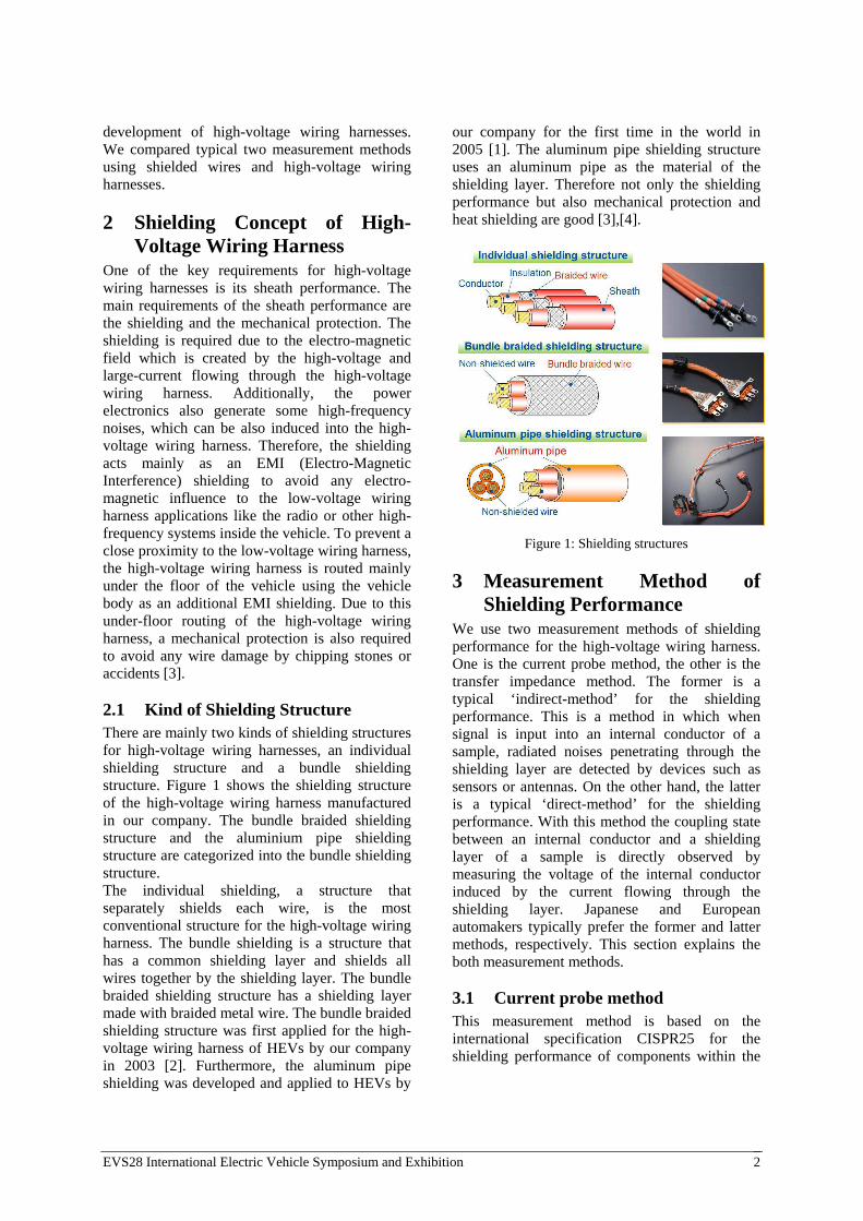
automobile field. Our company is, thus, quite familiar with this measurement method. Figure 2 shows the measurement system using a spectrum analyzer with a built-in tracking generator and a current probe. In order to avoid influence of external electro-magnetic disturbances, the whole measurement system is placed inside a shielded room. Two kinds of probe are applied depending on the frequency to pick up the noise radiated from samples. This measurement is operated on a copper plate for the purpose of securing a common and stable ground of the whole measurement system.
Figure 2: Measurement system for the current probe method
The principle of the measurement is that the current probe senses the radiated noise penetrating through the shielding layer when the input signal comes from the spectrum analyzer to the internal conductor of a sample through the connection box. The measurement parameter in this measurement method is the power ratio of the input signal and output signal, and is calculated according to the following equation.
= 10 log
(1)
Then the shielding performance is calculated as the difference between the shielded and non-shielded samples. With this system various types of samples such as shielded wires without connectors and wiring harnesses that have connectors jointed to the wires can be measured by applying the particular connector-interface adaptors.
3.2 Transfer impedance method This measurement method is standardized by the international specification IEC61196-1 for a coaxial cable testing, which is a method to test the shielding performance of components within the automobile field and commonly used in Europe. Our company have begun to apply this
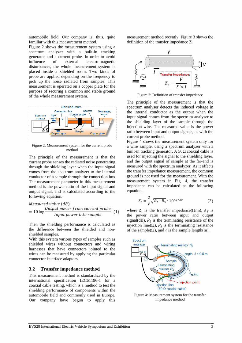
measurement method recently. Figure 3 shows the definition of the transfer impedance Zt.
Figure 3: Definition of transfer impedance
The principle of the measurement is that the spectrum analyser detects the induced voltage in the internal conductor as the output when the input signal comes from the spectrum analyser to the shielding layer of the sample through the injection wire. The measured value is the power ratio between input and output signals, as with the current probe method. Figure 4 shows the measurement system only for a wire sample, using a spectrum analyzer with a built-in tracking generator. A 50Ω coaxial cable is used for injecting the signal to the shielding layer, and the output signal of sample at the far-end is measured with the spectrum analyzer. As it affects the transfer impedance measurement, the common ground is not used for the measurement. With the measurement system in Fig. 4, the transfer impedance can be calculated as the following equation.
=2
ℓ ∙ ∙ 10
⁄ (2)
where is the transfer impedance(Ω/m), is the power ratio between input and output signal(dB), is the terminating resistance of the injection line(Ω), is the terminating resistance of the sample(Ω), and ℓ is the sample length(m).
Figure 4: Measurement system for the transfer
impedance method
EVS28 International Electric Vehicle Symposium and Exhibition 4
The transfer impedance method as shown in Fig. 4 was originally developed for measuring the shielding performance of shielded wires without connectors, and did not consider wiring harness samples with connectors including the high-voltage wiring harness. Therefore, we modified the measurement system explained above to measure wiring harnesses correctly. Figure 5 shows the measurement system that was modified based on Fig. 4 in order to measure wiring harnesses. The position of the injection point has been changed onto the connection box from on the wire in order to consider the influence of connectors at both ends of the shielded wire. Due to this modification, the input signal flows through the shielding shell that is the shielding layer for the connector, thereby making it possible to measure the shielding performance of the whole wiring harness, including connectors. The transfer impedance can be calculated like Fig. 4 by Eq. (2).
Figure 5: Transfer impedance method for wiring harness
4 Comparison of the Current Probe Method and the Transfer Impedance Method
As previously described, the current probe method is well proven among Japanese automakers, and also well established in our company. However, not much knowledge is available with respect to the transfer impedance method, because it has not been long since the beginning of using this measurement system for high-voltage wiring harnesses. Therefore, it was necessary to carefully verify the accuracy of the measurement values and the correlativity between the both measurement methods. In this section, the measurement values of both measurement methods were compared and verified using various samples as follows.
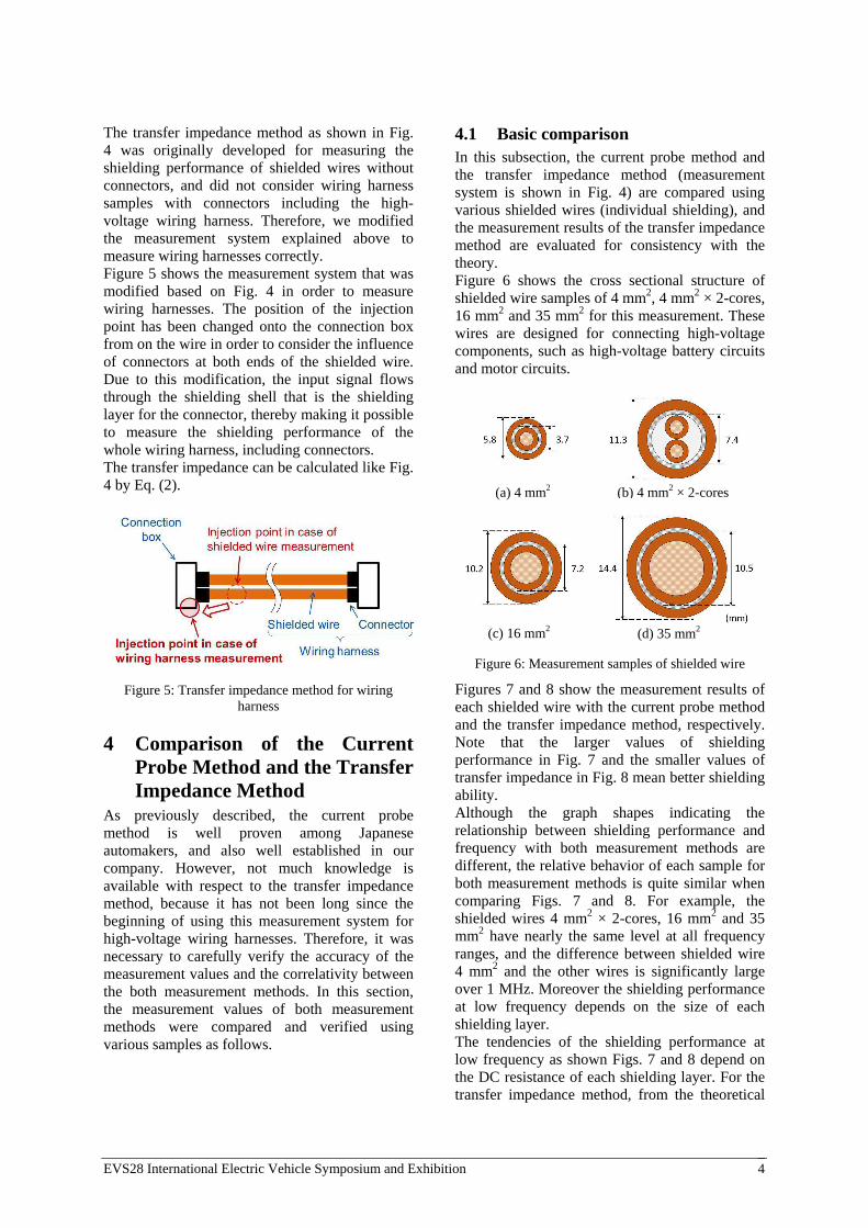
4.1 Basic comparison In this subsection, the current probe method and the transfer impedance method (measurement system is shown in Fig. 4) are compared using various shielded wires (individual shielding), and the measurement results of the transfer impedance method are evaluated for consistency with the theory. Figure 6 shows the cross sectional structure of shielded wire samples of 4 mm2, 4 mm2 × 2-cores, 16 mm2 and 35 mm2 for this measurement. These wires are designed for connecting high-voltage components, such as high-voltage battery circuits and motor circuits.
Figure 6: Measurement samples of shielded wire
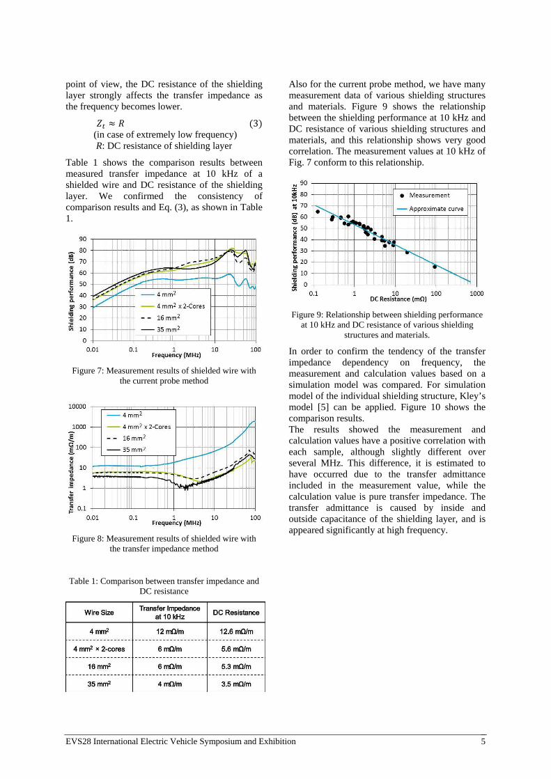
Figures 7 and 8 show the measurement results of each shielded wire with the current probe method and the transfer impedance method, respectively. Note that the larger values of shielding performance in Fig. 7 and the smaller values of transfer impedance in Fig. 8 mean better shielding ability. Although the graph shapes indicating the relationship between shielding performance and frequency with both measurement methods are different, the relative behavior of each sample for both measurement methods is quite similar when comparing Figs. 7 and 8. For example, the shielded wires 4 mm2 × 2-cores, 16 mm2 and 35 mm2 have nearly the same level at all frequency ranges, and the difference between shielded wire 4 mm2 and the other wires is significantly large over 1 MHz. Moreover the shielding performance at low frequency depends on the size of each shielding layer. The tendencies of the shielding performance at low frequency as shown Figs. 7 and 8 depend on the DC resistance of each shielding layer. For the transfer impedance method, from the theoretical
(b) 4 mm2 × 2-cores
(d) 35 mm2
(a) 4 mm2
(c) 16 mm2
EVS28 International Electric Vehicle Symposium and Exhibition 5
point of view, the DC resistance of the shielding layer strongly affects the transfer impedance as the frequency becomes lower.
≈ (3) (in case of extremely low frequency) R: DC resistance of shielding layer
Table 1 shows the comparison results between measured transfer impedance at 10 kHz of a shielded wire and DC resistance of the shielding layer. We confirmed the consistency of comparison results and Eq. (3), as shown in Table 1.
Figure 7: Measurement results of shielded wire with the current probe method
Figure 8: Measurement results of shielded wire with the transfer impedance method
Table 1: Comparison between transfer impedance and DC resistance
Also for the current probe method, we have many measurement data of various shielding structures and materials. Figure 9 shows the relationship between the shielding performance at 10 kHz and DC resistance of various shielding structures and materials, and this relationship shows very good correlation. The measurement values at 10 kHz of Fig. 7 conform to this relationship.
Figure 9: Relationship between shielding performance at 10 kHz and DC resistance of various shielding
structures and materials.
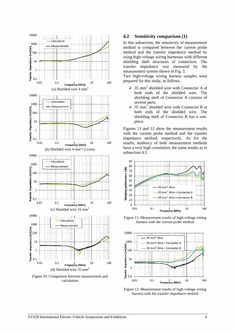
In order to confirm the tendency of the transfer impedance dependency on frequency, the measurement and calculation values based on a simulation model was compared. For simulation model of the individual shielding structure, Kley’s model [5] can be applied. Figure 10 shows the comparison results. The results showed the measurement and calculation values have a positive correlation with each sample, although slightly different over several MHz. This difference, it is estimated to have occurred due to the transfer admittance included in the measurement value, while the calculation value is pure transfer impedance. The transfer admittance is caused by inside and outside capacitance of the shielding layer, and is appeared significantly at high frequency.
EVS28 International Electric Vehicle Symposium and Exhibition 6
(a) Shielded wire 4 mm2
(b) Shielded wire 4 mm2×2-cores
(c) Shielded wire 16 mm2
(d) Shielded wire 35 mm2
Figure 10: Comparison between measurement and calculation
4.2 Sensitivity comparison (1) In this subsection, the sensitivity of measurement method is compared between the current probe method and the transfer impedance method by using high-voltage wiring harnesses with different shielding shell structures of connectors. The transfer impedance was measured by the measurement system shown in Fig. 5. Two high-voltage wiring harness samples were prepared for this study, as follows.
35 mm2 shielded wire with Connector A at both ends of the shielded wire. The shielding shell of Connector A consists of several parts. 35 mm2 shielded wire with Connector B at
both ends of the shielded wire. The shielding shell of Connector B has a one-piece.
Figures 11 and 12 show the measurement results with the current probe method and the transfer impedance method, respectively. As for the results, tendency of both measurement methods have a very high correlation, the same results as in subsection 4.1.
Figure 11: Measurement results of high-voltage wiring harness with the current probe method
Figure 12: Measurement results of high-voltage wiring harness with the transfer impedance method
EVS28 International Electric Vehicle Symposium and Exhibition 7
Under 1 MHz, there is no remarkable difference among all the samples. On the other hand, the high-voltage wiring harnesses have worse performance compared to the shielded wire sample over 1 MHz. These tendencies were confirmed from results of both measurement methods. Possible reasons for this tendency are as follows: Under 1 MHz, the contact between the shielding layer of the shielded wire and the shielding shell of the connector has very low resistance. Over 1 MHz, it is estimated that the noise is radiated from the shielding shell. In comparison of two connector types, Connector B is slightly better than Connector A due to the difference of shielding shell structure. In Connector A with the shielding shell consisting of several parts, the connection between these parts of the shielding shell is estimated to negatively affect the shielding performance. Both measurement methods can sense even this small difference of each connector. We confirmed that the transfer impedance method is capable of making a measurement while considering the influence of connectors, as the current probe method is.
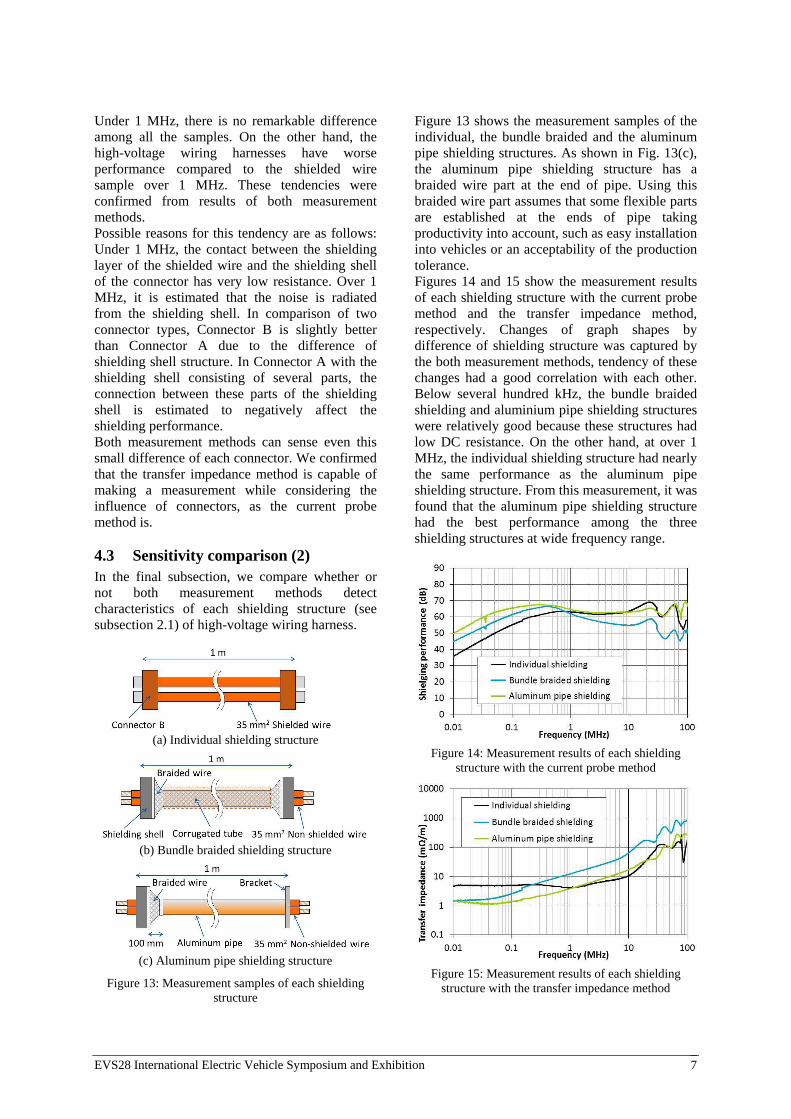
4.3 Sensitivity comparison (2) In the final subsection, we compare whether or not both measurement methods detect characteristics of each shielding structure (see subsection 2.1) of high-voltage wiring harness.
(a) Individual shielding structure
(b) Bundle braided shielding structure
(c) Aluminum pipe shielding structure
Figure 13: Measurement samples of each shielding structure
Figure 13 shows the measurement samples of the individual, the bundle braided and the aluminum pipe shielding structures. As shown in Fig. 13(c), the aluminum pipe shielding structure has a braided wire part at the end of pipe. Using this braided wire part assumes that some flexible parts are established at the ends of pipe taking productivity into account, such as easy installation into vehicles or an acceptability of the production tolerance. Figures 14 and 15 show the measurement results of each shielding structure with the current probe method and the transfer impedance method, respectively. Changes of graph shapes by difference of shielding structure was captured by the both measurement methods, tendency of these changes had a good correlation with each other. Below several hundred kHz, the bundle braided shielding and aluminium pipe shielding structures were relatively good because these structures had low DC resistance. On the other hand, at over 1 MHz, the individual shielding structure had nearly the same performance as the aluminum pipe shielding structure. From this measurement, it was found that the aluminum pipe shielding structure had the best performance among the three shielding structures at wide frequency range.
Figure 14: Measurement results of each shielding
structure with the current probe method
Figure 15: Measurement results of each shielding
structure with the transfer impedance method
EVS28 International Electric Vehicle Symposium and Exhibition 8
In general, shielding performance at low frequency range was strongly affected by the DC resistance as explained in subsection 4.1, it was confirmed on Figs. 14 and 15, too. At higher frequency, however, as the frequency moved higher a high surface density structure of the shielding layer, namely the shielding layer structure that covers the wire surface without aperture, was advantageous for shielding performance. The results of both measurement methods proved that the aluminum pipe shielding structure with low DC resistance and without aperture is suitable for both these frequency ranges.
5 Conclusion The comparison results between the current
probe method and the transfer impedance method indicated a good correlation for the shielding performance of shielded wires and high-voltage wiring harnesses. The sensitivity of both measurement methods
for different connectors or shielding structures was comparable. The aluminum pipe shielding structure had the
best shielding performance among the three shielding types for high-voltage wiring harnesses.
Acknowledgments We would like to thank Dr. Thomas Flottmann, Mr. Marcin Zwolinski and Mr. Ole Adam in Sumitomo Electric Bordnetze GmbH for kindly supporting to guide the measurements and to prepare the samples at our development center in Wolfsburg, Germany.
References [1] High-Voltage Wiring Harness Employed in New
Model Hybrid Vehicle, SEI WORLD 340(2006).
[2] S. Miyazaki, S. Kihira, T. Nozaki, New Shielding Construction of High-Voltage Wiring Harnesses for Toyota Prius –Winning of Toyota Superior Award for Cost Reduction-, SEI Technical Review, no. 61(January 2006), 21-23.
[3] Y. Mizutani, O. Weiss, Pipe Shield High-Voltage Wiring Harness, 26th International Electric Vehicle Symposium, Los Angeles, California, May 2012.
[4] Y. Itani, Y. Mizutani, M. Kuwahara, S. Hashimoto, Aluminum Pipe Shielded High-Voltage Wiring Harness, SEI Technical Review, no. 79(October 2014), 18-21.
[5] T. Kley, Optimized Single-Braided Cable Shields, IEEE Trans. Electromagn. Compat., vol. EMC-35, no. 1(February 1993).
Authors
Yoshio Mizutani received a master’s degree in electrical engineering from Nagaoka University of Technology in 1991. He joined Sumitomo Electric Industries, Ltd. in 1991, where he worked at power cable division. He has been moved to AutoNetworks Technologies, Ltd. in 2000, and since then he has been in charge of R&D for high-voltage wiring harnesses.
Akihiro Hayashi received a bachelor’s degree in chemical engineering from Osaka University in 1988. He joined Sumitomo Electric Industries, Ltd. in 1988, where he worked at magnet wire division. He has been moved to AutoNetworks Technologies, Ltd. in 2009, and since then he has been in charge of R&D for high-voltage wiring harnesses.
Hiroyuki Kodama received a master’s degree in semiconductor device engineering from Hiroshima University in 2003. He joined Sumitomo Wiring Systems, Ltd. in 2003. He has been moved to SEI ANTech-Europe GmbH in 2013, and is responsible for the development of high-voltage wiring harnesses.
Hirokazu Koseki received a master’s degree in precise mechanical engineer from Utsunomiya University in 1989. He joined Sumitomo Electric Industries, Ltd. in 1989. After working in UK and Hungary as electric wire engineer, from 2006 he has moved to AntoNetworks Technologies, Ltd. in Japan. Since 2010 he is General Manager of high- voltage wiring harnesses and components R&D at SEI ANTech-Europe GmbH.