seminar bwb
41
AERODYNAMIC DESIGN EVALUATION OF BLENDED WING BODY DESIGN IN AIRCRAFTS AND ITS SCOPE IN COMMERCIAL USE A Seminar Report submitted in partial fulfillment of the requirements for the award of BACHELOR OF TECHNOLOGY IN MECHANICAL ENGINEERING Under University of Calicut By ANOOP M R APAMEME008 DEPARTMENT OF MECHANICAL ENGINEERING Aryanet Institute of Technology Velikkad, Mundur, Palakkad- 678592 MARCH 2016
Transcript of seminar bwb
AERODYNAMIC DESIGN EVALUATION OF BLENDED WING
BODY DESIGN IN AIRCRAFTS AND ITS SCOPE IN
COMMERCIAL USE
A Seminar Report submitted in partial fulfillment of the requirements for the award of
BACHELOR OF TECHNOLOGY
IN
MECHANICAL ENGINEERING
Under University of Calicut
By
ANOOP M R
APAMEME008
DEPARTMENT OF MECHANICAL ENGINEERING
Aryanet Institute of Technology
Velikkad, Mundur, Palakkad- 678592
MARCH 2016
DEPARTMENT OF MECHANICAL ENGINEERING ARYANET INSTITUTE OF TECHNOLOGY
VELIKKAD, PALAKKAD, PIN 678 592
CERTIFICATE
Certified that the seminar titled AERODYNAMIC DESIGN
EVALUATION OF BLENDED WING BODY DESIGN IN
AIRCRAFTS AND ITS SCOPE IN COMMERCIAL USE is a bonafide
record of the work done by ANOOP M R (APAMEME008) under my
supervision and guidance, and is submitted in March 2016 in partial
fulfillment of the requirements for award of the Degree of Bachelor of
Technology in Mechanical Engineering under University of Calicut.
Seminar Guide Head of the Department
SREEJITH M Prof. V Gopinathan
Assistant professor Department of Mechanical
Department of Mechanical Engineering.
Engineering.
Place : PALAKKAD
Date :
Seminar report BWB Analysis
_____________________________________________________________________
Department of Mechanical Engineering, AIT (2012-2016)
ii
ACKNOWLEDGEMENT
While bringing out this seminar to its final form, I came across a number of
people whose contributions in various ways helped my field of research and they
deserve special thanks. It is a pleasure to convey my gratitude to all of them.
I would like to express my deepest gratitude to Dr. M.R. VIKRAMAN,
Principal, Aryanet Institute of Technology, Palakkad for fostering an excellent
academic climate in the college and for his support and encouragement throughout the
course period.
I wish to thank Prof. V GOPINATHAN, Head of the Department,
Mechanical Engineering, Aryanet Institute of Technology, Palakkad, for providing all
the facilities and support for execution of the work.
I am thankful to Mr. SREEJITH M (Seminar Coordinator and Seminar
Guide), Assistant Professor, Department of Mechanical Engineering, Aryanet Institute
of Technology, Palakkad for his advice, encouragement, suggestions, invaluable
supervision and support throughout this seminar work.
I would like to take this opportunity to thank my friends who spent their
valuable time and shared their knowledge for helping me to complete the seminar
with the best possible result.
ANOOP M R
Seminar report BWB Analysis
_____________________________________________________________________
Department of Mechanical Engineering, AIT (2012-2016)
iii
ABSTRACT
The desire to produce environment friendly aircraft that is aerodynamically
efficient and capable of conveying large number of passengers over long range at
reduced operating cost led aircraft designers to develop the Blended Wing Body
(BWB) aircraft concept. The BWB aircraft represents a paradigm shift in the design
of aircraft. The design provides aerodynamic and environmental benefits and is
suitable for the integration of advanced systems and concepts like laminar flow
technology, jet flap and distributed propulsion. However despite these benefits BWB
aircraft design is yet to be developed for commercial air transport due to several
challenges. The emerging trends in BWB aircraft design highlighting design
challenges that have hindered the development of a BWB passenger transport aircraft
is reviewed. In order to harness the advantages and reduce the deficiencies of a tightly
coupled configuration like the BWB, a multidisciplinary design synthesis
optimization should be conducted with good handling and ride quality as objective
functions within acceptable direct operating cost and noise bounds.
Keywords: Blended Wing Body, Aerodynamics, Laminar flow, Jet flap, Distributed
propulsion
Seminar report BWB Analysis
_____________________________________________________________________
Department of Mechanical Engineering, AIT (2012-2016)
iv
CONTENTS
SL No. TITLE Page No.
LIST OF TABLES vii
LIST OF FIGURES vii
LIST OF ABBREVATIONS x
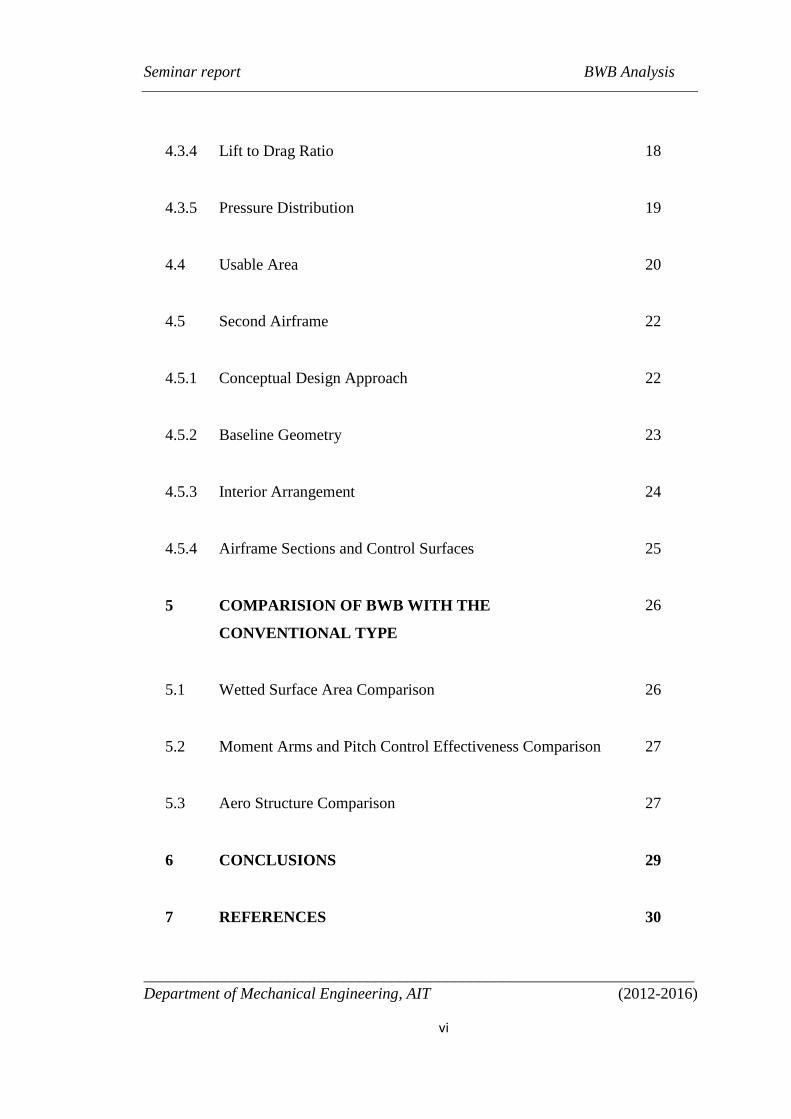
1 INTRODUCTION 1
2 LITERATURE REVIEW 2
2.1 Historical Background 2
2.2 Research projects in BWB by European Union 7
3 AERODYNAMICS 9
3.1 What is Aerodynamics 9
3.2 Aerodynamic Drag 9
3.2.1 Drag Coefficient 9
Seminar report BWB Analysis
_____________________________________________________________________
Department of Mechanical Engineering, AIT (2012-2016)
v
3.3 Aerodynamic Lift 10
3.3.1 Lift Coefficient 10
3.4 Lift to Drag Ratio 11
3.5 Pitching Moment 11
3.5.1 Pitching Moment Coefficient 12
4 AERODYNAMIC DESIGN EVALUATION OF BWB 13
4.1 Design methodology 13
4.2 The First Airframe 13
4.2.1 The Design Approach 13
4.2.2 Baseline Geometry 15
4.3 Aerodynamic Performance 15
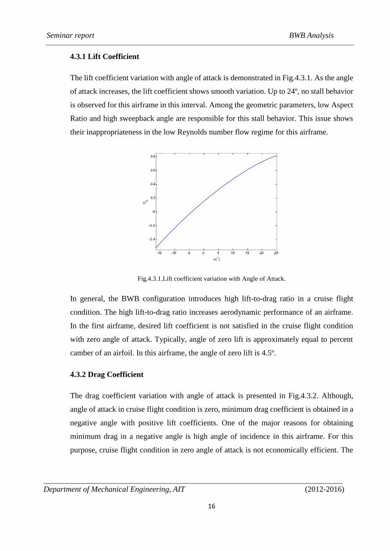
4.3.1 Lift Coefficient 16
4.3.2 Drag Coefficient 16
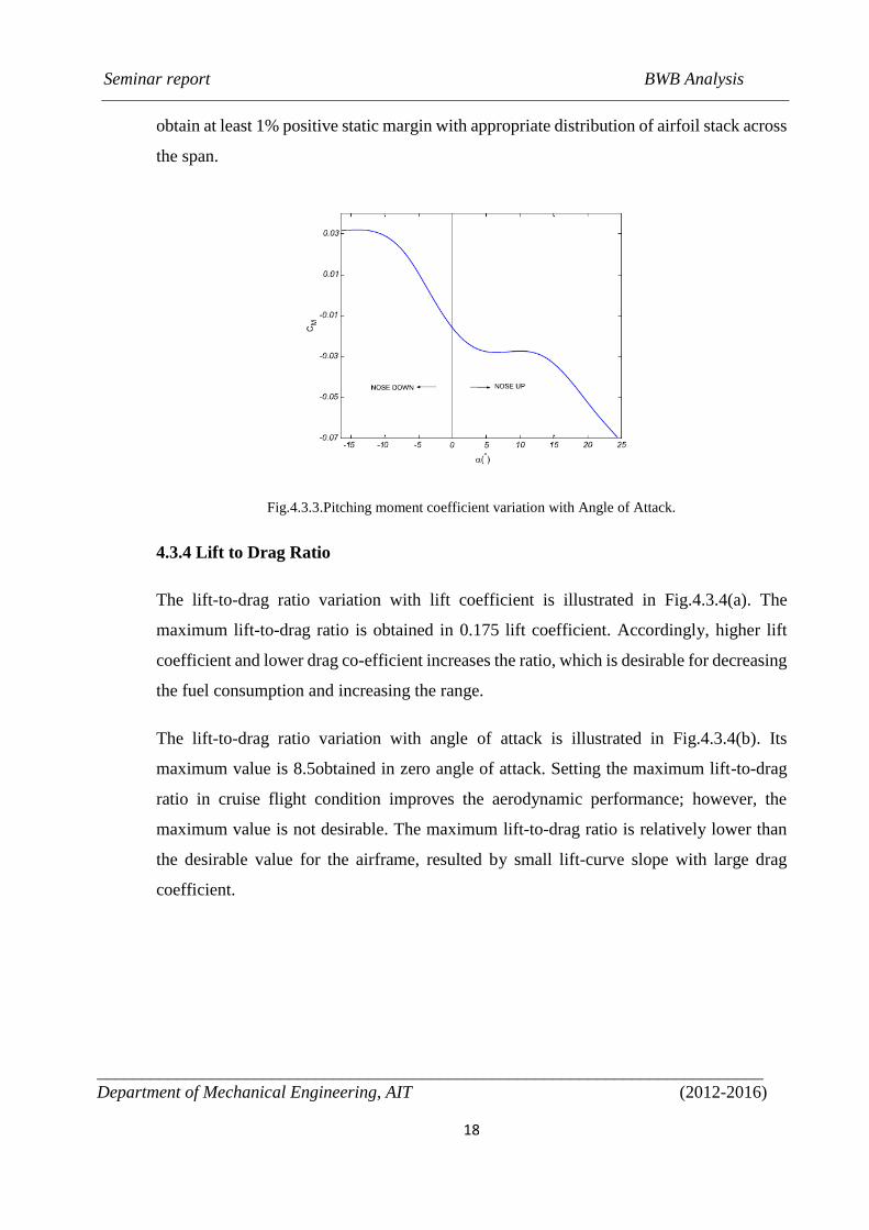
4.3.3 Pitching Moment Coefficient 17
Seminar report BWB Analysis
_____________________________________________________________________
Department of Mechanical Engineering, AIT (2012-2016)
vi
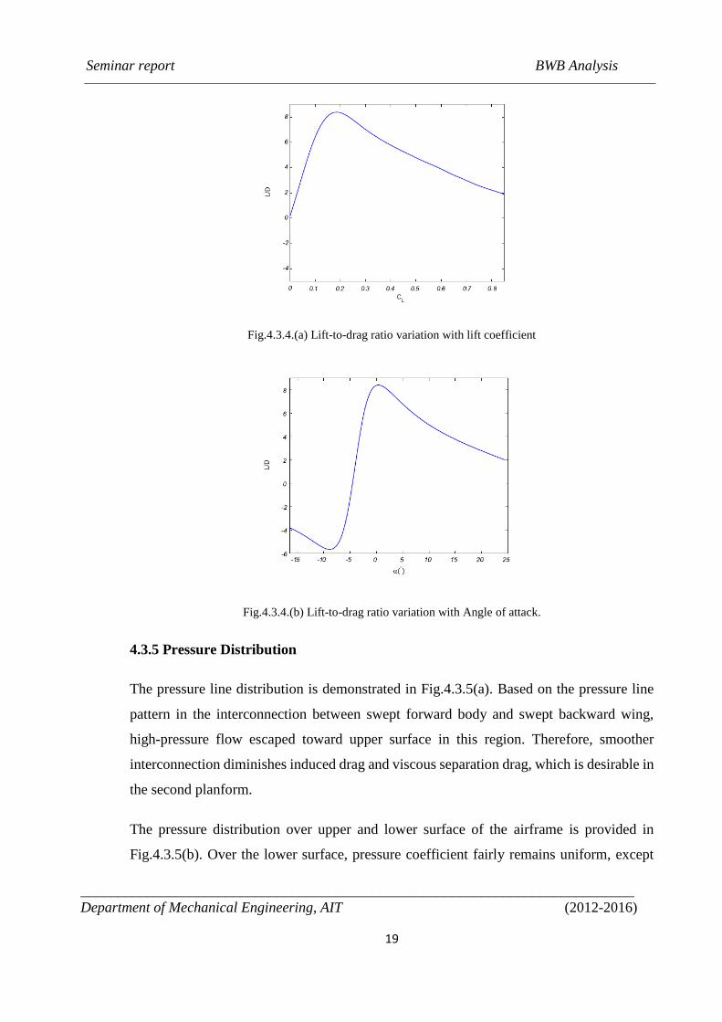
4.3.4 Lift to Drag Ratio 18
4.3.5 Pressure Distribution 19
4.4 Usable Area 20
4.5 Second Airframe 22
4.5.1 Conceptual Design Approach 22
4.5.2 Baseline Geometry 23
4.5.3 Interior Arrangement 24
4.5.4 Airframe Sections and Control Surfaces 25
5 COMPARISION OF BWB WITH THE
CONVENTIONAL TYPE
26
5.1 Wetted Surface Area Comparison 26
5.2 Moment Arms and Pitch Control Effectiveness Comparison 27
5.3 Aero Structure Comparison 27
6 CONCLUSIONS 29
7 REFERENCES 30
Seminar report BWB Analysis
_____________________________________________________________________
Department of Mechanical Engineering, AIT (2012-2016)
vii
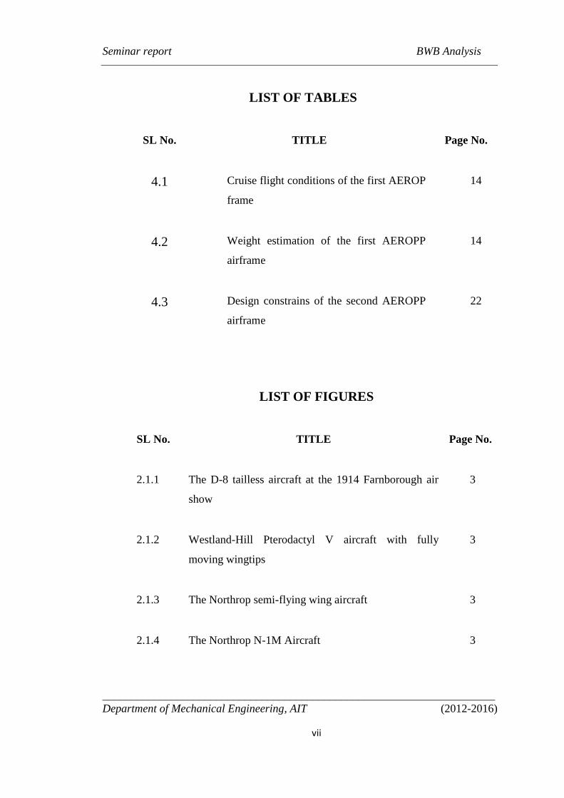
LIST OF TABLES
SL No. TITLE Page No.
4.1 Cruise flight conditions of the first AEROP
frame
14
4.2 Weight estimation of the first AEROPP
airframe
14
4.3 Design constrains of the second AEROPP
airframe
22
LIST OF FIGURES
SL No. TITLE Page No.
2.1.1 The D-8 tailless aircraft at the 1914 Farnborough air
show
3
2.1.2 Westland-Hill Pterodactyl V aircraft with fully
moving wingtips
3
2.1.3 The Northrop semi-flying wing aircraft 3
2.1.4 The Northrop N-1M Aircraft 3
Seminar report BWB Analysis
_____________________________________________________________________
Department of Mechanical Engineering, AIT (2012-2016)
viii
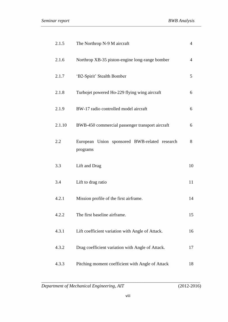
2.1.5 The Northrop N-9 M aircraft 4
2.1.6 Northrop XB-35 piston-engine long-range bomber 4
2.1.7 ‘B2-Spirit’ Stealth Bomber 5
2.1.8 Turbojet powered Ho-229 flying wing aircraft 6
2.1.9 BW-17 radio controlled model aircraft 6
2.1.10 BWB-450 commercial passenger transport aircraft 6
2.2 European Union sponsored BWB-related research
programs
8
3.3 Lift and Drag 10
3.4 Lift to drag ratio 11
4.2.1 Mission profile of the first airframe. 14
4.2.2 The first baseline airframe. 15
4.3.1 Lift coefficient variation with Angle of Attack. 16
4.3.2 Drag coefficient variation with Angle of Attack. 17
4.3.3 Pitching moment coefficient with Angle of Attack 18
Seminar report BWB Analysis
_____________________________________________________________________
Department of Mechanical Engineering, AIT (2012-2016)
ix
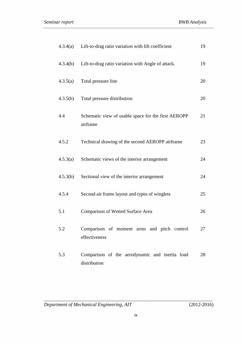
4.3.4(a) Lift-to-drag ratio variation with lift coefficient 19
4.3.4(b) Lift-to-drag ratio variation with Angle of attack. 19
4.3.5(a) Total pressure line 20
4.3.5(b) Total pressure distribution 20
4.4 Schematic view of usable space for the first AEROPP
airframe
21
4.5.2 Technical drawing of the second AEROPP airframe 23
4.5.3(a) Schematic views of the interior arrangement 24
4.5.3(b) Sectional view of the interior arrangement 24
4.5.4 Second air frame layout and types of winglets 25
5.1 Comparison of Wetted Surface Area 26
5.2 Comparison of moment arms and pitch control
effectiveness
27
5.3 Comparison of the aerodynamic and inertia load
distribution
28
Seminar report BWB Analysis
_____________________________________________________________________
Department of Mechanical Engineering, AIT (2012-2016)
x
LIST OF ABBREVATIONS
BWB Blended Wing Body
L/D Lift to Drag Ratio
NASA National Aeronautics and Space Administration
MDC McDonnell Douglas Corporation
BLI Boundary Layer Ingestion
VELA Very Efficient Large Aircraft
MOB Multidisciplinary Optimizations of a Blended Wing Body
NACRE New Aircraft Concept Research
Seminar report BWB Analysis
____________________________________________________________________________
Department of Mechanical Engineering, AIT (2012-2016)
1
CHAPTER 1
INTRODUCTION
An aircraft is a machine that is able to fly by gaining support from the air. It
counters the force of gravity by using either static lift or by using the dynamic lift of
an airfoil or in a few cases the downward thrust from jet engines. Before the renewed
interest in unconventional aircraft configurations, the design of aircraft centred on the
improvement of the efficiency of the conventional tube and wing design. However, having
reached the limit of conventional design coupled with a growing demand for an
environmentally friendly, aerodynamically efficient aircraft that can carry large number of
passengers over long ranges at reduced direct operating cost, the BWB aircraft was
conceptualised. The BWB has low noise signature because it does not require flaps or tail
plane for pitch control hence removing the need for trailing edge and possibly leading edge
devices in take-off and landing. It also emits less pollutants due to reduced fuel burn and
propulsive efficiency. The BWB offers increased range and payload capacity due to 27%
reduction in fuel burn per seat leading to reduced direct operating costs. These advantages
are enabled by blending a lift generating centre-body housing the payload with
conventional outer wings, to obtain a compact aerodynamically efficient flying wing
providing structural, aerodynamic and payload synergy. The BWB however differs from a
pure flying wing in that a pure flying wing has straight leading and trailing edges with no
definite fuselage. Payloads in a flying wing aircraft are stored in the main wing structure.
On the other hand, a BWB consists of a flattened fuselage for accommodating payload.
Other advantages of the BWB design includes 15–20% increased lift to drag ratio (L/D)
due to reduced drag resulting from a 33% lower wetted surface area compared to a
conventional tube and wing aircraft.
Seminar report BWB Analysis
____________________________________________________________________________
Department of Mechanical Engineering, AIT (2012-2016)
2
CHAPTER 2
LITERATURE REVIEW
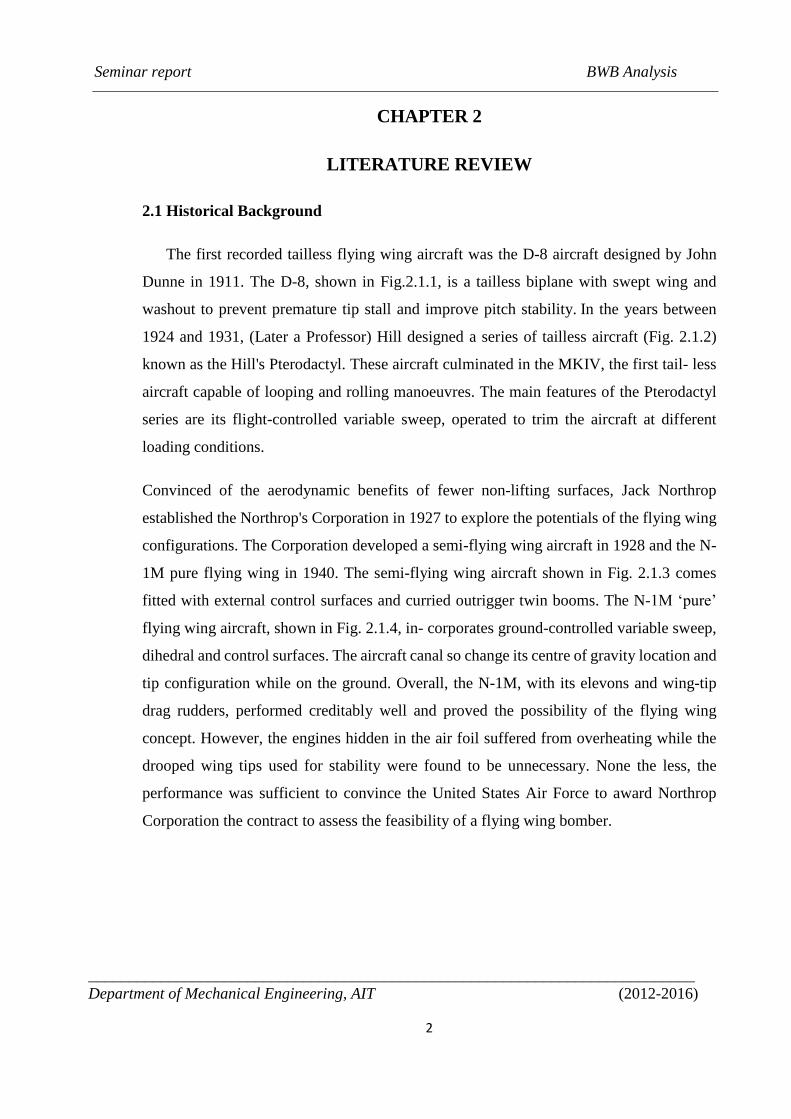
2.1 Historical Background
The first recorded tailless flying wing aircraft was the D-8 aircraft designed by John
Dunne in 1911. The D-8, shown in Fig.2.1.1, is a tailless biplane with swept wing and
washout to prevent premature tip stall and improve pitch stability. In the years between
1924 and 1931, (Later a Professor) Hill designed a series of tailless aircraft (Fig. 2.1.2)
known as the Hill's Pterodactyl. These aircraft culminated in the MKIV, the first tail- less
aircraft capable of looping and rolling manoeuvres. The main features of the Pterodactyl
series are its flight-controlled variable sweep, operated to trim the aircraft at different
loading conditions.
Convinced of the aerodynamic benefits of fewer non-lifting surfaces, Jack Northrop
established the Northrop's Corporation in 1927 to explore the potentials of the flying wing
configurations. The Corporation developed a semi-flying wing aircraft in 1928 and the N-
1M pure flying wing in 1940. The semi-flying wing aircraft shown in Fig. 2.1.3 comes
fitted with external control surfaces and curried outrigger twin booms. The N-1M ‘pure’
flying wing aircraft, shown in Fig. 2.1.4, in- corporates ground-controlled variable sweep,
dihedral and control surfaces. The aircraft canal so change its centre of gravity location and
tip configuration while on the ground. Overall, the N-1M, with its elevons and wing-tip
drag rudders, performed creditably well and proved the possibility of the flying wing
concept. However, the engines hidden in the air foil suffered from overheating while the
drooped wing tips used for stability were found to be unnecessary. None the less, the
performance was sufficient to convince the United States Air Force to award Northrop
Corporation the contract to assess the feasibility of a flying wing bomber.
Seminar report BWB Analysis
____________________________________________________________________________
Department of Mechanical Engineering, AIT (2012-2016)
3
Fig. 2.1.1. The D-8 tailless aircraft at the 1914 Farnborough air show
Fig. 2.1.2. Westland-Hill Pterodactyl V aircraft with fully moving wingtips
Fig. 2.1.3. The Northrop semi-flying wing aircraft (Source: Smithsonian NASA Museum).
Fig. 2.1.4. The Northrop N-1M Aircraft (Source: Smithsonian NASA Museum).
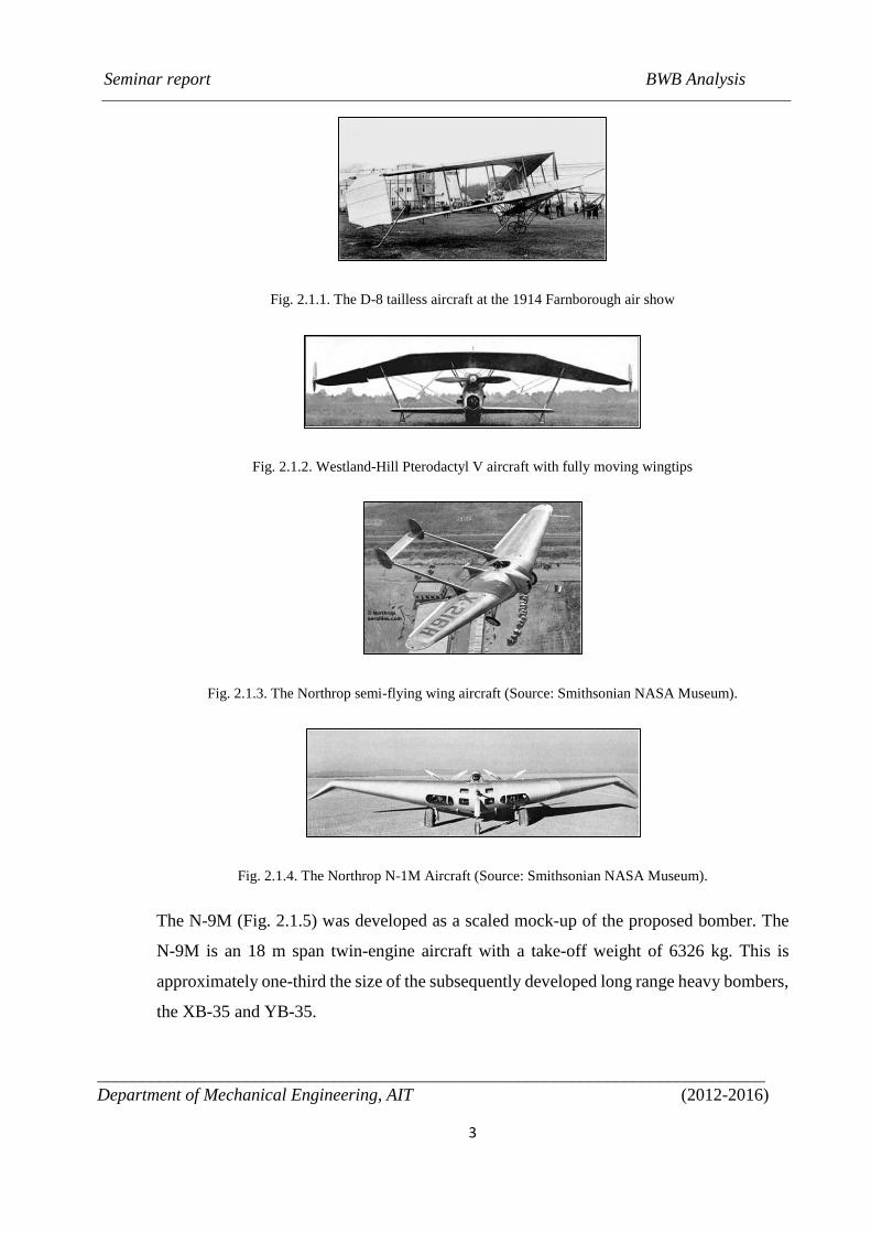
The N-9M (Fig. 2.1.5) was developed as a scaled mock-up of the proposed bomber. The
N-9M is an 18 m span twin-engine aircraft with a take-off weight of 6326 kg. This is
approximately one-third the size of the subsequently developed long range heavy bombers,
the XB-35 and YB-35.
Seminar report BWB Analysis
____________________________________________________________________________
Department of Mechanical Engineering, AIT (2012-2016)
4
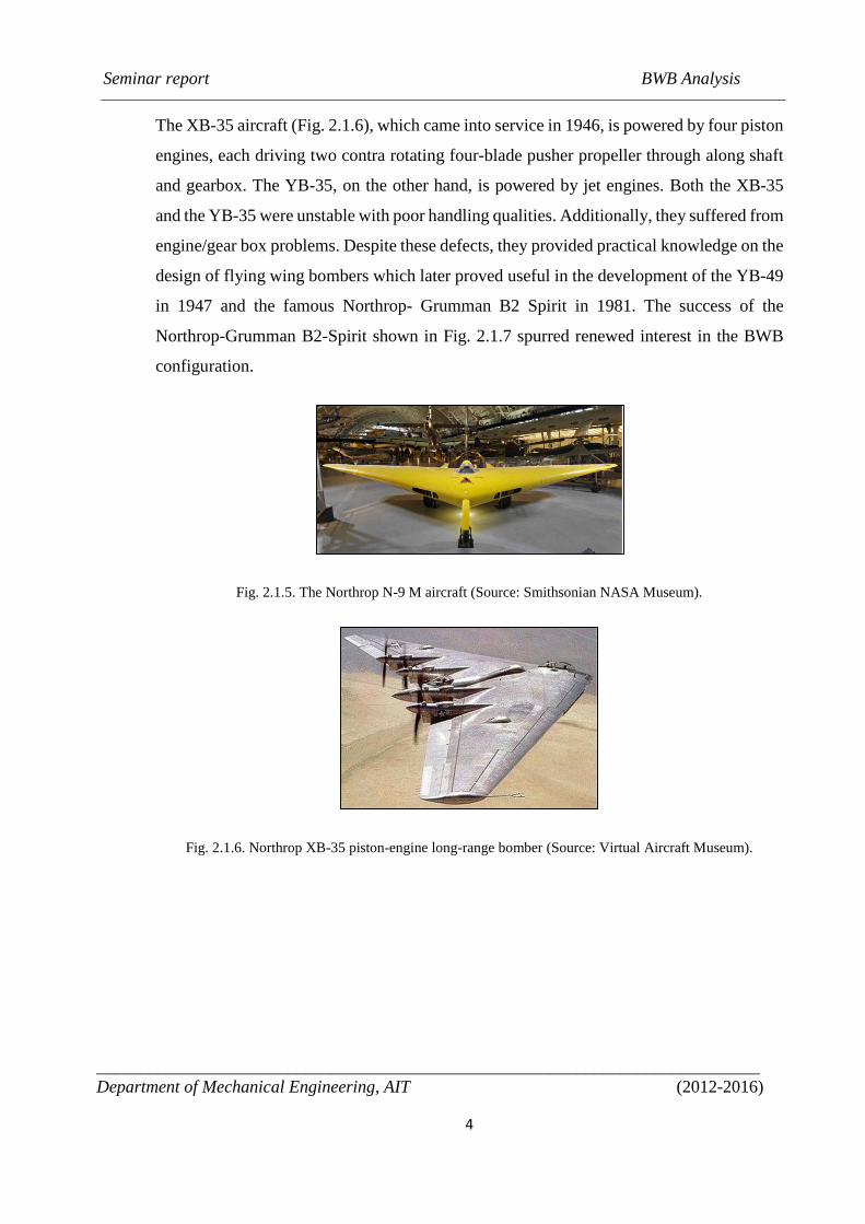
The XB-35 aircraft (Fig. 2.1.6), which came into service in 1946, is powered by four piston
engines, each driving two contra rotating four-blade pusher propeller through along shaft
and gearbox. The YB-35, on the other hand, is powered by jet engines. Both the XB-35
and the YB-35 were unstable with poor handling qualities. Additionally, they suffered from
engine/gear box problems. Despite these defects, they provided practical knowledge on the
design of flying wing bombers which later proved useful in the development of the YB-49
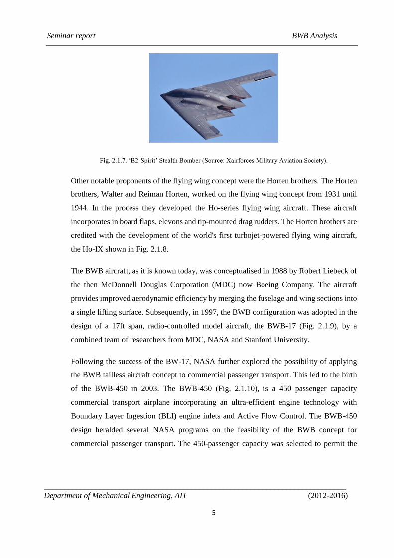
in 1947 and the famous Northrop- Grumman B2 Spirit in 1981. The success of the
Northrop-Grumman B2-Spirit shown in Fig. 2.1.7 spurred renewed interest in the BWB
configuration.
Fig. 2.1.5. The Northrop N-9 M aircraft (Source: Smithsonian NASA Museum).
Fig. 2.1.6. Northrop XB-35 piston-engine long-range bomber (Source: Virtual Aircraft Museum).
Seminar report BWB Analysis
____________________________________________________________________________
Department of Mechanical Engineering, AIT (2012-2016)
5
Fig. 2.1.7. ‘B2-Spirit’ Stealth Bomber (Source: Xairforces Military Aviation Society).
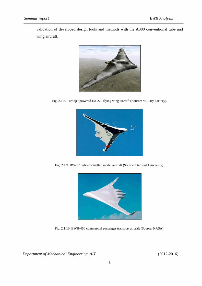
Other notable proponents of the flying wing concept were the Horten brothers. The Horten
brothers, Walter and Reiman Horten, worked on the flying wing concept from 1931 until
1944. In the process they developed the Ho-series flying wing aircraft. These aircraft
incorporates in board flaps, elevons and tip-mounted drag rudders. The Horten brothers are
credited with the development of the world's first turbojet-powered flying wing aircraft,
the Ho-IX shown in Fig. 2.1.8.
The BWB aircraft, as it is known today, was conceptualised in 1988 by Robert Liebeck of
the then McDonnell Douglas Corporation (MDC) now Boeing Company. The aircraft
provides improved aerodynamic efficiency by merging the fuselage and wing sections into
a single lifting surface. Subsequently, in 1997, the BWB configuration was adopted in the
design of a 17ft span, radio-controlled model aircraft, the BWB-17 (Fig. 2.1.9), by a
combined team of researchers from MDC, NASA and Stanford University.
Following the success of the BW-17, NASA further explored the possibility of applying
the BWB tailless aircraft concept to commercial passenger transport. This led to the birth
of the BWB-450 in 2003. The BWB-450 (Fig. 2.1.10), is a 450 passenger capacity
commercial transport airplane incorporating an ultra-efficient engine technology with
Boundary Layer Ingestion (BLI) engine inlets and Active Flow Control. The BWB-450
design heralded several NASA programs on the feasibility of the BWB concept for
commercial passenger transport. The 450-passenger capacity was selected to permit the
Seminar report BWB Analysis
____________________________________________________________________________
Department of Mechanical Engineering, AIT (2012-2016)
6
validation of developed design tools and methods with the A380 conventional tube and
wing aircraft.
Fig. 2.1.8. Turbojet powered Ho-229 flying wing aircraft (Source: Military Factory).
Fig. 2.1.9. BW-17 radio controlled model aircraft (Source: Stanford University).
Fig. 2.1.10. BWB-450 commercial passenger transport aircraft (Source: NASA).
Seminar report BWB Analysis
____________________________________________________________________________
Department of Mechanical Engineering, AIT (2012-2016)
7
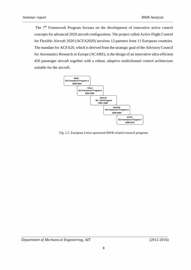
2.2 Research projects in BWB by European Union
The anticipated benefits of the BWB concept spurred several organisations into researches
on various aspects of the aircraft. Notable among the researches is the European Union
(EU) 5-tiered project to develop innovative, efficient long range, large capacity passenger
transport and cargo aircraft. The project comprised 3 wholly EU framework Programs and
a program jointly funded by the EU and the United States. The 3 EU Framework Programs
are the 5th, 6th and 7th EU Framework Programs. The 5th EU Framework Program consists
of the Multidisciplinary Optimisation of a Blended Wing Body (MOB) and the Very
Efficient Large Aircraft (VELA) projects. The MOB project is a 3 year research project
carried out in distributed environments across 4 European countries. The project involved
15 partners. This includes 3 aerospace companies, 4 research institutes and 8 universities.
The aim of the MOB project was to develop tools and methods that will enable distributed
design teams to create innovative and complex aeronautical products using either
commercial off the shelf methods or proprietary codes. The VELA project was setup to
develop the necessary skills set, capabilities and methodologies appropriate to the design
and optimisation of Very Efficient Large Aircraft concepts. The VELA project, which ran
from 2002 to 2005, investigated 2 extremes of a BWB configuration, in terms of the
placement and blending of the outboard wing.
The 6th Framework Programme also known as the New Aircraft Concept Research
(NACRE) began in 2005 and was completed in 2009. The NACRE Integrated Project was
undertaken to integrate and validate technologies that enable new aircraft concepts to be
assessed. The NACRE project, which was led by Airbus, involved 36 partners from 13
European countries. The NACRE project advanced the design of BWB aircraft through its
Passenger- driven Flying Wing (PFW) configuration.
Cambridge and MIT investigated the feasibility of an ultra-low noise, fuel efficient BWB,
dubbed the Silent Aircraft Initiative (SAI). The SAI was an ambitious 3-year project by a
team of 35 researchers, beginning in 2002. The research was aimed to design an airplane
that is radically quieter than current passenger transport aircraft.
Seminar report BWB Analysis
____________________________________________________________________________
Department of Mechanical Engineering, AIT (2012-2016)
8
The 7th Framework Program focuses on the development of innovative active control
concepts for advanced 2020 aircraft configuration. The project called Active Flight Control
for Flexible Aircraft 2020 (ACFA2020) involves 13 partners from 11 European countries.
The mandate for ACFA20, which is derived from the strategic goal of the Advisory Council
for Aeronautics Research in Europe (ACARE), is the design of an innovative ultra-efficient
450 passenger aircraft together with a robust, adaptive multichannel control architecture
suitable for the aircraft.
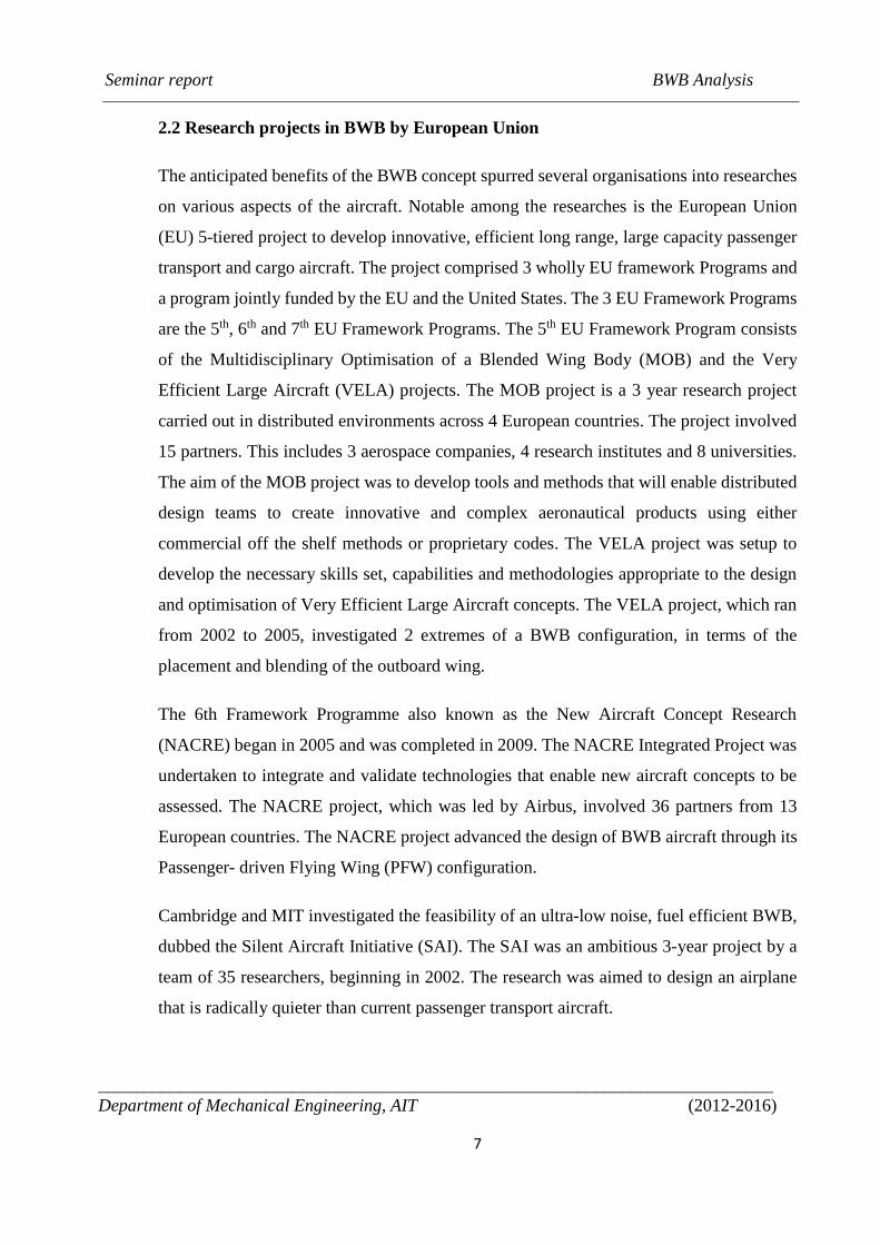
Fig. 2.2. European Union sponsored BWB-related research programs
Seminar report BWB Analysis
____________________________________________________________________________
Department of Mechanical Engineering, AIT (2012-2016)
9
CHAPTER 3
AERODYNAMICS
3.1 What is Aerodynamics?
Aerodynamics is the study of how gases interact with moving bodies. Because the
gas that we encounter most is air, aerodynamics is primarily concerned with the forces of
drag and lift, which are caused by air passing over and around solid bodies. Engineers
apply the principles of aerodynamics to the designs of many different things, including
buildings, bridges and even soccer balls; however, of primary concern is the aerodynamics
of aircraft and automobiles. Aerodynamics comes into play in the study of flight and the
science of building and operating an aircraft, which is called aeronautics. Aeronautical
engineers use the fundamentals of aerodynamics to design aircraft that fly through the
Earth's atmosphere.
3.2 Aerodynamic Drag
The most significant aerodynamic force that applies to nearly everything that moves
through the air is drag. Drag is the force that opposes an aircraft's motion through the air.
Drag is generated in the direction the air is moving when it encounters a solid object. In
most cases, such as in automobiles and aircraft, drag is undesirable because it takes power
to overcome it.
3.2.1 Drag Coefficient
The drag coefficient is a dimensionless quantity that is used to quantify the drag or
resistance of an object in a fluid environment, such as air or water. It is used in the drag
equation, where a lower drag coefficient indicates the object will have less aerodynamic or
hydrodynamic drag. The drag coefficient is always associated with a particular surface
area.
Seminar report BWB Analysis
____________________________________________________________________________
Department of Mechanical Engineering, AIT (2012-2016)
10
The drag coefficient Cd is defined as:
𝐶𝑑 =2𝐹𝑑𝜌𝑢2𝐴
Where:
Fd is the drag force, which is by definition the force component in the direction of
the flow velocity
ρ is the mass density of the fluid
u is the flow speed of the object relative to the fluid,
A is the reference area
3.3 Aerodynamic Lift
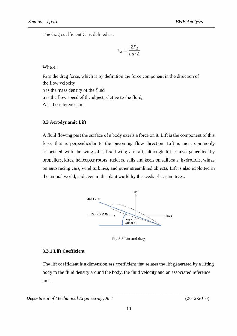
A fluid flowing past the surface of a body exerts a force on it. Lift is the component of this
force that is perpendicular to the oncoming flow direction. Lift is most commonly
associated with the wing of a fixed-wing aircraft, although lift is also generated by
propellers, kites, helicopter rotors, rudders, sails and keels on sailboats, hydrofoils, wings
on auto racing cars, wind turbines, and other streamlined objects. Lift is also exploited in
the animal world, and even in the plant world by the seeds of certain trees.
Fig.3.3.Lift and drag
3.3.1 Lift Coefficient
The lift coefficient is a dimensionless coefficient that relates the lift generated by a lifting
body to the fluid density around the body, the fluid velocity and an associated reference
area.
Seminar report BWB Analysis
____________________________________________________________________________
Department of Mechanical Engineering, AIT (2012-2016)
11
𝐶𝑙 =2𝐿
𝜌𝑣2𝑆
Where
L is the lift force, ρ is fluid density, v is true airspeed and S is the relevant plan area
3.4 Lift to Drag Ratio
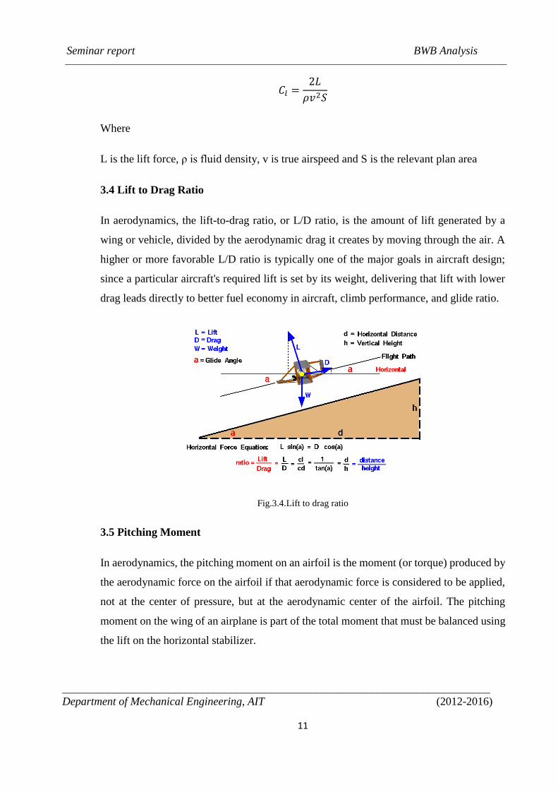
In aerodynamics, the lift-to-drag ratio, or L/D ratio, is the amount of lift generated by a
wing or vehicle, divided by the aerodynamic drag it creates by moving through the air. A
higher or more favorable L/D ratio is typically one of the major goals in aircraft design;
since a particular aircraft's required lift is set by its weight, delivering that lift with lower
drag leads directly to better fuel economy in aircraft, climb performance, and glide ratio.
Fig.3.4.Lift to drag ratio
3.5 Pitching Moment
In aerodynamics, the pitching moment on an airfoil is the moment (or torque) produced by
the aerodynamic force on the airfoil if that aerodynamic force is considered to be applied,
not at the center of pressure, but at the aerodynamic center of the airfoil. The pitching
moment on the wing of an airplane is part of the total moment that must be balanced using
the lift on the horizontal stabilizer.
Seminar report BWB Analysis
____________________________________________________________________________
Department of Mechanical Engineering, AIT (2012-2016)
12
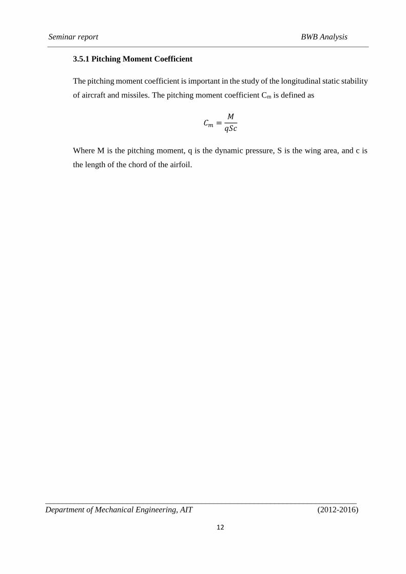
3.5.1 Pitching Moment Coefficient
The pitching moment coefficient is important in the study of the longitudinal static stability
of aircraft and missiles. The pitching moment coefficient Cm is defined as
𝐶𝑚 =𝑀
𝑞𝑆𝑐
Where M is the pitching moment, q is the dynamic pressure, S is the wing area, and c is
the length of the chord of the airfoil.
Seminar report BWB Analysis
____________________________________________________________________________
Department of Mechanical Engineering, AIT (2012-2016)
13
CHAPTER 4
AERODYNAMIC DESIGN EVALUATION OF BWB
4.1 Design Methodology
The first BWB airframe is obtained simply through extruding an S-shaped airfoil
along the span. Provisionally, for opening possible future research opportunity, one-
percent scaled airframe is considered at initial conceptual design layout. Meanwhile,
because aft portion of the central body is appropriate for engine installation and total
pitching moment of the airframe needs to be trimmed in cruise condition, an airfoil with
S-shaped chamber line is chosen.
The second BWB airframe is designed based on computational aerodynamic analyses of
the first airframe. Meanwhile, aircraft conceptual design approach is used for designing the
full-scaled configuration. Accordingly, mission profile includes main and reserved sections
for this airframe. In addition, the interior arrangement and control surfaces are being sized.
The modified airframe is obtained with arranging S-shaped airfoils from central body
toward the span, and then smoothly converting their camber line into form of supercritical
curvature near the outboard wing.
4.2 The First Airframe
The design procedure, including conceptual design approach and baseline geometry, for
the first airframe are introduced. The first airframe is assessed using computational fluid
dynamics. The computational aerodynamic assessment, grid over the baseline geometry,
and implemented computational schemes are also discussed. Meanwhile, longitudinal
stability and pitching moments of the first airframe is investigated afterward. At the end,
usable space is discussed as a major design constraint.
4.2.1 The Design Approach
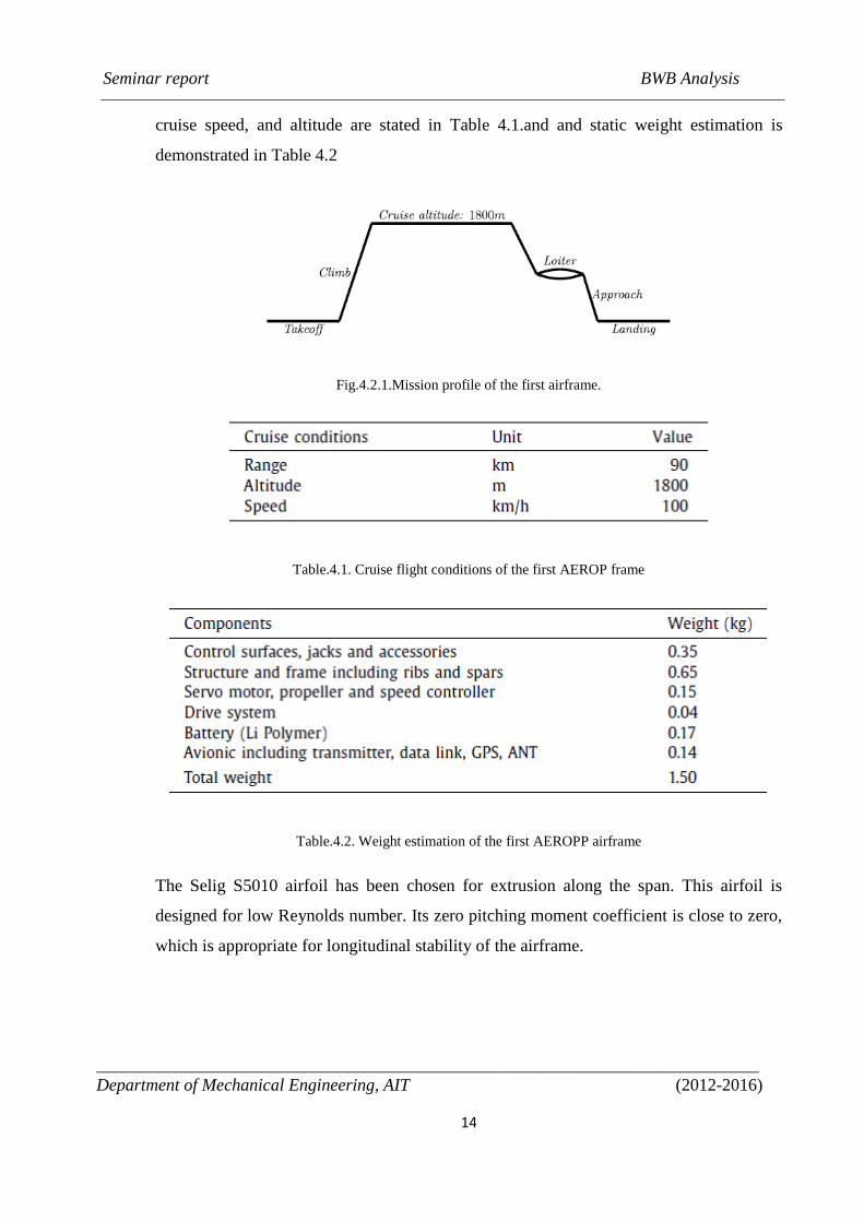
Typical mission profile includes takeoff, climb, cruise, loiter, ap-proach and landing
segments. The mission profile is schematically shown in Fig.4.2.1. Furthermore, range,
Seminar report BWB Analysis
____________________________________________________________________________
Department of Mechanical Engineering, AIT (2012-2016)
14
cruise speed, and altitude are stated in Table 4.1.and and static weight estimation is
demonstrated in Table 4.2
Fig.4.2.1.Mission profile of the first airframe.
Table.4.1. Cruise flight conditions of the first AEROP frame
Table.4.2. Weight estimation of the first AEROPP airframe
The Selig S5010 airfoil has been chosen for extrusion along the span. This airfoil is
designed for low Reynolds number. Its zero pitching moment coefficient is close to zero,
which is appropriate for longitudinal stability of the airframe.
Seminar report BWB Analysis
____________________________________________________________________________
Department of Mechanical Engineering, AIT (2012-2016)
15
4.2.2 Baseline Geometry
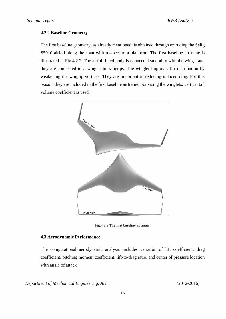
The first baseline geometry, as already mentioned, is obtained through extruding the Selig
S5010 airfoil along the span with re-spect to a planform. The first baseline airframe is
illustrated in Fig.4.2.2. The airfoil-liked body is connected smoothly with the wings, and
they are connected to a winglet in wingtips. The winglet improves lift distribution by
weakening the wingtip vortices. They are important in reducing induced drag. For this
reason, they are included in the first baseline airframe. For sizing the winglets, vertical tail
volume coefficient is used.
Fig.4.2.2.The first baseline airframe.
4.3 Aerodynamic Performance
The computational aerodynamic analysis includes variation of lift coefficient, drag
coefficient, pitching moment coefficient, lift-to-drag ratio, and center of pressure location
with angle of attack.
Seminar report BWB Analysis
____________________________________________________________________________
Department of Mechanical Engineering, AIT (2012-2016)
16
4.3.1 Lift Coefficient
The lift coefficient variation with angle of attack is demonstrated in Fig.4.3.1. As the angle
of attack increases, the lift coefficient shows smooth variation. Up to 24º, no stall behavior
is observed for this airframe in this interval. Among the geometric parameters, low Aspect
Ratio and high sweepback angle are responsible for this stall behavior. This issue shows
their inappropriateness in the low Reynolds number flow regime for this airframe.
Fig.4.3.1.Lift coefficient variation with Angle of Attack.
In general, the BWB configuration introduces high lift-to-drag ratio in a cruise flight
condition. The high lift-to-drag ratio increases aerodynamic performance of an airframe.
In the first airframe, desired lift coefficient is not satisfied in the cruise flight condition
with zero angle of attack. Typically, angle of zero lift is approximately equal to percent
camber of an airfoil. In this airframe, the angle of zero lift is 4.5º.
4.3.2 Drag Coefficient
The drag coefficient variation with angle of attack is presented in Fig.4.3.2. Although,
angle of attack in cruise flight condition is zero, minimum drag coefficient is obtained in a
negative angle with positive lift coefficients. One of the major reasons for obtaining
minimum drag in a negative angle is high angle of incidence in this airframe. For this
purpose, cruise flight condition in zero angle of attack is not economically efficient. The
Seminar report BWB Analysis
____________________________________________________________________________
Department of Mechanical Engineering, AIT (2012-2016)
17
thrust is not minimized in this condition and fuel consumption will raise. Additionally,
maxi-mum lift-to-drag ratio is not gained, which affects the aerodynamic performance of
the airframe. In the second airframe, it is expected choosing appropriate incidence angle
obtains the minimum drag coefficient in between 0ºand 2º angle of attacks.
Fig.4.3.2.Drag coefficient variation with Angle of Attack.
4.3.3 Pitching Moment Coefficient
The pitching moment coefficient variation with angle of attack is demonstrated in
Fig.4.3.3. As angle of attack increases, the pitch-ing moment decreases. According to the
right-hand rule, positive direction of pitching moment around lateral axis is associated with
the counterclockwise rotational direction, indicating downward rotation of nose. The
pitching moment coefficient is negative after −4º, and also the curve slope is negative
before 5º and after of 11º. Therefore, as angle of attack increases, pitching moment
coefficient decreases, implying the airframe’s nose is turning upward. In between 5ºand
11º, pitching moment coefficient is almost con-stant because its curve slope is almost zero.
For this reason, the airframe needs to be considered for pitch up avoidance in climb
condition. In addition, the static margin is negative ratio of pitching moment curve slope
to lift curve slope. From the aforemen-tioned points, the second airframe is expected to
Seminar report BWB Analysis
____________________________________________________________________________
Department of Mechanical Engineering, AIT (2012-2016)
18
obtain at least 1% positive static margin with appropriate distribution of airfoil stack across
the span.
Fig.4.3.3.Pitching moment coefficient variation with Angle of Attack.
4.3.4 Lift to Drag Ratio
The lift-to-drag ratio variation with lift coefficient is illustrated in Fig.4.3.4(a). The
maximum lift-to-drag ratio is obtained in 0.175 lift coefficient. Accordingly, higher lift
coefficient and lower drag co-efficient increases the ratio, which is desirable for decreasing
the fuel consumption and increasing the range.
The lift-to-drag ratio variation with angle of attack is illustrated in Fig.4.3.4(b). Its
maximum value is 8.5obtained in zero angle of attack. Setting the maximum lift-to-drag
ratio in cruise flight condition improves the aerodynamic performance; however, the
maximum value is not desirable. The maximum lift-to-drag ratio is relatively lower than
the desirable value for the airframe, resulted by small lift-curve slope with large drag
coefficient.
Seminar report BWB Analysis
____________________________________________________________________________
Department of Mechanical Engineering, AIT (2012-2016)
19
Fig.4.3.4.(a) Lift-to-drag ratio variation with lift coefficient
Fig.4.3.4.(b) Lift-to-drag ratio variation with Angle of attack.
4.3.5 Pressure Distribution
The pressure line distribution is demonstrated in Fig.4.3.5(a). Based on the pressure line
pattern in the interconnection between swept forward body and swept backward wing,
high-pressure flow escaped toward upper surface in this region. Therefore, smoother
interconnection diminishes induced drag and viscous separation drag, which is desirable in
the second planform.
The pressure distribution over upper and lower surface of the airframe is provided in
Fig.4.3.5(b). Over the lower surface, pressure coefficient fairly remains uniform, except
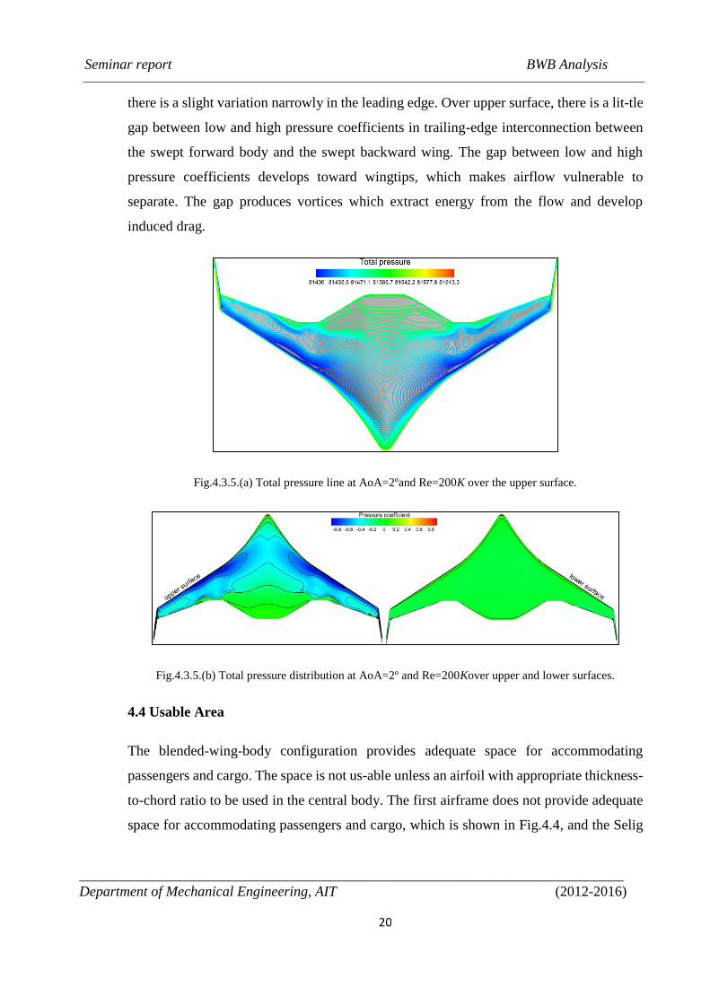
Seminar report BWB Analysis
____________________________________________________________________________
Department of Mechanical Engineering, AIT (2012-2016)
20
there is a slight variation narrowly in the leading edge. Over upper surface, there is a lit-tle
gap between low and high pressure coefficients in trailing-edge interconnection between
the swept forward body and the swept backward wing. The gap between low and high
pressure coefficients develops toward wingtips, which makes airflow vulnerable to
separate. The gap produces vortices which extract energy from the flow and develop
induced drag.
Fig.4.3.5.(a) Total pressure line at AoA=2ºand Re=200K over the upper surface.
Fig.4.3.5.(b) Total pressure distribution at AoA=2º and Re=200Kover upper and lower surfaces.
4.4 Usable Area
The blended-wing-body configuration provides adequate space for accommodating
passengers and cargo. The space is not us-able unless an airfoil with appropriate thickness-
to-chord ratio to be used in the central body. The first airframe does not provide adequate
space for accommodating passengers and cargo, which is shown in Fig.4.4, and the Selig
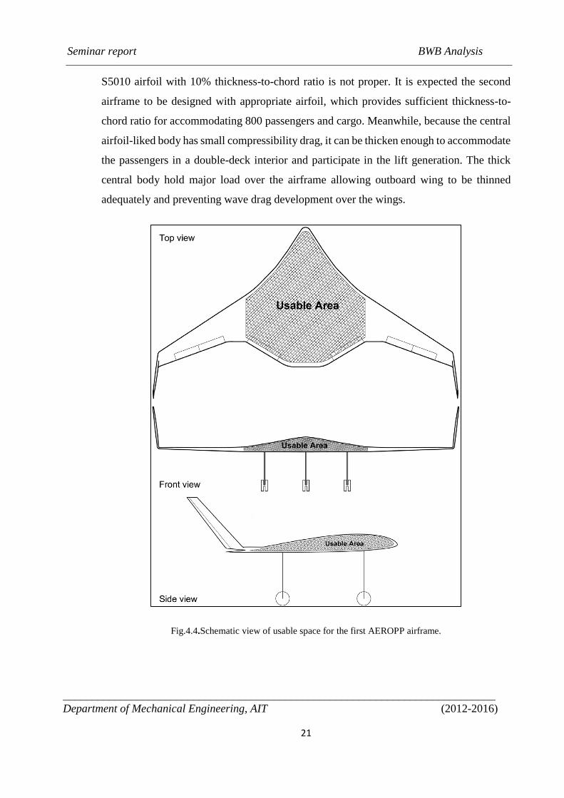
Seminar report BWB Analysis
____________________________________________________________________________
Department of Mechanical Engineering, AIT (2012-2016)
21
S5010 airfoil with 10% thickness-to-chord ratio is not proper. It is expected the second
airframe to be designed with appropriate airfoil, which provides sufficient thickness-to-
chord ratio for accommodating 800 passengers and cargo. Meanwhile, because the central
airfoil-liked body has small compressibility drag, it can be thicken enough to accommodate
the passengers in a double-deck interior and participate in the lift generation. The thick
central body hold major load over the airframe allowing outboard wing to be thinned
adequately and preventing wave drag development over the wings.
Fig.4.4.Schematic view of usable space for the first AEROPP airframe.
Seminar report BWB Analysis
____________________________________________________________________________
Department of Mechanical Engineering, AIT (2012-2016)
22
4.5 The Second Airframe
The second airframe is designed and modified based on evaluation of the first airframe. In
this section, design procedure of the second airframe is described which includes the
conceptual design approach, baseline geometry, interior arrangement, and control surfaces.
4.5.1 Conceptual Design Approach
In the second airframe, required space for 800 passengers is ac-quired by choosing a very
thick airfoil in the central body. Further, thickness-to-chord ratio of the airfoil stack is
changed from 18% to 10% across the span. Other modifications are applied to this air-
frame based on the assessment of the first airframe. Among them, Aspect Ratio of the
wings are increased to improve the maximum lift-to-drag ratio, in particular wetted Aspect
Ratio. Moreover, five different airfoils with different thickness-to-chord ratio are situ-ated
across the span. With respect to the increase of Aspect Ratio, the span is decreased in
comparison with the first airframe. How-ever, the wing area is increased just 33%
comparatively. Design constraints for this airframe is demonstrated in table 4.3.
Table.4.3.Design constrains of the second AEROPP airframe
Seminar report BWB Analysis
____________________________________________________________________________
Department of Mechanical Engineering, AIT (2012-2016)
23
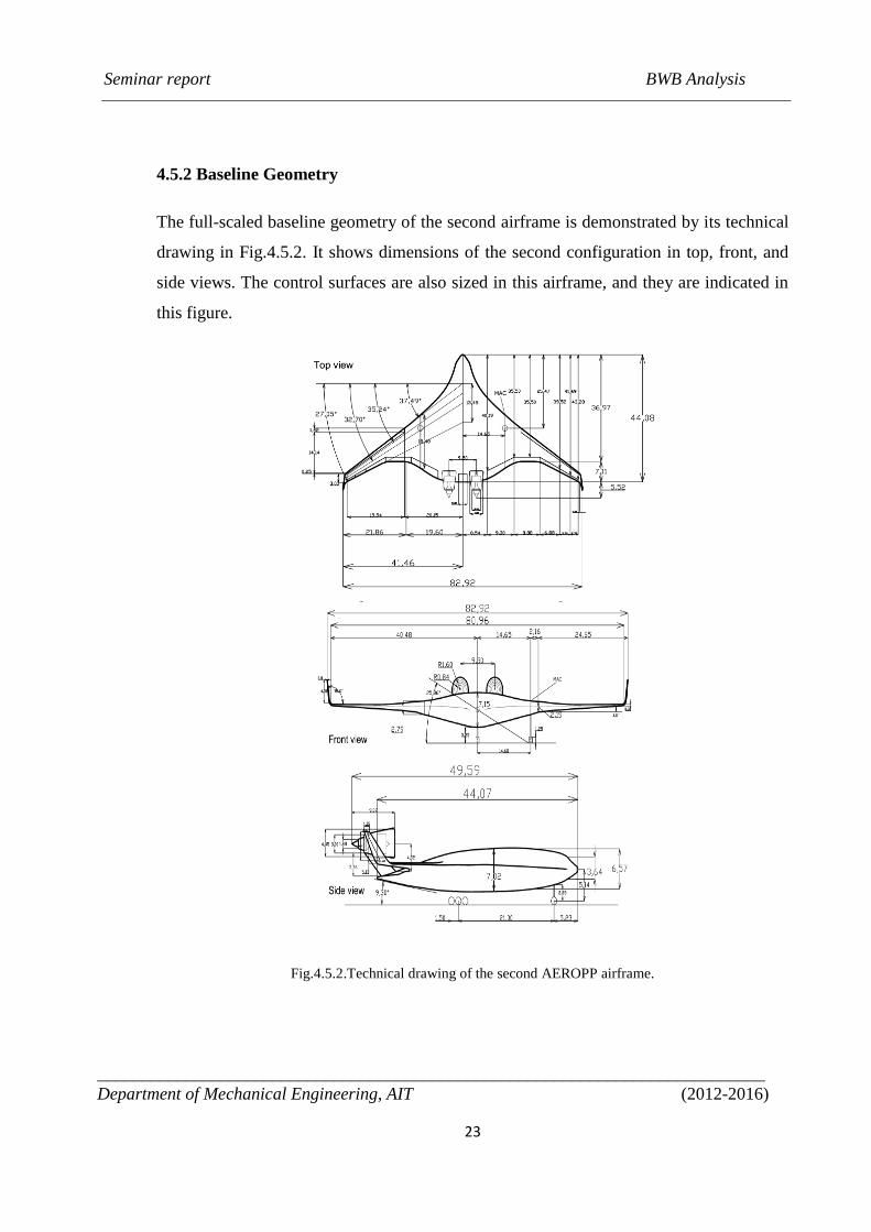
4.5.2 Baseline Geometry
The full-scaled baseline geometry of the second airframe is demonstrated by its technical
drawing in Fig.4.5.2. It shows dimensions of the second configuration in top, front, and
side views. The control surfaces are also sized in this airframe, and they are indicated in
this figure.
Fig.4.5.2.Technical drawing of the second AEROPP airframe.
Seminar report BWB Analysis
____________________________________________________________________________
Department of Mechanical Engineering, AIT (2012-2016)
24
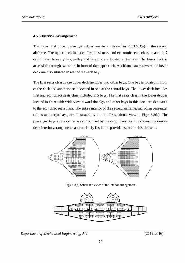
4.5.3 Interior Arrangement
The lower and upper passenger cabins are demonstrated in Fig.4.5.3(a) in the second
airframe. The upper deck includes first, busi-ness, and economic seats class located in 7
cabin bays. In every bay, galley and lavatory are located at the rear. The lower deck is
accessible through two stairs in front of the upper deck. Additional stairs toward the lower
deck are also situated in rear of the each bay.
The first seats class in the upper deck includes two cabin bays. One bay is located in front
of the deck and another one is located in one of the central bays. The lower deck includes
first and economics seats class included in 5 bays. The first seats class in the lower deck is
located in front with wide view toward the sky, and other bays in this deck are dedicated
to the economic seats class. The entire interior of the second airframe, including passenger
cabins and cargo bays, are illustrated by the middle sectional view in Fig.4.5.3(b). The
passenger bays in the center are surrounded by the cargo bays. As it is shown, the double
deck interior arrangements appropriately fits in the provided space in this airframe.
Fig4.5.3(a) Schematic views of the interior arrangement
Seminar report BWB Analysis
____________________________________________________________________________
Department of Mechanical Engineering, AIT (2012-2016)
25
Fig.4.5.3.(b) Sectional view of the interior arrangement.
4.5.4 Airframe sections and control surfaces
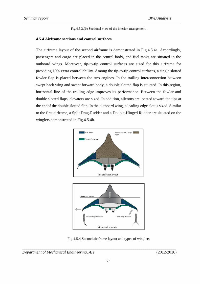
The airframe layout of the second airframe is demonstrated in Fig.4.5.4a. Accordingly,
passengers and cargo are placed in the central body, and fuel tanks are situated in the
outboard wings. Moreover, tip-to-tip control surfaces are sized for this airframe for
providing 10% extra controllability. Among the tip-to-tip control surfaces, a single slotted
fowler flap is placed between the two engines. In the trailing interconnection between
swept back wing and swept forward body, a double slotted flap is situated. In this region,
horizontal line of the trailing edge improves its performance. Between the fowler and
double slotted flaps, elevators are sized. In addition, ailerons are located toward the tips at
the endof the double slotted flap. In the outboard wing, a leading edge slot is sized. Similar
to the first airframe, a Split Drag-Rudder and a Double-Hinged Rudder are situated on the
winglets demonstrated in Fig.4.5.4b.
Fig.4.5.4.Second air frame layout and types of winglets
Seminar report BWB Analysis
____________________________________________________________________________
Department of Mechanical Engineering, AIT (2012-2016)
26
CHAPTER 5
COMPARISON OF BWB DESIGN WITH THE CONVENTIONAL
TYPE
5.1 Wetted Surface Area Comparison
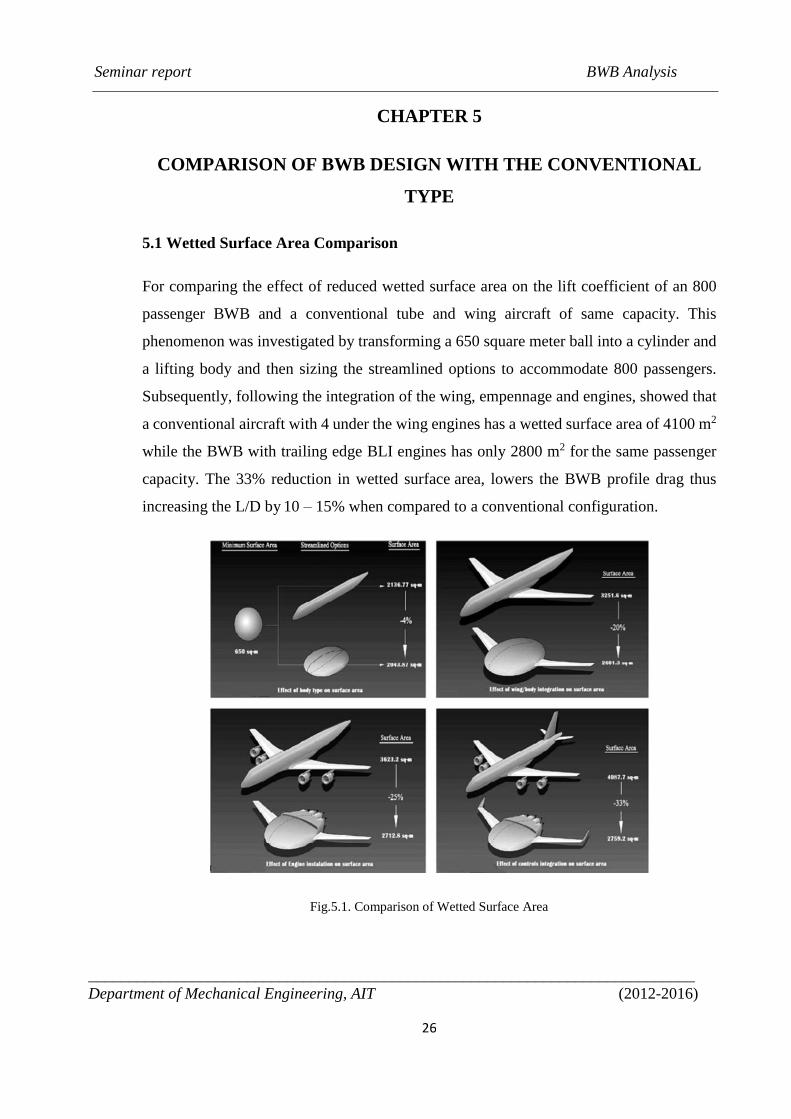
For comparing the effect of reduced wetted surface area on the lift coefficient of an 800
passenger BWB and a conventional tube and wing aircraft of same capacity. This
phenomenon was investigated by transforming a 650 square meter ball into a cylinder and
a lifting body and then sizing the streamlined options to accommodate 800 passengers.
Subsequently, following the integration of the wing, empennage and engines, showed that
a conventional aircraft with 4 under the wing engines has a wetted surface area of 4100 m2
while the BWB with trailing edge BLI engines has only 2800 m2 for the same passenger
capacity. The 33% reduction in wetted surface area, lowers the BWB profile drag thus
increasing the L/D by 10 – 15% when compared to a conventional configuration.
Fig.5.1. Comparison of Wetted Surface Area
Seminar report BWB Analysis
____________________________________________________________________________
Department of Mechanical Engineering, AIT (2012-2016)
27
5.2 Moment Arms and Pitch Control Effectiveness Comparison
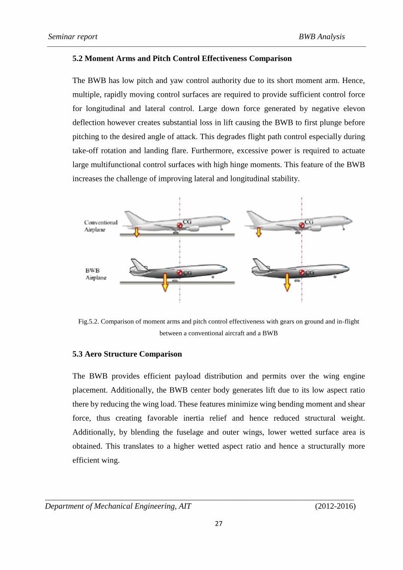
The BWB has low pitch and yaw control authority due to its short moment arm. Hence,
multiple, rapidly moving control surfaces are required to provide sufficient control force
for longitudinal and lateral control. Large down force generated by negative elevon
deflection however creates substantial loss in lift causing the BWB to first plunge before
pitching to the desired angle of attack. This degrades flight path control especially during
take-off rotation and landing flare. Furthermore, excessive power is required to actuate
large multifunctional control surfaces with high hinge moments. This feature of the BWB
increases the challenge of improving lateral and longitudinal stability.
Fig.5.2. Comparison of moment arms and pitch control effectiveness with gears on ground and in-flight
between a conventional aircraft and a BWB
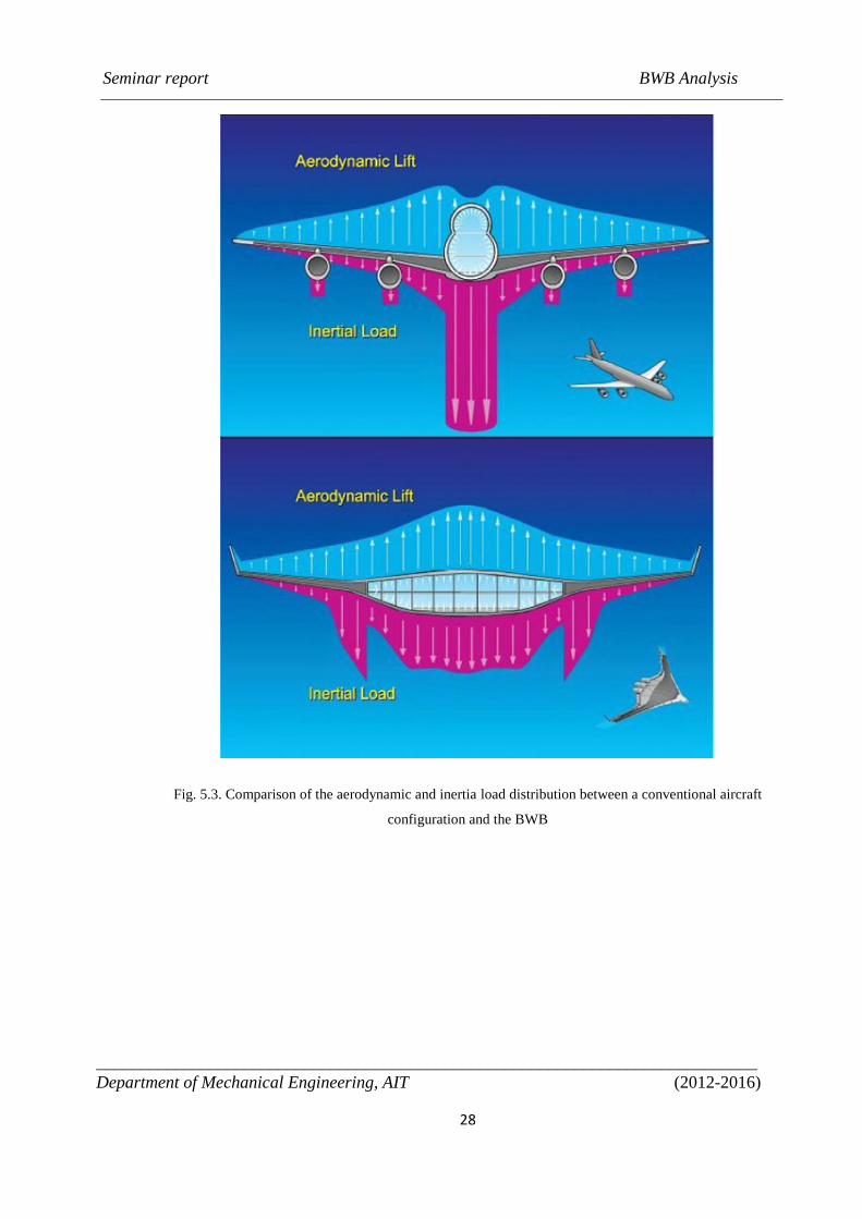
5.3 Aero Structure Comparison
The BWB provides efficient payload distribution and permits over the wing engine
placement. Additionally, the BWB center body generates lift due to its low aspect ratio
there by reducing the wing load. These features minimize wing bending moment and shear
force, thus creating favorable inertia relief and hence reduced structural weight.
Additionally, by blending the fuselage and outer wings, lower wetted surface area is
obtained. This translates to a higher wetted aspect ratio and hence a structurally more
efficient wing.
Seminar report BWB Analysis
____________________________________________________________________________
Department of Mechanical Engineering, AIT (2012-2016)
28
Fig. 5.3. Comparison of the aerodynamic and inertia load distribution between a conventional aircraft
configuration and the BWB
Seminar report BWB Analysis
____________________________________________________________________________
Department of Mechanical Engineering, AIT (2012-2016)
29
CHAPTER 6
CONCLUSIONS
Combining wing and body in the blended-wing-body configuration is an innovative idea
which benefits from its inherent aerodynamic potential. However, it needs creative and
careful re-vision at its stage of evolution as a proper candidate for the future generation of
commercial transport. Aerodynamic performance of a blended-wing-body airframe is
studied with aim of improvement in early stage of the conceptual design. The key design
parameters are identified for two sequential airframes using computational fluid dynamics.
The first airframe is designed as a simple research model and its aerodynamic performance
for a mission profile is investigated. The aerodynamic performance investigation includes
variation of lift, drag, and pitching moment coefficients. Also lift-to-drag ratio, pressure
distribution and usable space are also studied in this airframe. Through this investigation,
advantages and disadvantages of the geometric parameters are identified in the first
airframe. Then, based on assessing the first airframe, the second airframe is designed and
modified. In this airframe, interior arrangement and control sur-faces are also investigated.
In summary, baseline geometries and planform of the first and the second airframes are
compared, and the second airframe is proposed as a high-capacity long-range blended-
wing-body commercial transport. As the future works, aerodynamic shape optimization of
the span wise airfoils and multi objective planform optimization improve performance of
the air-frame further, which are currently under investigation.
Seminar report BWB Analysis
____________________________________________________________________________
Department of Mechanical Engineering, AIT (2012-2016)
30
REFERENCES
[1] Payam Dehpanah, Amir Nejat, ‘THE AERODYNAMIC DESIGN EVALUATION
OF A BLENDED-WING-BODY CONFIGURATION’, Aerospace Science and
Technology 43 (2015) 96–110
[2] P. Okonkwo, H. Smith, ‘REVIEW OF EVOLVING TRENDS IN BLENDED WING
BODY AIRCRAFT DESIGN’, Progress in Aerospace Sciences (2016),
http://dx.doi.org/10.1016/j.paerosci.2015.12.002