Seismic Source Mechanism - 地球進化科学 | 筑波大学yagi-y/text/Source_meca_v0.7.pdfof data...
64
Seismic Source Mechanism Yuji Yagi (University of Tsukuba)
Transcript of Seismic Source Mechanism - 地球進化科学 | 筑波大学yagi-y/text/Source_meca_v0.7.pdfof data...
Seismic Source Mechanism
Yuji Yagi
(University of Tsukuba)
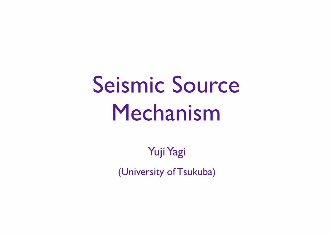
Earthquake
Surface rupture (Taken by Prof. Abe, the University of Tokyo)
Earthquake is a term used to describe both failure process along a fault zone, and the resulting ground
shaking and radiated seismic energy caused by the slip, or by volcanic or magmatic activity, or other sudden
stress changes in the earth.
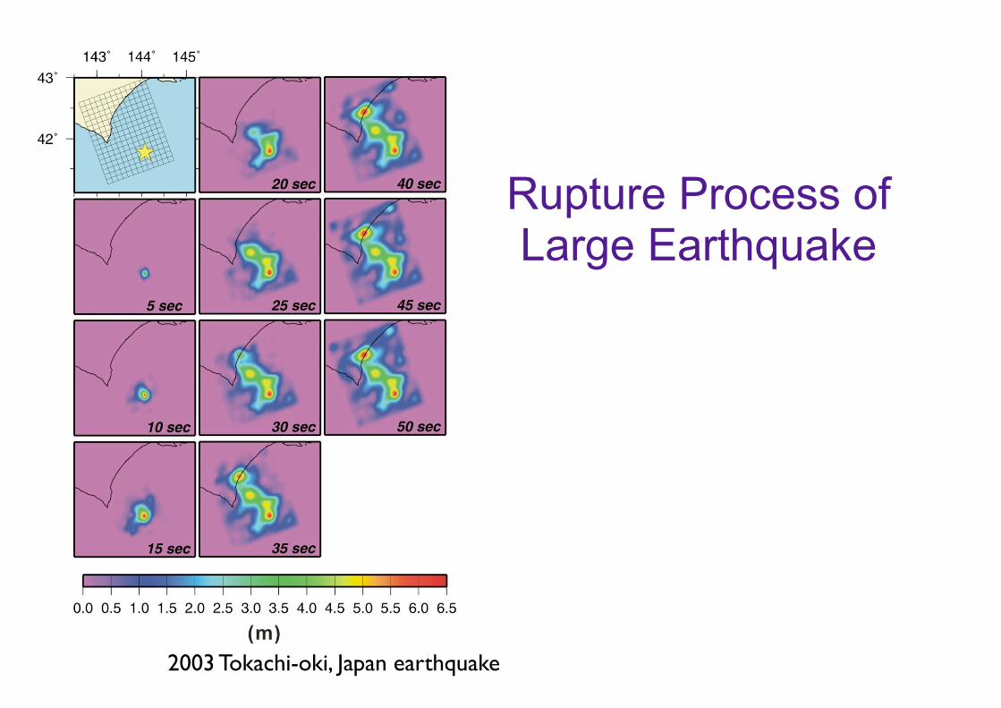
Rupture Process of Large Earthquake
2003 Tokachi-oki, Japan earthquake
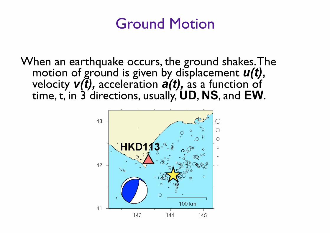
Ground Motion
When an earthquake occurs, the ground shakes. The motion of ground is given by displacement u(t), velocity v(t), acceleration a(t), as a function of time, t, in 3 directions, usually, UD, NS, and EW.
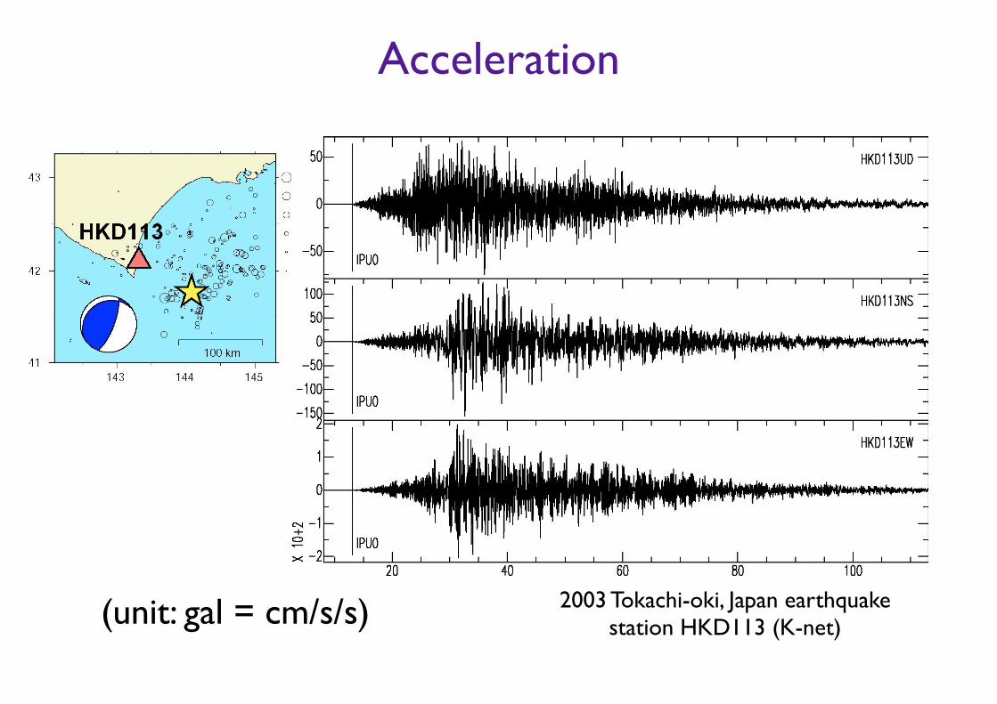
Acceleration
(unit: gal = cm/s/s) 2003 Tokachi-oki, Japan earthquake station HKD113 (K-net)
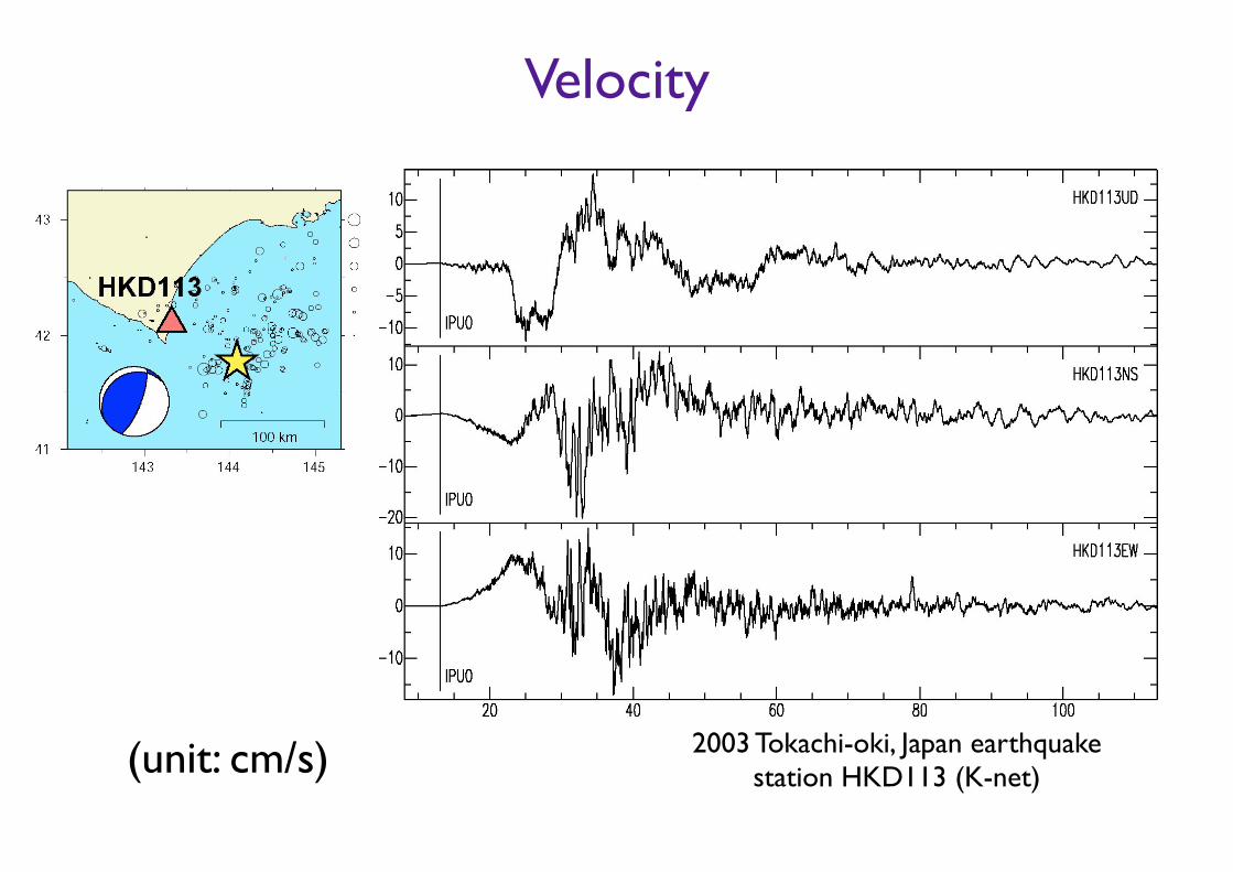
Velocity
(unit: cm/s) 2003 Tokachi-oki, Japan earthquake station HKD113 (K-net)

Displacement
(unit: cm) 2003 Tokachi-oki, Japan earthquake station HKD113 (K-net)
Static Displacement
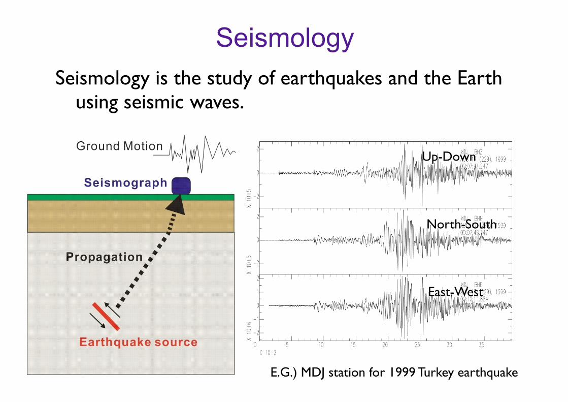
SeismologySeismology is the study of earthquakes and the Earth
using seismic waves.
Up-Down
North-South
East-West
E.G.) MDJ station for 1999 Turkey earthquake
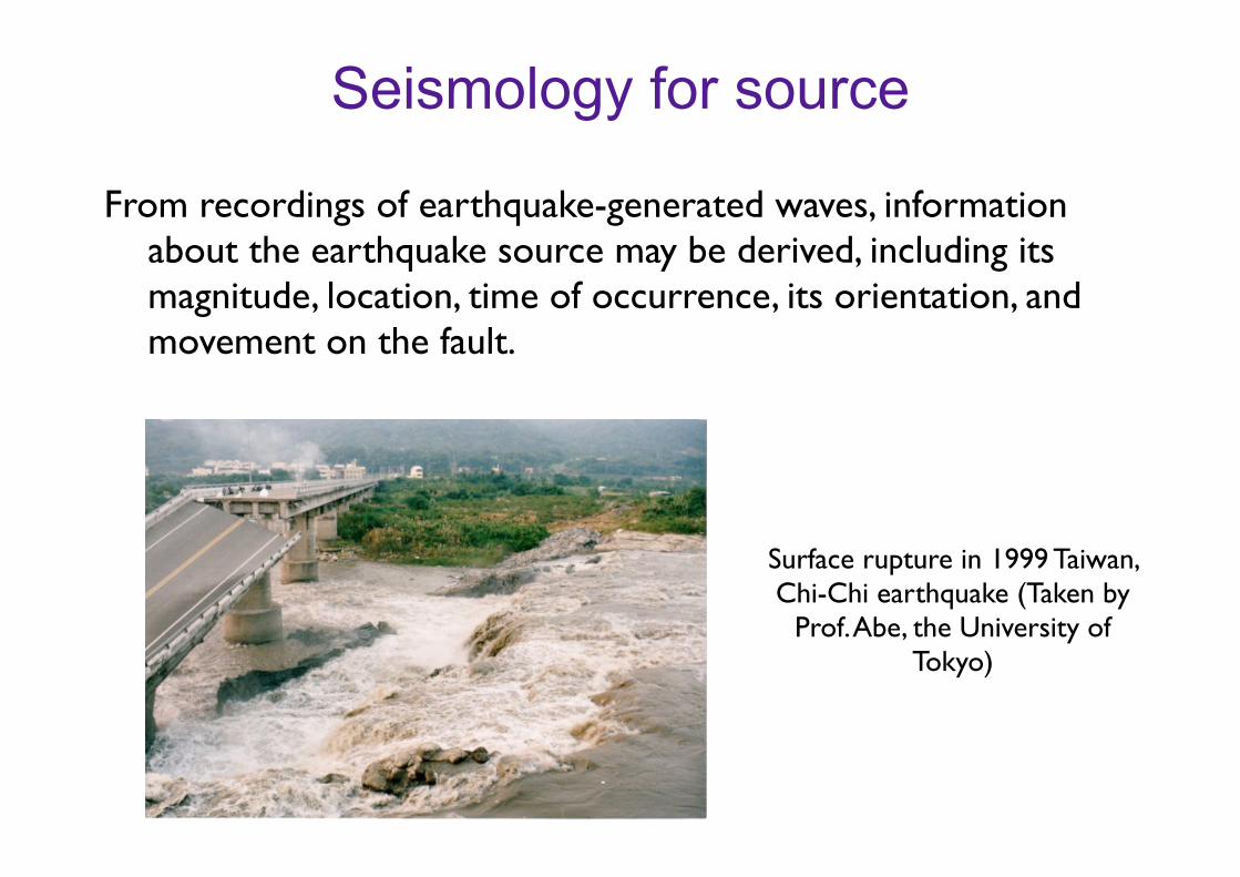
Seismology for source
From recordings of earthquake-generated waves, information about the earthquake source may be derived, including its magnitude, location, time of occurrence, its orientation, and movement on the fault.
Surface rupture in 1999 Taiwan, Chi-Chi earthquake (Taken by
Prof. Abe, the University of Tokyo)
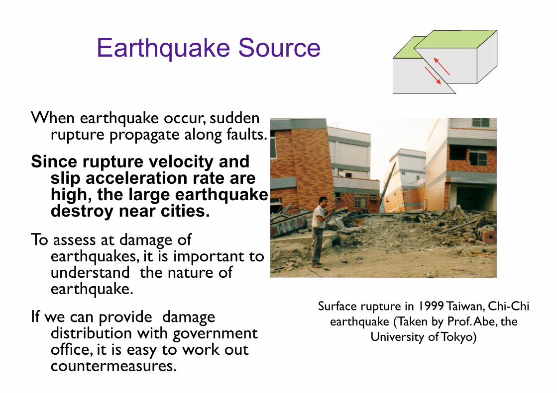
Earthquake Source
When earthquake occur, sudden rupture propagate along faults.
Since rupture velocity and slip acceleration rate are high, the large earthquake destroy near cities.
To assess at damage of earthquakes, it is important to understand the nature of earthquake.
If we can provide damage distribution with government office, it is easy to work out countermeasures.
Surface rupture in 1999 Taiwan, Chi-Chi earthquake (Taken by Prof. Abe, the
University of Tokyo)

Source Parameters
!• Hypocenter (Latitude, Longitude, Depth)
• Origin Time (Start time of earthquake)
• Magnitude (Size of earthquake)
• Faulting Type (focal mechanism)
• Faulting Size (Length, Wide and Dislocation)
• Seismic moment (Size of earthquake)
• Stress Drop (Shear Stress Change)
• Source Process (Rupture Process)
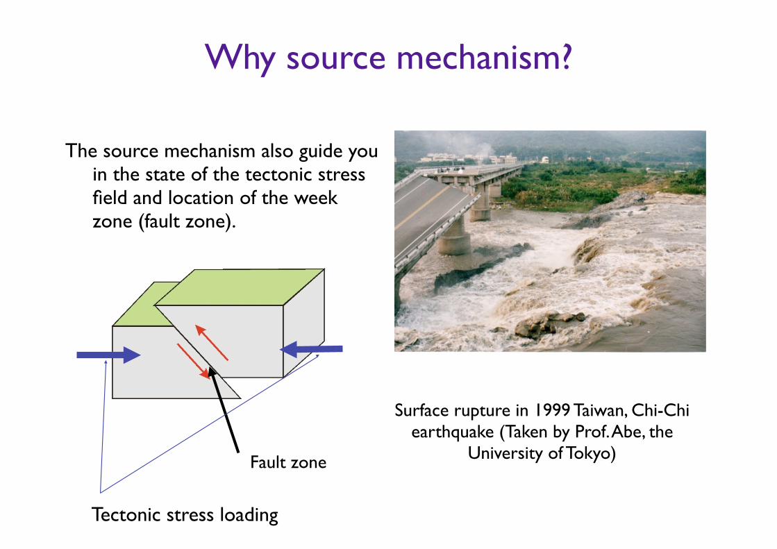
Why source mechanism?
The source mechanism also guide you in the state of the tectonic stress field and location of the week zone (fault zone).
Surface rupture in 1999 Taiwan, Chi-Chi earthquake (Taken by Prof. Abe, the
University of Tokyo)Fault zone
Tectonic stress loading
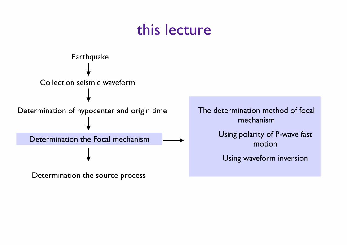
this lecture
Determination the Focal mechanism
Determination the source process
Earthquake
Collection seismic waveform
The determination method of focal mechanism
Using polarity of P-wave fast motion
Using waveform inversion
Determination of hypocenter and origin time
Terms and Fault Plane Parameters
Faulting can be classified three type.
1) Strike Slip faulting (right- and left-lateral)
2) Normal faulting
3) Reverse faulting
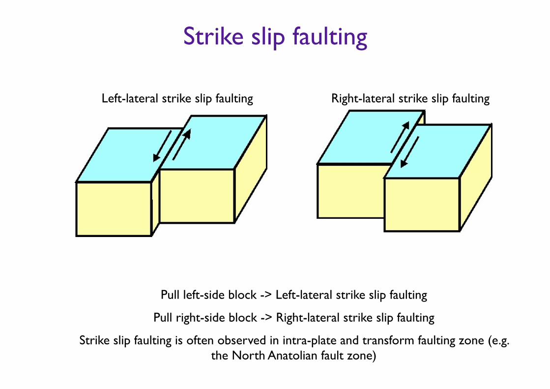
Strike slip faulting
Left-lateral strike slip faulting Right-lateral strike slip faulting
Pull left-side block -> Left-lateral strike slip faulting
Pull right-side block -> Right-lateral strike slip faulting
Strike slip faulting is often observed in intra-plate and transform faulting zone (e.g. the North Anatolian fault zone)
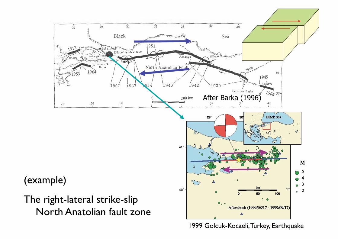
(example)
The right-lateral strike-slip North Anatolian fault zone
1999 Golcuk-Kocaeli, Turkey, Earthquake
After Barka (1996)
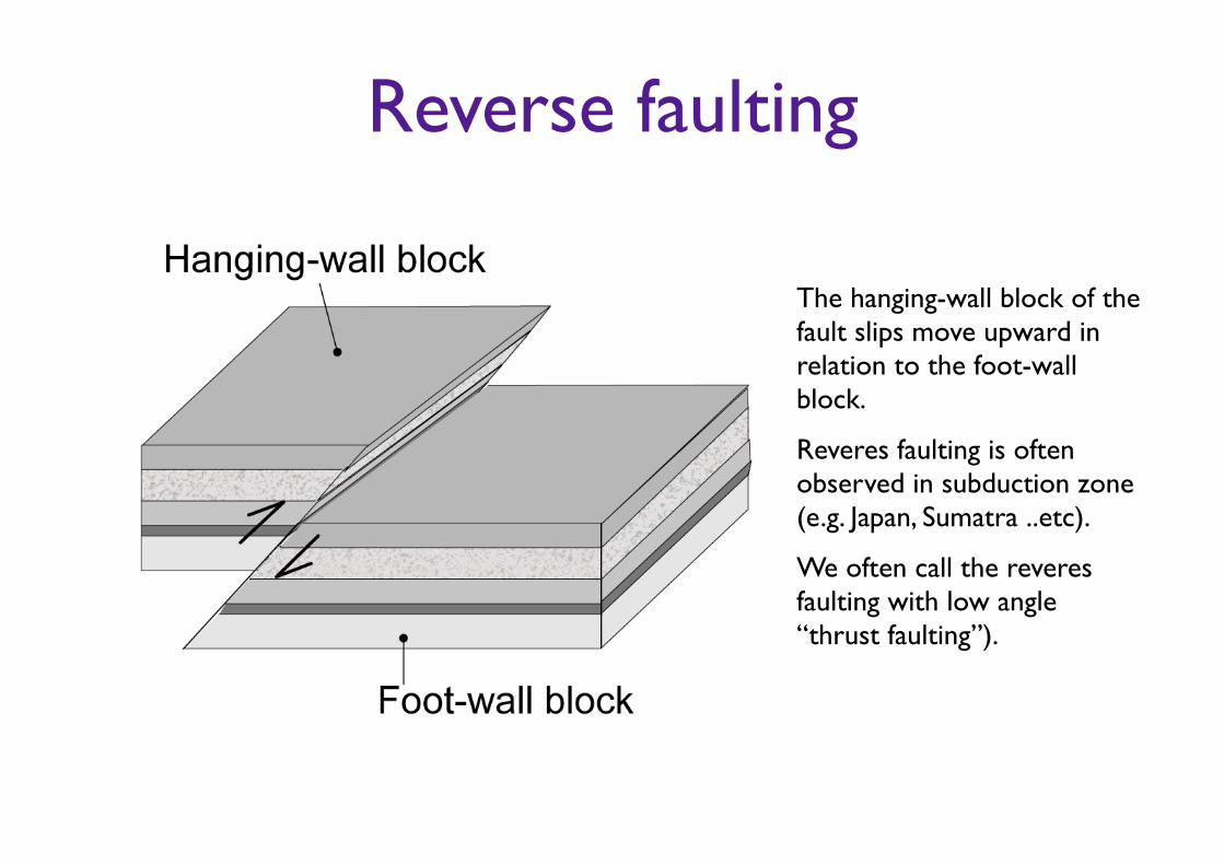
Reverse faulting
The hanging-wall block of the fault slips move upward in relation to the foot-wall block.
Reveres faulting is often observed in subduction zone (e.g. Japan, Sumatra ..etc).
We often call the reveres faulting with low angle “thrust faulting”).
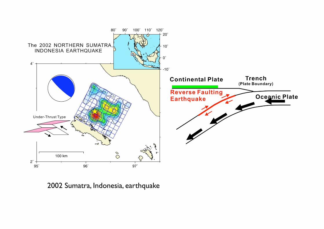
2002 Sumatra, Indonesia, earthquake
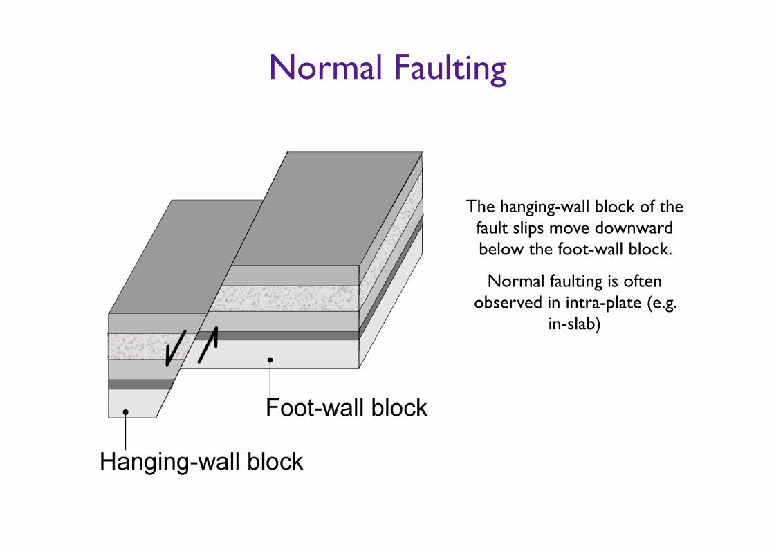
Normal Faulting
The hanging-wall block of the fault slips move downward below the foot-wall block.
Normal faulting is often observed in intra-plate (e.g.
in-slab)
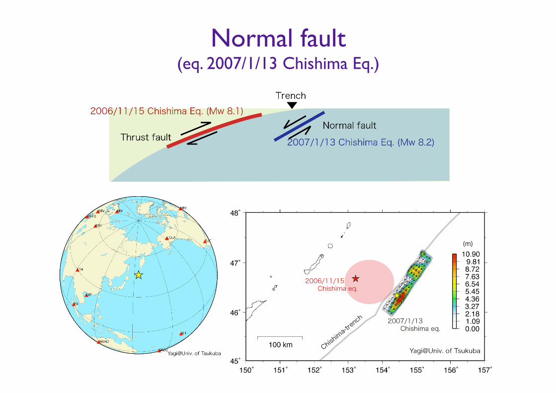
Normal fault(eq. 2007/1/13 Chishima Eq.)
Fault plane parameters
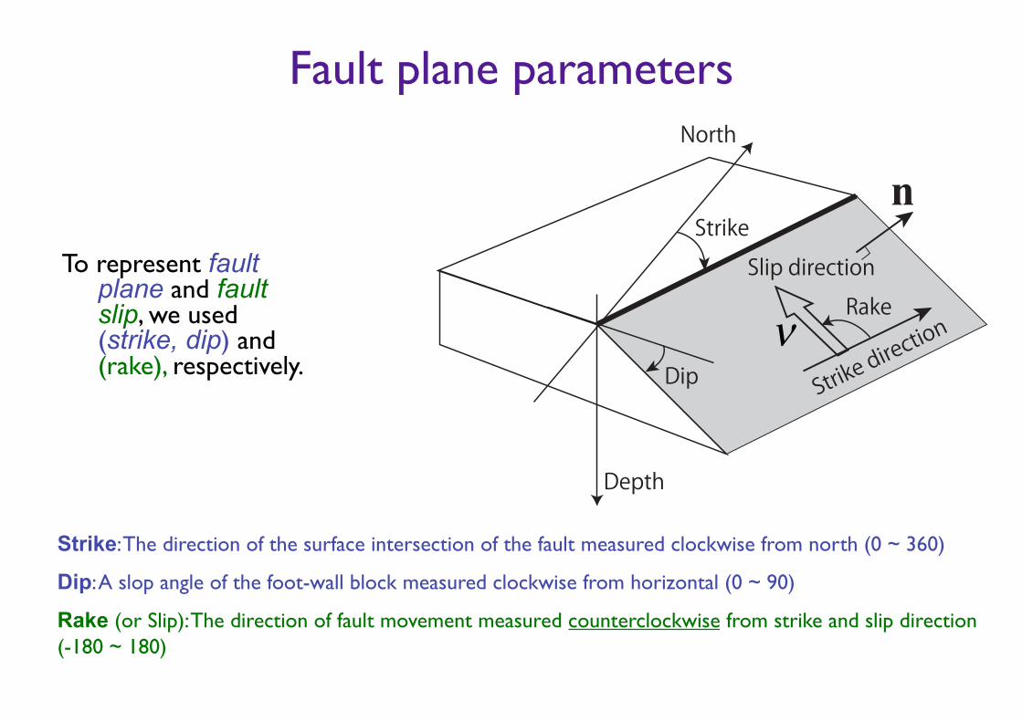
To represent fault plane and fault slip, we used (strike, dip) and (rake), respectively.
Strike: The direction of the surface intersection of the fault measured clockwise from north (0 ~ 360)
Dip: A slop angle of the foot-wall block measured clockwise from horizontal (0 ~ 90)
Rake (or Slip): The direction of fault movement measured counterclockwise from strike and slip direction (-180 ~ 180)
n
Strike direc
tion
Slip directionRake
Strike
Dip
North
Depth
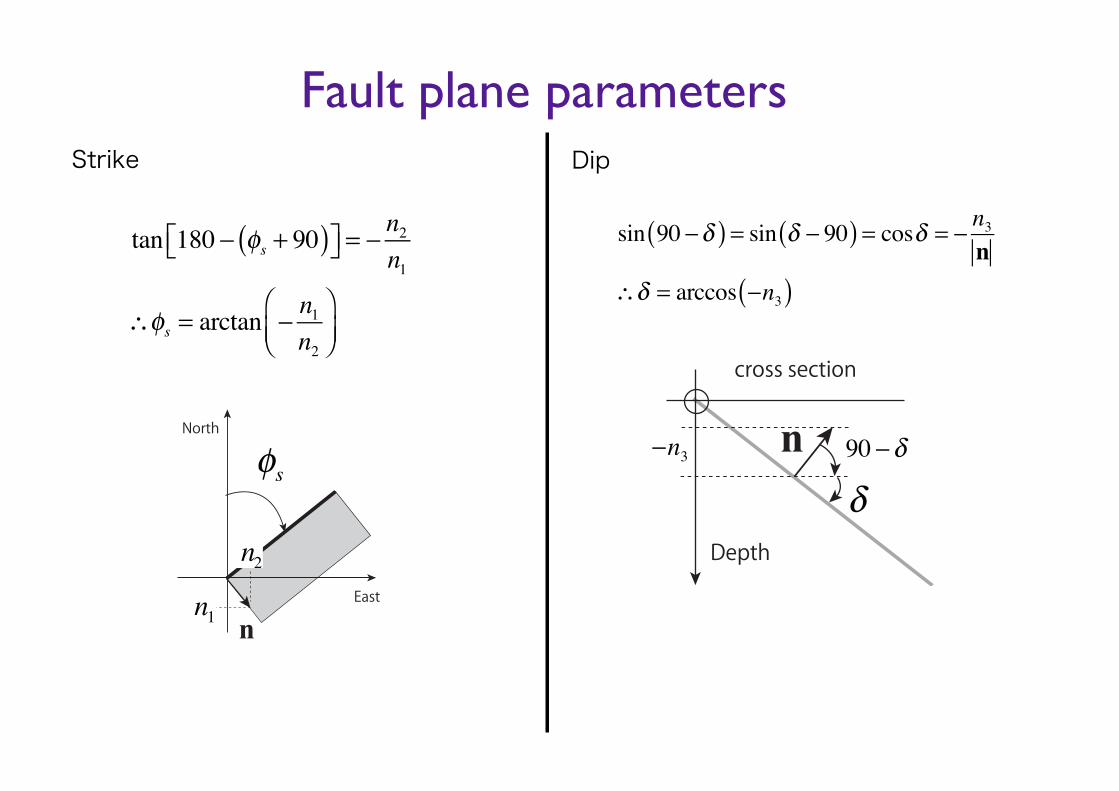
Fault plane parametersStrike
s
n1
n2
n
North
East
tan 180 − φs + 90( )⎡⎣ ⎤⎦ = − n2n1
∴φs = arctan − n1n2
⎛⎝⎜
⎞⎠⎟
sin 90 −δ( ) = sin δ − 90( ) = cosδ = − n3n
∴δ = arccos −n3( )
n
Depth
cross section
90n3
Dip
Fault plane parameters
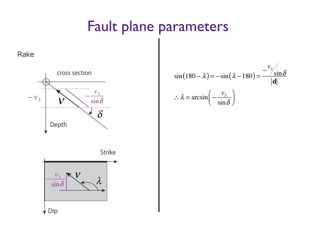
Rake
sin 180 − λ( ) = −sin λ −180( ) =−v3 sinδd
∴λ = arcsin − v3sinδ
⎛⎝⎜
⎞⎠⎟
Depth
cross section
v3sinv3
Strike
Dip
v3sin
Fault plane parameters
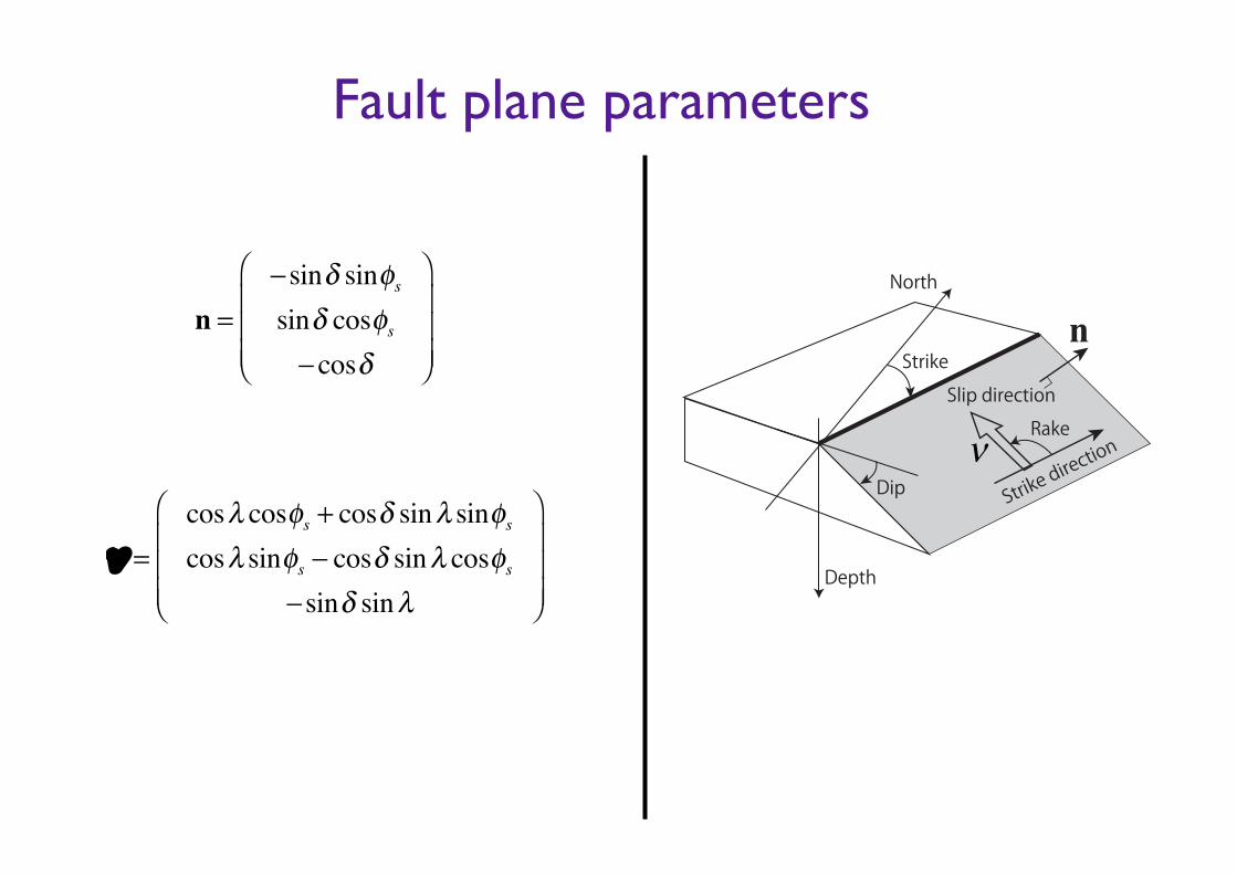
n =−sinδ sinφssinδ cosφs−cosδ
⎛
⎝
⎜⎜⎜
⎞
⎠
⎟⎟⎟
ν =cosλ cosφs + cosδ sinλ sinφscosλ sinφs − cosδ sinλ cosφs
−sinδ sinλ
⎛
⎝
⎜⎜⎜
⎞
⎠
⎟⎟⎟
n
Strike direc
tion
Slip directionRake
Strike
Dip
North
Depth
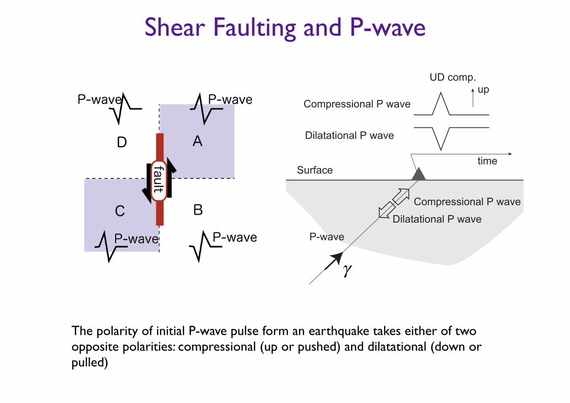
Shear Faulting and P-wave
The polarity of initial P-wave pulse form an earthquake takes either of two opposite polarities: compressional (up or pushed) and dilatational (down or pulled)
Surface
P-wave
Compressional P wave
Dilatational P wave
time
Compressional P wave
Dilatational P wave
upUD comp.
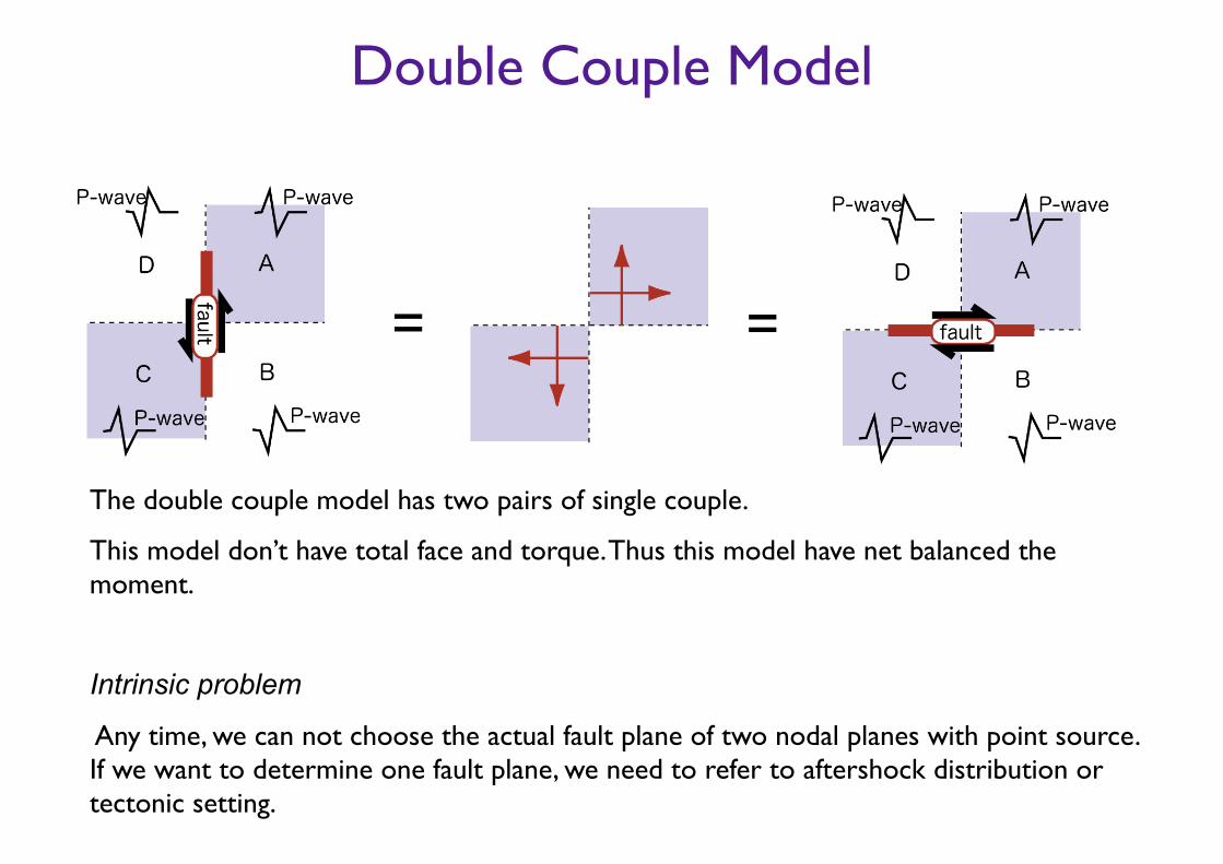
Double Couple Model
The double couple model has two pairs of single couple.
This model don’t have total face and torque. Thus this model have net balanced the moment.
!Intrinsic problem
Any time, we can not choose the actual fault plane of two nodal planes with point source. If we want to determine one fault plane, we need to refer to aftershock distribution or tectonic setting.
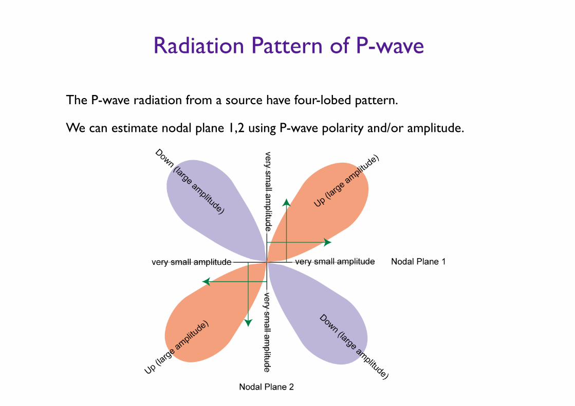
Radiation Pattern of P-wave
The P-wave radiation from a source have four-lobed pattern.
We can estimate nodal plane 1,2 using P-wave polarity and/or amplitude.
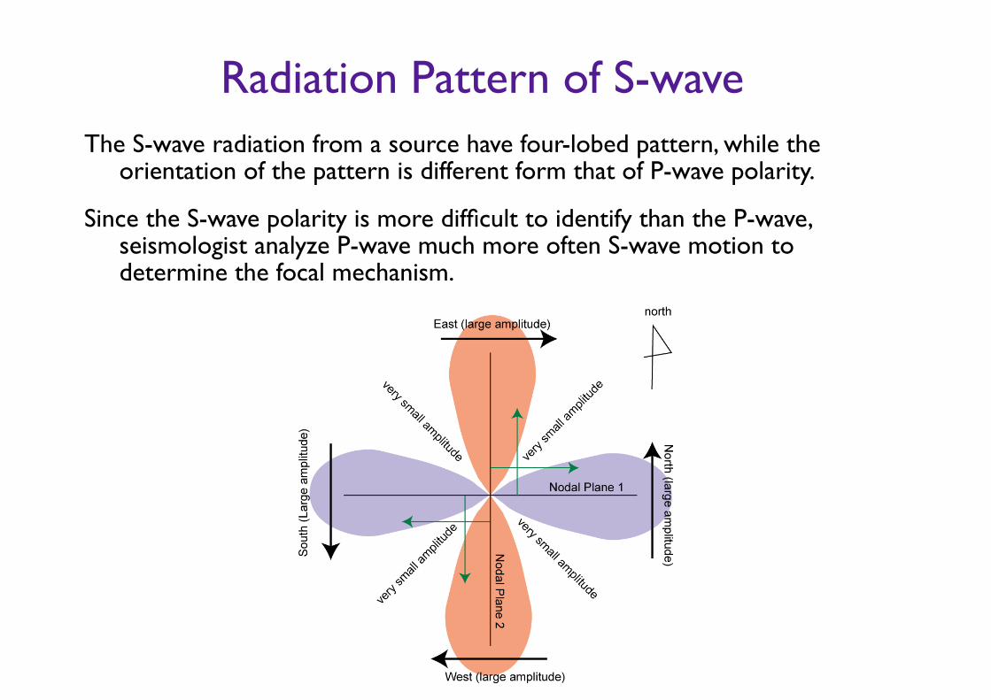
Radiation Pattern of S-waveThe S-wave radiation from a source have four-lobed pattern, while the
orientation of the pattern is different form that of P-wave polarity.
Since the S-wave polarity is more difficult to identify than the P-wave, seismologist analyze P-wave much more often S-wave motion to determine the focal mechanism.
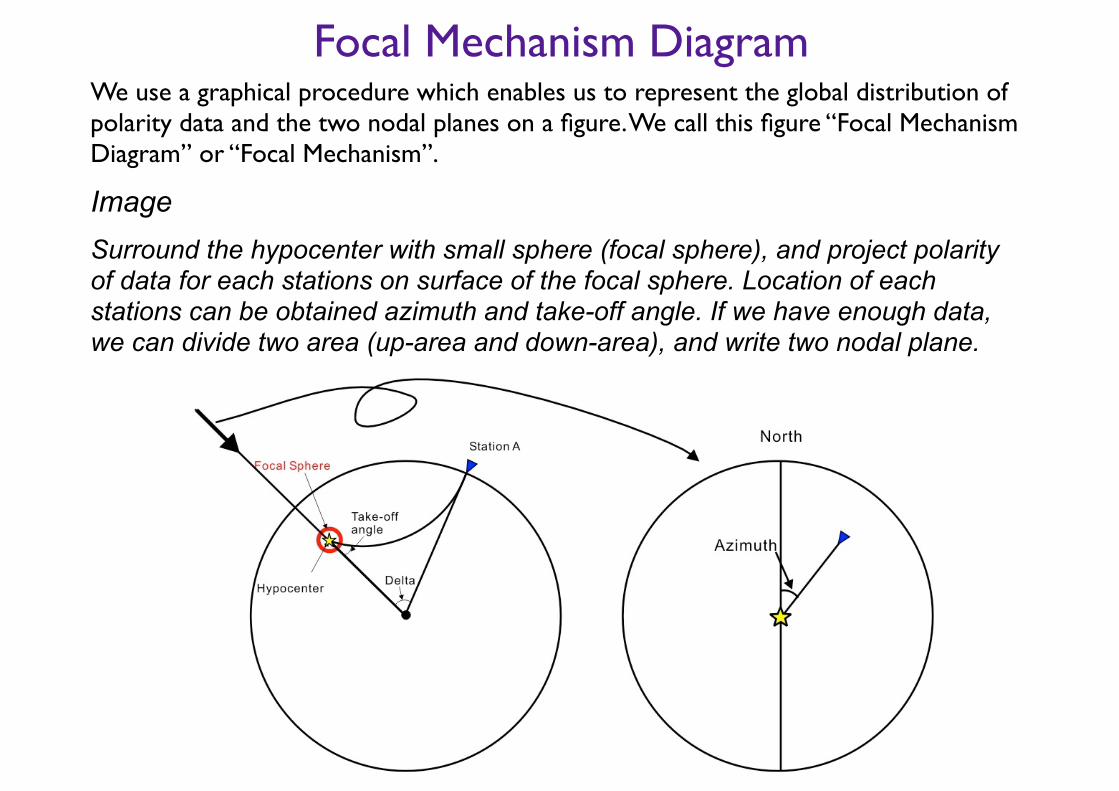
Focal Mechanism DiagramWe use a graphical procedure which enables us to represent the global distribution of polarity data and the two nodal planes on a figure. We call this figure “Focal Mechanism Diagram” or “Focal Mechanism”.
Image Surround the hypocenter with small sphere (focal sphere), and project polarity of data for each stations on surface of the focal sphere. Location of each stations can be obtained azimuth and take-off angle. If we have enough data, we can divide two area (up-area and down-area), and write two nodal plane.

Focal Mechanism DiagramThe focal sphere is three-dimensional body, so the polarity data on the sphere is
three dimensional data on a two-dimensional diagram.
We projection of focal sphere onto a equatorial plane.
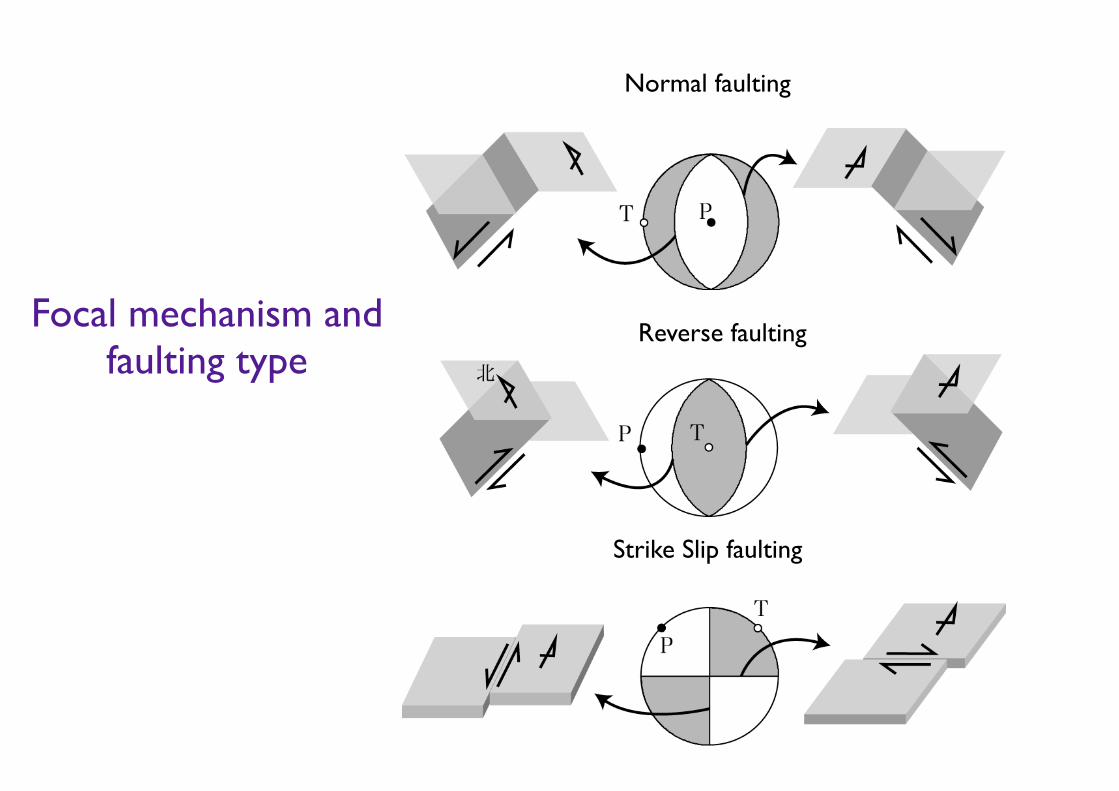
Focal mechanism and faulting type
Normal faulting
Strike Slip faulting
Reverse faulting
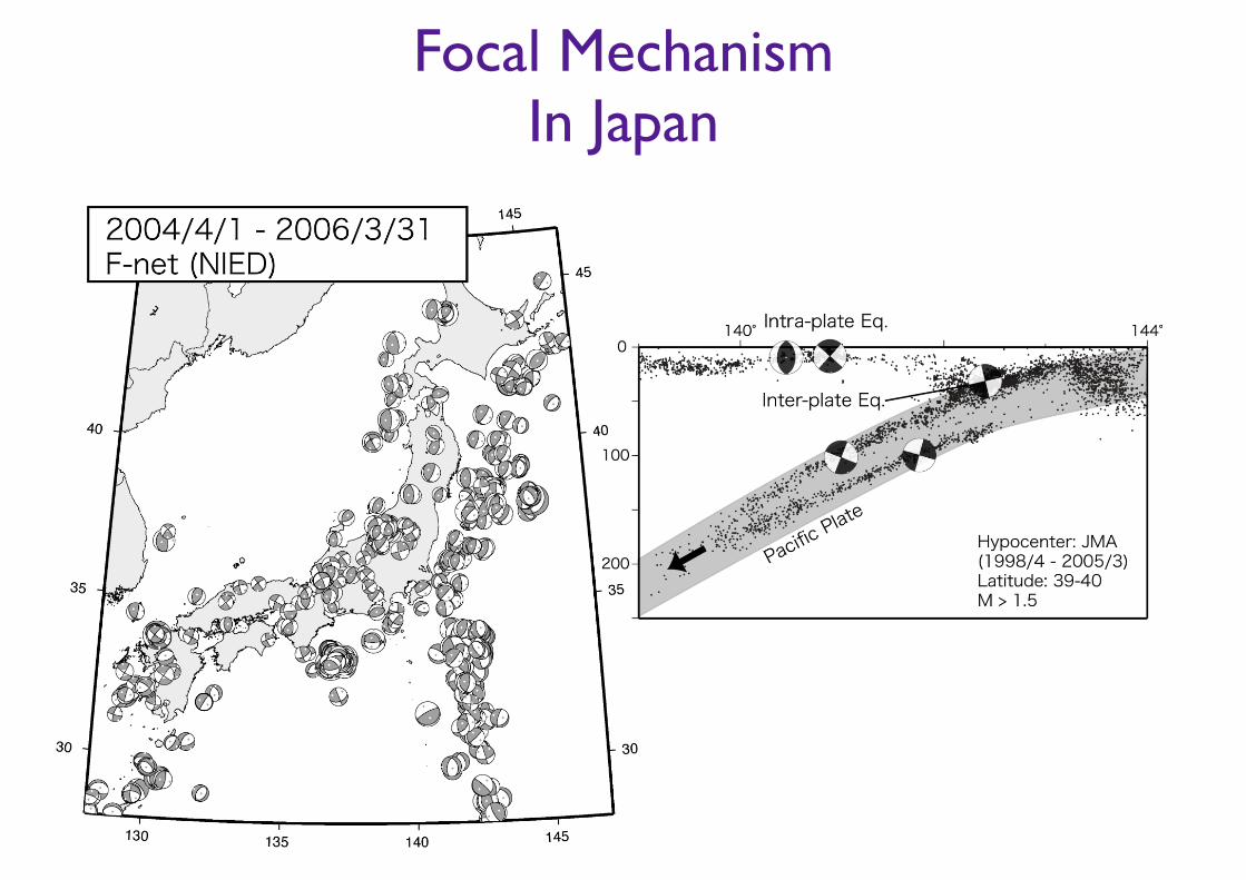
Focal Mechanism In Japan
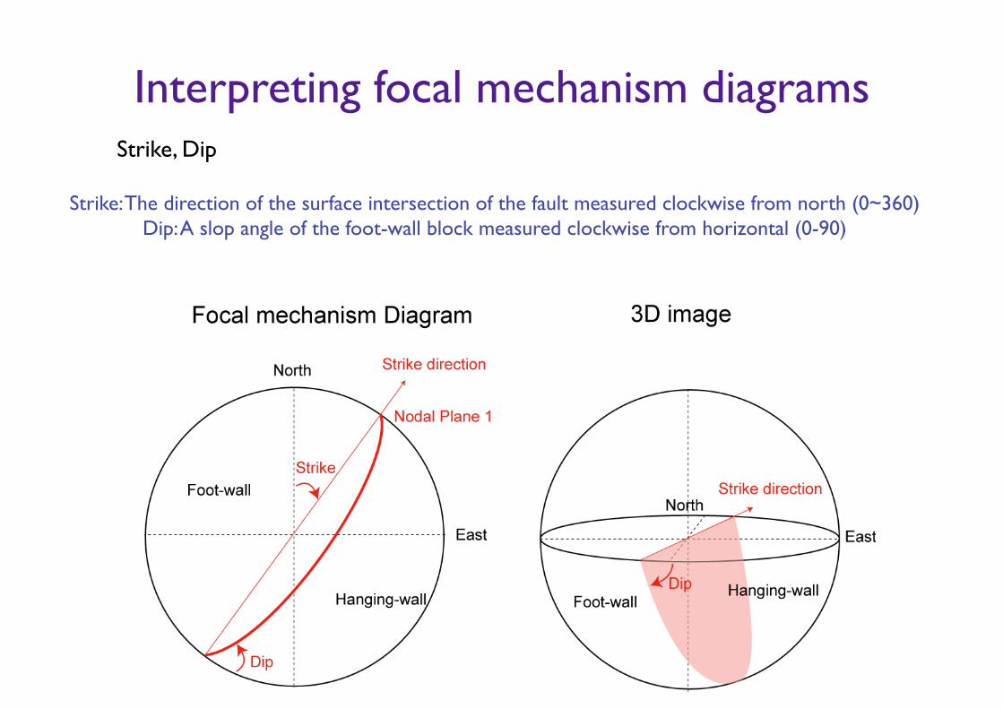
Interpreting focal mechanism diagramsStrike, Dip
Strike: The direction of the surface intersection of the fault measured clockwise from north (0~360) Dip: A slop angle of the foot-wall block measured clockwise from horizontal (0-90)
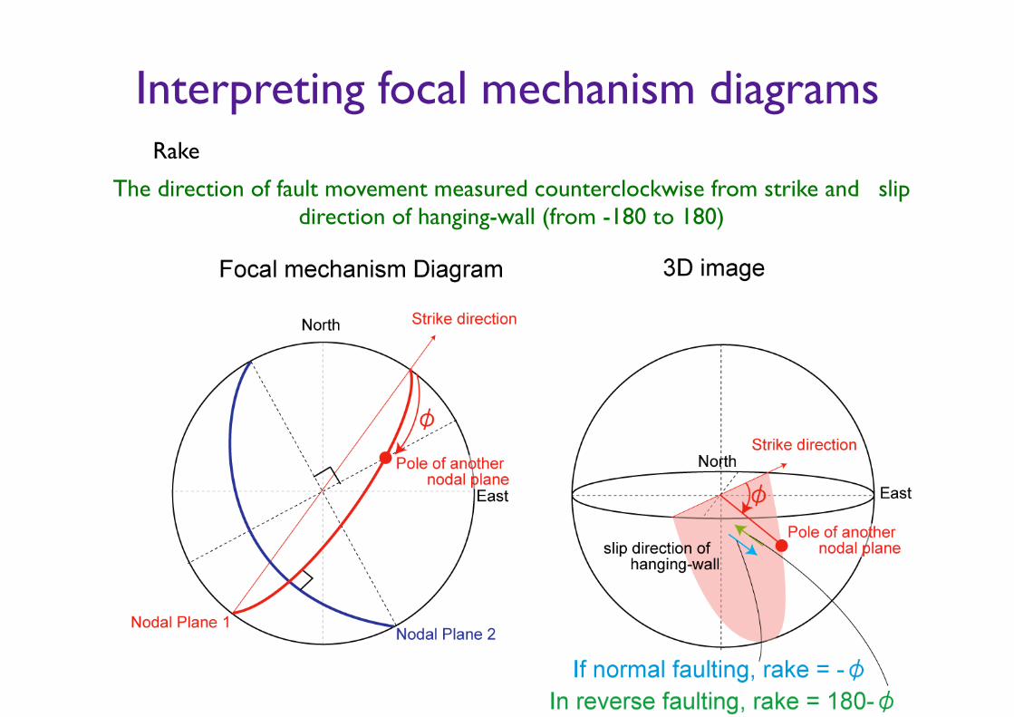
Interpreting focal mechanism diagramsRake
The direction of fault movement measured counterclockwise from strike and slip direction of hanging-wall (from -180 to 180)

Method of focal mechanism determination
For Single event • Using polarity of first P-wave.
Requirement: many stations (depend on station coverage)
• Using polarity and amplitude of first P-wave.
Requirement: Five or more P-wave components
• Using waveform of P-wave and S-wave.
Requirement: Five or more waveform components
• Using overall waveform.
Requirement: One or more waveform stations.
Determining Fault Plane Solution using polarity of P-wave
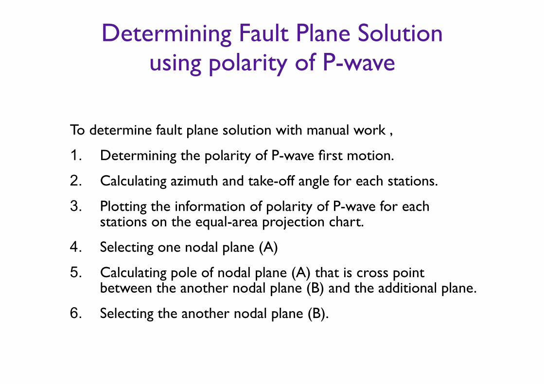
To determine fault plane solution with manual work ,
1. Determining the polarity of P-wave first motion.
2. Calculating azimuth and take-off angle for each stations.
3. Plotting the information of polarity of P-wave for each stations on the equal-area projection chart.
4. Selecting one nodal plane (A)
5. Calculating pole of nodal plane (A) that is cross point between the another nodal plane (B) and the additional plane.
6. Selecting the another nodal plane (B).
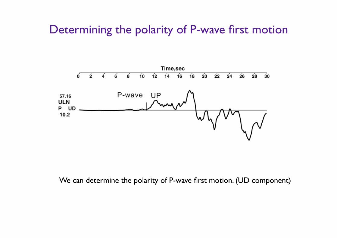
Determining the polarity of P-wave first motion
We can determine the polarity of P-wave first motion. (UD component)
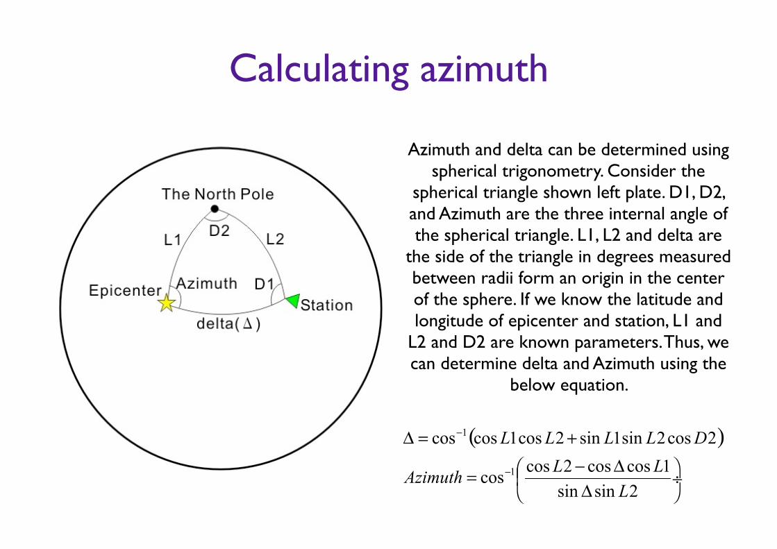
Calculating azimuth
Azimuth and delta can be determined using spherical trigonometry. Consider the
spherical triangle shown left plate. D1, D2, and Azimuth are the three internal angle of the spherical triangle. L1, L2 and delta are
the side of the triangle in degrees measured between radii form an origin in the center of the sphere. If we know the latitude and longitude of epicenter and station, L1 and
L2 and D2 are known parameters. Thus, we can determine delta and Azimuth using the
below equation.
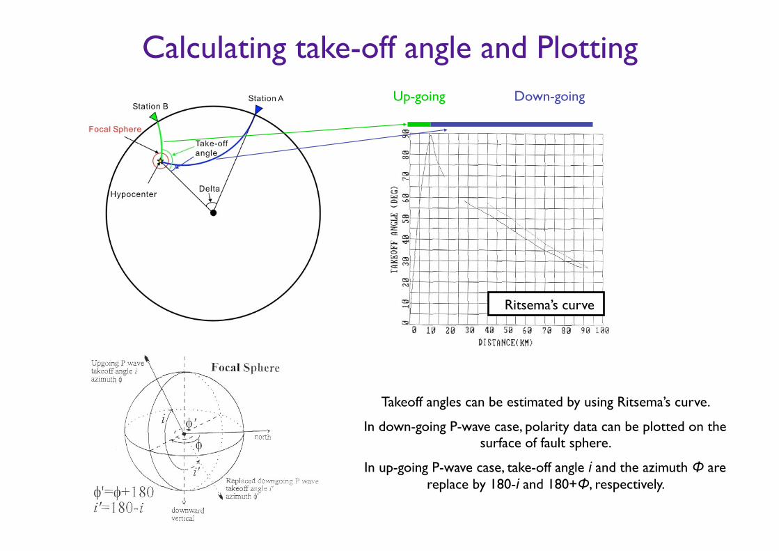
Calculating take-off angle and Plotting Up-going Down-going
Takeoff angles can be estimated by using Ritsema’s curve.
In down-going P-wave case, polarity data can be plotted on the surface of fault sphere.
In up-going P-wave case, take-off angle i and the azimuth Φ are replace by 180-i and 180+Φ, respectively.
Ritsema’s curve
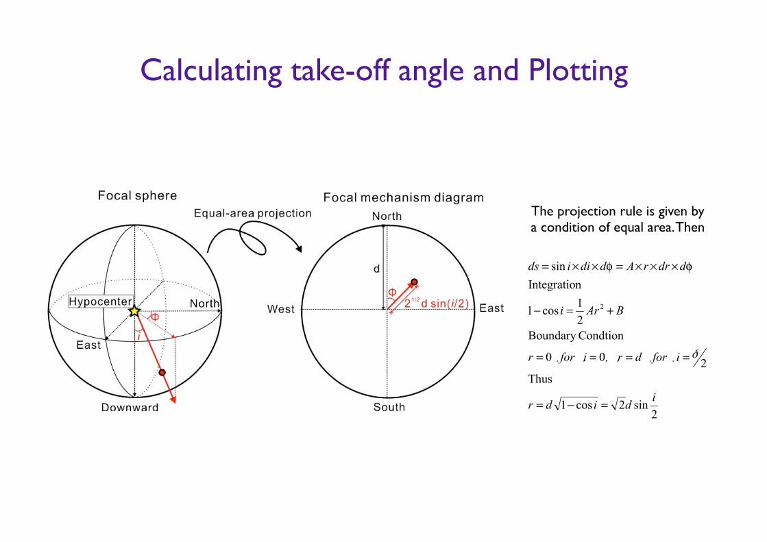
Calculating take-off angle and Plotting
The projection rule is given by a condition of equal area. Then
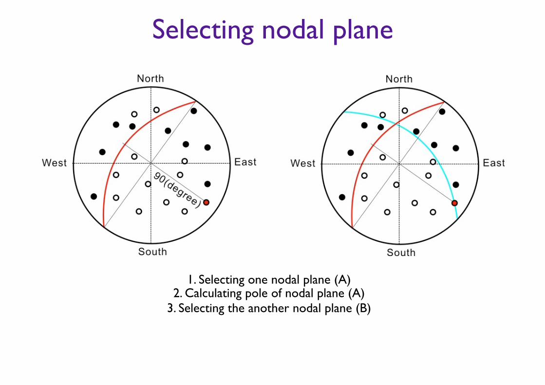
Selecting nodal plane
1. Selecting one nodal plane (A) 2. Calculating pole of nodal plane (A)
3. Selecting the another nodal plane (B)
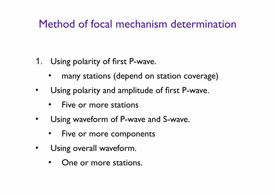
Method of focal mechanism determination
1. Using polarity of first P-wave.
• many stations (depend on station coverage)
• Using polarity and amplitude of first P-wave.
• Five or more stations
• Using waveform of P-wave and S-wave.
• Five or more components
• Using overall waveform.
• One or more stations.
Method of focal mechanism determination
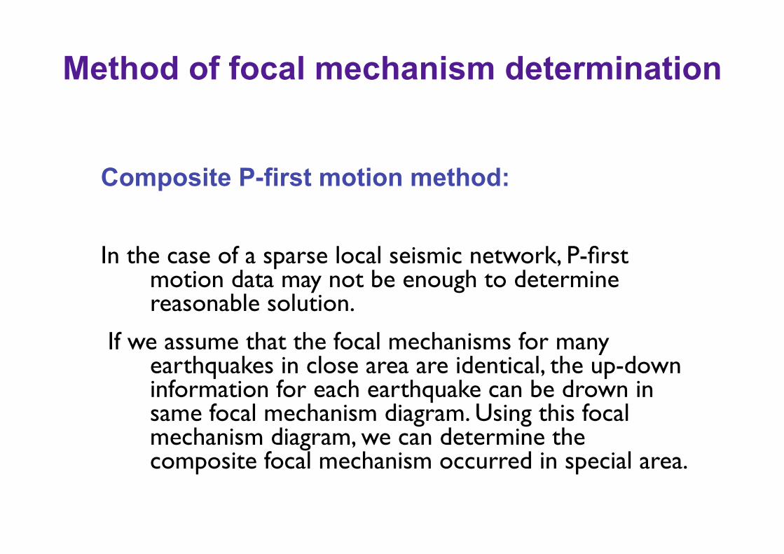
Composite P-first motion method: !In the case of a sparse local seismic network, P-first
motion data may not be enough to determine reasonable solution.
If we assume that the focal mechanisms for many earthquakes in close area are identical, the up-down information for each earthquake can be drown in same focal mechanism diagram. Using this focal mechanism diagram, we can determine the composite focal mechanism occurred in special area.
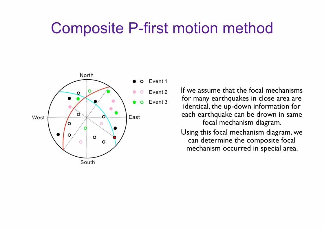
Composite P-first motion method
If we assume that the focal mechanisms for many earthquakes in close area are identical, the up-down information for each earthquake can be drown in same
focal mechanism diagram. Using this focal mechanism diagram, we
can determine the composite focal mechanism occurred in special area.
Moment Tensor Inversion
Yuji Yagi
(University of Tsukuba)
Introduction
Now, we can compute synthetic seismograms that are comparable with observed seismograms.
!The seismic waveforms contain the information of the
focal mechanism and seismic slip area.
!If we assume earth structure, we can calculate green’s
function and estimate moment tensor components and location of centroid using waveform inversion scheme.
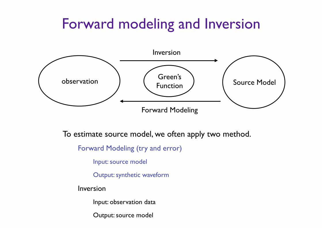
Forward modeling and Inversion
To estimate source model, we often apply two method.
Forward Modeling (try and error)
Input: source model
Output: synthetic waveform
Inversion
Input: observation data
Output: source model
observation Source Model Green’s Function
Inversion
Forward Modeling
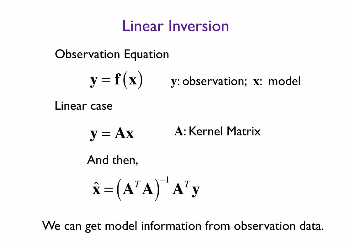
Linear Inversion
Observation Equation
y = f x( ) y: observation; x: model
Linear case
y = Ax A: Kernel Matrix
x̂ = ATA( )−1ATy
And then,
We can get model information from observation data.
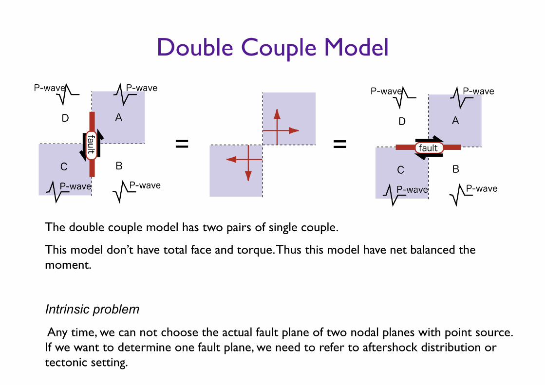
Double Couple Model
The double couple model has two pairs of single couple.
This model don’t have total face and torque. Thus this model have net balanced the moment.
!Intrinsic problem
Any time, we can not choose the actual fault plane of two nodal planes with point source. If we want to determine one fault plane, we need to refer to aftershock distribution or tectonic setting.
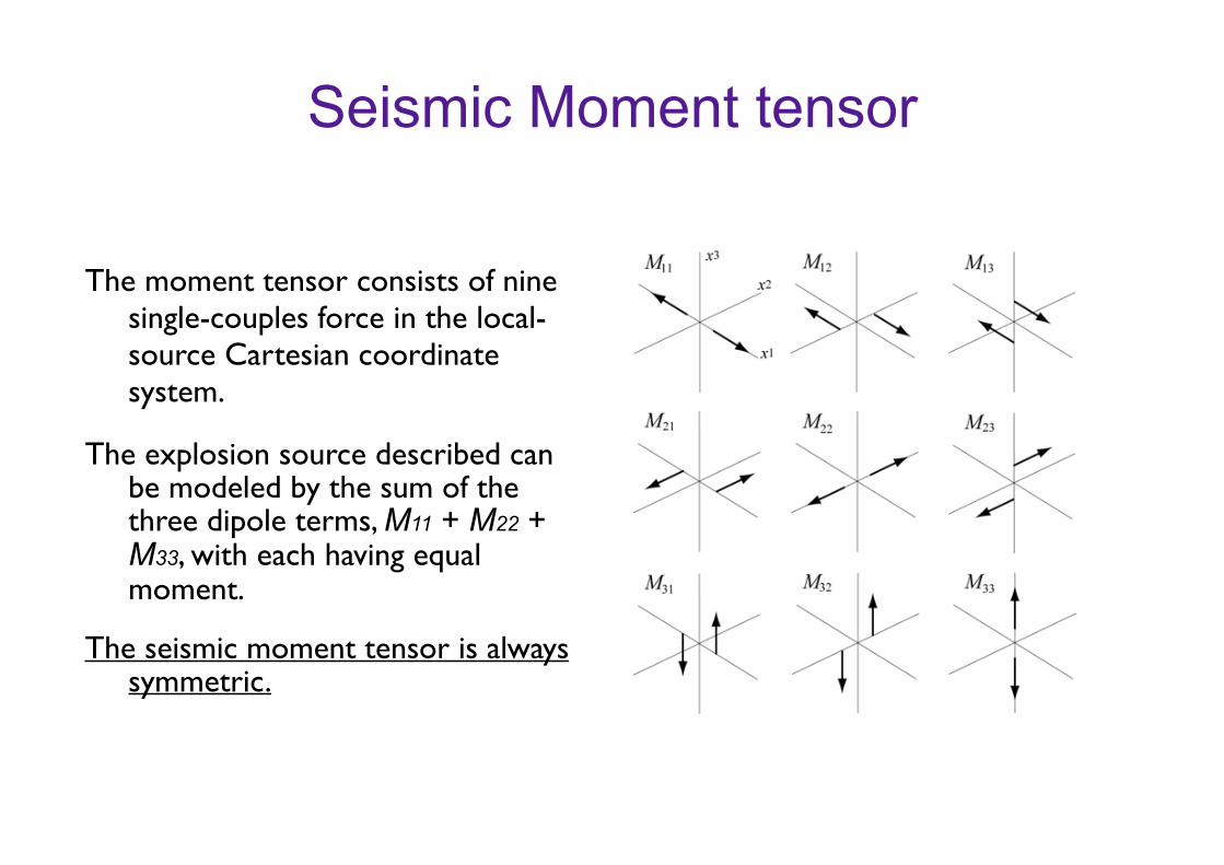
Seismic Moment tensor
The moment tensor consists of nine single-couples force in the local-source Cartesian coordinate system.
The explosion source described can be modeled by the sum of the three dipole terms, M11 + M22 + M33, with each having equal moment.
The seismic moment tensor is always symmetric.
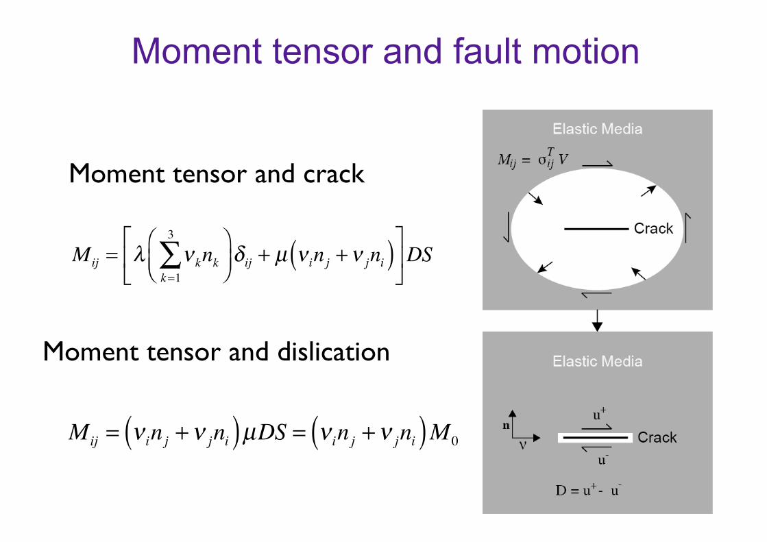
Moment tensor and fault motion
Mij = λ νknkk=1
3
∑⎛⎝⎜⎞⎠⎟δ ij + µ ν in j + ν jni( )⎡
⎣⎢
⎤
⎦⎥DS
Mij = ν in j + ν jni( )µDS = ν in j + ν jni( )M 0
Moment tensor and crack
Moment tensor and dislication
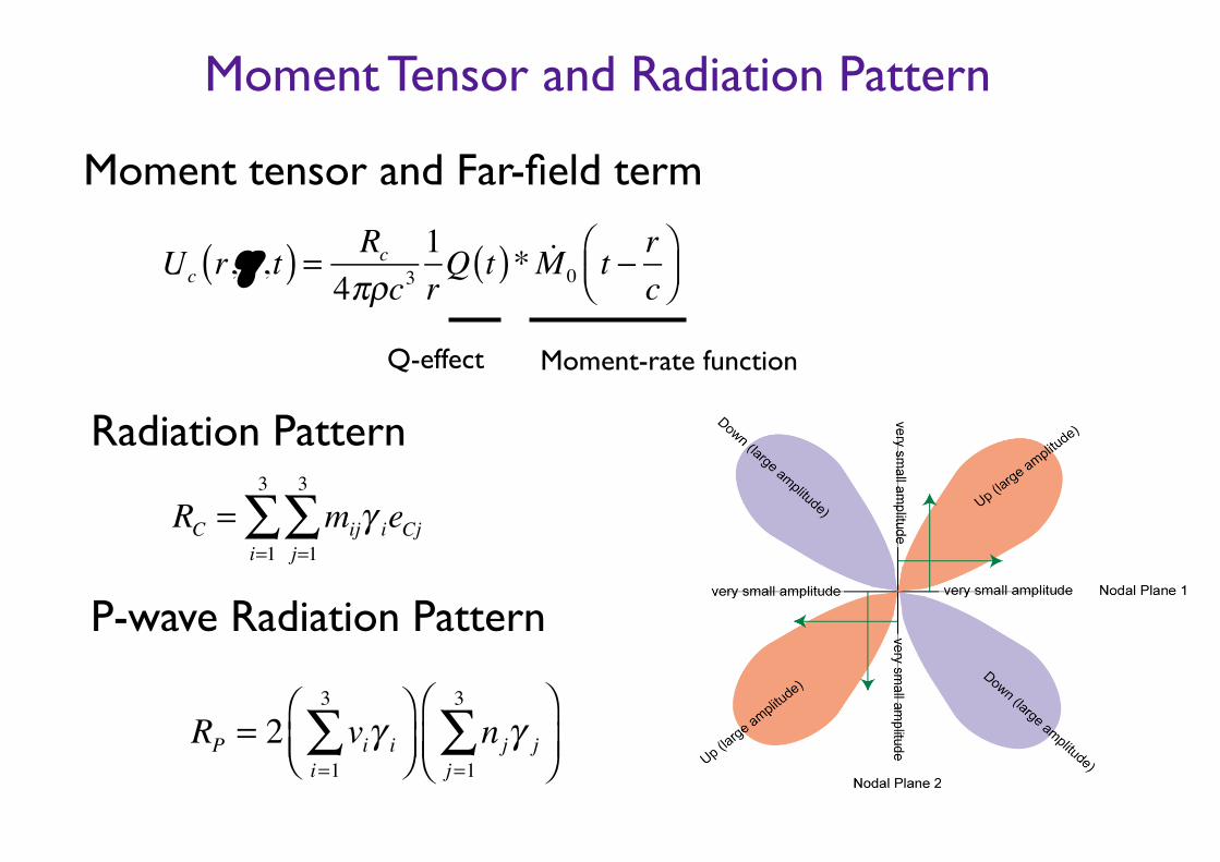
Moment tensor and Far-field term
Uc r,γ ,t( ) = Rc
4πρc31rQ t( )* !M 0 t − r
c⎛⎝⎜
⎞⎠⎟
RC = mijγ ieCjj=1
3
∑i=1
3
∑
Radiation Pattern
RP = 2 viγ ii=1
3
∑⎛⎝⎜⎞⎠⎟
njγ jj=1
3
∑⎛
⎝⎜⎞
⎠⎟
P-wave Radiation Pattern
Moment Tensor and Radiation Pattern
Q-effect Moment-rate function
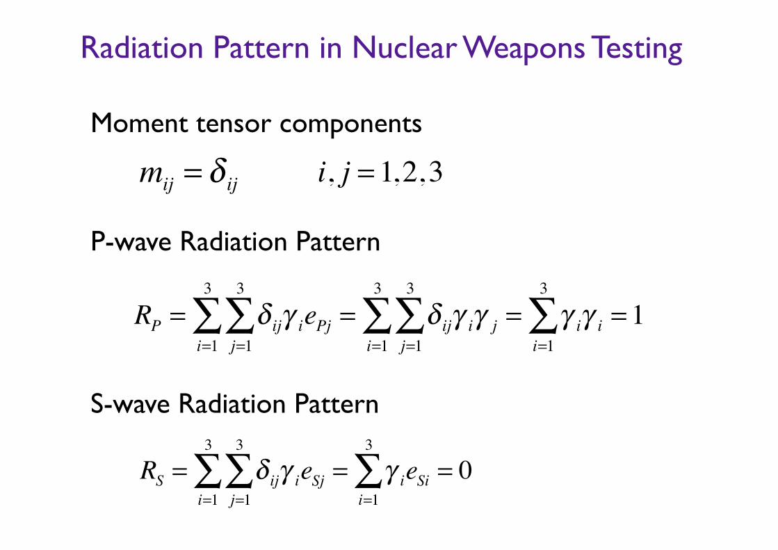
Moment tensor components
Radiation Pattern in Nuclear Weapons Testing
RP = δ ijγ iePjj=1
3
∑i=1
3
∑ = δ ijγ iγ jj=1
3
∑i=1
3
∑ = γ iγ ii=1
3
∑ = 1
mij = δ ij i, j = 1,2,3
RS = δ ijγ ieSjj=1
3
∑i=1
3
∑ = γ ieSii=1
3
∑ = 0
P-wave Radiation Pattern
S-wave Radiation Pattern
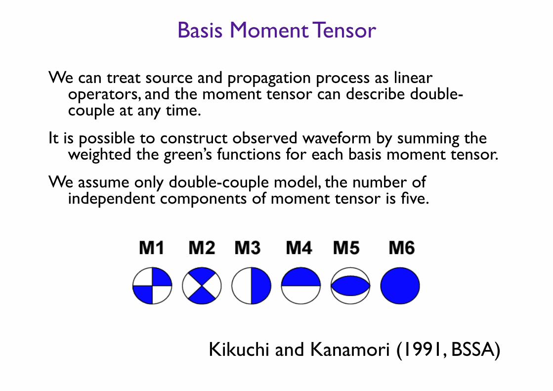
We can treat source and propagation process as linear operators, and the moment tensor can describe double-couple at any time.
It is possible to construct observed waveform by summing the weighted the green’s functions for each basis moment tensor.
We assume only double-couple model, the number of independent components of moment tensor is five.
Kikuchi and Kanamori (1991, BSSA)
Basis Moment Tensor
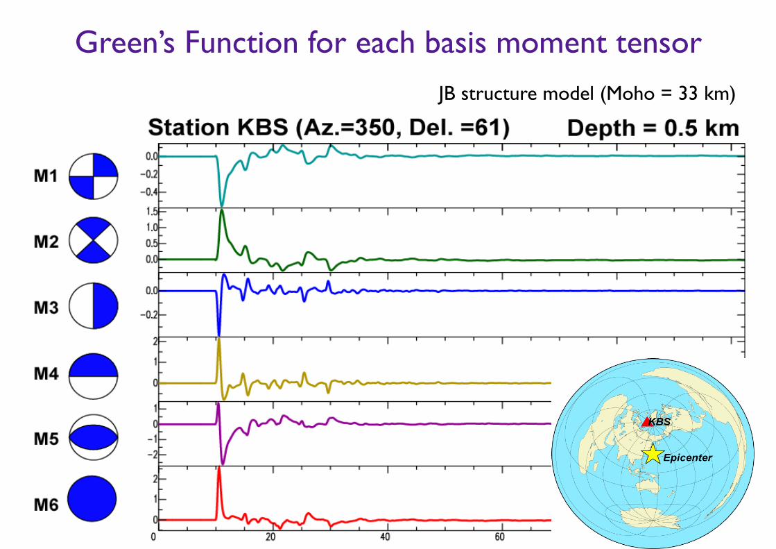
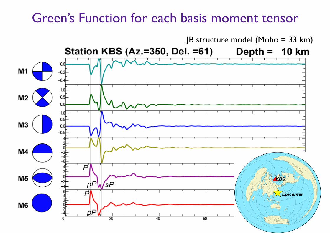
JB structure model (Moho = 33 km)
Green’s Function for each basis moment tensor
JB structure model (Moho = 33 km)
Green’s Function for each basis moment tensor
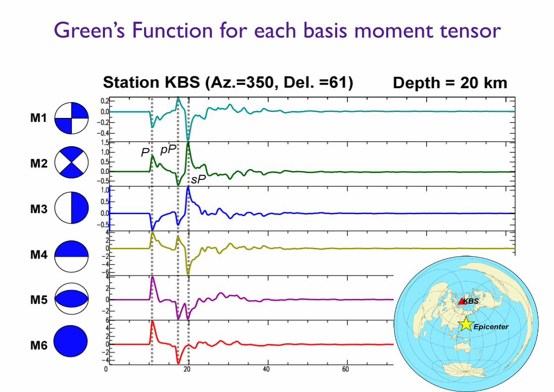
Green’s Function for each basis moment tensor
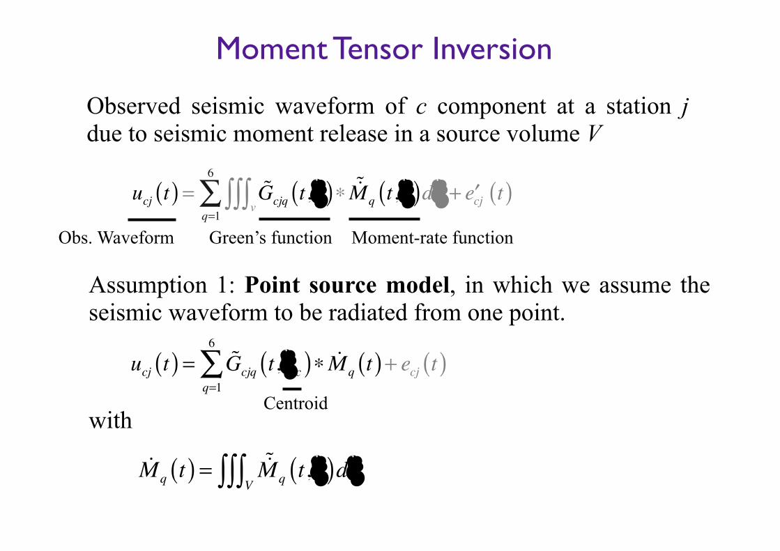
Observed seismic waveform of c component at a station j due to seismic moment release in a source volume V
ucj t( ) = !Gcjq t,ξ( )∗ !"Mq t,ξ( )dξv∫∫∫
q=1
6
∑ + ′ecj t( )
Assumption 1: Point source model, in which we assume the seismic waveform to be radiated from one point.
ucj t( ) = !Gcjq t,ξc( )∗ !Mq t( )q=1
6
∑ + ecj t( )
!Mq t( ) = !"Mq t,ξ( )dξV∫∫∫
withCentroid
Moment-rate function Green’s functionObs. Waveform
Moment Tensor Inversion
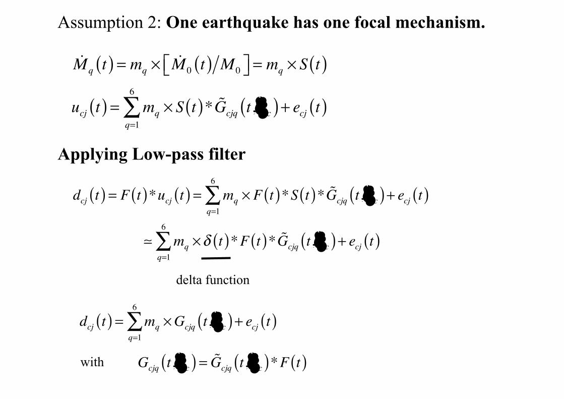
Assumption 2: One earthquake has one focal mechanism.
!Mq t( ) = mq × !M 0 t( ) M 0⎡⎣ ⎤⎦ = mq × S t( )
ucj t( ) = mq × S t( )* !Gcjq t,ξc( )q=1
6
∑ + ecj t( )
Applying Low-pass filter
dcj t( ) = F t( )*ucj t( ) = mq × F t( )*S t( )* !Gcjq t,ξc( )q=1
6
∑ + ecj t( )
! mq ×δ t( )*F t( )* !Gcjq t,ξc( )q=1
6
∑ + ecj t( )
delta function
dcj t( ) = mq ×Gcjq t,ξc( )q=1
6
∑ + ecj t( )
Gcjq t,ξc( ) = !Gcjq t,ξc( )*F t( )with
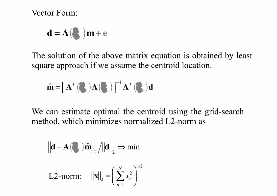
Vector Form:
d = A ξc( )m+ e
The solution of the above matrix equation is obtained by least square approach if we assume the centroid location.
d −A ξc( )m̂2d
2⇒min
We can estimate optimal the centroid using the grid-search method, which minimizes normalized L2-norm as
x 2 = xn2
n=1
N
∑⎛⎝⎜⎞⎠⎟
1/2
L2-norm:
m̂ = AT ξc( )A ξc( )⎡⎣ ⎤⎦−1AT ξc( )d
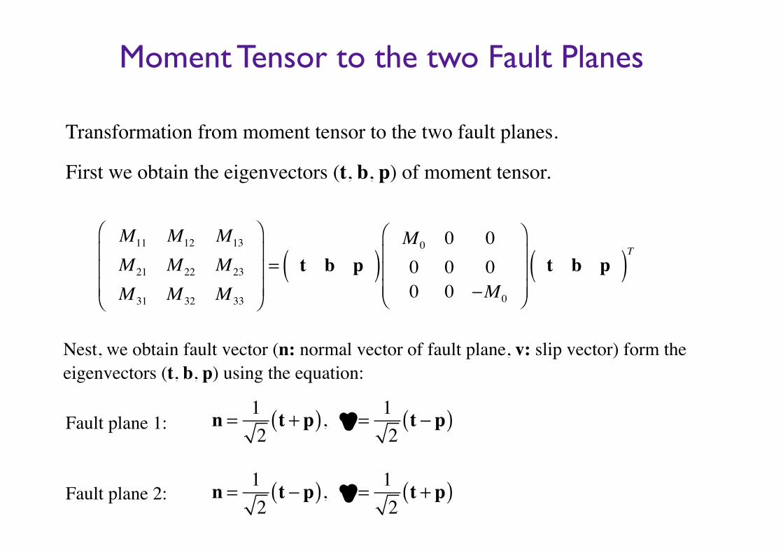
Moment Tensor to the two Fault Planes
Transformation from moment tensor to the two fault planes.
First we obtain the eigenvectors (t, b, p) of moment tensor.
Nest, we obtain fault vector (n: normal vector of fault plane, v: slip vector) form the eigenvectors (t, b, p) using the equation:
M11 M12 M13
M 21 M 22 M 23
M 31 M 32 M 33
⎛
⎝
⎜⎜⎜
⎞
⎠
⎟⎟⎟= t b p( )
M 0 0 00 0 00 0 −M 0
⎛
⎝
⎜⎜⎜
⎞
⎠
⎟⎟⎟t b p( )T
n = 12t + p( ), ν = 1
2t − p( )
n = 12t − p( ), ν = 1
2t + p( )
Fault plane 1:
!Fault plane 2:
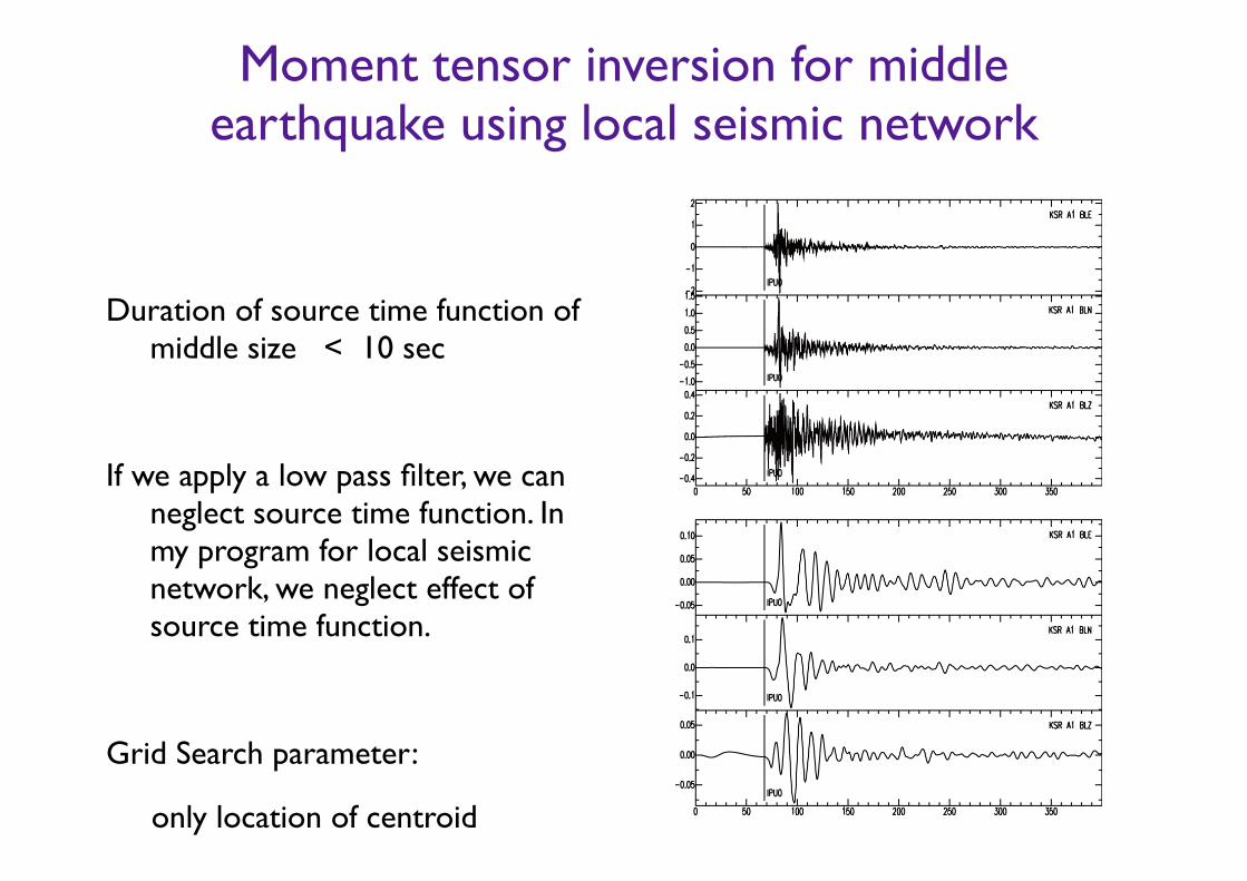
Moment tensor inversion for middle earthquake using local seismic network
Duration of source time function of middle size < 10 sec
!If we apply a low pass filter, we can
neglect source time function. In my program for local seismic network, we neglect effect of source time function.
!Grid Search parameter:
only location of centroid
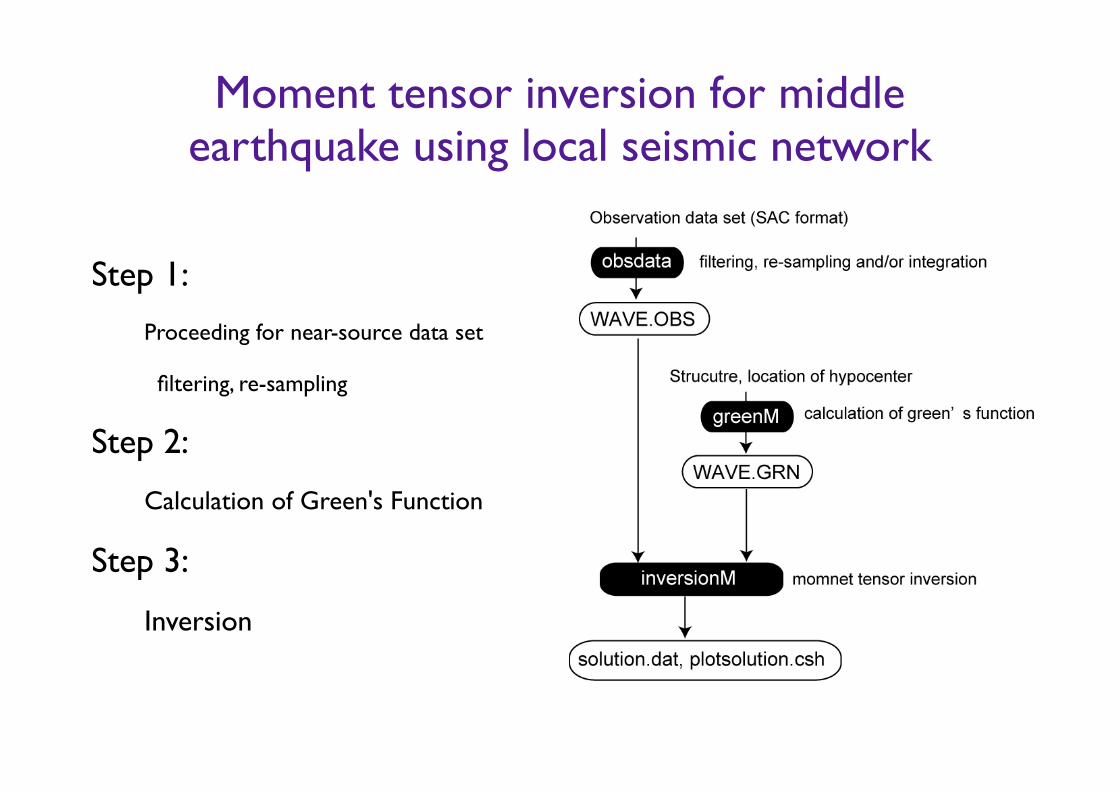
Moment tensor inversion for middle earthquake using local seismic network
Step 1:
Proceeding for near-source data set
filtering, re-sampling
Step 2:
Calculation of Green's Function
Step 3:
Inversion
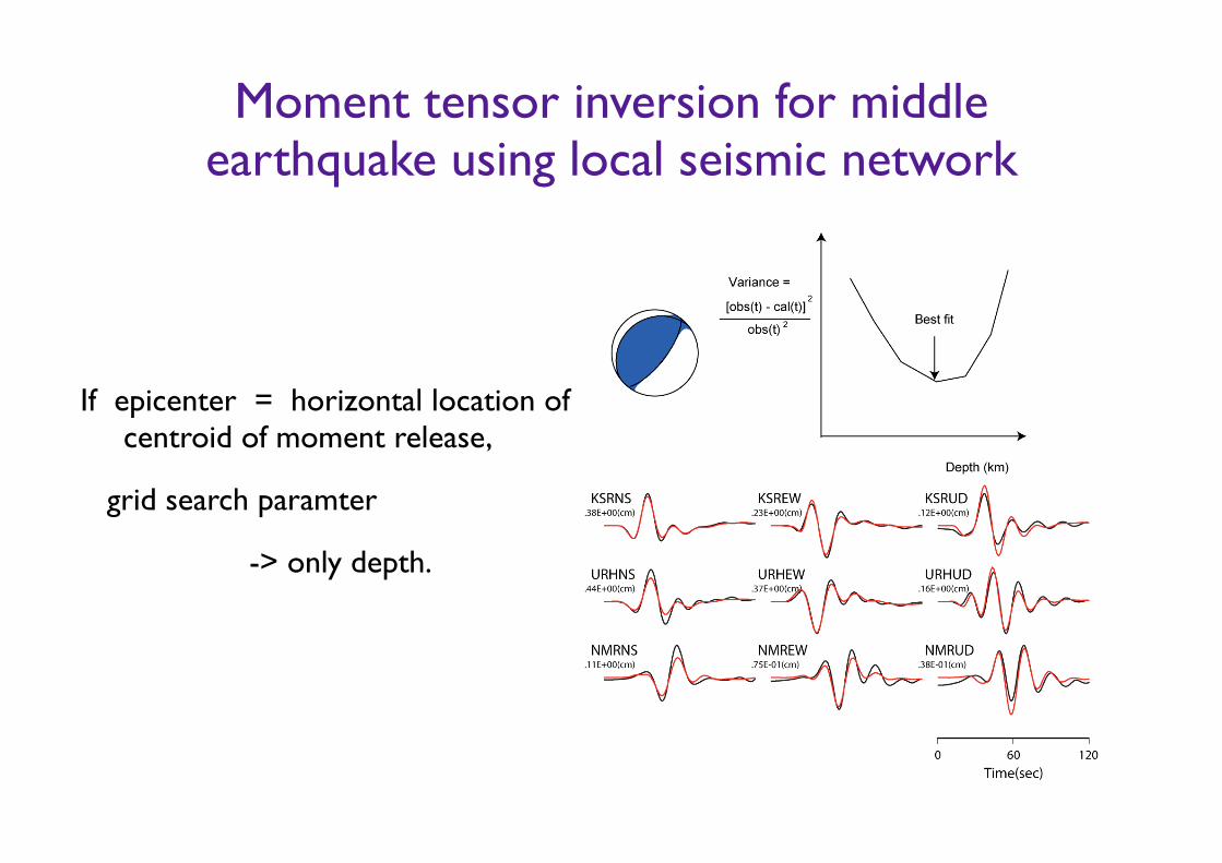
Moment tensor inversion for middle earthquake using local seismic network
If epicenter = horizontal location of centroid of moment release,
grid search paramter
-> only depth.