Scatter Loading -...
29
Open Access Application Note Scatter Loading Document number: ARM DAI 0048A Issued: January 1998 Copyright Advanced RISC Machines Ltd (ARM) 1998 ENGLAND Advanced RISC Machines Limited Fulbourn Road Cherry Hinton Cambridge CB1 4JN UK Telephone: +44 1223 400400 Facsimile: +44 1223 400410 Email: [email protected] GERMANY Advanced RISC Machines Limited Otto-Hahn Str. 13b 85521 Ottobrunn-Riemerling Munich Germany Telephone: +49 89 608 75545 Facsimile: +49 89 608 75599 Email: [email protected] JAPAN Advanced RISC Machines K.K. KSP West Bldg, 3F 300D, 3-2-1 Sakado Takatsu-ku, Kawasaki-shi Kanagawa 213 Japan Telephone: +81 44 850 1301 Facsimile: +81 44 850 1308 Email: [email protected] USA ARM USA Incorporated Suite 5 985 University Avenue Los Gatos CA 95030 USA Telephone: +1 408 399 5199 Facsimile: +1 408 399 8854 Email: [email protected] World Wide Web address: http://www.arm.com 48
Transcript of Scatter Loading -...

Open Access
Application NoteScatter Loading
Document number: ARM DAI 0048A
Issued: January 1998
Copyright Advanced RISC Machines Ltd (ARM) 1998
ENGLANDAdvanced RISC Machines LimitedFulbourn RoadCherry HintonCambridge CB1 4JNUKTelephone: +44 1223 400400Facsimile: +44 1223 400410Email: [email protected]
GERMANYAdvanced RISC Machines LimitedOtto-Hahn Str. 13b85521 Ottobrunn-RiemerlingMunichGermanyTelephone: +49 89 608 75545Facsimile: +49 89 608 75599Email: [email protected]
JAPANAdvanced RISC Machines K.K.KSP West Bldg, 3F 300D, 3-2-1 SakadoTakatsu-ku, Kawasaki-shiKanagawa213 JapanTelephone: +81 44 850 1301Facsimile: +81 44 850 1308Email: [email protected]
USAARM USA IncorporatedSuite 5985 University AvenueLos GatosCA 95030 USATelephone: +1 408 399 5199Facsimile: +1 408 399 8854Email: [email protected]
World Wide Web address: http://www.arm.com
48

Application Note 48ii ARM DAI 0048A
Open Access
Proprietary NoticeARM and the ARM Powered logo are trademarks of Advanced RISC Machines Ltd.
Neither the whole nor any part of the information contained in, or the product described in, this document may be adapted or reproduced inany material form except with the prior written permission of the copyright holder.
The product described in this document is subject to continuous developments and improvements. All particulars of the product and its usecontained in this document are given by ARM in good faith. However, all warranties implied or expressed, including but not limited to impliedwarranties or merchantability, or fitness for purpose, are excluded.
This document is intended only to assist the reader in the use of the product. ARM Ltd shall not be liable for any loss or damage arising fromthe use of any information in this document, or any error or omission in such information, or any incorrect use of the product.
KeyDocument Number
This document has a number which identifies it uniquely. The number is displayed on the front page and at the foot of each subsequent page.
ARM XXX 0000 X - 00
Document Status
The document’s status is displayed in a banner at the bottom of each page. This describes the document’s confidentiality and its informationstatus.
Confidentiality status is one of:
ARM Confidential Distributable to ARM staff and NDA signatories only
Named Partner Confidential Distributable to the above and to the staff of named partner companies only
Partner Confidential Distributable within ARM and to staff of all partner companies
Open Access No restriction on distribution
Information status is one of:
Advance Information on a potential product
Preliminary Current information on a product under development
Final Complete information on a developed product
Change LogIssue Date By Change
A January 1998 SKW Released
(On review drafts only) Two-digit draft number
Release code in the range A-Z
Unique four-digit number
Document type
Table of Contents
Application Note 48ARM DAI 0048A 1
Open Access
Table of Contents
1 Introduction 2
2 Improvements Made to Scatter Loading in SDT 2.11 4
3 Load Regions and Execution Regions 5
3.1 Definitions 5
4 Placing Execution Regions with -RO and -RW Options 6
4.2 Example 7
5 Placing Regions with Scatter Loading 10
5.1 Command line options 105.2 Image formats 105.3 Linker pre-defined symbols 115.4 Area ordering 125.5 Scatter loading and long distance branching 135.6 The description file 14
6 Scatter Loading Examples 16
6.1 Example 1 166.2 Example 2 176.3 Example 3 19
7 Initialization Code for Scatter Loading 21
8 The Description File Format 22
Introduction
Application Note 482 ARM DAI 0048A
Open Access
1 Introduction
Scatter loading is a mechanism provided by the ARM Linker, which enables you topartition an executable image into regions that can be positioned independently inmemory.
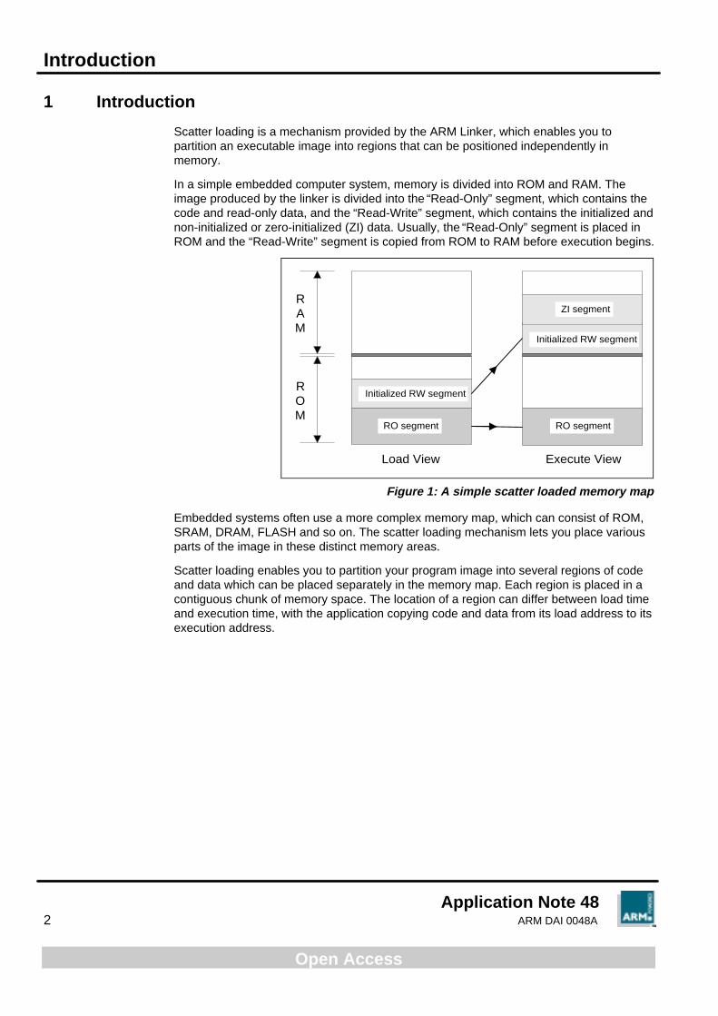
In a simple embedded computer system, memory is divided into ROM and RAM. Theimage produced by the linker is divided into the “Read-Only” segment, which contains thecode and read-only data, and the “Read-Write” segment, which contains the initialized andnon-initialized or zero-initialized (ZI) data. Usually, the “Read-Only” segment is placed inROM and the “Read-Write” segment is copied from ROM to RAM before execution begins.
ROM
RAM
Load View Execute View
Initialized RW segment
Initialized RW segment
ZI segment
RO segment RO segment
Figure 1: A simple scatter loaded memory map
Embedded systems often use a more complex memory map, which can consist of ROM,SRAM, DRAM, FLASH and so on. The scatter loading mechanism lets you place variousparts of the image in these distinct memory areas.
Scatter loading enables you to partition your program image into several regions of codeand data which can be placed separately in the memory map. Each region is placed in acontiguous chunk of memory space. The location of a region can differ between load timeand execution time, with the application copying code and data from its load address to itsexecution address.

Introduction
Application Note 48ARM DAI 0048A 3
Open Access
Load View Execute View
ROM
FLASH
SRAM
DRAM
ROM
FLASH
SRAM
DRAM
SRAM-resident code
SRAM-resident data
DRAM-resident dataand ZI-data description
ROM-residentcode and data
ROM-residentcode and data
DRAM-resident ZI data
DRAM-resident data
SRAM-resident code
SRAM-resident data
Figure 2: A more complicated scatter loaded memory map
The placement information is contained in a description file, the name of which is passedas a command line parameter to the linker.
Improvements Made to Scatter Loading in SDT 2.11
Application Note 484 ARM DAI 0048A
Open Access
2 Improvements Made to Scatter Loading in SDT 2.11
The original ARM scatter loading mechanism was introduced in SDT 2.0. The mechanismremained relatively unchanged in SDT 2.10. However, SDT 2.11 introduced majorimprovements to the scheme. This section details these improvements for users who arealready familiar with the previous scatter loading implementation.
The main improvements from the user’s point of view are:
• You no longer need special ROOT and ROOT-DATA regions. These werepreviously used to contain code and data not specified in any other area.However, they complicated the writing of description files for many users.
• You guide the assignment of areas to execution regions by writing patterns.Previously, a multiple match could not be diagnosed and the pattern presentedmost recently in the text would prevail. Now the most specific match is chosen ifthere is one, otherwise the description is diagnosed faulty.
• You have precise diagnostics: the linker identifies the line and column number offaults in a description file.
• You can now mark an area “first” or “last” in each execution region, though it muststill meet the requirement that, within each execution region, RO AREAs mustprecede the RW AREAs which must precede the ZI AREAs.
• New +n notation for the base address of an execution region allows you to placean execution region “n” bytes after the previous one. If it is used for the firstexecution region in the load region, the region is placed “n” bytes after the loadaddress. See 6.3 Example 3 on page 19.
• More linker-generated areas have been made assignable to an execution regionof your choice. This is particularly useful for placing the ARM/Thumb interworkingveneer area called IWV$$Code. See 6.3 Example 3 on page 19.
• The ARM ELF Image format is now fully supported.

Load Regions and Execution Regions
Application Note 48ARM DAI 0048A 5
Open Access
3 Load Regions and Execution Regions
A program image consists of regions which may occupy different locations at load timeand execution time.
This means that just before an image is executed, there are some regions which need tobe moved from the locations at which they were initially loaded in memory. For example,initialized read-write data may reside in ROM, but it must be copied into RAM when theprogram starts executing.
There are two mechanisms available to describe where image regions should be placed inmemory at execution time:
• Using -RO and -RW command line options, to specify the execution addresses of read-only and read-write regions. This is the simple method, used in systems which have asimple memory map of ROM and RAM, and where the image itself has one loadregion and two execution regions. See 4 Placing Execution Regions with -RO and -RW Options on page 6 for more information.
• Scatter loading, which is the preferred method for more complex memory maps andfor images which have more than two execution regions. See 5 Placing Regions withScatter Loading on page 10 for more information.
3.1 Definitions
Load region
The memory which is occupied by a program before it starts executing, but after it hasbeen loaded into memory, can be split into a set of disjoint load regions, each of which is acontiguous chunk of bytes.
Execution region
The memory used by a program while it is executing can also be split into a set of disjointexecution regions.
Note A load region contains one or more execution regions.
Note Each execution region belongs to only one load region.
Placing Execution Regions with -RO and -RW Options
Application Note 486 ARM DAI 0048A
Open Access
4 Placing Execution Regions with -RO and -RW Options
In a simple image, you can specify the execution addresses at which the “Read-Only”segment and the “Read-Write” segment will be placed in the memory map by using the-RO exec-address and -RW exec-address options of the linker, where:
-RO exec-address instructs the linker to place the “Read-Only” segment atexec address (often the address of the first location inROM)
-RW exec-address instructs the linker to place the “Read-Write” segment atexec address
Note -RO-base and -base options are equivalent to -RO. -RW-base and -RW-data optionsare equivalent to -RW.
At application load time, the RO region is loaded at its execution address and the RWregion is loaded immediately after the RO region.
The read-write (data) segment may contain code, as programs sometimes modifythemselves (or better, generate code and execute it). Similarly, the read-only (code) areamay contain read-only data (for example string literals, floating-point constants, ANSI Cconst data).
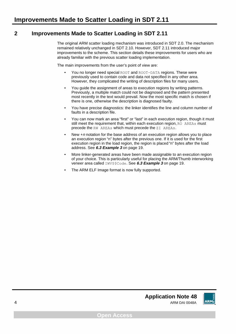
Using the addresses passed to it, the linker generates the symbols required to allow theregion to be copied from its load address to its execution addresses. These symbolsdescribe the execution address and the limit of each region. They are definedindependently of any input files and, along with all other external names containing $$, arereserved by ARM.
4.1.1 Linker pre-defined symbols
Load View
ROM
RAM
Execute ViewImage$$RO$$Base
Image$$RO$$Limit
Image$$ZI$$Base
Image$$RW$$Base
Image$$RW$$LimitImage$$ZI$$Limit
ZI segment
Initialized RW segment
Initialized RW segment
RO segment RO segment
Figure 3: Linker pre-defined symbols
Placing Execution Regions with -RO and -RW Options
Application Note 48ARM DAI 0048A 7
Open Access
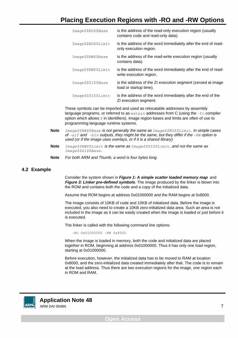
Image$$RO$$Base is the address of the read-only execution region (usuallycontains code and read-only data).
Image$$RO$$Limit is the address of the word immediately after the end of read-only execution region.
Image$$RW$$Base is the address of the read-write execution region (usuallycontains data).
Image$$RW$$Limit is the address of the word immediately after the end of read-write execution region.
Image$$ZI$$Base is the address of the ZI execution segment (zeroed at imageload or startup time).
Image$$ZI$$Limit is the address of the word immediately after the end of theZI execution segment.
These symbols can be imported and used as relocatable addresses by assemblylanguage programs, or referred to as extern addresses from C (using the -fc compileroption which allows $ in identifiers). Image region bases and limits are often of use toprogramming language runtime systems.
Note Image$$RW$$Base is not generally the same as Image$$RO$$Limit. In simple casesof -aif and -bin outputs, they might be the same, but they differ if the -RW option isused (or if the image uses overlays, or if it is a shared library).
Note Image$$RW$$Limit is the same as Image$$ZI$$Limit, and not the same asImage$$ZI$$Base.
Note For both ARM and Thumb, a word is four bytes long.
4.2 Example
Consider the system shown in Figure 1: A simple scatter loaded memory map andFigure 3: Linker pre-defined symbols. The image produced by the linker is blown intothe ROM and contains both the code and a copy of the initialized data.
Assume that ROM begins at address 0x01000000 and the RAM begins at 0x8000.
The image consists of 10KB of code and 10KB of initialized data. Before the image isexecuted, you also need to create a 10KB zero-initialized data area. Such an area is notincluded in the image as it can be easily created when the image is loaded or just before itis executed.
The linker is called with the following command line options:
-RO 0x01000000 -RW 0x8000
When the image is loaded in memory, both the code and initialized data are placedtogether in ROM, beginning at address 0x01000000. Thus it has only one load region,starting at 0x01000000.
Before execution, however, the initialized data has to be moved to RAM at location0x8000, and the zero-initialized data created immediately after that. The code is to remainat the load address. Thus there are two execution regions for the image, one region eachin ROM and RAM.
Placing Execution Regions with -RO and -RW Options
Application Note 488 ARM DAI 0048A
Open Access
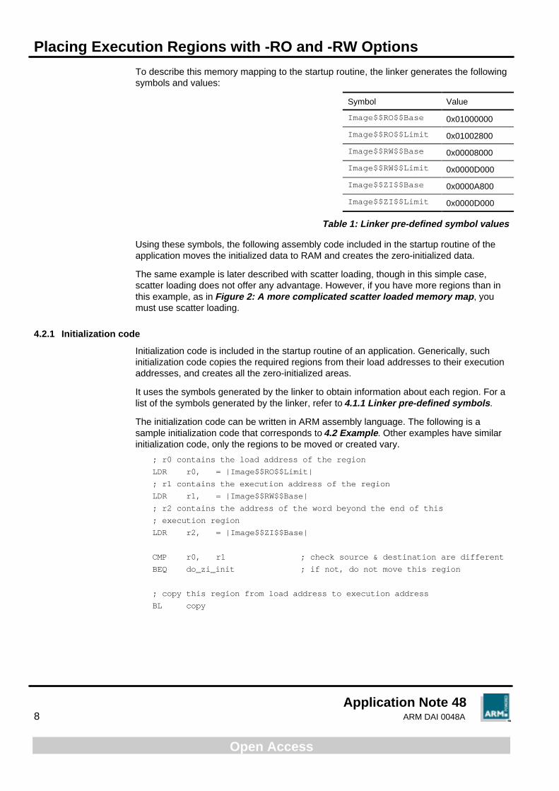
To describe this memory mapping to the startup routine, the linker generates the followingsymbols and values:
Symbol Value
Image$$RO$$Base 0x01000000
Image$$RO$$Limit 0x01002800
Image$$RW$$Base 0x00008000
Image$$RW$$Limit 0x0000D000
Image$$ZI$$Base 0x0000A800
Image$$ZI$$Limit 0x0000D000
Table 1: Linker pre-defined symbol values
Using these symbols, the following assembly code included in the startup routine of theapplication moves the initialized data to RAM and creates the zero-initialized data.
The same example is later described with scatter loading, though in this simple case,scatter loading does not offer any advantage. However, if you have more regions than inthis example, as in Figure 2: A more complicated scatter loaded memory map, youmust use scatter loading.
4.2.1 Initialization code
Initialization code is included in the startup routine of an application. Generically, suchinitialization code copies the required regions from their load addresses to their executionaddresses, and creates all the zero-initialized areas.
It uses the symbols generated by the linker to obtain information about each region. For alist of the symbols generated by the linker, refer to 4.1.1 Linker pre-defined symbols.
The initialization code can be written in ARM assembly language. The following is asample initialization code that corresponds to 4.2 Example. Other examples have similarinitialization code, only the regions to be moved or created vary.
; r0 contains the load address of the region
LDR r0, = |Image$$RO$$Limit|
; r1 contains the execution address of the region
LDR r1, = |Image$$RW$$Base|
; r2 contains the address of the word beyond the end of this
; execution region
LDR r2, = |Image$$ZI$$Base|
CMP r0, r1 ; check source & destination are different
BEQ do_zi_init ; if not, do not move this region
; copy this region from load address to execution address
BL copy
Placing Execution Regions with -RO and -RW Options
Application Note 48ARM DAI 0048A 9
Open Access
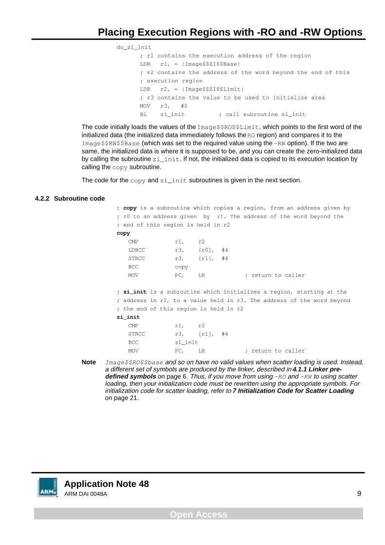
do_zi_init
; r1 contains the execution address of the region
LDR r1, = |Image$$ZI$$Base|
; r2 contains the address of the word beyond the end of this
; execution region
LDR r2, = |Image$$ZI$$Limit|
; r3 contains the value to be used to initialize area
MOV r3, #0
BL zi_init ; call subroutine zi_init
The code initially loads the values of the Image$$RO$$Limit, which points to the first word of theinitialized data (the initialized data immediately follows the RO region) and compares it to theImage$$RW$$Base (which was set to the required value using the -RW option). If the two aresame, the initialized data is where it is supposed to be, and you can create the zero-initialized databy calling the subroutine zi_init. If not, the initialized data is copied to its execution location bycalling the copy subroutine.
The code for the copy and zi_init subroutines is given in the next section.
4.2.2 Subroutine code; copy is a subroutine which copies a region, from an address given by
; r0 to an address given by r1. The address of the word beyond the
; end of this region is held in r2
copy
CMP r1, r2
LDRCC r3, [r0], #4
STRCC r3, [r1], #4
BCC copy
MOV PC, LR ; return to caller
; zi_init is a subroutine which initializes a region, starting at the
; address in r1, to a value held in r3. The address of the word beyond
; the end of this region is held in r2
zi_init
CMP r1, r2
STRCC r3, [r1], #4
BCC zi_init
MOV PC, LR ; return to caller
Note Image$$RO$$base and so on have no valid values when scatter loading is used. Instead,a different set of symbols are produced by the linker, described in 4.1.1 Linker pre-defined symbols on page 6. Thus, if you move from using -RO and -RW to using scatterloading, then your initialization code must be rewritten using the appropriate symbols. Forinitialization code for scatter loading, refer to 7 Initialization Code for Scatter Loadingon page 21.
Placing Regions with Scatter Loading
Application Note 4810 ARM DAI 0048A
Open Access
5 Placing Regions with Scatter Loading
Scatter loading is a mechanism to position load regions and execution regions in theirrespective memory maps. The region and position descriptions are given to the linker in adescription file.
5.1 Command line options
The ARM Linker generates a scatter loaded image when the option:
-scov description-file -scf
is given on its command line.
The -scov option accepts scatter load descriptions; -scf selects the respective outputformat.
Another way of specifying this is to use
-scatter description-file
Using scatter loading causes the linker to ignore the following options, which are irrelevantto scatter loading:
• -RO-base
• -RW-base
• -split
• -NoZeroPad (tells the linker not to pad the end of output binary with zeroes)
If a scatter loaded application requires overlays, the scatter load description file must beused to specify the overlays. The description of scatter loading with overlays can be foundin the Software Development Toolkit User Guide (ARM DUI 0040), 14.4 Overlays usingScatter Loading.
5.2 Image formats
Scatter load images can be output in three formats:
BIN
Generates one file for each load region, in the directory given as the output filename.These can then be blown into ROM, Flash and so on as appropriate. The output name istreated as a directory name. Each load region is placed in a separate file in that directory,with the same name as the load region. Load region names must therefore not containcharacters, or be of a length, unacceptable to the host file system.
AIF BIN
Generates a single extended AIF file suitable for loading into the debugger. A single outputfile containing one section per load region is produced (so-called fat AIF). The name of thefile is given by the -output option.
ELF
Generates a single executable ELF file suitable for loading into the debugger. A singleoutput file, containing one section per load region, is produced. The name of the file isgiven by the -output option.

Placing Regions with Scatter Loading
Application Note 48ARM DAI 0048A 11
Open Access
5.3 Linker pre-defined symbols
Using the region names given in the scatter loading description file, the linker generatesthe symbols required to allow each region to be copied from its load address to itsexecution address.
Neither the linker nor the C library provide the code required to copy an execution regionfrom its load address or create a zero-initialized region; you must do this, as theapplication code writer. Sample code is provided in 7 Initialization Code for ScatterLoading on page 21.
The linker generates symbols which allow your routine to initialize all the execution regionsthat have different load and execution addresses. These symbols give the length, loadaddress and execution address of each region.
Load View Execute ViewLoad$$ROM$$Base Image$$ROM$$Base
Image$$ROM$$LengthROM
FLASH
SRAM
DRAMImage$$DRAM$$ZI$$Base
Image$$DRAM$$ZI$$Length
Image$$SRAM$$Base
Image$$SRAM$$Length
Load$$RAM$$Base
DRAM-resident ZI data
DRAM-resident data
SRAM-resident data
SRAM-resident code
SRAM-resident code
SRAM-resident data
DRAM-resident dataand ZI-data description
ROM-resident codeand data
ROM-resident codeand data
Figure 4: Linker pre-defined symbols

Placing Regions with Scatter Loading
Application Note 4812 ARM DAI 0048A
Open Access
For RO and RW segments:
Load$$region_name$$Base is the load address of the region
Image$$region_name$$Base is the execution address of the region
Image$$region_name$$Length is the execution region length in bytes(multiple of 4)
For zero-initialized segments:
Image$$region_name$$ZI$$Base is the execution address of the region
Image$$region_name$$ZI$$Length is the execution region length in bytes(multiple of 4)
These symbols can be imported and used by assembly language programs, or referred toas extern addresses from C (using the -fc compiler option which allows $ in identifiers).
Note These symbols are generated for every region named in the scatter load description.
A scatter load image is not padded with zeros, and requires the ZI data areas to becreated dynamically. This is similar to the case with a normal -bin file when the-nozeropad option is used. There is therefore no need for a load address symbol for ZIdata.
The linker sorts AREAs within execution regions according to their attributes. For example,all initialized data areas are grouped together. Therefore, you can assume that allinitialized data that needs copying is contiguous.
5.4 Area ordering
The linker orders AREAs within each execution region by attributes. The ordering is:
• read-only code
• read-only based data
• read-only data
• read-write code
• based data
• other initialized data
• zero-initialized data
The pseudo-attributes FIRST and LAST can be used in the description file to mark the firstand last AREAs in an execution region if the placement order is important (for example, ifthe ENTRY must be first and a checksum last).
However, FIRST and LAST must not violate the basic attribute sorting order. That impliesthat in a region containing any read-only AREAs, the FIRST AREA must be a read-onlyarea. Similarly, if the region contains any ZI data, the LAST AREA must be a ZI area.

Placing Regions with Scatter Loading
Application Note 48ARM DAI 0048A 13
Open Access
5.5 Scatter loading and long distance branching
The ARM instruction set has branch instructions that allow a branch forwards orbackwards up to 32Mb. A subroutine call is a variant of the standard branch; as well asallowing a branch forwards or backwards up to 32Mb, the BL (Branch with Link) instructionalso preserves the return address in register 14 (Link Register, LR).
The Thumb instruction set has much shorter branch ranges, from 256 bytes in the case ofconditional branches to 2048 bytes for unconditional branches. The BL instruction has arange of 4Mb.
The linker has to ensure that no branch or subroutine call violates these range restrictions.If you place your execution regions in such a way as to require inter-region branchesbeyond the range, the linker generates an error stating Relocated value too bigfor instruction sequence.
There are two ways to work around this restriction:
• Using function pointers in code, removing the dependence on branch ranges.
• Calling the out-of-range routines via assembler veneers.
For example, if the application currently has a function:
int func(int a, int b);
which is invoked as:
func( a, b);
you can change this using function pointers into:
typedef int FuncType( int, int);
FuncType *fn = func;
and invoke the function as:
fn( a, b);
If you use assembly veneers, you can write it as
asm_func(a,b);
where asm_func is an assembler routine.
As ARM and Thumb assembly languages differ, the code for the assembler veneers isslightly different.
The following is the assembly veneer for ARM:
AREA arm_longbranch_veneers, CODE, READONLY
EXPORT asm_func
IMPORT func
asm_func
LDR pc, addr_func
addr_func
DCD func
END
Placing Regions with Scatter Loading
Application Note 4814 ARM DAI 0048A
Open Access
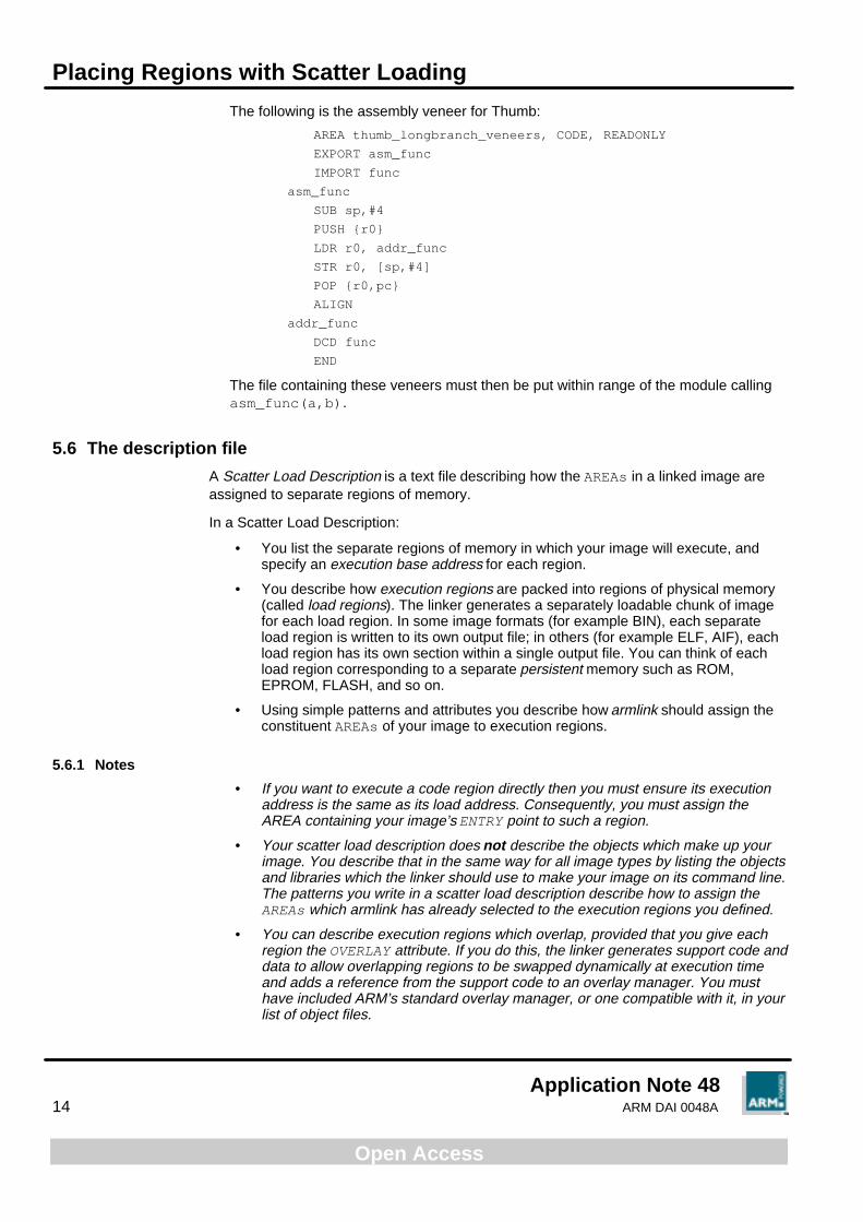
The following is the assembly veneer for Thumb:
AREA thumb_longbranch_veneers, CODE, READONLY
EXPORT asm_func
IMPORT func
asm_func
SUB sp,#4
PUSH {r0}
LDR r0, addr_func
STR r0, [sp,#4]
POP {r0,pc}
ALIGN
addr_func
DCD func
END
The file containing these veneers must then be put within range of the module callingasm_func(a,b).
5.6 The description file
A Scatter Load Description is a text file describing how the AREAs in a linked image areassigned to separate regions of memory.
In a Scatter Load Description:
• You list the separate regions of memory in which your image will execute, andspecify an execution base address for each region.
• You describe how execution regions are packed into regions of physical memory(called load regions). The linker generates a separately loadable chunk of imagefor each load region. In some image formats (for example BIN), each separateload region is written to its own output file; in others (for example ELF, AIF), eachload region has its own section within a single output file. You can think of eachload region corresponding to a separate persistent memory such as ROM,EPROM, FLASH, and so on.
• Using simple patterns and attributes you describe how armlink should assign theconstituent AREAs of your image to execution regions.
5.6.1 Notes
• If you want to execute a code region directly then you must ensure its executionaddress is the same as its load address. Consequently, you must assign theAREA containing your image’s ENTRY point to such a region.
• Your scatter load description does not describe the objects which make up yourimage. You describe that in the same way for all image types by listing the objectsand libraries which the linker should use to make your image on its command line.The patterns you write in a scatter load description describe how to assign theAREAs which armlink has already selected to the execution regions you defined.
• You can describe execution regions which overlap, provided that you give eachregion the OVERLAY attribute. If you do this, the linker generates support code anddata to allow overlapping regions to be swapped dynamically at execution timeand adds a reference from the support code to an overlay manager. You musthave included ARM’s standard overlay manager, or one compatible with it, in yourlist of object files.

Placing Regions with Scatter Loading
Application Note 48ARM DAI 0048A 15
Open Access
• ARM-Thumb interworking veneers are built in an AREA called IWV$$Code. Youcan assign this AREA to an execution region just like any other area using theAREA selector:
*(IWV$$Code)
Although there is no associated module, * still matches. Because there is onlyone IWV$$Code AREA, this selection is unambiguous.
A detailed description of the file format is given at the end of this Application Note.
Scatter Loading Examples
Application Note 4816 ARM DAI 0048A
Open Access
6 Scatter Loading Examples
The following examples describe some scatter loading scenarios of increasing complexity.Each example includes a memory map, a description file and a table of linker-generatedsymbols. A generic initialization routine is also explained which can be used with all thesescatter loading examples.
6.1 Example 1
This is the same example that is explained in 4.2 Example on page 7 using the -RO and-RW options.
Memory map
The memory map has just one block of ROM (beginning at address 0x01000000), and oneblock of RAM (beginning at address 0x00008000). The image produced by the linker isblown into the ROM and contains both the code and a copy of the initialized data.
Image properties
The image is contained in a single object file called object1.o.
The image consists of 10KB of code and 10KB of initialized data. Before the image isexecuted, you must also create a 10KB zero-initialized data area.
When the image is loaded in memory, both the code and initialized data are placedtogether in ROM, beginning at address 0x01000000. Thus the image has only one loadregion, starting at 0x01000000.
Before execution, however, the initialized data has to be moved to RAM at location0x8000, and the zero-initialized data created immediately afterwards. The code is toremain at the load address. There are therefore two execution regions for the image, oneregion each in ROM and RAM.
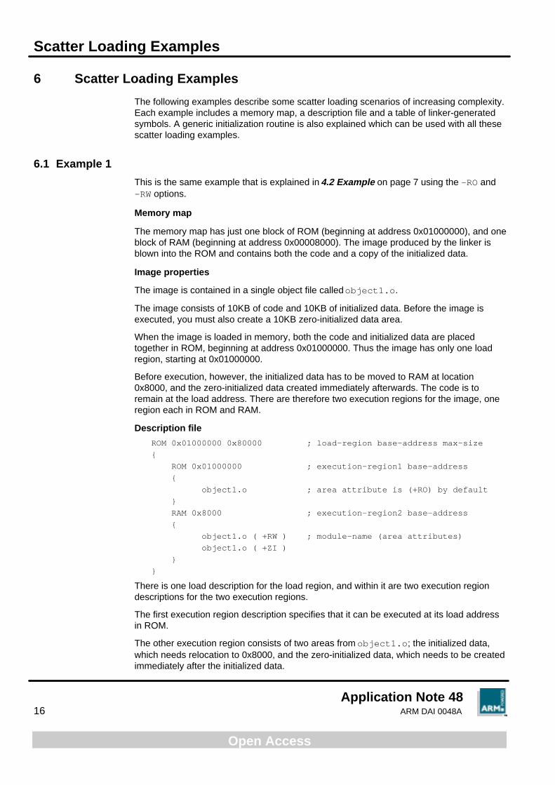
Description file
ROM 0x01000000 0x80000 ; load-region base-address max-size
{
ROM 0x01000000 ; execution-region1 base-address
{
object1.o ; area attribute is (+RO) by default
}
RAM 0x8000 ; execution-region2 base-address
{
object1.o ( +RW ) ; module-name (area attributes)
object1.o ( +ZI )
}
}
There is one load description for the load region, and within it are two execution regiondescriptions for the two execution regions.
The first execution region description specifies that it can be executed at its load addressin ROM.
The other execution region consists of two areas from object1.o; the initialized data,which needs relocation to 0x8000, and the zero-initialized data, which needs to be createdimmediately after the initialized data.

Scatter Loading Examples
Application Note 48ARM DAI 0048A 17
Open Access
Symbols
To describe this memory mapping to the startup routine, the linker generates the followingsymbols and values:
Symbol Value
Load$$ROM$$Base 0x01000000
Image$$ROM$$Base 0x01000000
Image$$ROM$$Length 0x2800
Load$$RAM$$Base 0x01002800
Image$$RAM$$Base 0x8000
Image$$RAM$$Length 0x2800
Image$$RAM$$ZI$Base 0xA800
Image$$RAM$$ZI$$Length 0x2800
Table 2: Example 1symbol values
6.2 Example 2
Memory map
The memory map is shown in the following table:
Name Base Size
ROM 0x0000 0x8000
SRAM 0x8000 0x8000
EEPROM 0x10000 0x8000
DRAM 0x18000 0x8000
Table 3: Example 2memory map
Image properties
The image is contained in two object files: object1.o and object2.o.
There are three areas in each of the object files (RO, RW, and ZI).
When the image is loaded in memory, assume that the RO and RW areas fromobject1.o are placed in ROM starting at 0x0000, and the RO and RW areas fromobject2.o are placed in ROM starting at 0x4000. The image therefore has two loadregions.
Before execution, the DRAM should contain the RW area from object1.o and the ZIarea from object2.o. The SRAM should contain the RW area from object2.o and theZI area from object1.o.

Scatter Loading Examples
Application Note 4818 ARM DAI 0048A
Open Access
The required positions of the various areas are:
From object1.o The RO area remains where it is loaded.
The RW area needs to be placed in DRAM at 0x18000.
The ZI area needs to be created in SRAM.
From object2.o The RO area remains where it is loaded.
The RW area needs to be placed in SRAM at 0x8000.
The ZI area needs to be created in DRAM.
For simplicity, assume that each area is of the same size: 1024 bytes (0x400)
Description file
ROM_1 0x0000 ; load-region-name base-address
{
ROM 0x0000 ; execution-region1-name base-address
{
object1.o (+RO)
}
DRAM 0x18000 ; execution-region2-name base-address
{
object1.o (+RW)
object2.o (+ZI)
}
}
ROM_2 0x4000
{
ROM_2 0x4000 ; execution-region1-name base-address
{
object2.o (+RO)
}
SRAM 0x8000 ; execution-region2-name base-address
{
object1.o (+ZI)
object2.o (+RW)
}
}
There are therefore two load regions and four execution regions.

Scatter Loading Examples
Application Note 48ARM DAI 0048A 19
Open Access
Symbols
To describe this memory mapping to the startup routine, the linker generates the followingsymbols and values:
Symbol Value
Load$$ROM_1$$Base 0x0000
Image$$ROM_1$$Base 0x0000
Image$$ROM_1$$Length 0x400
Load$$DRAM$$Base 0x0400
Image$$DRAM$$Base 0x18000
Image$$DRAM$$Length 0x400
Image$$DRAM$$ZI$$Base 0x18400
Image$$DRAM$$ZI$$Length 0x400
Load$$ROM_2$$Base 0x4000
Image$$ROM_2$$Base 0x4000
Image$$ROM_2$$Length 0x400
Load$$SRAM$$Base 0x4400
Image$$SRAM$$Base 0x8000
Image$$SRAM$$Length 0x400
Image$$SRAM$$ZI$$Base 0x8400
Image$$SRAM$$ZI$$Length 0x400
Table 4: Example 2symbol values
6.3 Example 3
Memory map
The memory map is shown in the following table:
Name Base Size
ROM 0x0000 0x8000
RAM 0x8000 0x10000
Table 5: Example 3memory map
Image properties
The image is contained in one object file called object1.o.
There are three areas in the object files (RO, RW, and ZI).
There is also an Interworking veneer area called IWV$$Code within object1.o.
When the image is loaded in memory, it is loaded in ROM at 0x0000, and has only oneload region.
Scatter Loading Examples
Application Note 4820 ARM DAI 0048A
Open Access
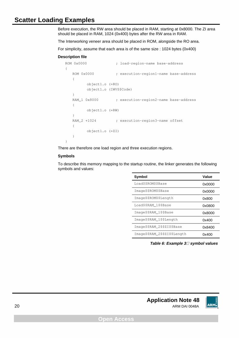
Before execution, the RW area should be placed in RAM, starting at 0x8000. The ZI areashould be placed in RAM, 1024 (0x400) bytes after the RW area in RAM.
The Interworking veneer area should be placed in ROM, alongside the RO area.
For simplicity, assume that each area is of the same size : 1024 bytes (0x400)
Description file
ROM 0x0000 ; load-region-name base-address
{
ROM 0x0000 ; execution-region1-name base-address
{
object1.o (+RO)
object1.o (IWV$$Code)
}
RAM_1 0x8000 ; execution-region2-name base-address
{
object1.o (+RW)
}
RAM_2 +1024 ; execution-region3-name offset
{
object1.o (+ZI)
}
}
There are therefore one load region and three execution regions.
Symbols
To describe this memory mapping to the startup routine, the linker generates the followingsymbols and values:
Symbol Value
Load$$ROM$$Base 0x0000
Image$$ROM$$Base 0x0000
Image$$ROM$$Length 0x800
Load$$RAM_1$$Base 0x0800
Image$$RAM_1$$Base 0x8000
Image$$RAM_1$$Length 0x400
Image$$RAM_2$$ZI$$Base 0x8400
Image$$RAM_2$$ZI$$Length 0x400
Table 6: Example 3symbol values

Initialization Code for Scatter Loading
Application Note 48ARM DAI 0048A 21
Open Access
7 Initialization Code for Scatter Loading
You should place your scatter loading initialization code in the startup routine of anapplication. Your initialization code should copy the required regions from their loadaddresses to their execution addresses, and create all the zero-initialized areas.
The code uses the symbols generated by the linker to obtain information about eachregion. For a list of the symbols generated by the linker, refer to 5.3 Linker pre-definedsymbols on page 11.
The initialization code can be written in ARM assembly language. The following is asample initialization code that corresponds to 6.1 Example 1 on page 16. Other exampleshave similar initialization code, only the regions to be moved or created vary.
; r0 contains the load address of the region RAM
LDR r0, = |Load$$RAM$$Base|
; r1 contains the execution address of the region RAM
LDR r1, = |Image$$RAM$$Base|
CMP r0, r1 ; check source & destination are different
BEQ do_zi_init ; if not, do not copy this region
; copy this region from load address to execution address
; r2 contains the address of the word beyond the end of this
; execution region
MOV r2, r1
LDR r4, = |Image$$RAM$$length|
ADD r2, r2, r4
BL copy
do_zi_init
; r1 contains the execution address of the region
LDR r1, = |Image$$RAM$$ZI$$Base|
; r2 contains the address of the word beyond the end of this
; execution region
MOV r2, r1
LDR r4, = |Image$$RAM$$ZI$$length|
ADD r2, r2, r4
; r3 contains the value to be used to initialise area
MOV r3, #0
BL zi_init ; call subroutine zi_init
The code initially loads the values of the Load$$RAM$$Base, which is the load address ofthe region called RAM, and compares it to the Image$$RAM$$Base, which is theexecution address. If the two are same, then the region is where it is supposed to be, andyou can create the zero-initialized data, by calling the subroutine zi_init. If not, theregion RAM is copied to its execution location by calling the copy subroutine.
The code for the copy and zi_init subroutines is given in 4.2.2 Subroutine code onpage 9.
The Description File Format
Application Note 4822 ARM DAI 0048A
Open Access
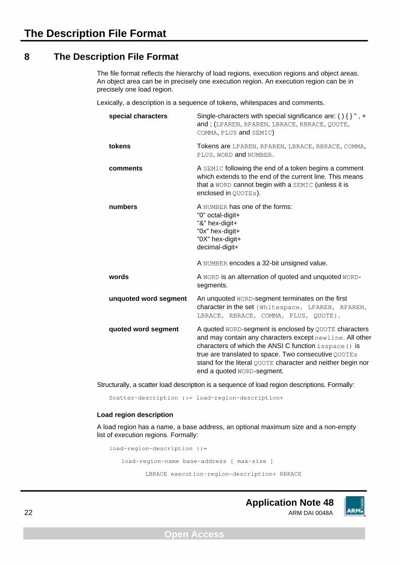
8 The Description File Format
The file format reflects the hierarchy of load regions, execution regions and object areas.An object area can be in precisely one execution region. An execution region can be inprecisely one load region.
Lexically, a description is a sequence of tokens, whitespaces and comments.
special characters Single-characters with special significance are: ( ) { } " , +and ; (LPAREN, RPAREN, LBRACE, RBRACE, QUOTE,COMMA, PLUS and SEMIC)
tokens Tokens are LPAREN, RPAREN, LBRACE, RBRACE, COMMA,PLUS, WORD and NUMBER.
comments A SEMIC following the end of a token begins a commentwhich extends to the end of the current line. This meansthat a WORD cannot begin with a SEMIC (unless it isenclosed in QUOTEs).
numbers A NUMBER has one of the forms:"0" octal-digit+"&" hex-digit+"0x" hex-digit+"0X" hex-digit+decimal-digit+
A NUMBER encodes a 32-bit unsigned value.
words A WORD is an alternation of quoted and unquoted WORD-segments.
unquoted word segment An unquoted WORD-segment terminates on the firstcharacter in the set {Whitespace, LPAREN, RPAREN,LBRACE, RBRACE, COMMA, PLUS, QUOTE} .
quoted word segment A quoted WORD-segment is enclosed by QUOTE charactersand may contain any characters except newline. All othercharacters of which the ANSI C function isspace() istrue are translated to space. Two consecutive QUOTEsstand for the literal QUOTE character and neither begin norend a quoted WORD-segment.
Structurally, a scatter load description is a sequence of load region descriptions. Formally:
Scatter-description ::= load-region-description+
Load region description
A load region has a name, a base address, an optional maximum size and a non-emptylist of execution regions. Formally:
load-region-description ::=
load-region-name base-address [ max-size ]
LBRACE execution-region-description+ RBRACE

The Description File Format
Application Note 48ARM DAI 0048A 23
Open Access
The linker allows an empty description.
Only the first 31 characters of the load-region-name are significant. In multi-file outputformats (for example -BIN -SCATTER) load-region-name is used to name the filecontaining initializing data for this load region. On hosts which have shorter limits ondirectory entries, fewer characters are used.
The first 31 characters of load-region-name are also used to manufacture base andlimit symbols for the region.
base-address is the address at which the contents of the region are loaded. It must be aword-aligned NUMBER, so &1234ABDC, 0x1e4,4000 and 0 are acceptable, but 1234CD isnot.
max-size is an optional NUMBER: if specified, the description is faulted if the region hasmore than max-size bytes allocated to it.
Execution region description
An execution region is described by a name, a base address and an optional OVERLAYattribute. Formally:
execution-region-description ::=
exec-region-name base-designator [ “OVERLAY” ]
LBRACE object-AREA-description* RBRACE
base-designator ::= base-address | “+” offset
The “+” offset form of base-designator describes a base-address offset bytesbeyond the end of the preceding execution region. The length of a region is always amultiple of four bytes, so offset must be a multiple of four bytes too. If there is nopreceding execution region (that is, if this is the first in the load region) then “+” offsetmeans offset bytes after the base of the containing load region.
base-address is the address at which objects in the region should be linked. It must bea word-aligned NUMBER.
Armlink faults overlapping execution regions unless they have the “OVERLAY” attribute.For overlay regions that overlap, armlink builds clash maps and generates a reference tothe overlay manager (which must already have been included in the image). Overlaysegments are given names derived from the exec-region-name.
A root region is a non-OVERLAY execution region with its load address equal to itsexecution address. Only a root region may contain an entry point.
Object area descriptions
An object-AREA-description is a pattern that identifies AREAs by:
• module name (object file name, library member name or library file name) and;
• AREA name or AREA attributes such as READ-ONLY, CODE, and so on. Formally:
object-AREA-description ::=
module-selector-pattern [ LPAREN area-selectors RPAREN ]
An omitted LPAREN area-selectors RPAREN defaults to (+RO) (see below).
The Description File Format
Application Note 4824 ARM DAI 0048A
Open Access
area-selectors is a comma-separated list of expressions. Each expression is a patternagainst which the AREA name, or the name of an attribute you want the selected AREA tohave, is matched. In the latter case the name must be preceded by a plus (+). You mayomit any comma immediately followed by a PLUS. Formally:
area-selectors ::=
(PLUS area-attrs | area-pattern )([ COMMA ] PLUS area-attrs |COMMA area-pattern)*
Additionally, the first occurrence of FIRST or LAST as an area-attrs terminates the list.
Only AREAs that match both the module-selector and at least one area-selector areincluded in the execution region.
If an AREA matches more than one execution region, the matches are disambiguated asdescribed below. If a unique match cannot be found, armlink faults the scatter description.
Note that the assignment of AREAs to regions is completely independent of the order inwhich patterns are written in the scatter load description.
Module-selector patterns and area patterns
A module-selector-pattern and an area-pattern are patterns constructed fromliteral text, and the wildcard characters * (matches 0 or more characters) and ? (matchesany single character). For example:
*armlib.* ; matches AREAs from any armlib.*
An AREA matches a module-selector-pattern if:
• the name of the object file containing the AREA or name of the library member(with no leading pathname) matches the module-selector-pattern
• the full name of the library from which the AREA was extracted matches themodule-selector-pattern
Matching is case-insensitive, even on hosts with case-sensitive file naming.
Area selector
An area-selector is:
• a pattern matched case-insensitively against the AREA’s name
• an attribute selector matched against the area’s attributes
Note ARM-Thumb interworking veneers are built in an AREA called IWV$$Code. You canassign this AREA to an execution region just like any other area using the AREA selector:
*(IWV$$Code)
Although there is no associated module, * still matches; because there is only oneIWV$$Code AREA, this selection is unambiguous.

The Description File Format
Application Note 48ARM DAI 0048A 25
Open Access
An attribute selector follows a plus (+) character. The following selectors are recognized(case-insensitively):
RO-CODERO-BASED-DATA
RO-DATA (includes RO-BASED-DATA)
RO (includes RO-CODE and RO-DATA)RW-CODERW-BASED-DATA
RW-STUB-DATA (shared library stub data)
RW-DATA (includes RW-BASED-DATA and RW-STUB-DATA)
RW (includes RW-CODE and RW-DATA)ZI
ENTRY (the AREA containing the ENTRY point)
The following synonyms are recognized:
CODE (= RO-CODE)CONST (= RO-DATA)TEXT (= RO)DATA (= RW)BSS (= ZI)
The following pseudo attributes are recognized:
FIRSTLAST
The pseudo-attributes FIRST and LAST can be used to mark the first and last AREAs inan execution region if the placement order is important (for example, if the ENTRY must befirst and a checksum last).
Note that RO-NOTBASED-DATA cannot be specified directly. Rather, RO-BASED-DATAmust be selected in one region and (less specifically) RO-DATA in another.
Disambiguating multiple matches
Every AREA is selected by a module-selector and an area-selector. Suppose AREA Amatches m1,s1 for execution region R1 and m2,s2 for execution region R2:
1 Assign A to R1 if and only if (iff) m1,s1 < (more specific than) m2,s2.
2 Assign A to R2 iff m2,s2 < m1,s1.
3 Diagnose the scatter description as faulty if neither m1,s1 < m2,s2 nor m2,s2 <m1,s1.
4 Define m1,s1 < m2,s2 iff:
a) s1 is a literal AREA name (containing no pattern characters) and s2 matchesAREA attributes other than +ENTRY; or
b) (m1 < m2) || !(m2 < m1) && (s1 < s2)
5 Define m1 < m2 iff:
(text(m1) matches pattern(m2)) && !(text(m2) matchespattern(m1))
The Description File Format
Application Note 4826 ARM DAI 0048A
Open Access
6 If s1 and s2 are both patterns matching AREA names, the same definition of s1 <s2 holds as for m1 < m2.
Otherwise, if one of s1, s2 matches the AREA name and the other matches theAREAs attributes then neither s1 < s2 nor s2 < s1.
7 If both s1 and s2 match AREA attributes then define s1 < s2 by: ENTRY < RO-CODE < RO ENTRY < RO-BASED-DATA < RO-DATA < RO ENTRY < RW-CODE < RW ENTRY < RW-BASED-DATA < RW-DATA < RW ENTRY < RW-STUB-DATA < RW-DATA < RW
No other members of the s1 < s2 relation between AREA attributes exist.
Consequences of this matching strategy include:
• All warning-free SDT2.1 descriptions remain valid.
• Some descriptions warned of in SDT2.1 succeed without warning; some arefaulted.
• Descriptions become independent of the order in which they are written (also trueof SDT2.1 warning-free descriptions).
• Usually, the more specific description of an object is the more specific descriptionof the AREAs it contains: AREA selectors are not examined unless object selectionis inconclusive or one selector fully names an AREA and the other selects byattribute. In this case, the explicit AREA name is more specific than any attributeother than ENTRY (which selects exactly one AREA from one object), even if theobject selector associated with the AREA name is less specific than thatassociated with the attribute.
Default root region specification (obsolete)
The use of ROOT and ROOT-DATA declarations is now discouraged.
You should not use them in new scatter loading descriptions. Armlink uses the defaultROOT to contain debug data and other impedimenta, but this is best kept separate fromyour image. They exist in SDT 2.11 only for backward compatibility, and future versions ofArmlink may stop recognizing them in the description file.
You can specify a default ROOT region to contain AREAs you do not assign to any otherexecution region. You can also specify a default ROOT-DATA region. If you do, theunassigned read-only AREAs are placed in the default ROOT and unassigned read-writeAREAs are placed in the default ROOT-DATA. You cannot specify a default ROOT-DATAregion unless you specify a default ROOT.
You describe the default ROOT regions as follows:
ROOT root_load-address [ root_max_size ]
ROOT-DATA root_data_load_address
The Description File Format
Application Note 48ARM DAI 0048A 27
Open Access
This is similar to:
ROOT root_load_address
{
; the ROOT load region
ROOT root_load_address { *(*) }
}
or
ROOT root_load_address
{
; the ROOT load region
ROOT root_load_address { *(+RO) }
ROOT-DATA root_data_load_address { *(+RW,+ZI) }
}
as described in 3 Load Regions and Execution Regions on page 5.
The region names ROOT and ROOT-DATA are reserved for armlink. If you do not specify adefault ROOT, armlink faults any areas not placed specifically by your scatter description.