SBX-3000-16T User Manual - ネットワーク : 富士通 STP Global STP Port Settings .....38 STP...
71
Fujutsu SH-E514TR1 10 Gigabit Ethernet SmartPro Switch User Manual
Transcript of SBX-3000-16T User Manual - ネットワーク : 富士通 STP Global STP Port Settings .....38 STP...

Fujutsu SH-E514TR1 10 Gigabit Ethernet SmartPro Switch
User Manual

FCC Warning
This equipment has been tested and found to comply with the limits for a Class A digital device, pursuant to Part 15 of the FCC Rules. These limits are designed to provide reasonable protection against harmful interference when the equipment is operated in a commercial environment. This equipment generates, uses, and can radiate radio frequency energy and, if not installed and used in accordance with this manual, may cause harmful interference to radio communications. Operation of this equipment in a residential area is likely to cause harmful interference in which case the user will be required to correct the interference at his expense.
Warning: Changes or modifications to this unit not expressly approved by the party responsible for compliance could void the user authority to operate the equipment.
CE Mark Warning
This is a Class A product. In a domestic environment, this product may cause radio interference in which case the user may be required to take adequate measures.
Warnung!
Dies ist ein Produkt der Klasse A. Im Wohnbereich kann dieses Produkt Funkstoerungen verursachen. In diesem Fall kann vom Benutzer verlangt werden, angemessene Massnahmen zu ergreifen.
Precaución!
Este es un producto de Clase A. En un entorno doméstico, puede causar interferencias de radio, en cuyo case, puede requerirse al usuario para que adopte las medidas adecuadas.
Attention!
Ceci est un produit de classe A. Dans un environnement domestique, ce produit pourrait causer des interférences radio, auquel cas l`utilisateur devrait prendre les mesures adéquates.
Attenzione!
Il presente prodotto appartiene alla classe A. Se utilizzato in ambiente domestico il prodotto può causare interferenze radio, nel cui caso è possibile che l`utente debba assumere provvedimenti adeguati.
VCCI Warning
この装置は、クラス A 情報技術装置です。この装置を家庭環境で使用すると電波妨害を引き起こすことがあります。
この場合には使用者が適切な対策を講ずるよう要求されることがあります。 VCCI-A
BSMI Notice
此為甲類資訊技術設備,於居住環境中使用時,可能會造成射頻擾動,在此種情況下,使用者會被要求採取某些適當的
對策。
Safety Compliance
Warning: Class 1 Laser Product.
EN: When using a fiber optic media expansion module, never look at the transmit laser while it is powered on. Also, never look directly at the fiber TX port and fiber cable ends when they are powered on.
FR: Ne regardez jamais le laser tant qu’il est sous tension. Ne regardez jamais directement le port TX (Tramsmission) à fibres optiques et les embouts de câbles à fibres optiques tant qu’ils sont sous tension.
SFP (Mini-GBIC), XENPAK, and XFP Regulatory Compliance
Networks pluggable optical modules meet the following regulatory requirements:
Class 1.
IEC/EN60825-1:2007 2nd Edition or later, European Standard
FCC 21 CFR Chapter 1, Subchapter J in accordance with FDA and CDRH requirements.
Application of CE Mark in accordance with 2004/108/EEC EMC Directive and the 2006/95/EC Low Voltage Directives.
UL and/or CSA registered component for North America.
47 CFR Part 15, Class A when installed into products.
SH-E514TR1 10 Gigabit Ethernet SmartPro Switch User Manual
i
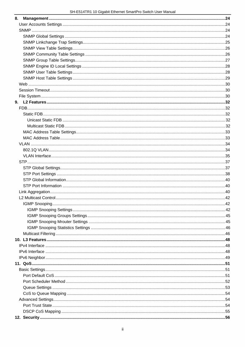
Table of Contents
1. Intended Readers ..................................................................................................................................................... 1
Terms/Usage ................................................................................................................................................................. 1
Safety Instructions ......................................................................................................................................................... 1
General Precautions for Rack-Mountable Products ...................................................................................................... 2
Protecting Against Electrostatic Discharge ................................................................................................................... 3
2. Product Introduction ............................................................................................................................................... 4
3. Getting Started ......................................................................................................................................................... 5
Recommended Web Browsers ...................................................................................................................................... 5
Connecting to the Switch ............................................................................................................................................... 5
Login Web-based Management .................................................................................................................................... 5
4. Web-based Management ......................................................................................................................................... 7
5. Tool Bar ..................................................................................................................................................................... 8
Save ............................................................................................................................................................................... 8
Save Configuration .................................................................................................................................................... 8
Tools .............................................................................................................................................................................. 8
Firmware Upgrade and Backup ................................................................................................................................. 8
Firmware Upgrade from HTTP ............................................................................................................................... 9
Firmware Upgrade from TFTP ............................................................................................................................... 9
Firmware Backup to HTTP ..................................................................................................................................... 9
Firmware Backup to TFTP ................................................................................................................................... 10
Configuration Restore and Backup .......................................................................................................................... 10
Configuration Restore from HTTP ........................................................................................................................ 10
Configuration Restore from TFTP ........................................................................................................................ 11
Configuration Backup to HTTP ............................................................................................................................ 11
Configuration Backup to TFTP ............................................................................................................................. 11
Log Backup .............................................................................................................................................................. 12
Log Backup to HTTP ............................................................................................................................................ 12
Log Backup to TFTP ............................................................................................................................................ 12
Ping .......................................................................................................................................................................... 13
Reset ........................................................................................................................................................................ 13
Reboot System ........................................................................................................................................................ 14
6. Device Information ................................................................................................................................................. 15
7. System .................................................................................................................................................................... 16
System Information Settings ........................................................................................................................................ 16
Peripheral Settings ...................................................................................................................................................... 16
Port Configuration ........................................................................................................................................................ 16
Port Settings ............................................................................................................................................................ 16
Port Status ............................................................................................................................................................... 17
Error Disable Settings .............................................................................................................................................. 18
Jumbo Frame ........................................................................................................................................................... 18
System Log .................................................................................................................................................................. 19
System Log Settings ................................................................................................................................................ 19
System Log Discriminator Settings .......................................................................................................................... 20
System Log Server Settings .................................................................................................................................... 20
System Log .............................................................................................................................................................. 21
System Attack Log ................................................................................................................................................... 21
Time and SNTP ........................................................................................................................................................... 21
Clock Settings .......................................................................................................................................................... 22
Time Zone Settings .................................................................................................................................................. 22
SNTP Settings ......................................................................................................................................................... 23
SH-E514TR1 10 Gigabit Ethernet SmartPro Switch User Manual
ii
8. Management ........................................................................................................................................................... 24
User Accounts Settings ............................................................................................................................................... 24
SNMP .......................................................................................................................................................................... 24
SNMP Global Settings ............................................................................................................................................. 24
SNMP Linkchange Trap Settings ............................................................................................................................. 25
SNMP View Table Settings ...................................................................................................................................... 26
SNMP Community Table Settings ........................................................................................................................... 26
SNMP Group Table Settings.................................................................................................................................... 27
SNMP Engine ID Local Settings .............................................................................................................................. 28
SNMP User Table Settings ...................................................................................................................................... 28
SNMP Host Table Settings ...................................................................................................................................... 29
Web ............................................................................................................................................................................. 30
Session Timeout .......................................................................................................................................................... 30
File System .................................................................................................................................................................. 30
9. L2 Features ............................................................................................................................................................. 32
FDB .............................................................................................................................................................................. 32
Static FDB ................................................................................................................................................................ 32
Unicast Static FDB ............................................................................................................................................... 32
Multicast Static FDB ............................................................................................................................................. 32
MAC Address Table Settings ................................................................................................................................... 33
MAC Address Table ................................................................................................................................................. 33
VLAN ........................................................................................................................................................................... 34
802.1Q VLAN ........................................................................................................................................................... 34
VLAN Interface ......................................................................................................................................................... 35
STP .............................................................................................................................................................................. 37
STP Global Settings ................................................................................................................................................. 37
STP Port Settings .................................................................................................................................................... 38
STP Global Information ............................................................................................................................................ 40
STP Port Information ............................................................................................................................................... 40
Link Aggregation .......................................................................................................................................................... 40
L2 Multicast Control ..................................................................................................................................................... 42
IGMP Snooping ........................................................................................................................................................ 42
IGMP Snooping Settings ...................................................................................................................................... 42
IGMP Snooping Groups Settings ......................................................................................................................... 45
IGMP Snooping Mrouter Settings ........................................................................................................................ 45
IGMP Snooping Statistics Settings ...................................................................................................................... 46
Multicast Filtering ..................................................................................................................................................... 46
10. L3 Features ............................................................................................................................................................. 48
IPv4 Interface .............................................................................................................................................................. 48
IPv6 Interface .............................................................................................................................................................. 48
IPv6 Neighbor .............................................................................................................................................................. 49
11. QoS .......................................................................................................................................................................... 51
Basic Settings .............................................................................................................................................................. 51
Port Default CoS ...................................................................................................................................................... 51
Port Scheduler Method ............................................................................................................................................ 52
Queue Settings ........................................................................................................................................................ 53
CoS to Queue Mapping ........................................................................................................................................... 54
Advanced Settings ....................................................................................................................................................... 54
Port Trust State ........................................................................................................................................................ 54
DSCP CoS Mapping ................................................................................................................................................ 55
12. Security ................................................................................................................................................................... 56

SH-E514TR1 10 Gigabit Ethernet SmartPro Switch User Manual
iii
Port Security ................................................................................................................................................................ 56
Port Security Global Settings ................................................................................................................................... 56
Port Security Port Settings ....................................................................................................................................... 56
Port Security Address Entries .................................................................................................................................. 57
Traffic Segmentation Settings ..................................................................................................................................... 57
Storm Control .............................................................................................................................................................. 58
13. Monitoring............................................................................................................................................................... 60
Utilization ..................................................................................................................................................................... 60
Device Utilization ..................................................................................................................................................... 60
Port Utilization .......................................................................................................................................................... 60
Statistics ...................................................................................................................................................................... 60
Port ........................................................................................................................................................................... 61
Port Counters ........................................................................................................................................................... 63
Counters ................................................................................................................................................................... 64
Mirror Settings ............................................................................................................................................................. 65
Device Environment .................................................................................................................................................... 66
SH-E514TR1 10 Gigabit Ethernet SmartPro Switch User Manual
1
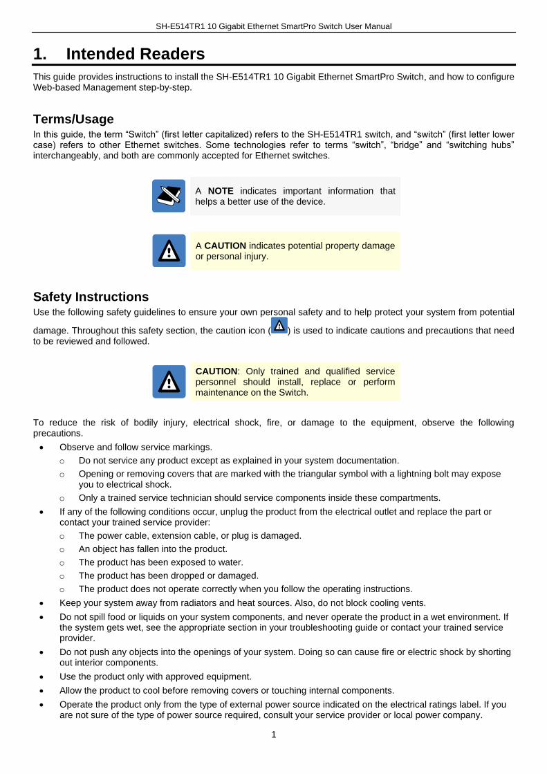
1. Intended Readers
This guide provides instructions to install the SH-E514TR1 10 Gigabit Ethernet SmartPro Switch, and how to configure Web-based Management step-by-step.
Terms/Usage In this guide, the term “Switch” (first letter capitalized) refers to the SH-E514TR1 switch, and “switch” (first letter lower case) refers to other Ethernet switches. Some technologies refer to terms “switch”, “bridge” and “switching hubs” interchangeably, and both are commonly accepted for Ethernet switches.
A NOTE indicates important information that helps a better use of the device.
A CAUTION indicates potential property damage or personal injury.
Safety Instructions Use the following safety guidelines to ensure your own personal safety and to help protect your system from potential
damage. Throughout this safety section, the caution icon ( ) is used to indicate cautions and precautions that need to be reviewed and followed.
CAUTION: Only trained and qualified service personnel should install, replace or perform maintenance on the Switch.
To reduce the risk of bodily injury, electrical shock, fire, or damage to the equipment, observe the following precautions.
Observe and follow service markings.
o Do not service any product except as explained in your system documentation.
o Opening or removing covers that are marked with the triangular symbol with a lightning bolt may expose you to electrical shock.
o Only a trained service technician should service components inside these compartments.
If any of the following conditions occur, unplug the product from the electrical outlet and replace the part or contact your trained service provider:
o The power cable, extension cable, or plug is damaged.
o An object has fallen into the product.
o The product has been exposed to water.
o The product has been dropped or damaged.
o The product does not operate correctly when you follow the operating instructions.
Keep your system away from radiators and heat sources. Also, do not block cooling vents.
Do not spill food or liquids on your system components, and never operate the product in a wet environment. If the system gets wet, see the appropriate section in your troubleshooting guide or contact your trained service provider.
Do not push any objects into the openings of your system. Doing so can cause fire or electric shock by shorting out interior components.
Use the product only with approved equipment.
Allow the product to cool before removing covers or touching internal components.
Operate the product only from the type of external power source indicated on the electrical ratings label. If you are not sure of the type of power source required, consult your service provider or local power company.

SH-E514TR1 10 Gigabit Ethernet SmartPro Switch User Manual
2
To help avoid damaging your system, be sure the voltage on the power supply is set to match the power available at your location:
o 115 volts (V)/60 hertz (Hz) in most of North and South America and some Far Eastern countries such as South Korea and Taiwan
o 100 V/50 Hz in eastern Japan and 100 V/60 Hz in western Japan
o 230 V/50 Hz in most of Europe, the Middle East, and the Far East
Also, be sure that attached devices are electrically rated to operate with the power available in your location.
Use only approved power cable(s). If you have not been provided with a power cable for your system or for any AC-powered option intended for your system, purchase a power cable that is approved for use in your country. The power cable must be rated for the product and for the voltage and current marked on the product's electrical ratings label. The voltage and current rating of the cable should be greater than the ratings marked on the product.
To help prevent electric shock, plug the system and peripheral power cables into properly grounded electrical outlets. These cables are equipped with three-prong plugs to help ensure proper grounding. Do not use adapter plugs or remove the grounding prong from a cable. If you must use an extension cable, use a 3-wire cable with properly grounded plugs.
Observe extension cable and power strip ratings. Make sure that the total ampere rating of all products plugged into the extension cable or power strip does not exceed 80 percent of the ampere ratings limit for the extension cable or power strip.
To help protect your system from sudden, transient increases and decreases in electrical power, use a surge suppressor, line conditioner, or uninterruptible power supply (UPS).
Position system cables and power cables carefully; route cables so that they cannot be stepped on or tripped over. Be sure that nothing rests on any cables.
Do not modify power cables or plugs. Consult a licensed electrician or your power company for site modifications. Always follow your local/national wiring rules.
When connecting or disconnecting power to hot-pluggable power supplies, if offered with your system, observe the following guidelines:
o Install the power supply before connecting the power cable to the power supply.
o Unplug the power cable before removing the power supply.
o If the system has multiple sources of power, disconnect power from the system by unplugging all power cables from the power supplies.
Move products with care; ensure that all casters and/or stabilizers are firmly connected to the system. Avoid sudden stops and uneven surfaces.
General Precautions for Rack-Mountable Products Observe the following precautions for rack stability and safety. Also, refer to the rack installation documentation accompanying the system and the rack for specific caution statements and procedures.
Systems are considered to be components in a rack. Thus, "component" refers to any system as well as to various peripherals or supporting hardware.
Before working on the rack, make sure that the stabilizers are secured to the rack, extended to the floor, and that the full weight of the rack rests on the floor. Install front and side stabilizers on a single rack or front stabilizers for joined multiple racks before working on the rack.
Always load the rack from the bottom up, and load the heaviest item in the rack first.
Make sure that the rack is level and stable before extending a component from the rack.
Use caution when pressing the component rail release latches and sliding a component into or out of a rack; the slide rails can pinch your fingers.
After a component is inserted into the rack, carefully extend the rail into a locking position, and then slide the component into the rack.
Do not overload the AC supply branch circuit that provides power to the rack. The total rack load should not exceed 80 percent of the branch circuit rating.
Ensure that proper airflow is provided to components in the rack.
Do not step on or stand on any component when servicing other components in a rack.

SH-E514TR1 10 Gigabit Ethernet SmartPro Switch User Manual
3
CAUTION: Never defeat the ground conductor or operate the equipment in the absence of a suitably installed ground conductor. Contact the appropriate electrical inspection authority or an electrician if you are uncertain that suitable grounding is available.
CAUTION: The system chassis must be positively grounded to the rack cabinet frame. Do not attempt to connect power to the system until grounding cables are connected. A qualified electrical inspector must inspect completed power and safety ground wiring. An energy hazard will exist if the safety ground cable is omitted or disconnected.
Protecting Against Electrostatic Discharge Static electricity can harm delicate components inside your system. To prevent static damage, discharge static electricity from your body before you touch any of the electronic components, such as the microprocessor. You can do so by periodically touching an unpainted metal surface on the chassis.
You can also take the following steps to prevent damage from electrostatic discharge (ESD):
1. When unpacking a static-sensitive component from its shipping carton, do not remove the component from the antistatic packing material until you are ready to install the component in your system. Just before unwrapping the antistatic packaging, be sure to discharge static electricity from your body.
2. When transporting a sensitive component, first place it in an antistatic container or packaging.
3. Handle all sensitive components in a static-safe area. If possible, use antistatic floor pads, workbench pads and an antistatic grounding strap.

SH-E514TR1 10 Gigabit Ethernet SmartPro Switch User Manual
4
2. Product Introduction
Thank you and congratulations on your purchase of SH-E514TR1 10 Gigabit Ethernet SmartPro Switch.
The product blends plug-and-play simplicity with exceptional value and reliability for small and medium-sized business (SMB) networking. All models are housed in a new style rack-mount metal case with easy-to-view front panel diagnostic LEDs, and provides advanced features including network security, traffic segmentation, QoS and versatile management.
Flexible Port Configurations. The Switch is the new generation of Web 10 Gigabit Ethernet Switch series. It
provides a variety of port counts that can operate at up to 10 Gbps wire speed.
Extensive Layer 2 Features. Implemented as complete L2 device, the Switch includes functions such as IGMP snooping, Spanning Tree, and 802.3ad LACP to enhance performance and network resiliency.
Traffic Segmentation, and QoS. The Switch supports 802.1Q VLAN standard tagging to enhance network security and performance. The Switch also support 802.1p priority queues, enabling users to run bandwidth-sensitive applications such as streaming multimedia by prioritizing that traffic in network. These functions allow the Switch to work seamlessly with VLAN and 802.1p traffic in the network.
Network Security. Storm Control can help to keep the network from being overwhelmed by abnormal traffic. Port Security is another simple but useful authentication method to maintain the network device integrity.
Versatile Management. The new generation of the Switch provides growing businesses with a simple and easy management of their network, using a Web-Based management interface that allows administrators to remotely control their network down to the port level.
In addition, users can utilize the SNMP MIB (Management Information Base) to poll the Switch for information about the status, or send out traps of abnormal events. SNMP support allows users to integrate the Switch with other third-party devices for management in an SNMP-enabled environment
Automated Fan Speed. The Switch has a built-in temperature sensor that will measure the internal temperature of the Switch and then automatically adjust the speed of the fans to either high-speed or low-speed.
SH-E514TR1 10 Gigabit Ethernet SmartPro Switch User Manual
5
3. Getting Started
The Switch can be managed through any port on the device by using the Web-based Management.
Each switch must be assigned its own IP Address, which is used for communication with the Web-based Management or a SNMP network manager. The PC should have an IP address in the same range as the switch. Each switch can allow up to four users to access the Web-Based Management concurrently.
After a successful physical installation, you can configure the Switch, monitor the network status, and display statistics using a web browser.
Recommended Web Browsers To be able to access the Web-based Management, it is recommended to use one of the following web browsers:
Internet Explorer 11
Firefox 43.0.4
Google Chrome 47.0
Connecting to the Switch You will need the following equipment to begin the web configuration of your device:
1. A PC with a RJ45 Ethernet connection
2. A standard Ethernet cable
Connect the Ethernet cable to any of the ports on the front panel of the switch and to the Ethernet port on the PC.
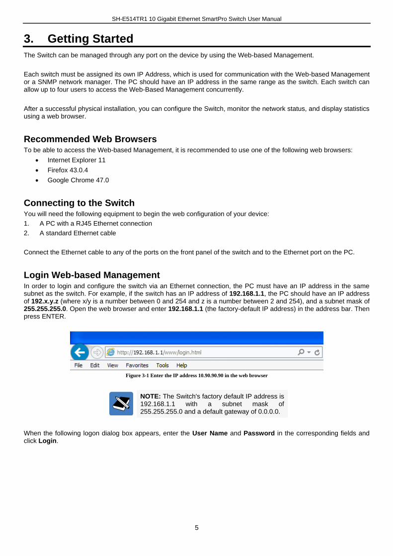
Login Web-based Management In order to login and configure the switch via an Ethernet connection, the PC must have an IP address in the same subnet as the switch. For example, if the switch has an IP address of 192.168.1.1, the PC should have an IP address of 192.x.y.z (where x/y is a number between 0 and 254 and z is a number between 2 and 254), and a subnet mask of 255.255.255.0. Open the web browser and enter 192.168.1.1 (the factory-default IP address) in the address bar. Then press ENTER.
Figure 3-1 Enter the IP address 10.90.90.90 in the web browser
NOTE: The Switch's factory default IP address is 192.168.1.1 with a subnet mask of 255.255.255.0 and a default gateway of 0.0.0.0.
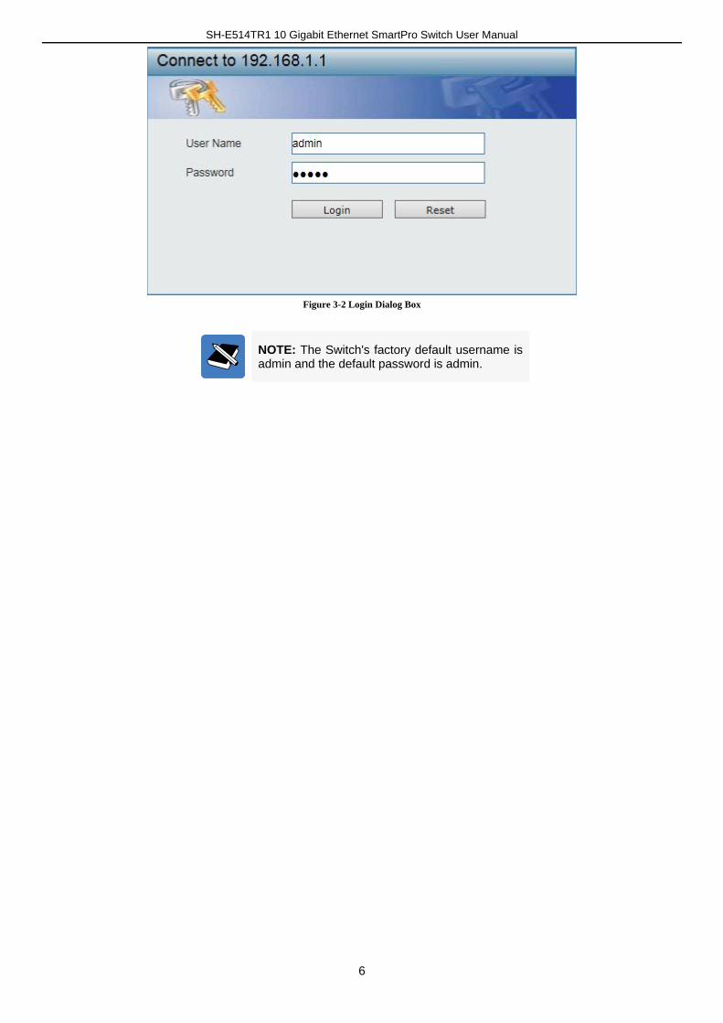
When the following logon dialog box appears, enter the User Name and Password in the corresponding fields and click Login.
SH-E514TR1 10 Gigabit Ethernet SmartPro Switch User Manual
6
Figure 3-2 Login Dialog Box
NOTE: The Switch's factory default username is admin and the default password is admin.
SH-E514TR1 10 Gigabit Ethernet SmartPro Switch User Manual
7
4. Web-based Management
The features and functions of the Switch can be configured for optimum use through the Web-based Management Utility.
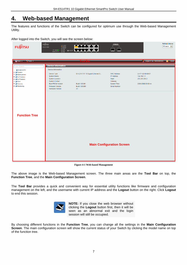
After logged into the Switch, you will see the screen below:
Figure 4-1 Web-based Management
The above image is the Web-based Management screen. The three main areas are the Tool Bar on top, the Function Tree, and the Main Configuration Screen.
The Tool Bar provides a quick and convenient way for essential utility functions like firmware and configuration management on the left, and the username with current IP address and the Logout button on the right. Click Logout to end this session.
NOTE: If you close the web browser without clicking the Logout button first, then it will be seen as an abnormal exit and the login session will still be occupied.
By choosing different functions in the Function Tree, you can change all the settings in the Main Configuration Screen. The main configuration screen will show the current status of your Switch by clicking the model name on top of the function tree.
Function Tree
Main Configuration Screen
Tool Bar
SH-E514TR1 10 Gigabit Ethernet SmartPro Switch User Manual
8
5. Tool Bar
Save The Save Menu provides the Save Configuration function.
Figure 5-1 Save
Save Configuration
Select to save the entire configuration changes you have made to the device to switch’s non-volatile RAM.
Figure 5-2 Save Configuration
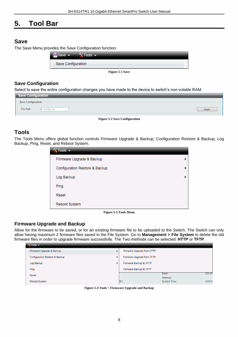
Tools The Tools Menu offers global function controls Firmware Upgrade & Backup, Configuration Restore & Backup, Log Backup, Ping, Reset, and Reboot System.
Figure 5-3 Tools Menu
Firmware Upgrade and Backup
Allow for the firmware to be saved, or for an existing firmware file to be uploaded to the Switch. The Switch can only allow having maximum 2 firmware files saved in the File System. Go to Management > File System to delete the old firmware files in order to upgrade firmware successfully. The Two methods can be selected: HTTP or TFTP.
Figure 5-4 Tools > Firmware Upgrade and Backup
SH-E514TR1 10 Gigabit Ethernet SmartPro Switch User Manual
9
Firmware Upgrade from HTTP
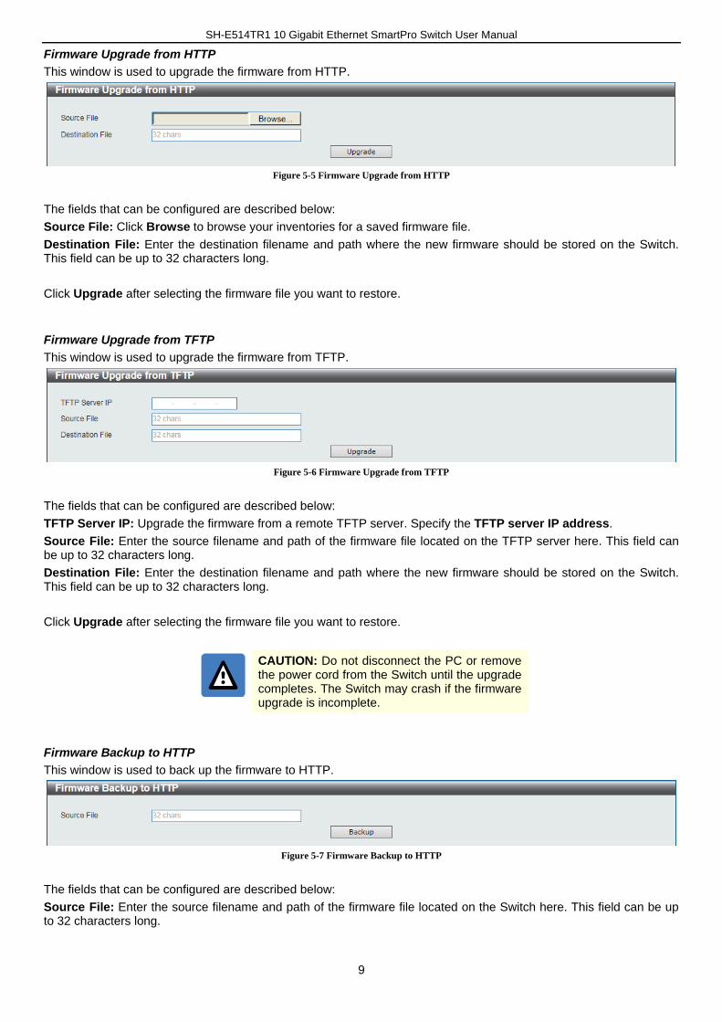
This window is used to upgrade the firmware from HTTP.
Figure 5-5 Firmware Upgrade from HTTP
The fields that can be configured are described below:
Source File: Click Browse to browse your inventories for a saved firmware file.
Destination File: Enter the destination filename and path where the new firmware should be stored on the Switch. This field can be up to 32 characters long.
Click Upgrade after selecting the firmware file you want to restore.
Firmware Upgrade from TFTP
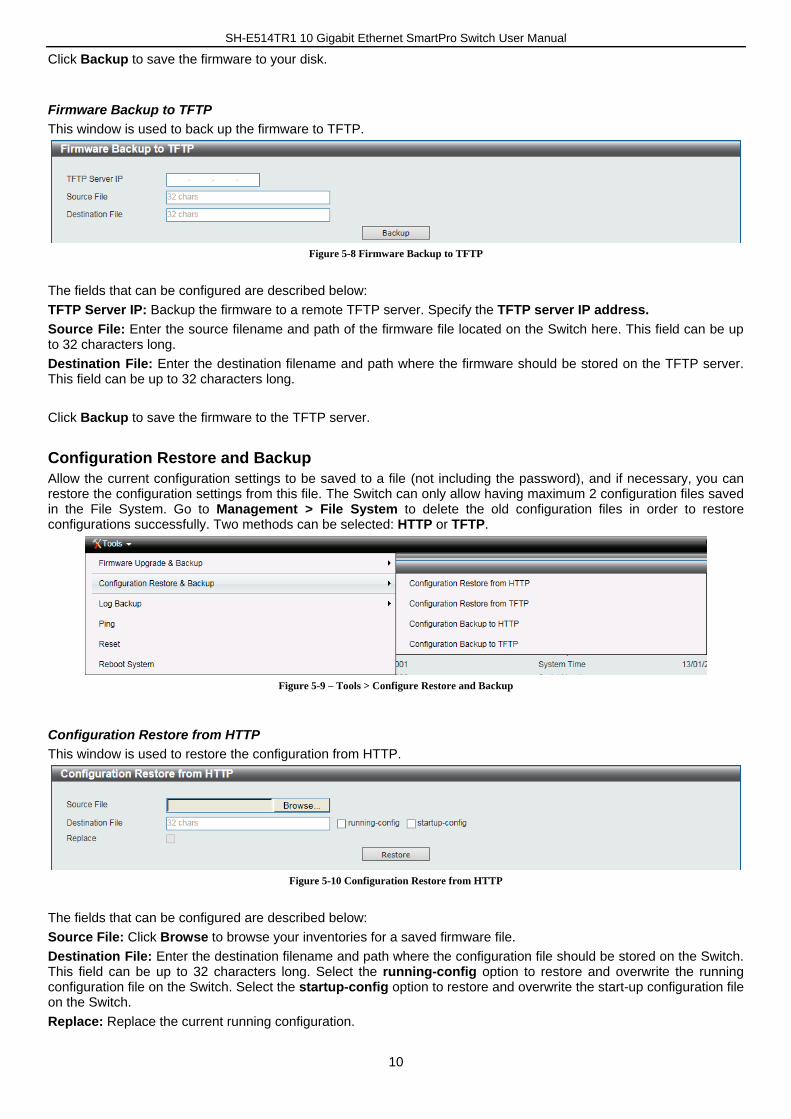
This window is used to upgrade the firmware from TFTP.
Figure 5-6 Firmware Upgrade from TFTP
The fields that can be configured are described below:
TFTP Server IP: Upgrade the firmware from a remote TFTP server. Specify the TFTP server IP address.
Source File: Enter the source filename and path of the firmware file located on the TFTP server here. This field can be up to 32 characters long.
Destination File: Enter the destination filename and path where the new firmware should be stored on the Switch. This field can be up to 32 characters long.
Click Upgrade after selecting the firmware file you want to restore.
CAUTION: Do not disconnect the PC or remove the power cord from the Switch until the upgrade completes. The Switch may crash if the firmware upgrade is incomplete.
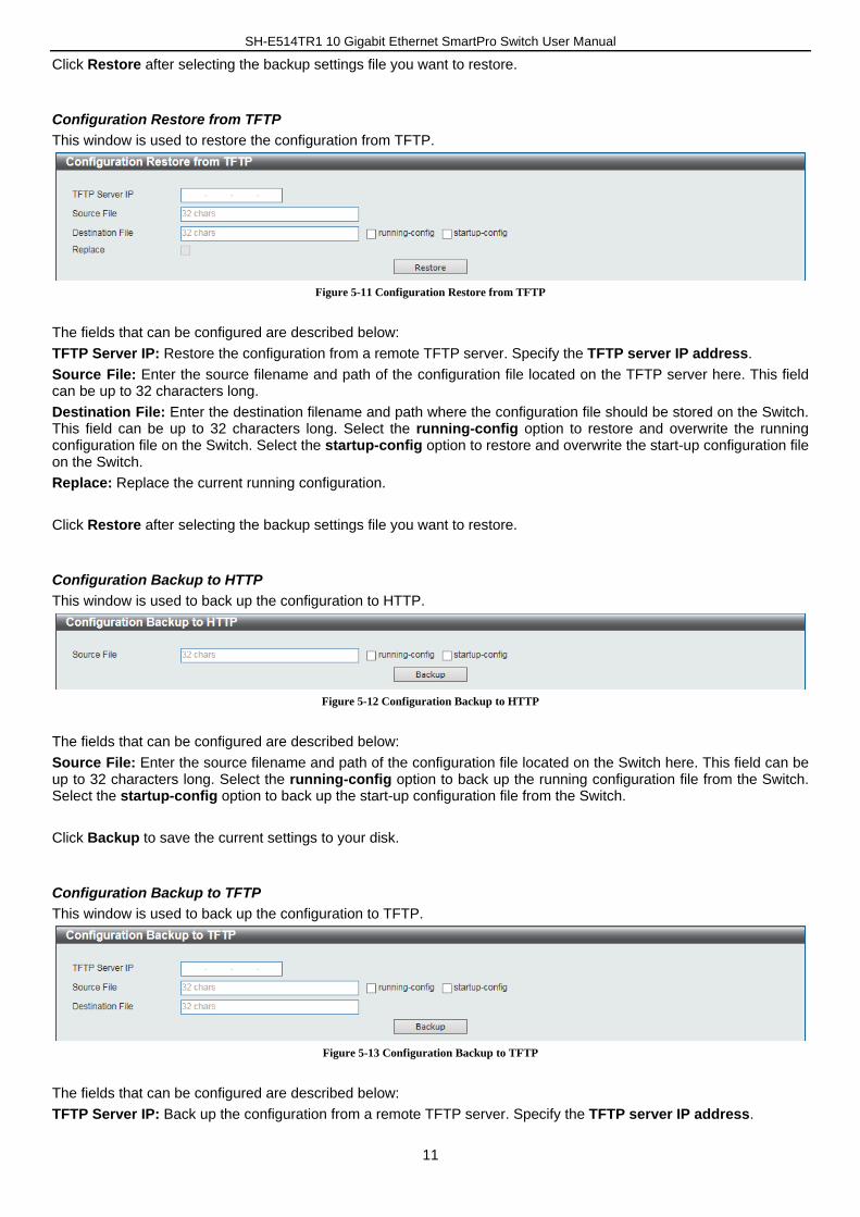
Firmware Backup to HTTP
This window is used to back up the firmware to HTTP.
Figure 5-7 Firmware Backup to HTTP
The fields that can be configured are described below:
Source File: Enter the source filename and path of the firmware file located on the Switch here. This field can be up to 32 characters long.
SH-E514TR1 10 Gigabit Ethernet SmartPro Switch User Manual
10
Click Backup to save the firmware to your disk.
Firmware Backup to TFTP
This window is used to back up the firmware to TFTP.
Figure 5-8 Firmware Backup to TFTP
The fields that can be configured are described below:
TFTP Server IP: Backup the firmware to a remote TFTP server. Specify the TFTP server IP address.
Source File: Enter the source filename and path of the firmware file located on the Switch here. This field can be up to 32 characters long.
Destination File: Enter the destination filename and path where the firmware should be stored on the TFTP server. This field can be up to 32 characters long.
Click Backup to save the firmware to the TFTP server.
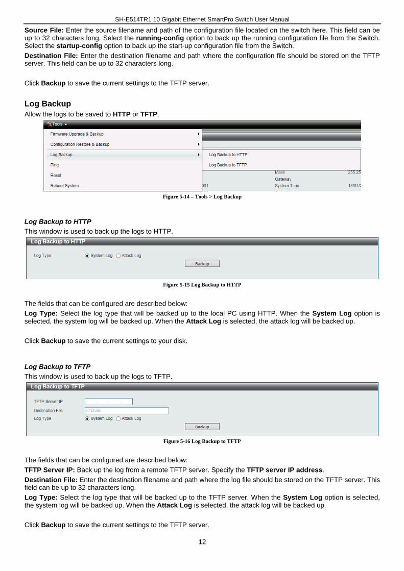
Configuration Restore and Backup
Allow the current configuration settings to be saved to a file (not including the password), and if necessary, you can restore the configuration settings from this file. The Switch can only allow having maximum 2 configuration files saved in the File System. Go to Management > File System to delete the old configuration files in order to restore configurations successfully. Two methods can be selected: HTTP or TFTP.
Figure 5-9 – Tools > Configure Restore and Backup
Configuration Restore from HTTP
This window is used to restore the configuration from HTTP.
Figure 5-10 Configuration Restore from HTTP
The fields that can be configured are described below:
Source File: Click Browse to browse your inventories for a saved firmware file.
Destination File: Enter the destination filename and path where the configuration file should be stored on the Switch. This field can be up to 32 characters long. Select the running-config option to restore and overwrite the running configuration file on the Switch. Select the startup-config option to restore and overwrite the start-up configuration file on the Switch.
Replace: Replace the current running configuration.
SH-E514TR1 10 Gigabit Ethernet SmartPro Switch User Manual
11
Click Restore after selecting the backup settings file you want to restore.
Configuration Restore from TFTP
This window is used to restore the configuration from TFTP.
Figure 5-11 Configuration Restore from TFTP
The fields that can be configured are described below:
TFTP Server IP: Restore the configuration from a remote TFTP server. Specify the TFTP server IP address.
Source File: Enter the source filename and path of the configuration file located on the TFTP server here. This field can be up to 32 characters long.
Destination File: Enter the destination filename and path where the configuration file should be stored on the Switch. This field can be up to 32 characters long. Select the running-config option to restore and overwrite the running configuration file on the Switch. Select the startup-config option to restore and overwrite the start-up configuration file on the Switch.
Replace: Replace the current running configuration.
Click Restore after selecting the backup settings file you want to restore.
Configuration Backup to HTTP
This window is used to back up the configuration to HTTP.
Figure 5-12 Configuration Backup to HTTP
The fields that can be configured are described below:
Source File: Enter the source filename and path of the configuration file located on the Switch here. This field can be up to 32 characters long. Select the running-config option to back up the running configuration file from the Switch. Select the startup-config option to back up the start-up configuration file from the Switch.
Click Backup to save the current settings to your disk.
Configuration Backup to TFTP
This window is used to back up the configuration to TFTP.
Figure 5-13 Configuration Backup to TFTP
The fields that can be configured are described below:
TFTP Server IP: Back up the configuration from a remote TFTP server. Specify the TFTP server IP address.
SH-E514TR1 10 Gigabit Ethernet SmartPro Switch User Manual
12
Source File: Enter the source filename and path of the configuration file located on the switch here. This field can be up to 32 characters long. Select the running-config option to back up the running configuration file from the Switch. Select the startup-config option to back up the start-up configuration file from the Switch.
Destination File: Enter the destination filename and path where the configuration file should be stored on the TFTP server. This field can be up to 32 characters long.
Click Backup to save the current settings to the TFTP server.
Log Backup
Allow the logs to be saved to HTTP or TFTP.
Figure 5-14 – Tools > Log Backup
Log Backup to HTTP
This window is used to back up the logs to HTTP.
Figure 5-15 Log Backup to HTTP
The fields that can be configured are described below:
Log Type: Select the log type that will be backed up to the local PC using HTTP. When the System Log option is selected, the system log will be backed up. When the Attack Log is selected, the attack log will be backed up.
Click Backup to save the current settings to your disk.
Log Backup to TFTP
This window is used to back up the logs to TFTP.
Figure 5-16 Log Backup to TFTP
The fields that can be configured are described below:
TFTP Server IP: Back up the log from a remote TFTP server. Specify the TFTP server IP address.
Destination File: Enter the destination filename and path where the log file should be stored on the TFTP server. This field can be up to 32 characters long.
Log Type: Select the log type that will be backed up to the TFTP server. When the System Log option is selected, the system log will be backed up. When the Attack Log is selected, the attack log will be backed up.
Click Backup to save the current settings to the TFTP server.
SH-E514TR1 10 Gigabit Ethernet SmartPro Switch User Manual
13
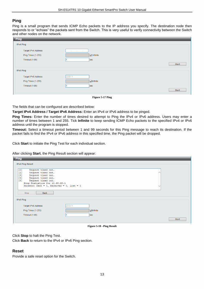
Ping
Ping is a small program that sends ICMP Echo packets to the IP address you specify. The destination node then responds to or “echoes” the packets sent from the Switch. This is very useful to verify connectivity between the Switch and other nodes on the network.
Figure 5-17 Ping
The fields that can be configured are described below:
Target IPv4 Address / Target IPv6 Address: Enter an IPv4 or IPv6 address to be pinged.
Ping Times: Enter the number of times desired to attempt to Ping the IPv4 or IPv6 address. Users may enter a number of times between 1 and 255. Tick Infinite to keep sending ICMP Echo packets to the specified IPv4 or IPv6 address until the program is stopped.
Timeout: Select a timeout period between 1 and 99 seconds for this Ping message to reach its destination. If the packet fails to find the IPv4 or IPv6 address in this specified time, the Ping packet will be dropped.
Click Start to initiate the Ping Test for each individual section.
After clicking Start, the Ping Result section will appear:
Figure 5-18 –Ping Result
Click Stop to halt the Ping Test.
Click Back to return to the IPv4 or IPv6 Ping section.
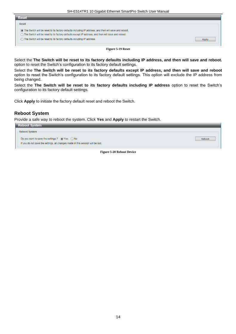
Reset
Provide a safe reset option for the Switch.
SH-E514TR1 10 Gigabit Ethernet SmartPro Switch User Manual
14
Figure 5-19 Reset
Select the The Switch will be reset to its factory defaults including IP address, and then will save and reboot. option to reset the Switch’s configuration to its factory default settings.
Select the The Switch will be reset to its factory defaults except IP address, and then will save and reboot option to reset the Switch’s configuration to its factory default settings. This option will exclude the IP address from being changed.
Select the The Switch will be reset to its factory defaults including IP address option to reset the Switch’s configuration to its factory default settings.
Click Apply to initiate the factory default reset and reboot the Switch.
Reboot System
Provide a safe way to reboot the system. Click Yes and Apply to restart the Switch.
Figure 5-20 Reboot Device

SH-E514TR1 10 Gigabit Ethernet SmartPro Switch User Manual
15
6. Device Information
This window displays the Device Information. It appears automatically when you log in the Switch. To return to the Device Information window after viewing other windows, click SH-E514TR1 in the Function Tree.
Figure 6-1 – Device Information
SH-E514TR1 10 Gigabit Ethernet SmartPro Switch User Manual
16
7. System
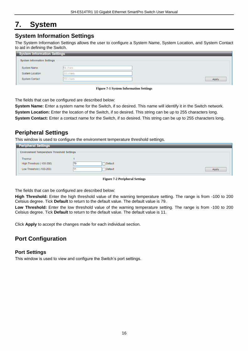
System Information Settings The System Information Settings allows the user to configure a System Name, System Location, and System Contact to aid in defining the Switch.
Figure 7-1 System Information Settings
The fields that can be configured are described below:
System Name: Enter a system name for the Switch, if so desired. This name will identify it in the Switch network.
System Location: Enter the location of the Switch, if so desired. This string can be up to 255 characters long.
System Contact: Enter a contact name for the Switch, if so desired. This string can be up to 255 characters long.
Peripheral Settings This window is used to configure the environment temperature threshold settings.
Figure 7-2 Peripheral Settings
The fields that can be configured are described below:
High Threshold: Enter the high threshold value of the warning temperature setting. The range is from -100 to 200 Celsius degree. Tick Default to return to the default value. The default value is 79.
Low Threshold: Enter the low threshold value of the warning temperature setting. The range is from -100 to 200 Celsius degree. Tick Default to return to the default value. The default value is 11.
Click Apply to accept the changes made for each individual section.
Port Configuration
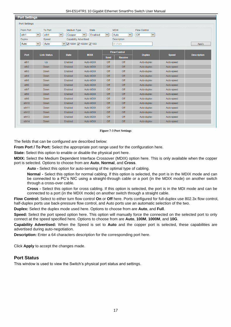
Port Settings
This window is used to view and configure the Switch’s port settings.
SH-E514TR1 10 Gigabit Ethernet SmartPro Switch User Manual
17
Figure 7-3 Port Settings
The fields that can be configured are described below:
From Port / To Port: Select the appropriate port range used for the configuration here.
State: Select this option to enable or disable the physical port here.
MDIX: Select the Medium Dependent Interface Crossover (MDIX) option here. This is only available when the copper port is selected. Options to choose from are Auto, Normal, and Cross.
Auto - Select this option for auto-sensing of the optimal type of cabling.
Normal - Select this option for normal cabling. If this option is selected, the port is in the MDIX mode and can be connected to a PC’s NIC using a straight-through cable or a port (in the MDIX mode) on another switch through a cross-over cable.
Cross - Select this option for cross cabling. If this option is selected, the port is in the MDI mode and can be connected to a port (in the MDIX mode) on another switch through a straight cable.
Flow Control: Select to either turn flow control On or Off here. Ports configured for full-duplex use 802.3x flow control, half-duplex ports use back-pressure flow control, and Auto ports use an automatic selection of the two.
Duplex: Select the duplex mode used here. Options to choose from are Auto, and Full.
Speed: Select the port speed option here. This option will manually force the connected on the selected port to only connect at the speed specified here. Options to choose from are Auto, 100M, 1000M, and 10G.
Capability Advertised: When the Speed is set to Auto and the copper port is selected, these capabilities are advertised during auto-negotiation.
Description: Enter a 64 characters description for the corresponding port here.
Click Apply to accept the changes made.
Port Status
This window is used to view the Switch’s physical port status and settings.
SH-E514TR1 10 Gigabit Ethernet SmartPro Switch User Manual
18
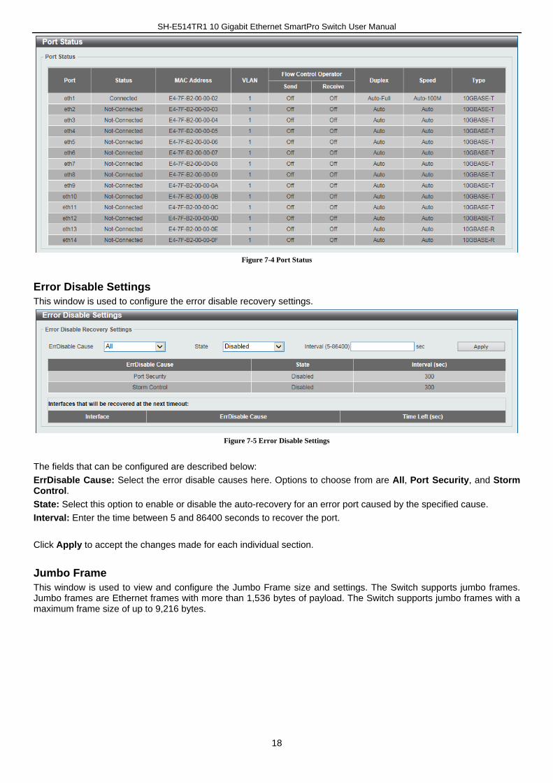
Figure 7-4 Port Status
Error Disable Settings
This window is used to configure the error disable recovery settings.
Figure 7-5 Error Disable Settings
The fields that can be configured are described below:
ErrDisable Cause: Select the error disable causes here. Options to choose from are All, Port Security, and Storm Control.
State: Select this option to enable or disable the auto-recovery for an error port caused by the specified cause.
Interval: Enter the time between 5 and 86400 seconds to recover the port.
Click Apply to accept the changes made for each individual section.
Jumbo Frame
This window is used to view and configure the Jumbo Frame size and settings. The Switch supports jumbo frames. Jumbo frames are Ethernet frames with more than 1,536 bytes of payload. The Switch supports jumbo frames with a maximum frame size of up to 9,216 bytes.
SH-E514TR1 10 Gigabit Ethernet SmartPro Switch User Manual
19
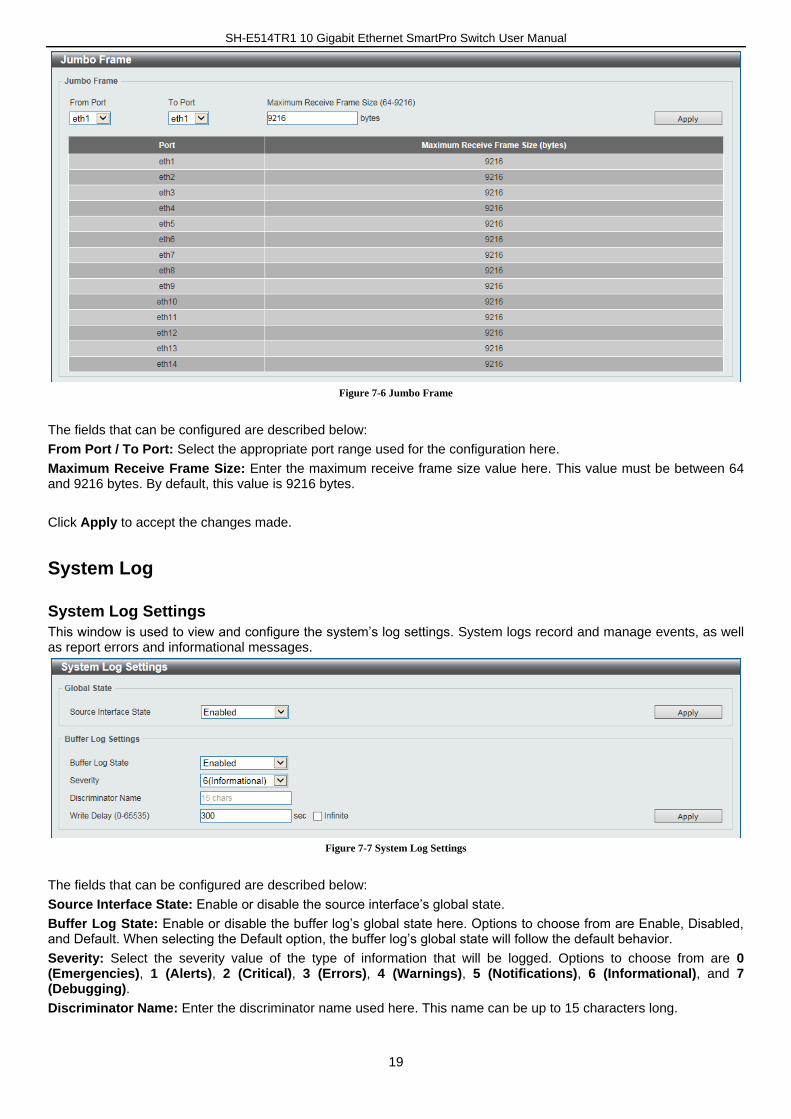
Figure 7-6 Jumbo Frame
The fields that can be configured are described below:
From Port / To Port: Select the appropriate port range used for the configuration here.
Maximum Receive Frame Size: Enter the maximum receive frame size value here. This value must be between 64 and 9216 bytes. By default, this value is 9216 bytes.
Click Apply to accept the changes made.
System Log
System Log Settings
This window is used to view and configure the system’s log settings. System logs record and manage events, as well as report errors and informational messages.
Figure 7-7 System Log Settings
The fields that can be configured are described below:
Source Interface State: Enable or disable the source interface’s global state.
Buffer Log State: Enable or disable the buffer log’s global state here. Options to choose from are Enable, Disabled, and Default. When selecting the Default option, the buffer log’s global state will follow the default behavior.
Severity: Select the severity value of the type of information that will be logged. Options to choose from are 0 (Emergencies), 1 (Alerts), 2 (Critical), 3 (Errors), 4 (Warnings), 5 (Notifications), 6 (Informational), and 7 (Debugging).
Discriminator Name: Enter the discriminator name used here. This name can be up to 15 characters long.
SH-E514TR1 10 Gigabit Ethernet SmartPro Switch User Manual
20
Write Delay: Enter the interval for periodic writing of the logging buffer to FLASH. This value must be between 0 and 65535 seconds. By default, this value is 300 seconds. Tick Infinite to disable the write delay feature.
Click Apply to accept the changes made for each individual section.
System Log Discriminator Settings
This window is used to view and configure the system log’s discriminator settings.
Figure 7-8 System Log Discriminator Settings
The fields that can be configured are described below:
Discriminator Name: Enter the discriminator name here. This name can be up to 15 characters long.
Action: Select the facility’s behavior option and the type of facility that will be associated with the selected behavior here. Behavior options to choose from are Drops and Includes.
Severity: Select the severity behavior option and the value of the type of information that will be logged. Behavior options to choose from are Drops and Includes. Severity value options to choose from are 0 (Emergencies), 1 (Alerts), 2 (Critical), 3 (Errors), 4 (Warnings), 5 (Notifications), 6 (Informational), and 7 (Debugging).
Click Apply to accept the changes made.
Click Delete to remove the specified entry.
System Log Server Settings
This window is used to view and configure system log’s server settings.
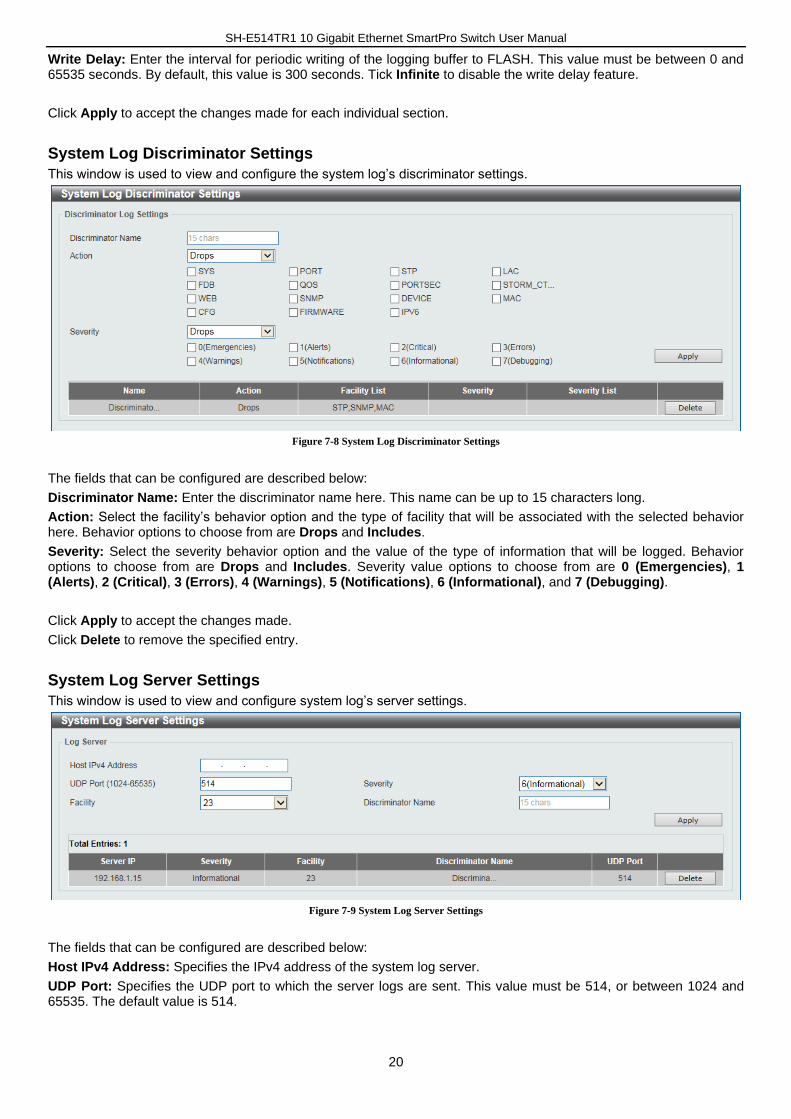
Figure 7-9 System Log Server Settings
The fields that can be configured are described below:
Host IPv4 Address: Specifies the IPv4 address of the system log server.
UDP Port: Specifies the UDP port to which the server logs are sent. This value must be 514, or between 1024 and 65535. The default value is 514.
SH-E514TR1 10 Gigabit Ethernet SmartPro Switch User Manual
21
Severity: Select the severity value of the type of information that will be logged. Options to choose from are 0 (Emergencies), 1 (Alerts), 2 (Critical), 3 (Errors), 4 (Warnings), 5 (Notifications), 6 (Informational), and 7 (Debugging).
Facility: Select the facility value here. Options to choose from are 0 to 23.
Discriminator Name: Enter the discriminator name here. This name can be up to 15 characters long.
Click Apply to accept the changes made.
Click Delete to remove the specified entry.
System Log
This window is used to view and clear the system log. The maximum number of entries that will be displayed in this table is 1,000. The index number can go up to 90,000. When this log is full, older entries will be removed and replaced by newer ones.
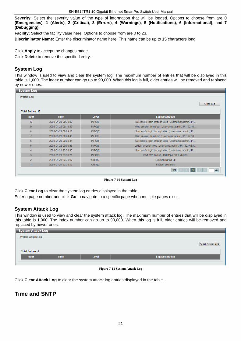
Figure 7-10 System Log
Click Clear Log to clear the system log entries displayed in the table.
Enter a page number and click Go to navigate to a specific page when multiple pages exist.
System Attack Log
This window is used to view and clear the system attack log. The maximum number of entries that will be displayed in this table is 1,000. The index number can go up to 90,000. When this log is full, older entries will be removed and replaced by newer ones.
Figure 7-11 System Attack Log
Click Clear Attack Log to clear the system attack log entries displayed in the table.
Time and SNTP
SH-E514TR1 10 Gigabit Ethernet SmartPro Switch User Manual
22
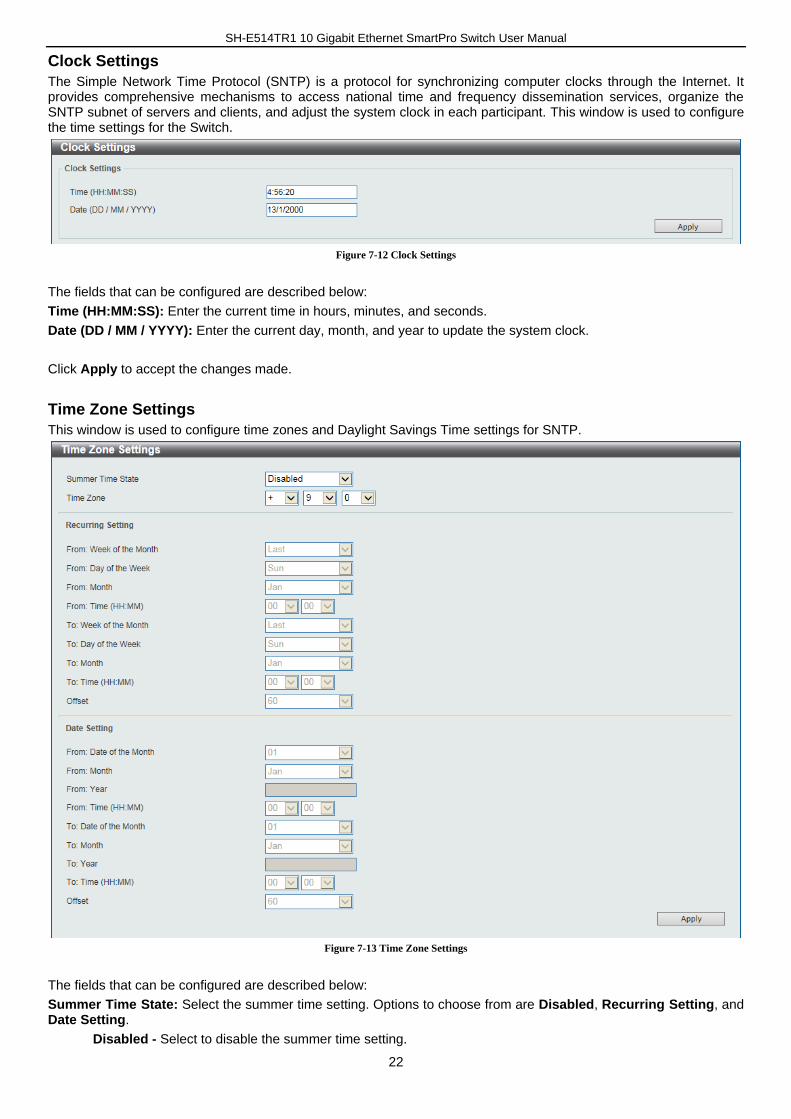
Clock Settings
The Simple Network Time Protocol (SNTP) is a protocol for synchronizing computer clocks through the Internet. It provides comprehensive mechanisms to access national time and frequency dissemination services, organize the SNTP subnet of servers and clients, and adjust the system clock in each participant. This window is used to configure the time settings for the Switch.
Figure 7-12 Clock Settings
The fields that can be configured are described below:
Time (HH:MM:SS): Enter the current time in hours, minutes, and seconds.
Date (DD / MM / YYYY): Enter the current day, month, and year to update the system clock.
Click Apply to accept the changes made.
Time Zone Settings
This window is used to configure time zones and Daylight Savings Time settings for SNTP.
Figure 7-13 Time Zone Settings
The fields that can be configured are described below:
Summer Time State: Select the summer time setting. Options to choose from are Disabled, Recurring Setting, and Date Setting.
Disabled - Select to disable the summer time setting.
SH-E514TR1 10 Gigabit Ethernet SmartPro Switch User Manual
23
Recurring Setting - Select to configure the summer time that should start and end on the specified week day of the specified month.
Date Setting - Select to configure the summer time that should start and end on the specified date of the specified month.
Time Zone: Select to specify your local time zone’s offset from Coordinated Universal Time (UTC).
From: Week of the Month: Select week of the month that summer time will start.
From: Day of the Week: Select the day of the week that summer time will start.
From: Month: Select the month that summer time will start.
From: Time (HH:MM): Select the time of the day that summer time will start.
To: Week of the Month: Select week of the month that summer time will end.
To: Day of the Week: Select the day of the week that summer time will end.
To: Month: Select the month that summer time will end.
To: Time (HH:MM): Select the time of the day that summer time will end.
Offset: Enter the number of minutes to add during summer time. The default value is 60. The range of this offset is 30, 60, 90 and 120.
From: Date of the Month: Select date of the month that summer time will start.
From: Month: Select the month that summer time will start.
From: Year: Enter the year that the summer time will start.
From: Time (HH:MM): Select the time of the day that summer time will start.
To: Date of the Month: Select date of the month that summer time will end.
To: Month: Select the month that summer time will end.
To: Year: Enter the year that the summer time will end.
To: Time (HH:MM): Select the time of the day that summer time will end.
Offset: Enter the number of minutes to add during summer time. The default value is 60. The range of this offset is 30, 60, 90 and 120.
Click Apply to accept the changes made.
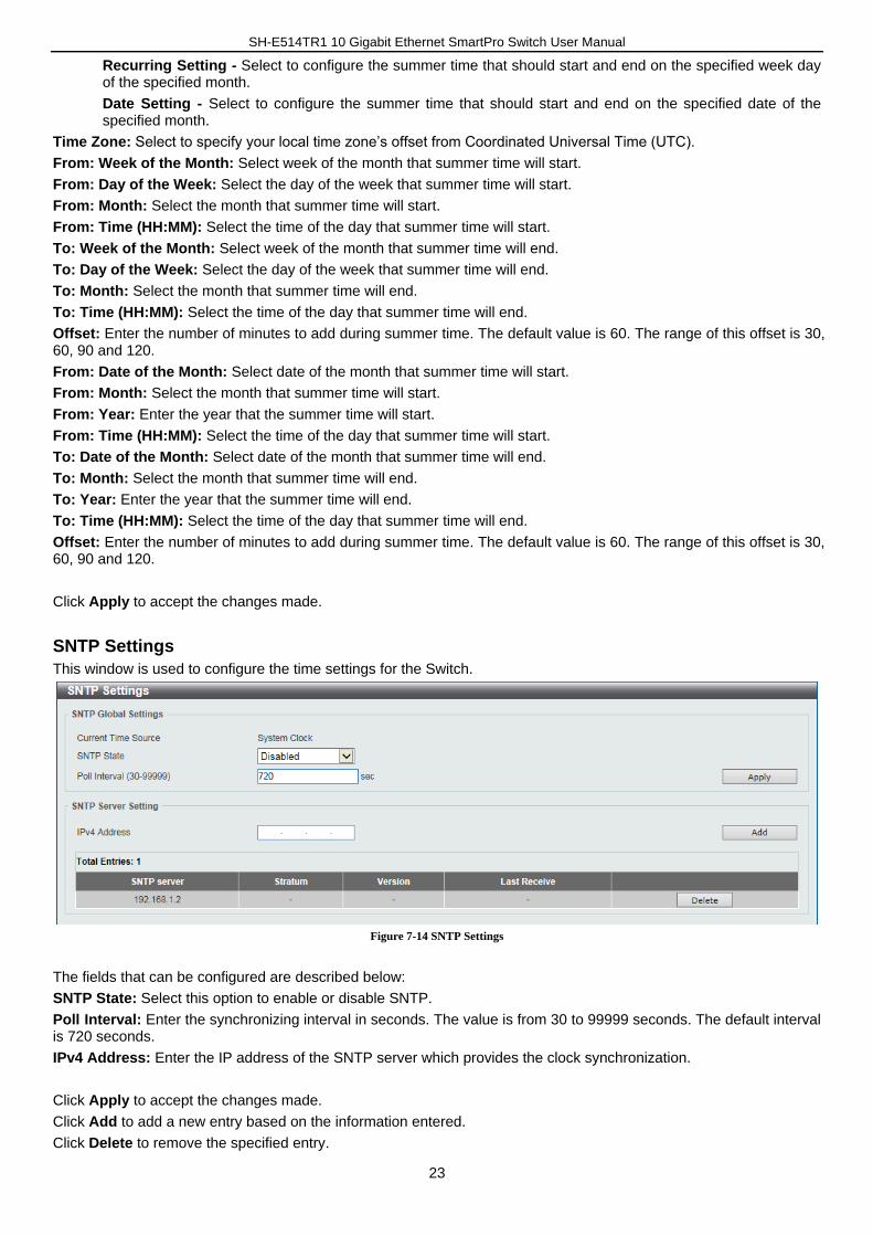
SNTP Settings
This window is used to configure the time settings for the Switch.
Figure 7-14 SNTP Settings
The fields that can be configured are described below:
SNTP State: Select this option to enable or disable SNTP.
Poll Interval: Enter the synchronizing interval in seconds. The value is from 30 to 99999 seconds. The default interval is 720 seconds.
IPv4 Address: Enter the IP address of the SNTP server which provides the clock synchronization.
Click Apply to accept the changes made.
Click Add to add a new entry based on the information entered.
Click Delete to remove the specified entry.
SH-E514TR1 10 Gigabit Ethernet SmartPro Switch User Manual
24
8. Management
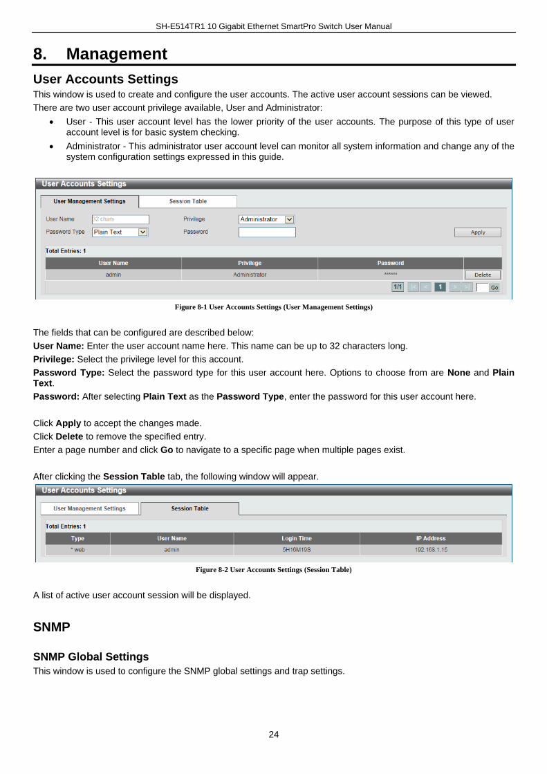
User Accounts Settings This window is used to create and configure the user accounts. The active user account sessions can be viewed.
There are two user account privilege available, User and Administrator:
User - This user account level has the lower priority of the user accounts. The purpose of this type of user account level is for basic system checking.
Administrator - This administrator user account level can monitor all system information and change any of the system configuration settings expressed in this guide.
Figure 8-1 User Accounts Settings (User Management Settings)
The fields that can be configured are described below:
User Name: Enter the user account name here. This name can be up to 32 characters long.
Privilege: Select the privilege level for this account.
Password Type: Select the password type for this user account here. Options to choose from are None and Plain Text.
Password: After selecting Plain Text as the Password Type, enter the password for this user account here.
Click Apply to accept the changes made.
Click Delete to remove the specified entry.
Enter a page number and click Go to navigate to a specific page when multiple pages exist.
After clicking the Session Table tab, the following window will appear.
Figure 8-2 User Accounts Settings (Session Table)
A list of active user account session will be displayed.
SNMP
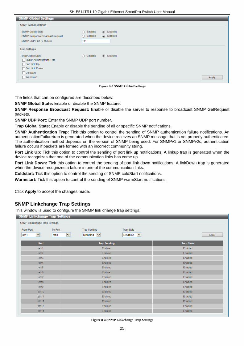
SNMP Global Settings
This window is used to configure the SNMP global settings and trap settings.
SH-E514TR1 10 Gigabit Ethernet SmartPro Switch User Manual
25
Figure 8-3 SNMP Global Settings
The fields that can be configured are described below:
SNMP Global State: Enable or disable the SNMP feature.
SNMP Response Broadcast Request: Enable or disable the server to response to broadcast SNMP GetRequest packets.
SNMP UDP Port: Enter the SNMP UDP port number.
Trap Global State: Enable or disable the sending of all or specific SNMP notifications.
SNMP Authentication Trap: Tick this option to control the sending of SNMP authentication failure notifications. An authenticationFailuretrap is generated when the device receives an SNMP message that is not properly authenticated. The authentication method depends on the version of SNMP being used. For SNMPv1 or SNMPv2c, authentication failure occurs if packets are formed with an incorrect community string.
Port Link Up: Tick this option to control the sending of port link up notifications. A linkup trap is generated when the device recognizes that one of the communication links has come up.
Port Link Down: Tick this option to control the sending of port link down notifications. A linkDown trap is generated when the device recognizes a failure in one of the communication links.
Coldstart: Tick this option to control the sending of SNMP coldStart notifications.
Warmstart: Tick this option to control the sending of SNMP warmStart notifications.
Click Apply to accept the changes made.
SNMP Linkchange Trap Settings
This window is used to configure the SNMP link change trap settings.
Figure 8-4 SNMP Linkchange Trap Settings
SH-E514TR1 10 Gigabit Ethernet SmartPro Switch User Manual
26
The fields that can be configured are described below:
From Port / To Port: Select the appropriate port range used for the configuration here.
Trap Sending: Enable or disable the sending of the SNMP notification traps that is generated by the system.
Trap State: Enable or disable the SNMP link change trap.
Click Apply to accept the changes made.
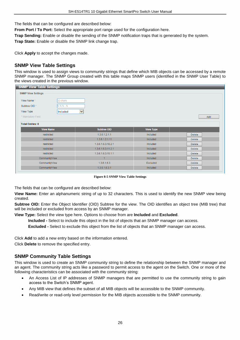
SNMP View Table Settings
This window is used to assign views to community strings that define which MIB objects can be accessed by a remote SNMP manager. The SNMP Group created with this table maps SNMP users (identified in the SNMP User Table) to the views created in the previous window.
Figure 8-5 SNMP View Table Settings
The fields that can be configured are described below:
View Name: Enter an alphanumeric string of up to 32 characters. This is used to identify the new SNMP view being created.
Subtree OID: Enter the Object Identifier (OID) Subtree for the view. The OID identifies an object tree (MIB tree) that will be included or excluded from access by an SNMP manager.
View Type: Select the view type here. Options to choose from are Included and Excluded.
Included - Select to include this object in the list of objects that an SNMP manager can access.
Excluded - Select to exclude this object from the list of objects that an SNMP manager can access.
Click Add to add a new entry based on the information entered.
Click Delete to remove the specified entry.
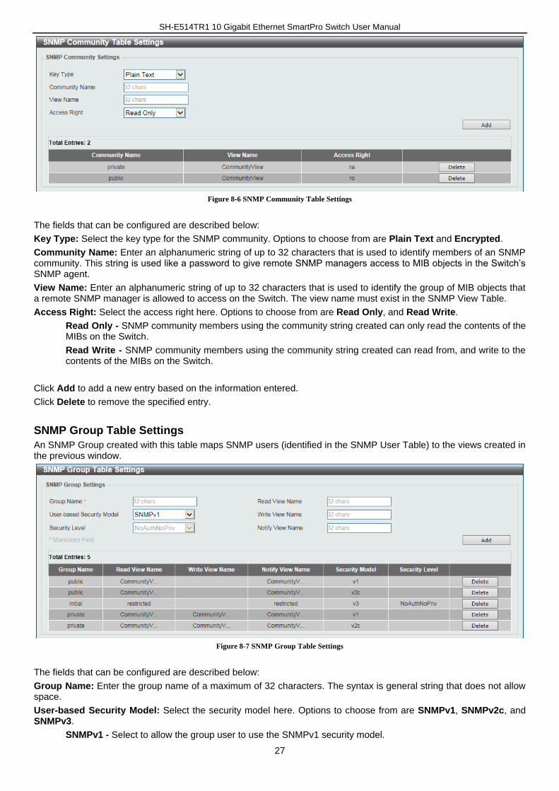
SNMP Community Table Settings
This window is used to create an SNMP community string to define the relationship between the SNMP manager and an agent. The community string acts like a password to permit access to the agent on the Switch. One or more of the following characteristics can be associated with the community string:
An Access List of IP addresses of SNMP managers that are permitted to use the community string to gain access to the Switch’s SNMP agent.
Any MIB view that defines the subset of all MIB objects will be accessible to the SNMP community.
Read/write or read-only level permission for the MIB objects accessible to the SNMP community.
SH-E514TR1 10 Gigabit Ethernet SmartPro Switch User Manual
27
Figure 8-6 SNMP Community Table Settings
The fields that can be configured are described below:
Key Type: Select the key type for the SNMP community. Options to choose from are Plain Text and Encrypted.
Community Name: Enter an alphanumeric string of up to 32 characters that is used to identify members of an SNMP community. This string is used like a password to give remote SNMP managers access to MIB objects in the Switch’s SNMP agent.
View Name: Enter an alphanumeric string of up to 32 characters that is used to identify the group of MIB objects that a remote SNMP manager is allowed to access on the Switch. The view name must exist in the SNMP View Table.
Access Right: Select the access right here. Options to choose from are Read Only, and Read Write.
Read Only - SNMP community members using the community string created can only read the contents of the MIBs on the Switch.
Read Write - SNMP community members using the community string created can read from, and write to the contents of the MIBs on the Switch.
Click Add to add a new entry based on the information entered.
Click Delete to remove the specified entry.
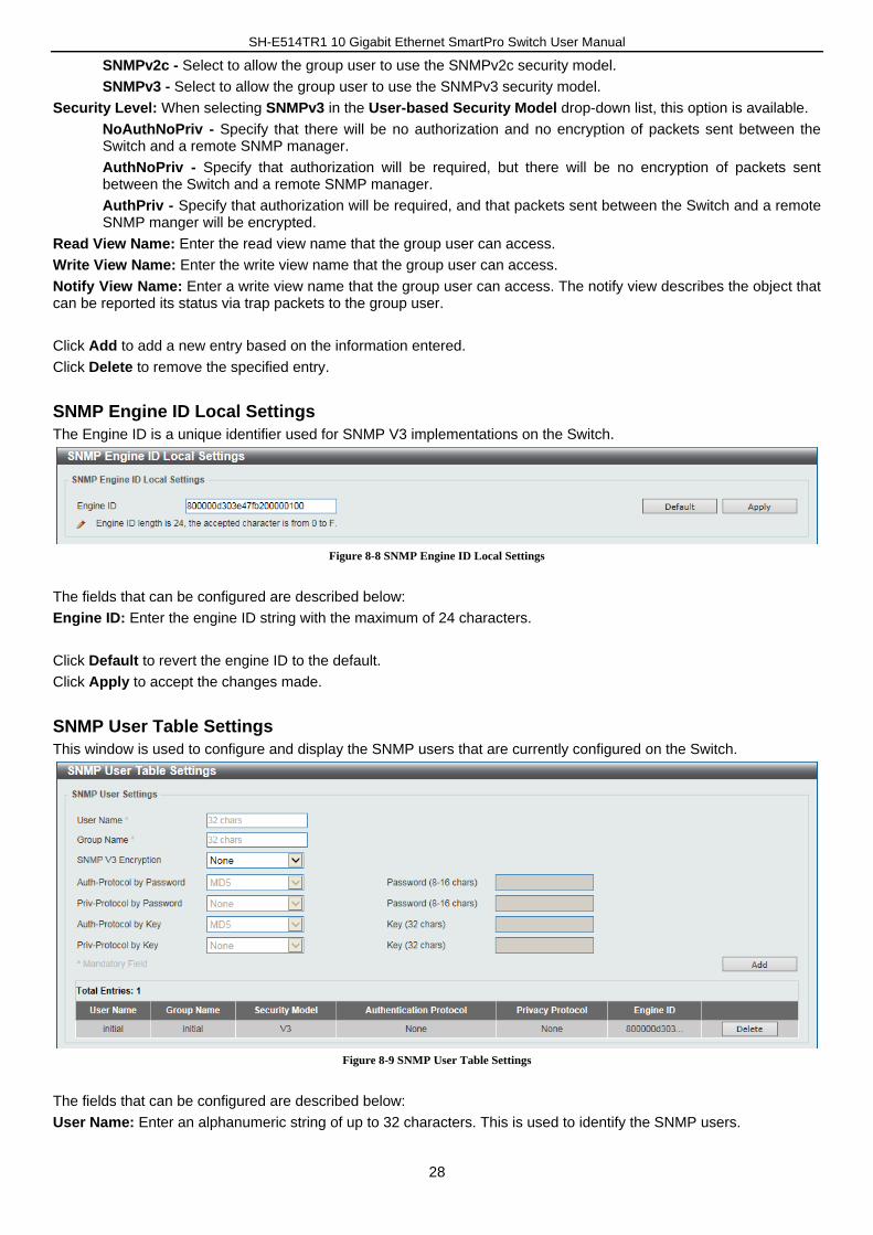
SNMP Group Table Settings
An SNMP Group created with this table maps SNMP users (identified in the SNMP User Table) to the views created in the previous window.
Figure 8-7 SNMP Group Table Settings
The fields that can be configured are described below:
Group Name: Enter the group name of a maximum of 32 characters. The syntax is general string that does not allow space.
User-based Security Model: Select the security model here. Options to choose from are SNMPv1, SNMPv2c, and SNMPv3.
SNMPv1 - Select to allow the group user to use the SNMPv1 security model.
SH-E514TR1 10 Gigabit Ethernet SmartPro Switch User Manual
28
SNMPv2c - Select to allow the group user to use the SNMPv2c security model.
SNMPv3 - Select to allow the group user to use the SNMPv3 security model.
Security Level: When selecting SNMPv3 in the User-based Security Model drop-down list, this option is available.
NoAuthNoPriv - Specify that there will be no authorization and no encryption of packets sent between the Switch and a remote SNMP manager.
AuthNoPriv - Specify that authorization will be required, but there will be no encryption of packets sent between the Switch and a remote SNMP manager.
AuthPriv - Specify that authorization will be required, and that packets sent between the Switch and a remote SNMP manger will be encrypted.
Read View Name: Enter the read view name that the group user can access.
Write View Name: Enter the write view name that the group user can access.
Notify View Name: Enter a write view name that the group user can access. The notify view describes the object that can be reported its status via trap packets to the group user.
Click Add to add a new entry based on the information entered.
Click Delete to remove the specified entry.
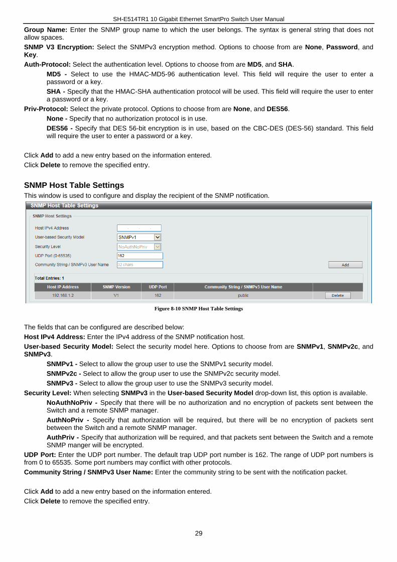
SNMP Engine ID Local Settings
The Engine ID is a unique identifier used for SNMP V3 implementations on the Switch.
Figure 8-8 SNMP Engine ID Local Settings
The fields that can be configured are described below:
Engine ID: Enter the engine ID string with the maximum of 24 characters.
Click Default to revert the engine ID to the default.
Click Apply to accept the changes made.
SNMP User Table Settings
This window is used to configure and display the SNMP users that are currently configured on the Switch.
Figure 8-9 SNMP User Table Settings
The fields that can be configured are described below:
User Name: Enter an alphanumeric string of up to 32 characters. This is used to identify the SNMP users.
SH-E514TR1 10 Gigabit Ethernet SmartPro Switch User Manual
29
Group Name: Enter the SNMP group name to which the user belongs. The syntax is general string that does not allow spaces.
SNMP V3 Encryption: Select the SNMPv3 encryption method. Options to choose from are None, Password, and Key.
Auth-Protocol: Select the authentication level. Options to choose from are MD5, and SHA.
MD5 - Select to use the HMAC-MD5-96 authentication level. This field will require the user to enter a password or a key.
SHA - Specify that the HMAC-SHA authentication protocol will be used. This field will require the user to enter a password or a key.
Priv-Protocol: Select the private protocol. Options to choose from are None, and DES56.
None - Specify that no authorization protocol is in use.
DES56 - Specify that DES 56-bit encryption is in use, based on the CBC-DES (DES-56) standard. This field will require the user to enter a password or a key.
Click Add to add a new entry based on the information entered.
Click Delete to remove the specified entry.
SNMP Host Table Settings
This window is used to configure and display the recipient of the SNMP notification.
Figure 8-10 SNMP Host Table Settings
The fields that can be configured are described below:
Host IPv4 Address: Enter the IPv4 address of the SNMP notification host.
User-based Security Model: Select the security model here. Options to choose from are SNMPv1, SNMPv2c, and SNMPv3.
SNMPv1 - Select to allow the group user to use the SNMPv1 security model.
SNMPv2c - Select to allow the group user to use the SNMPv2c security model.
SNMPv3 - Select to allow the group user to use the SNMPv3 security model.
Security Level: When selecting SNMPv3 in the User-based Security Model drop-down list, this option is available.
NoAuthNoPriv - Specify that there will be no authorization and no encryption of packets sent between the Switch and a remote SNMP manager.
AuthNoPriv - Specify that authorization will be required, but there will be no encryption of packets sent between the Switch and a remote SNMP manager.
AuthPriv - Specify that authorization will be required, and that packets sent between the Switch and a remote SNMP manger will be encrypted.
UDP Port: Enter the UDP port number. The default trap UDP port number is 162. The range of UDP port numbers is from 0 to 65535. Some port numbers may conflict with other protocols.
Community String / SNMPv3 User Name: Enter the community string to be sent with the notification packet.
Click Add to add a new entry based on the information entered.
Click Delete to remove the specified entry.
SH-E514TR1 10 Gigabit Ethernet SmartPro Switch User Manual
30
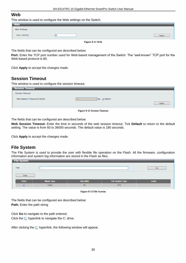
Web This window is used to configure the Web settings on the Switch.
Figure 8-11 Web
The fields that can be configured are described below:
Port: Enter the TCP port number used for Web-based management of the Switch. The “well-known” TCP port for the Web-based protocol is 80.
Click Apply to accept the changes made.
Session Timeout This window is used to configure the session timeout.
Figure 8-12 Session Timeout
The fields that can be configured are described below:
Web Session Timeout: Enter the time in seconds of the web session timeout. Tick Default to return to the default setting. The value is from 60 to 36000 seconds. The default value is 180 seconds.
Click Apply to accept the changes made.
File System The File System is used to provide the user with flexible file operation on the Flash. All the firmware, configuration information and system log information are stored in the Flash as files.
Figure 8-13 File System
The fields that can be configured are described below:
Path: Enter the path string
Click Go to navigate to the path entered.
Click the C: hyperlink to navigate the C: drive.
After clicking the C: hyperlink, the following window will appear.
SH-E514TR1 10 Gigabit Ethernet SmartPro Switch User Manual
31
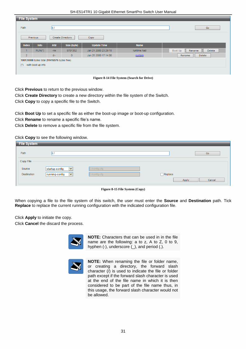
Figure 8-14 File System (Search for Drive)
Click Previous to return to the previous window.
Click Create Directory to create a new directory within the file system of the Switch.
Click Copy to copy a specific file to the Switch.
Click Boot Up to set a specific file as either the boot-up image or boot-up configuration.
Click Rename to rename a specific file’s name.
Click Delete to remove a specific file from the file system.
Click Copy to see the following window.
Figure 8-15 File System (Copy)
When copying a file to the file system of this switch, the user must enter the Source and Destination path. Tick Replace to replace the current running configuration with the indicated configuration file.
Click Apply to initiate the copy.
Click Cancel the discard the process.
NOTE: Characters that can be used in in the file name are the following: a to z, A to Z, 0 to 9, hyphen (-), underscore (_), and period (.).
NOTE: When renaming the file or folder name, or creating a directory, the forward slash character (/) is used to indicate the file or folder path except if the forward slash character is used at the end of the file name in which it is then considered to be part of the file name thus, in this usage, the forward slash character would not be allowed.
SH-E514TR1 10 Gigabit Ethernet SmartPro Switch User Manual
32
9. L2 Features
FDB
Static FDB
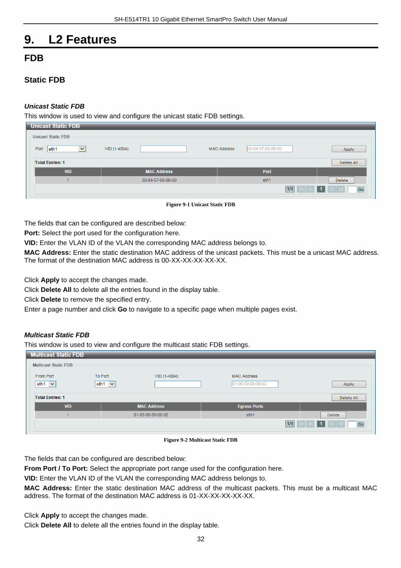
Unicast Static FDB
This window is used to view and configure the unicast static FDB settings.
Figure 9-1 Unicast Static FDB
The fields that can be configured are described below:
Port: Select the port used for the configuration here.
VID: Enter the VLAN ID of the VLAN the corresponding MAC address belongs to.
MAC Address: Enter the static destination MAC address of the unicast packets. This must be a unicast MAC address. The format of the destination MAC address is 00-XX-XX-XX-XX-XX.
Click Apply to accept the changes made.
Click Delete All to delete all the entries found in the display table.
Click Delete to remove the specified entry.
Enter a page number and click Go to navigate to a specific page when multiple pages exist.
Multicast Static FDB
This window is used to view and configure the multicast static FDB settings.
Figure 9-2 Multicast Static FDB
The fields that can be configured are described below:
From Port / To Port: Select the appropriate port range used for the configuration here.
VID: Enter the VLAN ID of the VLAN the corresponding MAC address belongs to.
MAC Address: Enter the static destination MAC address of the multicast packets. This must be a multicast MAC address. The format of the destination MAC address is 01-XX-XX-XX-XX-XX.
Click Apply to accept the changes made.
Click Delete All to delete all the entries found in the display table.
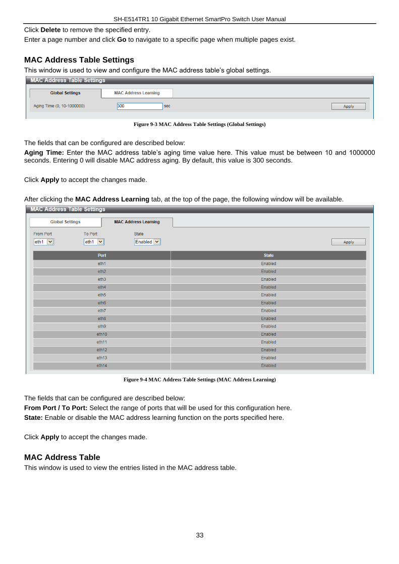
SH-E514TR1 10 Gigabit Ethernet SmartPro Switch User Manual
33
Click Delete to remove the specified entry.
Enter a page number and click Go to navigate to a specific page when multiple pages exist.
MAC Address Table Settings
This window is used to view and configure the MAC address table’s global settings.
Figure 9-3 MAC Address Table Settings (Global Settings)
The fields that can be configured are described below:
Aging Time: Enter the MAC address table’s aging time value here. This value must be between 10 and 1000000 seconds. Entering 0 will disable MAC address aging. By default, this value is 300 seconds.
Click Apply to accept the changes made.
After clicking the MAC Address Learning tab, at the top of the page, the following window will be available.
Figure 9-4 MAC Address Table Settings (MAC Address Learning)
The fields that can be configured are described below:
From Port / To Port: Select the range of ports that will be used for this configuration here.
State: Enable or disable the MAC address learning function on the ports specified here.
Click Apply to accept the changes made.
MAC Address Table
This window is used to view the entries listed in the MAC address table.
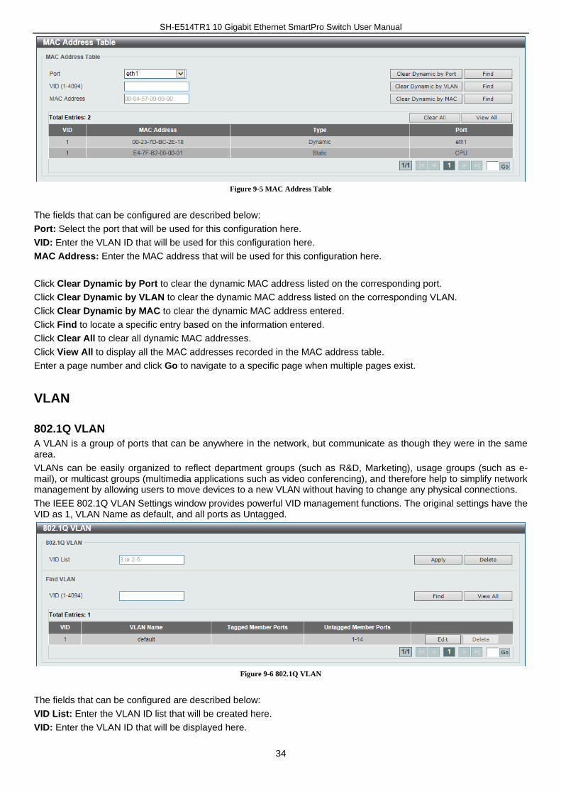
SH-E514TR1 10 Gigabit Ethernet SmartPro Switch User Manual
34
Figure 9-5 MAC Address Table
The fields that can be configured are described below:
Port: Select the port that will be used for this configuration here.
VID: Enter the VLAN ID that will be used for this configuration here.
MAC Address: Enter the MAC address that will be used for this configuration here.
Click Clear Dynamic by Port to clear the dynamic MAC address listed on the corresponding port.
Click Clear Dynamic by VLAN to clear the dynamic MAC address listed on the corresponding VLAN.
Click Clear Dynamic by MAC to clear the dynamic MAC address entered.
Click Find to locate a specific entry based on the information entered.
Click Clear All to clear all dynamic MAC addresses.
Click View All to display all the MAC addresses recorded in the MAC address table.
Enter a page number and click Go to navigate to a specific page when multiple pages exist.
VLAN
802.1Q VLAN
A VLAN is a group of ports that can be anywhere in the network, but communicate as though they were in the same area.
VLANs can be easily organized to reflect department groups (such as R&D, Marketing), usage groups (such as e-mail), or multicast groups (multimedia applications such as video conferencing), and therefore help to simplify network management by allowing users to move devices to a new VLAN without having to change any physical connections.
The IEEE 802.1Q VLAN Settings window provides powerful VID management functions. The original settings have the VID as 1, VLAN Name as default, and all ports as Untagged.
Figure 9-6 802.1Q VLAN
The fields that can be configured are described below:
VID List: Enter the VLAN ID list that will be created here.
VID: Enter the VLAN ID that will be displayed here.
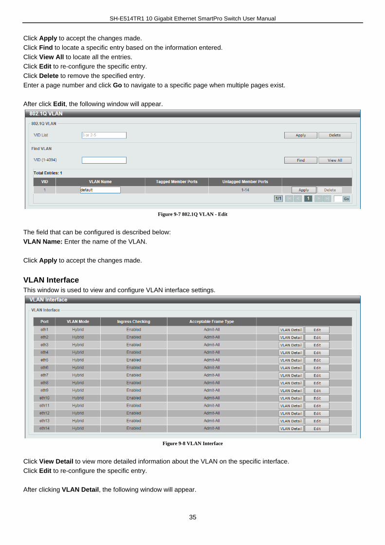
SH-E514TR1 10 Gigabit Ethernet SmartPro Switch User Manual
35
Click Apply to accept the changes made.
Click Find to locate a specific entry based on the information entered.
Click View All to locate all the entries.
Click Edit to re-configure the specific entry.
Click Delete to remove the specified entry.
Enter a page number and click Go to navigate to a specific page when multiple pages exist.
After click Edit, the following window will appear.
Figure 9-7 802.1Q VLAN - Edit
The field that can be configured is described below:
VLAN Name: Enter the name of the VLAN.
Click Apply to accept the changes made.
VLAN Interface
This window is used to view and configure VLAN interface settings.
Figure 9-8 VLAN Interface
Click View Detail to view more detailed information about the VLAN on the specific interface.
Click Edit to re-configure the specific entry.
After clicking VLAN Detail, the following window will appear.
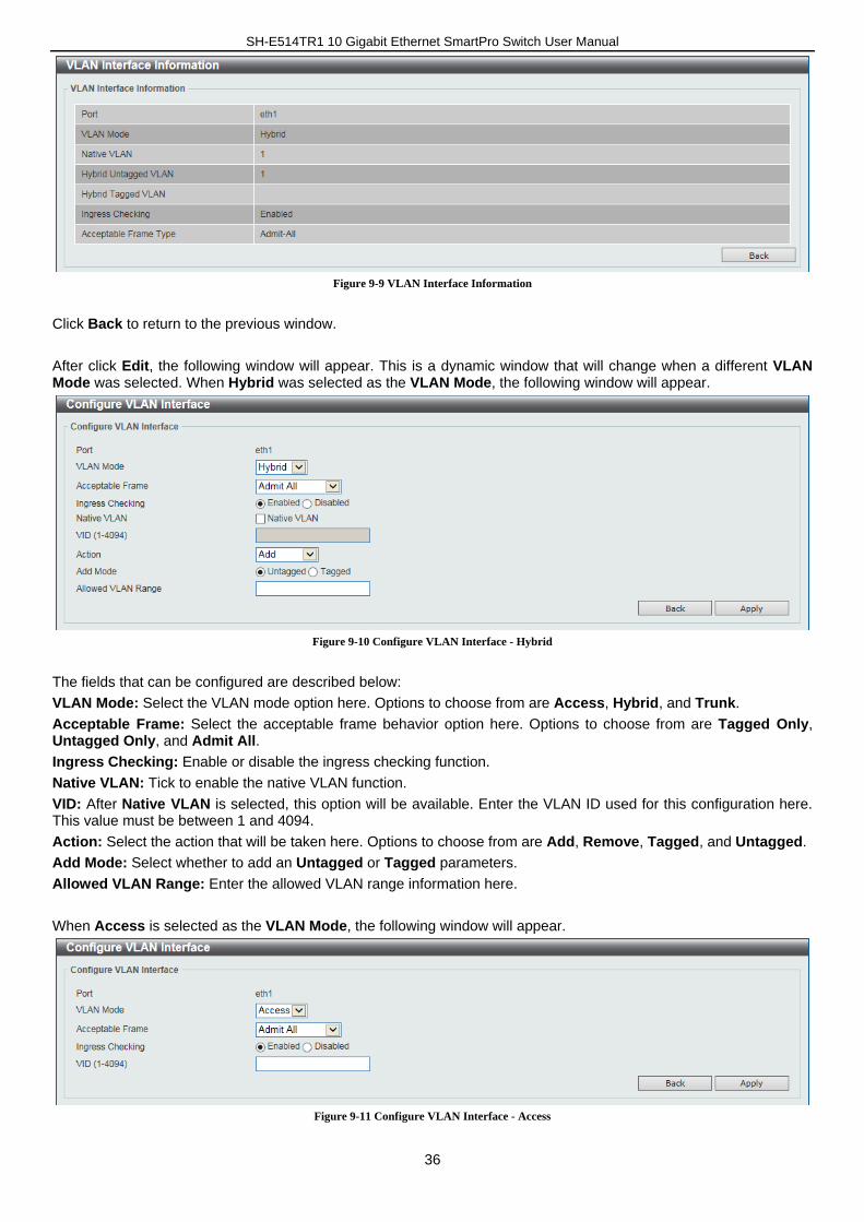
SH-E514TR1 10 Gigabit Ethernet SmartPro Switch User Manual
36
Figure 9-9 VLAN Interface Information
Click Back to return to the previous window.
After click Edit, the following window will appear. This is a dynamic window that will change when a different VLAN Mode was selected. When Hybrid was selected as the VLAN Mode, the following window will appear.
Figure 9-10 Configure VLAN Interface - Hybrid
The fields that can be configured are described below:
VLAN Mode: Select the VLAN mode option here. Options to choose from are Access, Hybrid, and Trunk.
Acceptable Frame: Select the acceptable frame behavior option here. Options to choose from are Tagged Only, Untagged Only, and Admit All.
Ingress Checking: Enable or disable the ingress checking function.
Native VLAN: Tick to enable the native VLAN function.
VID: After Native VLAN is selected, this option will be available. Enter the VLAN ID used for this configuration here. This value must be between 1 and 4094.
Action: Select the action that will be taken here. Options to choose from are Add, Remove, Tagged, and Untagged.
Add Mode: Select whether to add an Untagged or Tagged parameters.
Allowed VLAN Range: Enter the allowed VLAN range information here.
When Access is selected as the VLAN Mode, the following window will appear.
Figure 9-11 Configure VLAN Interface - Access
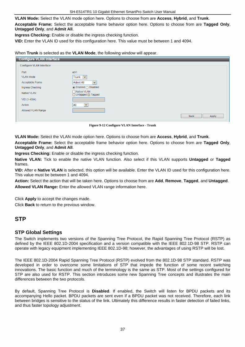
SH-E514TR1 10 Gigabit Ethernet SmartPro Switch User Manual
37
VLAN Mode: Select the VLAN mode option here. Options to choose from are Access, Hybrid, and Trunk.
Acceptable Frame: Select the acceptable frame behavior option here. Options to choose from are Tagged Only, Untagged Only, and Admit All.
Ingress Checking: Enable or disable the ingress checking function.
VID: Enter the VLAN ID used for this configuration here. This value must be between 1 and 4094.
When Trunk is selected as the VLAN Mode, the following window will appear.
Figure 9-12 Configure VLAN Interface - Trunk
VLAN Mode: Select the VLAN mode option here. Options to choose from are Access, Hybrid, and Trunk.
Acceptable Frame: Select the acceptable frame behavior option here. Options to choose from are Tagged Only, Untagged Only, and Admit All.
Ingress Checking: Enable or disable the ingress checking function.
Native VLAN: Tick to enable the native VLAN function. Also select if this VLAN supports Untagged or Tagged frames.
VID: After e Native VLAN is selected, this option will be available. Enter the VLAN ID used for this configuration here. This value must be between 1 and 4094.
Action: Select the action that will be taken here. Options to choose from are Add, Remove, Tagged, and Untagged.
Allowed VLAN Range: Enter the allowed VLAN range information here.
Click Apply to accept the changes made.
Click Back to return to the previous window.
STP
STP Global Settings
The Switch implements two versions of the Spanning Tree Protocol, the Rapid Spanning Tree Protocol (RSTP) as defined by the IEEE 802.1D-2004 specification and a version compatible with the IEEE 802.1D-98 STP. RSTP can operate with legacy equipment implementing IEEE 802.1D-98; however, the advantages of using RSTP will be lost.
The IEEE 802.1D-2004 Rapid Spanning Tree Protocol (RSTP) evolved from the 802.1D-98 STP standard. RSTP was developed in order to overcome some limitations of STP that impede the function of some recent switching innovations. The basic function and much of the terminology is the same as STP. Most of the settings configured for STP are also used for RSTP. This section introduces some new Spanning Tree concepts and illustrates the main differences between the two protocols.
By default, Spanning Tree Protocol is Disabled. If enabled, the Switch will listen for BPDU packets and its accompanying Hello packet. BPDU packets are sent even if a BPDU packet was not received. Therefore, each link between bridges is sensitive to the status of the link. Ultimately this difference results in faster detection of failed links, and thus faster topology adjustment.
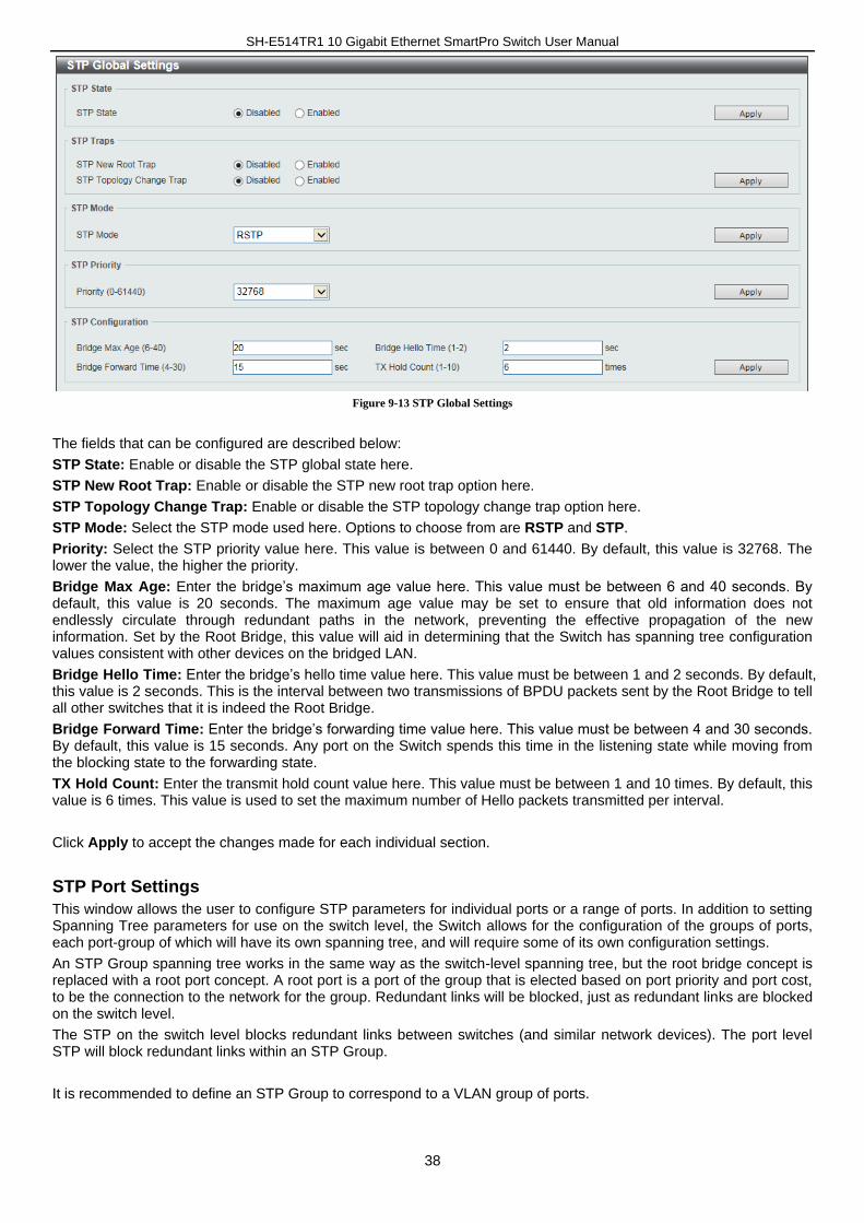
SH-E514TR1 10 Gigabit Ethernet SmartPro Switch User Manual
38
Figure 9-13 STP Global Settings
The fields that can be configured are described below:
STP State: Enable or disable the STP global state here.
STP New Root Trap: Enable or disable the STP new root trap option here.
STP Topology Change Trap: Enable or disable the STP topology change trap option here.
STP Mode: Select the STP mode used here. Options to choose from are RSTP and STP.
Priority: Select the STP priority value here. This value is between 0 and 61440. By default, this value is 32768. The lower the value, the higher the priority.
Bridge Max Age: Enter the bridge’s maximum age value here. This value must be between 6 and 40 seconds. By default, this value is 20 seconds. The maximum age value may be set to ensure that old information does not endlessly circulate through redundant paths in the network, preventing the effective propagation of the new information. Set by the Root Bridge, this value will aid in determining that the Switch has spanning tree configuration values consistent with other devices on the bridged LAN.
Bridge Hello Time: Enter the bridge’s hello time value here. This value must be between 1 and 2 seconds. By default, this value is 2 seconds. This is the interval between two transmissions of BPDU packets sent by the Root Bridge to tell all other switches that it is indeed the Root Bridge.
Bridge Forward Time: Enter the bridge’s forwarding time value here. This value must be between 4 and 30 seconds. By default, this value is 15 seconds. Any port on the Switch spends this time in the listening state while moving from the blocking state to the forwarding state.
TX Hold Count: Enter the transmit hold count value here. This value must be between 1 and 10 times. By default, this value is 6 times. This value is used to set the maximum number of Hello packets transmitted per interval.
Click Apply to accept the changes made for each individual section.
STP Port Settings
This window allows the user to configure STP parameters for individual ports or a range of ports. In addition to setting Spanning Tree parameters for use on the switch level, the Switch allows for the configuration of the groups of ports, each port-group of which will have its own spanning tree, and will require some of its own configuration settings.
An STP Group spanning tree works in the same way as the switch-level spanning tree, but the root bridge concept is replaced with a root port concept. A root port is a port of the group that is elected based on port priority and port cost, to be the connection to the network for the group. Redundant links will be blocked, just as redundant links are blocked on the switch level.
The STP on the switch level blocks redundant links between switches (and similar network devices). The port level STP will block redundant links within an STP Group.
It is recommended to define an STP Group to correspond to a VLAN group of ports.
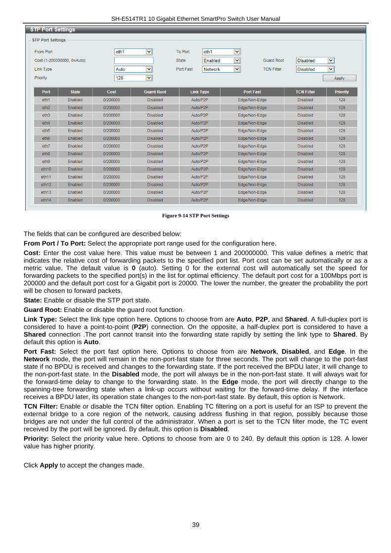
SH-E514TR1 10 Gigabit Ethernet SmartPro Switch User Manual
39
Figure 9-14 STP Port Settings
The fields that can be configured are described below:
From Port / To Port: Select the appropriate port range used for the configuration here.
Cost: Enter the cost value here. This value must be between 1 and 200000000. This value defines a metric that indicates the relative cost of forwarding packets to the specified port list. Port cost can be set automatically or as a metric value. The default value is 0 (auto). Setting 0 for the external cost will automatically set the speed for forwarding packets to the specified port(s) in the list for optimal efficiency. The default port cost for a 100Mbps port is 200000 and the default port cost for a Gigabit port is 20000. The lower the number, the greater the probability the port will be chosen to forward packets.
State: Enable or disable the STP port state.
Guard Root: Enable or disable the guard root function.
Link Type: Select the link type option here. Options to choose from are Auto, P2P, and Shared. A full-duplex port is considered to have a point-to-point (P2P) connection. On the opposite, a half-duplex port is considered to have a Shared connection .The port cannot transit into the forwarding state rapidly by setting the link type to Shared. By default this option is Auto.
Port Fast: Select the port fast option here. Options to choose from are Network, Disabled, and Edge. In the Network mode, the port will remain in the non-port-fast state for three seconds. The port will change to the port-fast state if no BPDU is received and changes to the forwarding state. If the port received the BPDU later, it will change to the non-port-fast state. In the Disabled mode, the port will always be in the non-port-fast state. It will always wait for the forward-time delay to change to the forwarding state. In the Edge mode, the port will directly change to the spanning-tree forwarding state when a link-up occurs without waiting for the forward-time delay. If the interface receives a BPDU later, its operation state changes to the non-port-fast state. By default, this option is Network.
TCN Filter: Enable or disable the TCN filter option. Enabling TC filtering on a port is useful for an ISP to prevent the external bridge to a core region of the network, causing address flushing in that region, possibly because those bridges are not under the full control of the administrator. When a port is set to the TCN filter mode, the TC event received by the port will be ignored. By default, this option is Disabled.
Priority: Select the priority value here. Options to choose from are 0 to 240. By default this option is 128. A lower value has higher priority.
Click Apply to accept the changes made.
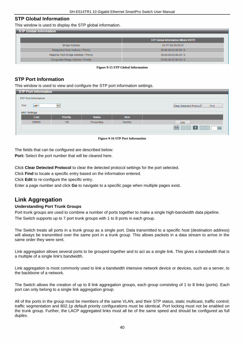
SH-E514TR1 10 Gigabit Ethernet SmartPro Switch User Manual
40
STP Global Information
This window is used to display the STP global information.
Figure 9-15 STP Global Information
STP Port Information
This window is used to view and configure the STP port information settings.
Figure 9-16 STP Port Information
The fields that can be configured are described below:
Port: Select the port number that will be cleared here.
Click Clear Detected Protocol to clear the detected protocol settings for the port selected.
Click Find to locate a specific entry based on the information entered.
Click Edit to re-configure the specific entry.
Enter a page number and click Go to navigate to a specific page when multiple pages exist.
Link Aggregation Understanding Port Trunk Groups
Port trunk groups are used to combine a number of ports together to make a single high-bandwidth data pipeline.
The Switch supports up to 7 port trunk groups with 1 to 8 ports in each group.
The Switch treats all ports in a trunk group as a single port. Data transmitted to a specific host (destination address) will always be transmitted over the same port in a trunk group. This allows packets in a data stream to arrive in the same order they were sent.
Link aggregation allows several ports to be grouped together and to act as a single link. This gives a bandwidth that is a multiple of a single link's bandwidth.
Link aggregation is most commonly used to link a bandwidth intensive network device or devices, such as a server, to the backbone of a network.
The Switch allows the creation of up to 8 link aggregation groups, each group consisting of 1 to 8 links (ports). Each port can only belong to a single link aggregation group.
All of the ports in the group must be members of the same VLAN, and their STP status, static multicast, traffic control; traffic segmentation and 802.1p default priority configurations must be identical. Port locking must not be enabled on the trunk group. Further, the LACP aggregated links must all be of the same speed and should be configured as full duplex.
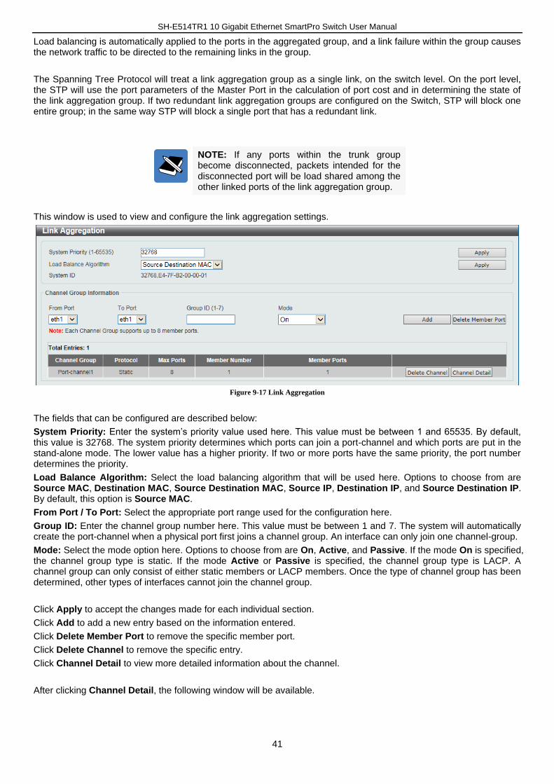
SH-E514TR1 10 Gigabit Ethernet SmartPro Switch User Manual
41
Load balancing is automatically applied to the ports in the aggregated group, and a link failure within the group causes the network traffic to be directed to the remaining links in the group.
The Spanning Tree Protocol will treat a link aggregation group as a single link, on the switch level. On the port level, the STP will use the port parameters of the Master Port in the calculation of port cost and in determining the state of the link aggregation group. If two redundant link aggregation groups are configured on the Switch, STP will block one entire group; in the same way STP will block a single port that has a redundant link.
NOTE: If any ports within the trunk group become disconnected, packets intended for the disconnected port will be load shared among the other linked ports of the link aggregation group.
This window is used to view and configure the link aggregation settings.
Figure 9-17 Link Aggregation
The fields that can be configured are described below:
System Priority: Enter the system’s priority value used here. This value must be between 1 and 65535. By default, this value is 32768. The system priority determines which ports can join a port-channel and which ports are put in the stand-alone mode. The lower value has a higher priority. If two or more ports have the same priority, the port number determines the priority.
Load Balance Algorithm: Select the load balancing algorithm that will be used here. Options to choose from are Source MAC, Destination MAC, Source Destination MAC, Source IP, Destination IP, and Source Destination IP. By default, this option is Source MAC.
From Port / To Port: Select the appropriate port range used for the configuration here.
Group ID: Enter the channel group number here. This value must be between 1 and 7. The system will automatically create the port-channel when a physical port first joins a channel group. An interface can only join one channel-group.
Mode: Select the mode option here. Options to choose from are On, Active, and Passive. If the mode On is specified, the channel group type is static. If the mode Active or Passive is specified, the channel group type is LACP. A channel group can only consist of either static members or LACP members. Once the type of channel group has been determined, other types of interfaces cannot join the channel group.
Click Apply to accept the changes made for each individual section.
Click Add to add a new entry based on the information entered.
Click Delete Member Port to remove the specific member port.
Click Delete Channel to remove the specific entry.
Click Channel Detail to view more detailed information about the channel.
After clicking Channel Detail, the following window will be available.
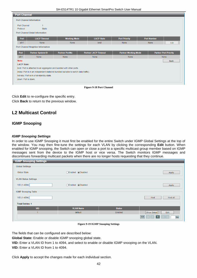
SH-E514TR1 10 Gigabit Ethernet SmartPro Switch User Manual
42
Figure 9-18 Port Channel
Click Edit to re-configure the specific entry.
Click Back to return to the previous window.
L2 Multicast Control
IGMP Snooping
IGMP Snooping Settings
In order to use IGMP Snooping it must first be enabled for the entire Switch under IGMP Global Settings at the top of the window. You may then fine-tune the settings for each VLAN by clicking the corresponding Edit button. When enabled for IGMP snooping, the Switch can open or close a port to a specific multicast group member based on IGMP messages sent from the device to the IGMP host or vice versa. The Switch monitors IGMP messages and discontinues forwarding multicast packets when there are no longer hosts requesting that they continue.
Figure 9-19 IGMP Snooping Settings
The fields that can be configured are described below:
Global State: Enable or disable IGMP snooping global state.
VID: Enter a VLAN ID from 1 to 4094, and select to enable or disable IGMP snooping on the VLAN.
VID: Enter a VLAN ID from 1 to 4094.
Click Apply to accept the changes made for each individual section.
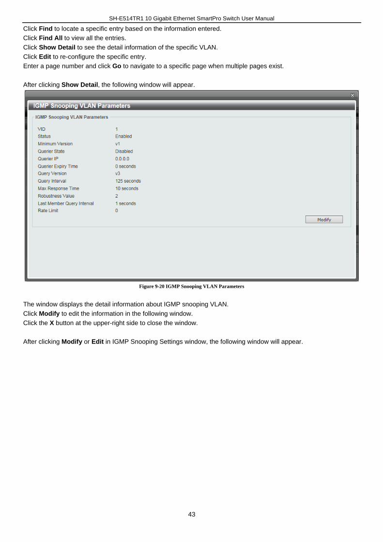
SH-E514TR1 10 Gigabit Ethernet SmartPro Switch User Manual
43
Click Find to locate a specific entry based on the information entered.
Click Find All to view all the entries.
Click Show Detail to see the detail information of the specific VLAN.
Click Edit to re-configure the specific entry.
Enter a page number and click Go to navigate to a specific page when multiple pages exist.
After clicking Show Detail, the following window will appear.
Figure 9-20 IGMP Snooping VLAN Parameters
The window displays the detail information about IGMP snooping VLAN.
Click Modify to edit the information in the following window.
Click the X button at the upper-right side to close the window.
After clicking Modify or Edit in IGMP Snooping Settings window, the following window will appear.
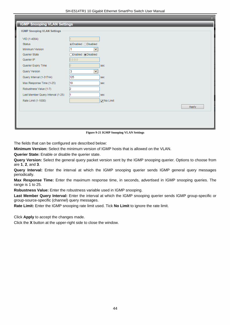
SH-E514TR1 10 Gigabit Ethernet SmartPro Switch User Manual
44
Figure 9-21 IGMP Snooping VLAN Settings
The fields that can be configured are described below:
Minimum Version: Select the minimum version of IGMP hosts that is allowed on the VLAN.
Querier State: Enable or disable the querier state.
Query Version: Select the general query packet version sent by the IGMP snooping querier. Options to choose from are 1, 2, and 3.
Query Interval: Enter the interval at which the IGMP snooping querier sends IGMP general query messages periodically.
Max Response Time: Enter the maximum response time, in seconds, advertised in IGMP snooping queries. The range is 1 to 25.
Robustness Value: Enter the robustness variable used in IGMP snooping.
Last Member Query Interval: Enter the interval at which the IGMP snooping querier sends IGMP group-specific or group-source-specific (channel) query messages.
Rate Limit: Enter the IGMP snooping rate limit used. Tick No Limit to ignore the rate limit.
Click Apply to accept the changes made.
Click the X button at the upper-right side to close the window.
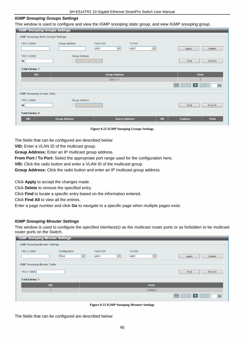
SH-E514TR1 10 Gigabit Ethernet SmartPro Switch User Manual
45
IGMP Snooping Groups Settings
This window is used to configure and view the IGMP snooping static group, and view IGMP snooping group.
Figure 9-22 IGMP Snooping Groups Settings
The fields that can be configured are described below:
VID: Enter a VLAN ID of the multicast group.
Group Address: Enter an IP multicast group address.
From Port / To Port: Select the appropriate port range used for the configuration here.
VID: Click the radio button and enter a VLAN ID of the multicast group.
Group Address: Click the radio button and enter an IP multicast group address.
Click Apply to accept the changes made.
Click Delete to remove the specified entry.
Click Find to locate a specific entry based on the information entered.
Click Find All to view all the entries.
Enter a page number and click Go to navigate to a specific page when multiple pages exist.
IGMP Snooping Mrouter Settings
This window is used to configure the specified interface(s) as the multicast router ports or as forbidden to be multicast router ports on the Switch.
Figure 9-23 IGMP Snooping Mrouter Settings
The fields that can be configured are described below:
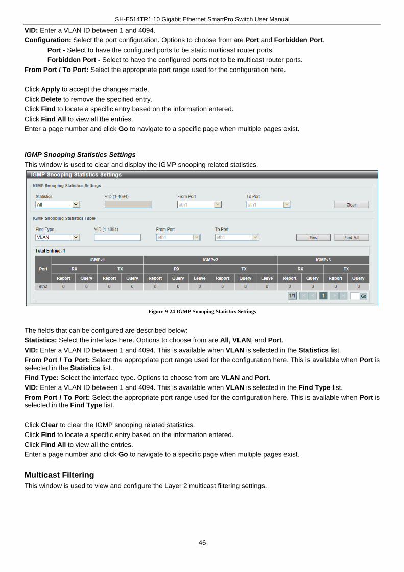
SH-E514TR1 10 Gigabit Ethernet SmartPro Switch User Manual
46
VID: Enter a VLAN ID between 1 and 4094.
Configuration: Select the port configuration. Options to choose from are Port and Forbidden Port.
Port - Select to have the configured ports to be static multicast router ports.
Forbidden Port - Select to have the configured ports not to be multicast router ports.
From Port / To Port: Select the appropriate port range used for the configuration here.
Click Apply to accept the changes made.
Click Delete to remove the specified entry.
Click Find to locate a specific entry based on the information entered.
Click Find All to view all the entries.
Enter a page number and click Go to navigate to a specific page when multiple pages exist.
IGMP Snooping Statistics Settings
This window is used to clear and display the IGMP snooping related statistics.
Figure 9-24 IGMP Snooping Statistics Settings
The fields that can be configured are described below:
Statistics: Select the interface here. Options to choose from are All, VLAN, and Port.
VID: Enter a VLAN ID between 1 and 4094. This is available when VLAN is selected in the Statistics list.
From Port / To Port: Select the appropriate port range used for the configuration here. This is available when Port is selected in the Statistics list.
Find Type: Select the interface type. Options to choose from are VLAN and Port.
VID: Enter a VLAN ID between 1 and 4094. This is available when VLAN is selected in the Find Type list.
From Port / To Port: Select the appropriate port range used for the configuration here. This is available when Port is selected in the Find Type list.
Click Clear to clear the IGMP snooping related statistics.
Click Find to locate a specific entry based on the information entered.
Click Find All to view all the entries.
Enter a page number and click Go to navigate to a specific page when multiple pages exist.
Multicast Filtering
This window is used to view and configure the Layer 2 multicast filtering settings.

SH-E514TR1 10 Gigabit Ethernet SmartPro Switch User Manual
47
Figure 9-25 Multicast Filtering
The fields that can be configured are described below:
VID List: Enter the VLAN ID list that will be used for this configuration here.
Multicast Filter Mode: Select the multicast filter mode here. Options to choose from are Forward Unregistered, Forward All, and Filter Unregistered. When selecting the Forward Unregistered option, registered multicast packets will be forwarded based on the forwarding table and all unregistered multicast packets will be flooded based on the VLAN domain. When selecting the Forward All option, all multicast packets will be flooded based on the VLAN domain. When selecting the Filter Unregistered option, registered packets will be forwarded based on the forwarding table and all unregistered multicast packets will be filtered.
Click Apply to accept the changes made.
Enter a page number and click Go to navigate to a specific page when multiple pages exist.
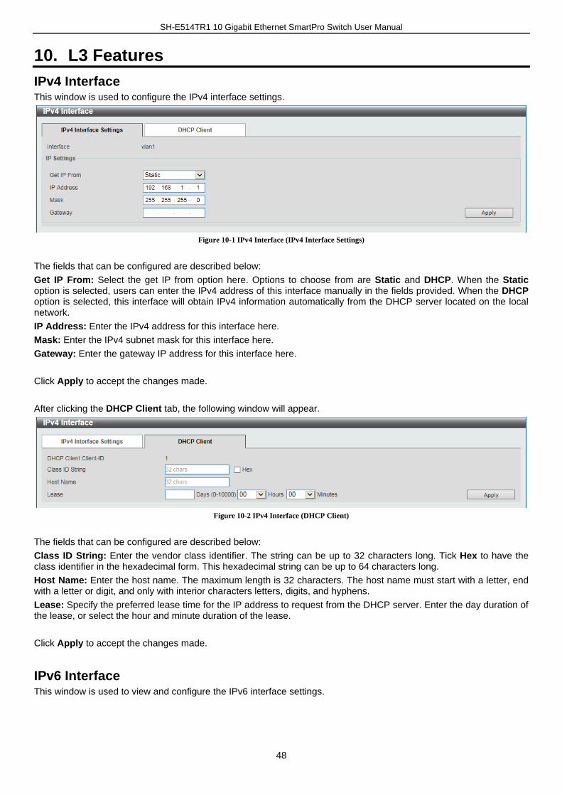
SH-E514TR1 10 Gigabit Ethernet SmartPro Switch User Manual
48
10. L3 Features
IPv4 Interface This window is used to configure the IPv4 interface settings.
Figure 10-1 IPv4 Interface (IPv4 Interface Settings)
The fields that can be configured are described below:
Get IP From: Select the get IP from option here. Options to choose from are Static and DHCP. When the Static option is selected, users can enter the IPv4 address of this interface manually in the fields provided. When the DHCP option is selected, this interface will obtain IPv4 information automatically from the DHCP server located on the local network.
IP Address: Enter the IPv4 address for this interface here.
Mask: Enter the IPv4 subnet mask for this interface here.
Gateway: Enter the gateway IP address for this interface here.
Click Apply to accept the changes made.
After clicking the DHCP Client tab, the following window will appear.
Figure 10-2 IPv4 Interface (DHCP Client)
The fields that can be configured are described below:
Class ID String: Enter the vendor class identifier. The string can be up to 32 characters long. Tick Hex to have the class identifier in the hexadecimal form. This hexadecimal string can be up to 64 characters long.
Host Name: Enter the host name. The maximum length is 32 characters. The host name must start with a letter, end with a letter or digit, and only with interior characters letters, digits, and hyphens.
Lease: Specify the preferred lease time for the IP address to request from the DHCP server. Enter the day duration of the lease, or select the hour and minute duration of the lease.
Click Apply to accept the changes made.
IPv6 Interface This window is used to view and configure the IPv6 interface settings.
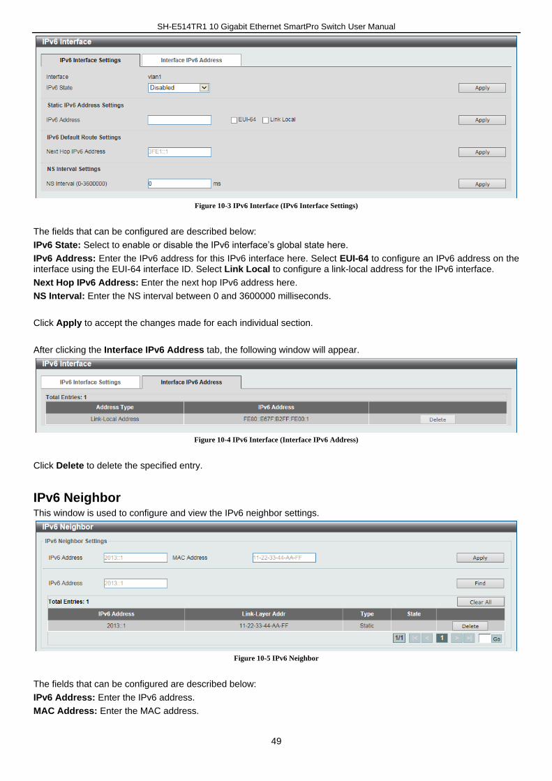
SH-E514TR1 10 Gigabit Ethernet SmartPro Switch User Manual
49
Figure 10-3 IPv6 Interface (IPv6 Interface Settings)
The fields that can be configured are described below:
IPv6 State: Select to enable or disable the IPv6 interface’s global state here.
IPv6 Address: Enter the IPv6 address for this IPv6 interface here. Select EUI-64 to configure an IPv6 address on the interface using the EUI-64 interface ID. Select Link Local to configure a link-local address for the IPv6 interface.
Next Hop IPv6 Address: Enter the next hop IPv6 address here.
NS Interval: Enter the NS interval between 0 and 3600000 milliseconds.
Click Apply to accept the changes made for each individual section.
After clicking the Interface IPv6 Address tab, the following window will appear.
Figure 10-4 IPv6 Interface (Interface IPv6 Address)
Click Delete to delete the specified entry.
IPv6 Neighbor This window is used to configure and view the IPv6 neighbor settings.
Figure 10-5 IPv6 Neighbor
The fields that can be configured are described below:
IPv6 Address: Enter the IPv6 address.
MAC Address: Enter the MAC address.

SH-E514TR1 10 Gigabit Ethernet SmartPro Switch User Manual
50
Click Apply to accept the changes made.
Click Find to locate a specific entry based on the information entered.
Click Clear All to clear all the information in this table.
Click Delete to remove the specific entry.
Enter a page number and click Go to navigate to a specific page when multiple pages exist.
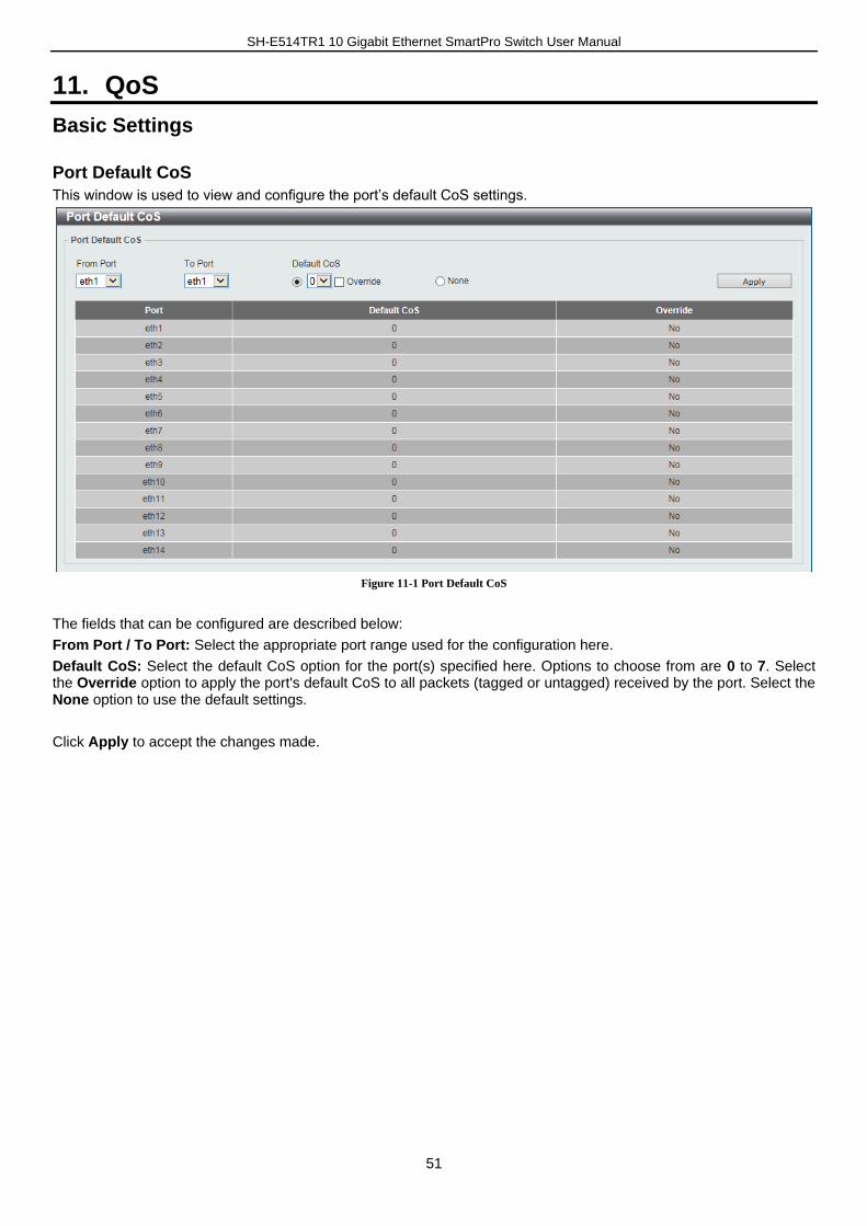
SH-E514TR1 10 Gigabit Ethernet SmartPro Switch User Manual
51
11. QoS
Basic Settings
Port Default CoS
This window is used to view and configure the port’s default CoS settings.
Figure 11-1 Port Default CoS
The fields that can be configured are described below:
From Port / To Port: Select the appropriate port range used for the configuration here.
Default CoS: Select the default CoS option for the port(s) specified here. Options to choose from are 0 to 7. Select the Override option to apply the port's default CoS to all packets (tagged or untagged) received by the port. Select the None option to use the default settings.
Click Apply to accept the changes made.
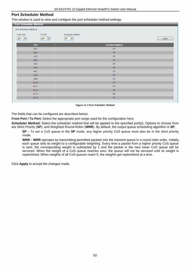
SH-E514TR1 10 Gigabit Ethernet SmartPro Switch User Manual
52
Port Scheduler Method
This window is used to view and configure the port scheduler method settings.
Figure 11-2 Port Scheduler Method
The fields that can be configured are described below:
From Port / To Port: Select the appropriate port range used for the configuration here.
Scheduler Method: Select the scheduler method that will be applied to the specified port(s). Options to choose from are Strict Priority (SP), and Weighted Round-Robin (WRR). By default, the output queue scheduling algorithm is SP.
SP - To set a CoS queue in the SP mode, any higher priority CoS queue must also be in the strict priority mode.
WRR - WRR operates by transmitting permitted packets into the transmit queue in a round robin order. Initially, each queue sets its weight to a configurable weighting. Every time a packet from a higher priority CoS queue is sent, the corresponding weight is subtracted by 1 and the packet in the next lower CoS queue will be serviced. When the weight of a CoS queue reaches zero, the queue will not be serviced until its weight is replenished. When weights of all CoS queues reach 0, the weights get replenished at a time.
Click Apply to accept the changes made.
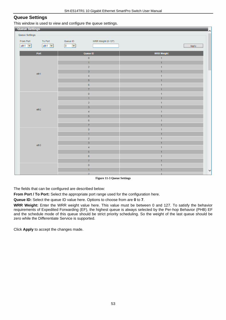
SH-E514TR1 10 Gigabit Ethernet SmartPro Switch User Manual
53
Queue Settings
This window is used to view and configure the queue settings.
Figure 11-3 Queue Settings
The fields that can be configured are described below:
From Port / To Port: Select the appropriate port range used for the configuration here.
Queue ID: Select the queue ID value here. Options to choose from are 0 to 7.
WRR Weight: Enter the WRR weight value here. This value must be between 0 and 127. To satisfy the behavior requirements of Expedited Forwarding (EF), the highest queue is always selected by the Per-hop Behavior (PHB) EF and the schedule mode of this queue should be strict priority scheduling. So the weight of the last queue should be zero while the Differentiate Service is supported.
Click Apply to accept the changes made.
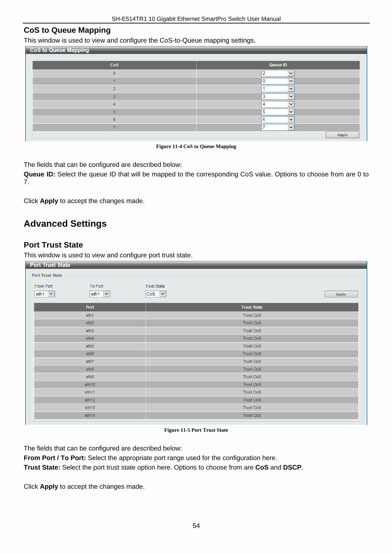
SH-E514TR1 10 Gigabit Ethernet SmartPro Switch User Manual
54
CoS to Queue Mapping
This window is used to view and configure the CoS-to-Queue mapping settings.
Figure 11-4 CoS to Queue Mapping
The fields that can be configured are described below:
Queue ID: Select the queue ID that will be mapped to the corresponding CoS value. Options to choose from are 0 to 7.
Click Apply to accept the changes made.
Advanced Settings
Port Trust State
This window is used to view and configure port trust state.
Figure 11-5 Port Trust State
The fields that can be configured are described below:
From Port / To Port: Select the appropriate port range used for the configuration here.
Trust State: Select the port trust state option here. Options to choose from are CoS and DSCP.
Click Apply to accept the changes made.
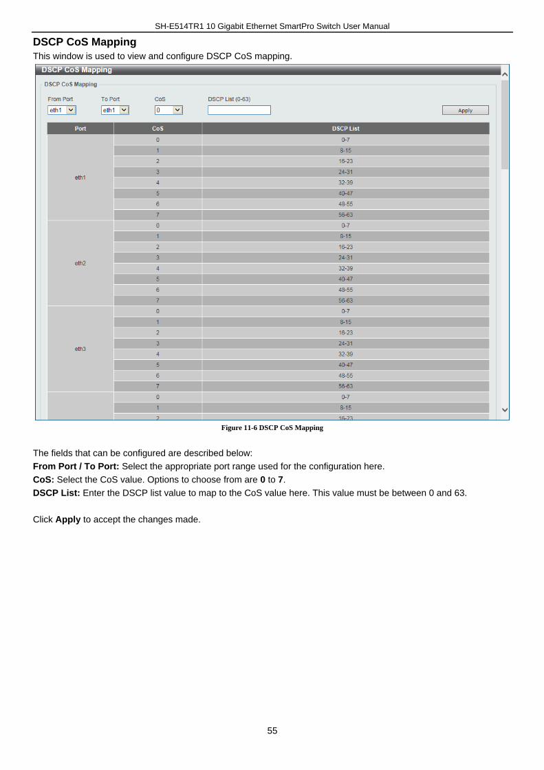
SH-E514TR1 10 Gigabit Ethernet SmartPro Switch User Manual
55
DSCP CoS Mapping
This window is used to view and configure DSCP CoS mapping.
Figure 11-6 DSCP CoS Mapping
The fields that can be configured are described below:
From Port / To Port: Select the appropriate port range used for the configuration here.
CoS: Select the CoS value. Options to choose from are 0 to 7.
DSCP List: Enter the DSCP list value to map to the CoS value here. This value must be between 0 and 63.
Click Apply to accept the changes made.
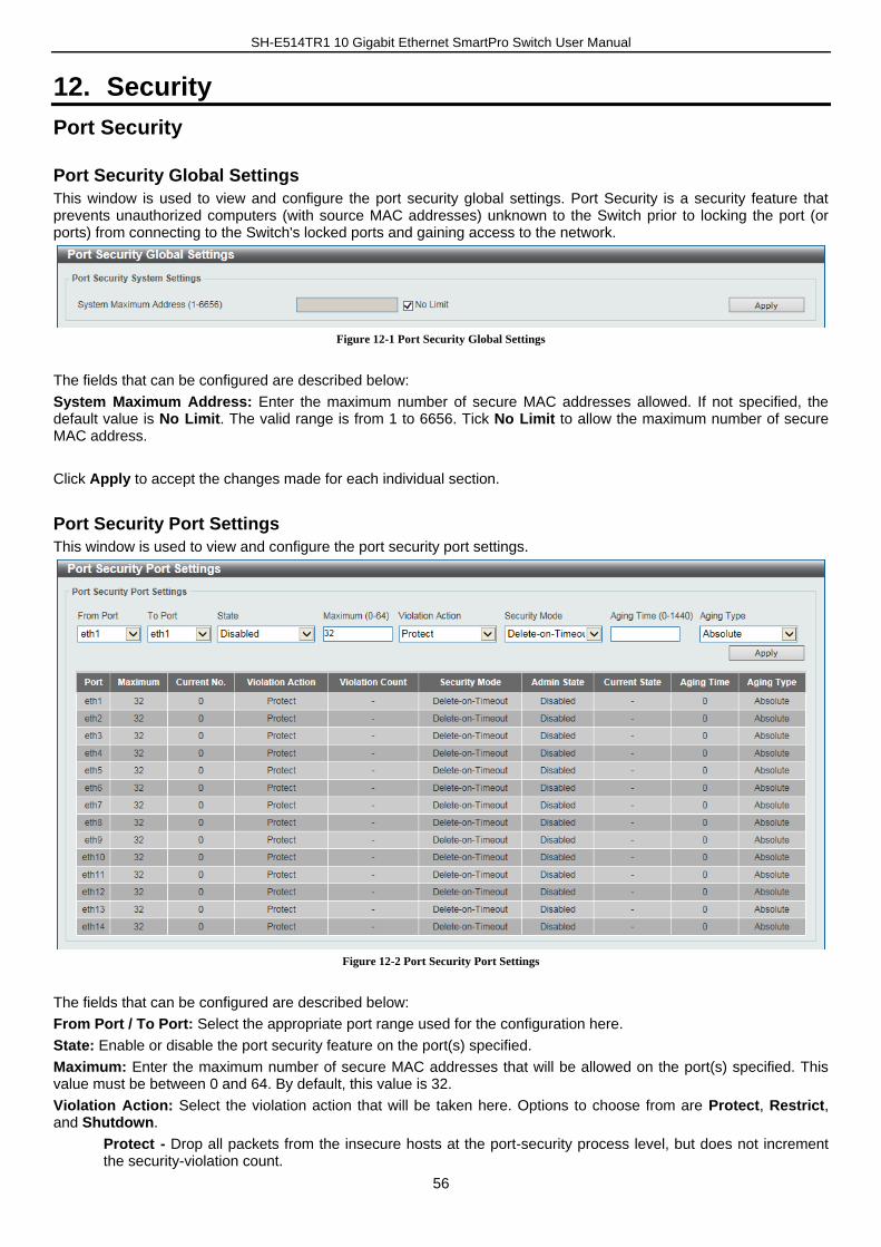
SH-E514TR1 10 Gigabit Ethernet SmartPro Switch User Manual
56
12. Security
Port Security
Port Security Global Settings
This window is used to view and configure the port security global settings. Port Security is a security feature that prevents unauthorized computers (with source MAC addresses) unknown to the Switch prior to locking the port (or ports) from connecting to the Switch's locked ports and gaining access to the network.
Figure 12-1 Port Security Global Settings
The fields that can be configured are described below:
System Maximum Address: Enter the maximum number of secure MAC addresses allowed. If not specified, the default value is No Limit. The valid range is from 1 to 6656. Tick No Limit to allow the maximum number of secure MAC address.
Click Apply to accept the changes made for each individual section.
Port Security Port Settings
This window is used to view and configure the port security port settings.
Figure 12-2 Port Security Port Settings
The fields that can be configured are described below:
From Port / To Port: Select the appropriate port range used for the configuration here.
State: Enable or disable the port security feature on the port(s) specified.
Maximum: Enter the maximum number of secure MAC addresses that will be allowed on the port(s) specified. This value must be between 0 and 64. By default, this value is 32.
Violation Action: Select the violation action that will be taken here. Options to choose from are Protect, Restrict, and Shutdown.
Protect - Drop all packets from the insecure hosts at the port-security process level, but does not increment the security-violation count.
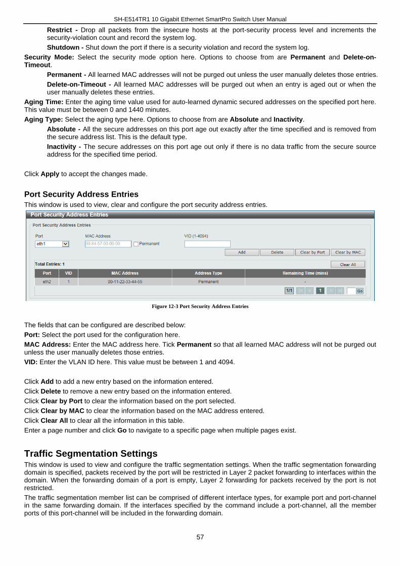
SH-E514TR1 10 Gigabit Ethernet SmartPro Switch User Manual
57
Restrict - Drop all packets from the insecure hosts at the port-security process level and increments the security-violation count and record the system log.
Shutdown - Shut down the port if there is a security violation and record the system log.
Security Mode: Select the security mode option here. Options to choose from are Permanent and Delete-on-Timeout.
Permanent - All learned MAC addresses will not be purged out unless the user manually deletes those entries.
Delete-on-Timeout - All learned MAC addresses will be purged out when an entry is aged out or when the user manually deletes these entries.
Aging Time: Enter the aging time value used for auto-learned dynamic secured addresses on the specified port here. This value must be between 0 and 1440 minutes.
Aging Type: Select the aging type here. Options to choose from are Absolute and Inactivity.
Absolute - All the secure addresses on this port age out exactly after the time specified and is removed from the secure address list. This is the default type.
Inactivity - The secure addresses on this port age out only if there is no data traffic from the secure source address for the specified time period.
Click Apply to accept the changes made.
Port Security Address Entries
This window is used to view, clear and configure the port security address entries.
Figure 12-3 Port Security Address Entries
The fields that can be configured are described below:
Port: Select the port used for the configuration here.
MAC Address: Enter the MAC address here. Tick Permanent so that all learned MAC address will not be purged out unless the user manually deletes those entries.
VID: Enter the VLAN ID here. This value must be between 1 and 4094.
Click Add to add a new entry based on the information entered.
Click Delete to remove a new entry based on the information entered.
Click Clear by Port to clear the information based on the port selected.
Click Clear by MAC to clear the information based on the MAC address entered.
Click Clear All to clear all the information in this table.
Enter a page number and click Go to navigate to a specific page when multiple pages exist.
Traffic Segmentation Settings This window is used to view and configure the traffic segmentation settings. When the traffic segmentation forwarding domain is specified, packets received by the port will be restricted in Layer 2 packet forwarding to interfaces within the domain. When the forwarding domain of a port is empty, Layer 2 forwarding for packets received by the port is not restricted.
The traffic segmentation member list can be comprised of different interface types, for example port and port-channel in the same forwarding domain. If the interfaces specified by the command include a port-channel, all the member ports of this port-channel will be included in the forwarding domain.
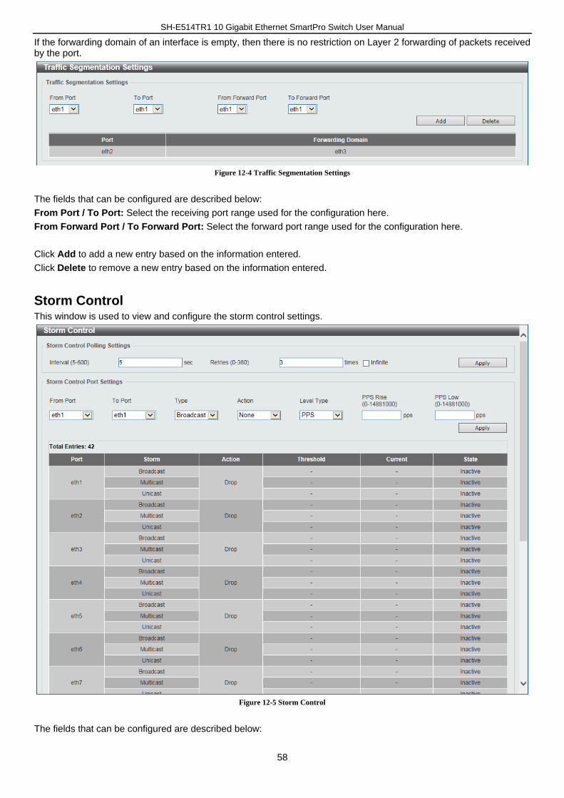
SH-E514TR1 10 Gigabit Ethernet SmartPro Switch User Manual
58
If the forwarding domain of an interface is empty, then there is no restriction on Layer 2 forwarding of packets received by the port.
Figure 12-4 Traffic Segmentation Settings
The fields that can be configured are described below:
From Port / To Port: Select the receiving port range used for the configuration here.
From Forward Port / To Forward Port: Select the forward port range used for the configuration here.
Click Add to add a new entry based on the information entered.
Click Delete to remove a new entry based on the information entered.
Storm Control This window is used to view and configure the storm control settings.
Figure 12-5 Storm Control
The fields that can be configured are described below:
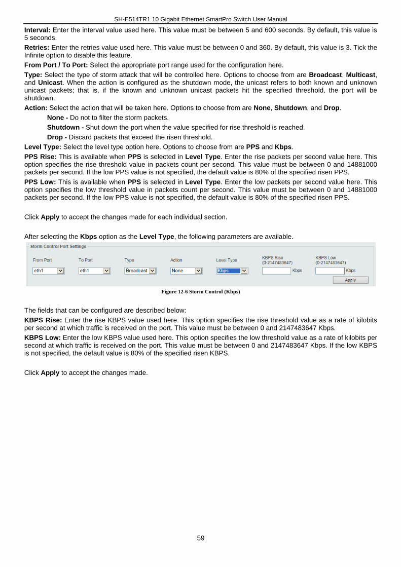
SH-E514TR1 10 Gigabit Ethernet SmartPro Switch User Manual
59
Interval: Enter the interval value used here. This value must be between 5 and 600 seconds. By default, this value is 5 seconds.
Retries: Enter the retries value used here. This value must be between 0 and 360. By default, this value is 3. Tick the Infinite option to disable this feature.
From Port / To Port: Select the appropriate port range used for the configuration here.
Type: Select the type of storm attack that will be controlled here. Options to choose from are Broadcast, Multicast, and Unicast. When the action is configured as the shutdown mode, the unicast refers to both known and unknown unicast packets; that is, if the known and unknown unicast packets hit the specified threshold, the port will be shutdown.
Action: Select the action that will be taken here. Options to choose from are None, Shutdown, and Drop.
None - Do not to filter the storm packets.
Shutdown - Shut down the port when the value specified for rise threshold is reached.
Drop - Discard packets that exceed the risen threshold.
Level Type: Select the level type option here. Options to choose from are PPS and Kbps.
PPS Rise: This is available when PPS is selected in Level Type. Enter the rise packets per second value here. This option specifies the rise threshold value in packets count per second. This value must be between 0 and 14881000 packets per second. If the low PPS value is not specified, the default value is 80% of the specified risen PPS.
PPS Low: This is available when PPS is selected in Level Type. Enter the low packets per second value here. This option specifies the low threshold value in packets count per second. This value must be between 0 and 14881000 packets per second. If the low PPS value is not specified, the default value is 80% of the specified risen PPS.
Click Apply to accept the changes made for each individual section.
After selecting the Kbps option as the Level Type, the following parameters are available.
Figure 12-6 Storm Control (Kbps)
The fields that can be configured are described below:
KBPS Rise: Enter the rise KBPS value used here. This option specifies the rise threshold value as a rate of kilobits per second at which traffic is received on the port. This value must be between 0 and 2147483647 Kbps.
KBPS Low: Enter the low KBPS value used here. This option specifies the low threshold value as a rate of kilobits per second at which traffic is received on the port. This value must be between 0 and 2147483647 Kbps. If the low KBPS is not specified, the default value is 80% of the specified risen KBPS.
Click Apply to accept the changes made.
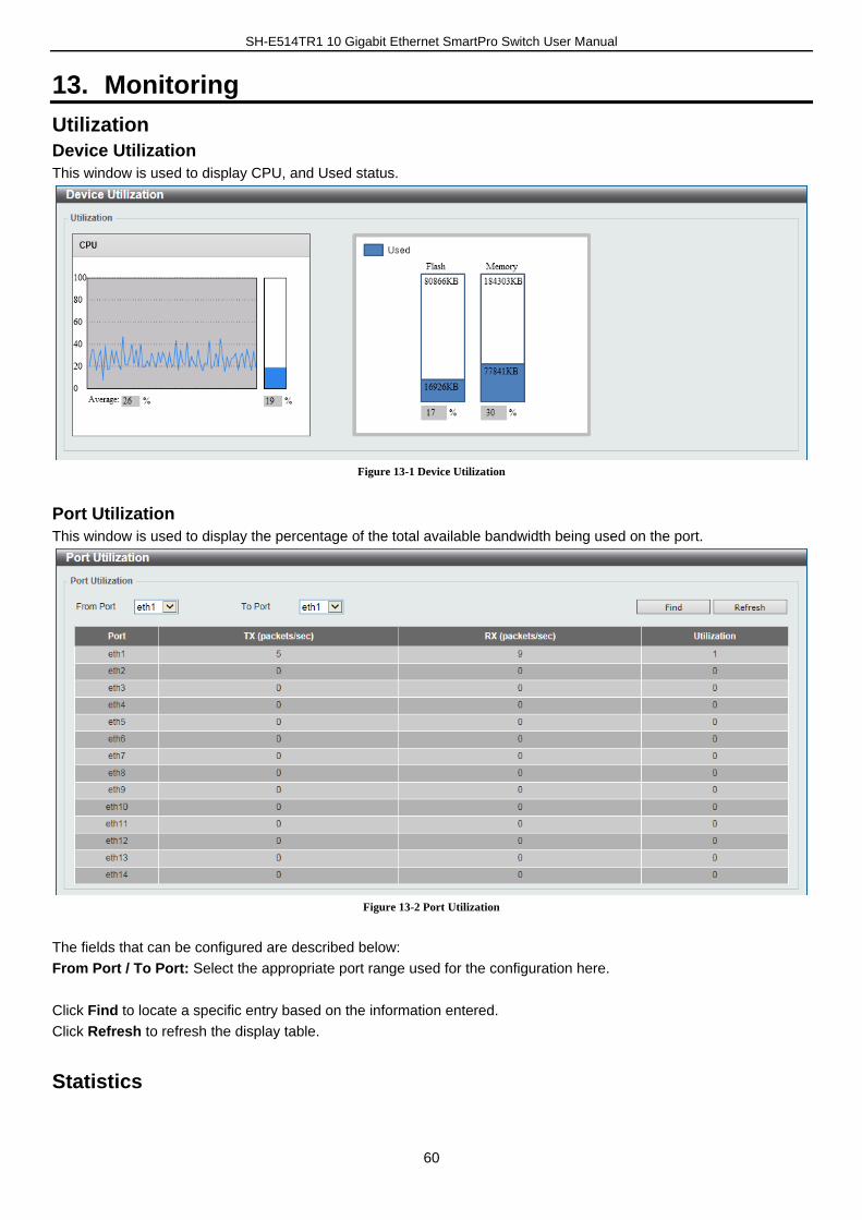
SH-E514TR1 10 Gigabit Ethernet SmartPro Switch User Manual
60
13. Monitoring
Utilization
Device Utilization
This window is used to display CPU, and Used status.
Figure 13-1 Device Utilization
Port Utilization
This window is used to display the percentage of the total available bandwidth being used on the port.
Figure 13-2 Port Utilization
The fields that can be configured are described below:
From Port / To Port: Select the appropriate port range used for the configuration here.
Click Find to locate a specific entry based on the information entered.
Click Refresh to refresh the display table.
Statistics
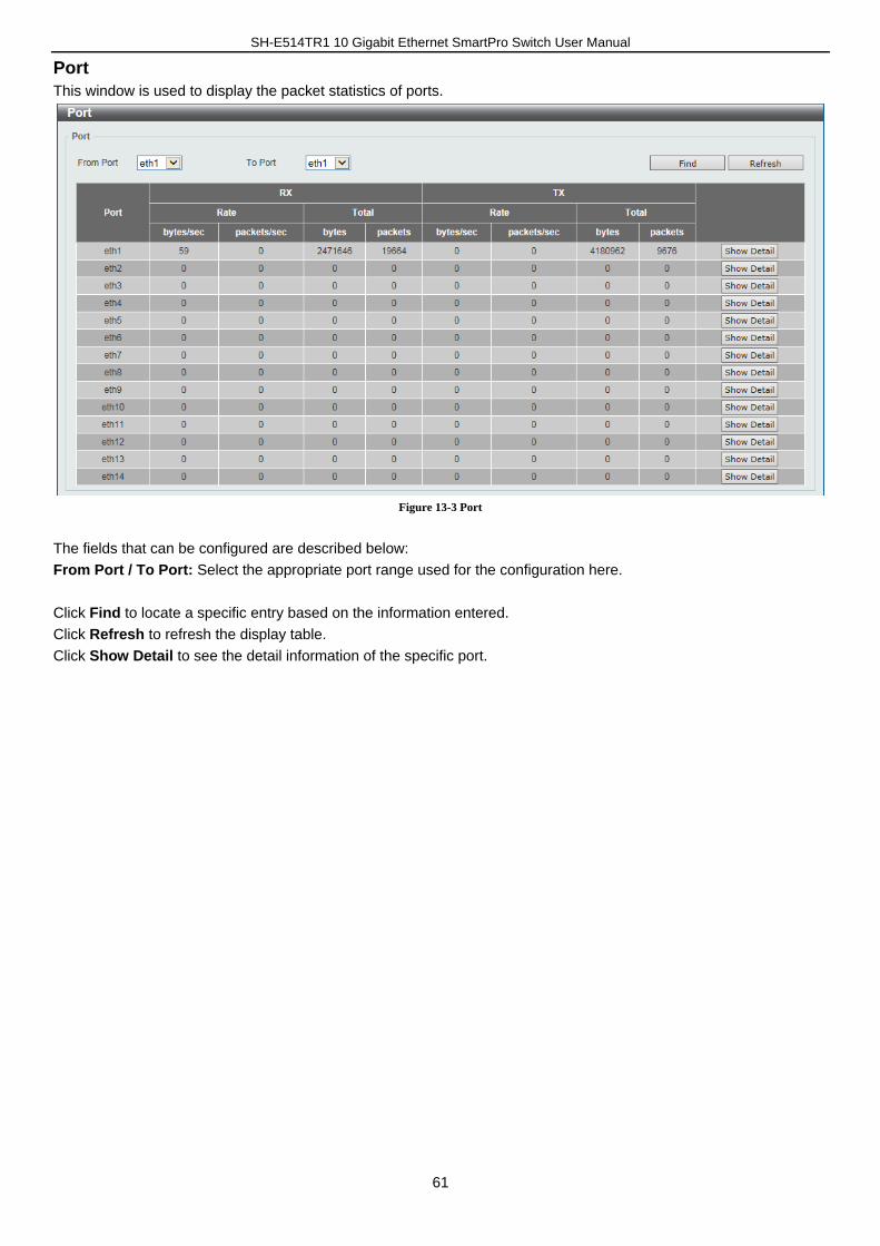
SH-E514TR1 10 Gigabit Ethernet SmartPro Switch User Manual
61
Port
This window is used to display the packet statistics of ports.
Figure 13-3 Port
The fields that can be configured are described below:
From Port / To Port: Select the appropriate port range used for the configuration here.
Click Find to locate a specific entry based on the information entered.
Click Refresh to refresh the display table.
Click Show Detail to see the detail information of the specific port.
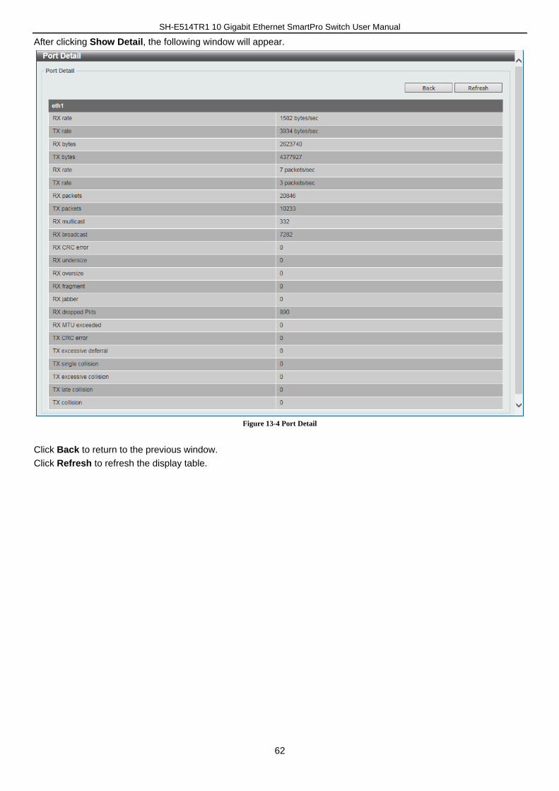
SH-E514TR1 10 Gigabit Ethernet SmartPro Switch User Manual
62
After clicking Show Detail, the following window will appear.
Figure 13-4 Port Detail
Click Back to return to the previous window.
Click Refresh to refresh the display table.
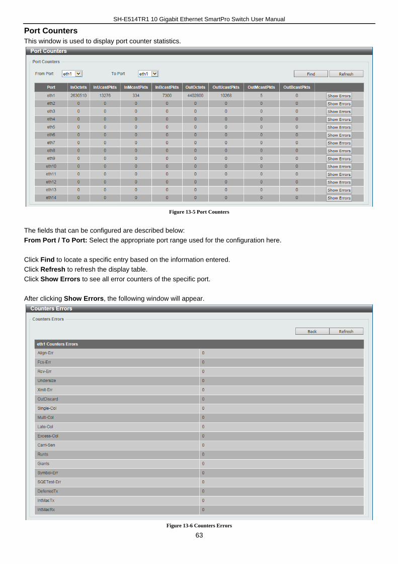
SH-E514TR1 10 Gigabit Ethernet SmartPro Switch User Manual
63
Port Counters
This window is used to display port counter statistics.
Figure 13-5 Port Counters
The fields that can be configured are described below:
From Port / To Port: Select the appropriate port range used for the configuration here.
Click Find to locate a specific entry based on the information entered.
Click Refresh to refresh the display table.
Click Show Errors to see all error counters of the specific port.
After clicking Show Errors, the following window will appear.
Figure 13-6 Counters Errors
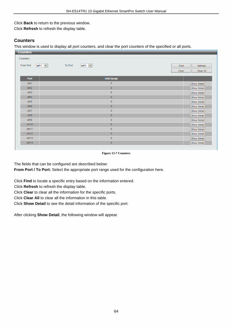
SH-E514TR1 10 Gigabit Ethernet SmartPro Switch User Manual
64
Click Back to return to the previous window.
Click Refresh to refresh the display table.
Counters
This window is used to display all port counters, and clear the port counters of the specified or all ports.
Figure 13-7 Counters
The fields that can be configured are described below:
From Port / To Port: Select the appropriate port range used for the configuration here.
Click Find to locate a specific entry based on the information entered.
Click Refresh to refresh the display table.
Click Clear to clear all the information for the specific ports.
Click Clear All to clear all the information in this table.
Click Show Detail to see the detail information of the specific port.
After clicking Show Detail, the following window will appear.
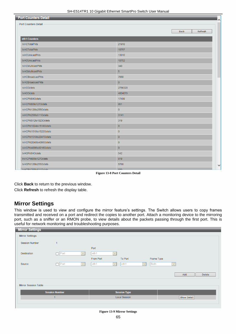
SH-E514TR1 10 Gigabit Ethernet SmartPro Switch User Manual
65
Figure 13-8 Port Counters Detail
Click Back to return to the previous window.
Click Refresh to refresh the display table.
Mirror Settings This window is used to view and configure the mirror feature’s settings. The Switch allows users to copy frames transmitted and received on a port and redirect the copies to another port. Attach a monitoring device to the mirroring port, such as a sniffer or an RMON probe, to view details about the packets passing through the first port. This is useful for network monitoring and troubleshooting purposes.
Figure 13-9 Mirror Settings
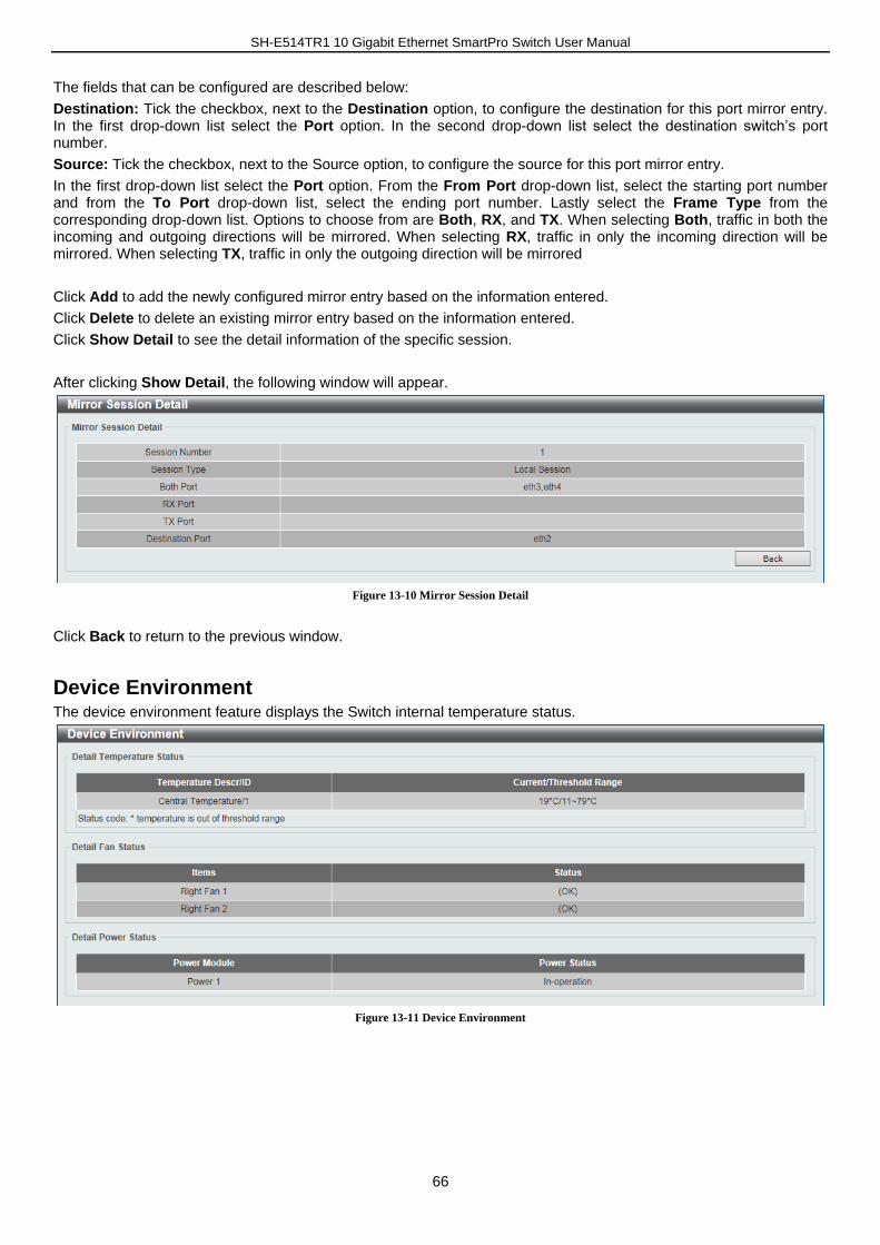
SH-E514TR1 10 Gigabit Ethernet SmartPro Switch User Manual
66
The fields that can be configured are described below:
Destination: Tick the checkbox, next to the Destination option, to configure the destination for this port mirror entry. In the first drop-down list select the Port option. In the second drop-down list select the destination switch’s port number.
Source: Tick the checkbox, next to the Source option, to configure the source for this port mirror entry.
In the first drop-down list select the Port option. From the From Port drop-down list, select the starting port number and from the To Port drop-down list, select the ending port number. Lastly select the Frame Type from the corresponding drop-down list. Options to choose from are Both, RX, and TX. When selecting Both, traffic in both the incoming and outgoing directions will be mirrored. When selecting RX, traffic in only the incoming direction will be mirrored. When selecting TX, traffic in only the outgoing direction will be mirrored
Click Add to add the newly configured mirror entry based on the information entered.
Click Delete to delete an existing mirror entry based on the information entered.
Click Show Detail to see the detail information of the specific session.
After clicking Show Detail, the following window will appear.
Figure 13-10 Mirror Session Detail
Click Back to return to the previous window.
Device Environment The device environment feature displays the Switch internal temperature status.
Figure 13-11 Device Environment