RVXVHT080G IM E 24909 - valinta.lt SAMSUNG/04... · RVXVHT080G_IM_E_24909.indd 2 2007-01-08...
40
ENGLISH INSTALLATION MANUAL RVXVHT080G Series RVXVHT100G Series RVXVHT120G Series RVXVHT140G Series RVXFHT080G Series RVXFHT100G Series RVXFHT120G Series RVXFHT140G Series System Air Conditioner (Cooling and Heating) ESPAÑOL FRANÇAIS ITALIANO DEUTSCH E S F I D DB98-24909A(2)
Transcript of RVXVHT080G IM E 24909 - valinta.lt SAMSUNG/04... · RVXVHT080G_IM_E_24909.indd 2 2007-01-08...

ENG
LISH
INSTALLATION MANUALRVXVHT080G SeriesRVXVHT100G SeriesRVXVHT120G SeriesRVXVHT140G SeriesRVXFHT080G SeriesRVXFHT100G SeriesRVXFHT120G SeriesRVXFHT140G Series
System Air Conditioner (Cooling and Heating)
ESPA
ÑO
LFR
AN
ÇAIS
ITA
LIA
NO
DEU
TSCH
E S F I D DB98-24909A(2)
RVXVHT080G_IM_E_24909.indd 41 2007-01-08 ソタネト 4:04:31

E-2
Contents
PREPARING THE INSTALLATION Locating the Units . . . . . . . . . . . . . . . . . . . . . . . . . . . . . . . . . . . . . . . . . . . . . . 6
INSTALLING THE UNIT Wiring Work . . . . . . . . . . . . . . . . . . . . . . . . . . . . . . . . . . . . . . . . . . . . . . . . . . . 12
Refrigerant Pipe Work . . . . . . . . . . . . . . . . . . . . . . . . . . . . . . . . . . . . . . . . . 20
COMPLETING THE INSTALLATION AND COMMISSIONING Performing the Refrigerant Gas Leak Test . . . . . . . . . . . . . . . . . . . . . 32
Preparing and Charging the Refrigerant Pipe . . . . . . . . . . . . . . . . . 33 Setting the Option Switch and Function of the Keys . . . . . . . . . . 36 Completing the Installation . . . . . . . . . . . . . . . . . . . . . . . . . . . . . . . . . . . 38 Final Checks and Trial Operation . . . . . . . . . . . . . . . . . . . . . . . . . . . . . . . 39
RVXVHT080G_IM_E_24909.indd 2 2007-01-08 ソタネト 4:03:33

E-3
ENG
LISH
Safety PrecautionsThe following safety precautions must be taken when installing the unit.
R410A refrigerant is used for DVM PLUS II air conditioner. - When using R410A, moisture or foreign substances may affect to the capacity and reliability of
the product. Safety precautions must be taken when installing the refrigerant pipe.
- The design pressure of the unit is 4.1MPa. Select appropriate material and thickness according to the regulations.
- R410A is a quasi-azeotrope of two refrigerants. Make sure to charge liquid one when adding refrigerant. If you charge gaseous refrigerant, it may affect the capacity and reliability of the product as a result of change formation of the refrigerant.
Connect only the indoor units fit on R410A refrigerant. Check whether the indoor units can be connected with the product’s catalogue. (When incorrect indoor units are connected, they cannot operate normally.)
RVXVHT080G_IM_E_24909.indd 3 2007-01-08 ソタネト 4:03:33

E-4
WARNING If you don’t follow the safety precautions, you may get the risk of serious wound or death.
The installation must be done by the manufacturer or its service agent or a similar qualified person in order to avoid a hazard. - Installation by an unqualified person may cause a water leakage, electric shock or fire and so on.
The electric work must be done by service agent or similarly qualified persons according to national wiring regulations and use only rated cable. - If the capacity of the power cable is insufficient or electric work is not properly completed, electric
shock or fire may occur. Install the outdoor unit correctly according to the installation manual.
- An incorrect installation may cause a water leakage, electric shock or fire and so on. Manufacturer is not responsible for accidents due to incorrect installation. When you install the air conditioner in a small room, you consider a proper ventilation to prevent a
leakage level within the maximum permissible limit. - In that case, you may die from suffocation by some possibility.
Use only rated parts and tools. - If you don’t use the rated parts and tools, it can cause trouble with the air conditioner and bring
about injury. Install the outdoor unit on a hard and even place that can support its weight.
- If the place cannot support its weight, the outdoor unit may fall down and it may cause injury. Fix the outdoor unit securely to prepare against strong wind or earthquake.
- If the outdoor unit is not properly fixed, it turns over and accidents may occur. Install the cables with supplied cables firmly. Fix them securely so that external force is not exerted to
the terminal board. - If the connection or fixing is incomplete, it can cause trouble with a heat generation, electric shock or
fire and so on. Arrange the cables between the indoor and outdoor unit after connecting. Attach the cover securely
so that the electrical component box cover does not get loosen. - If the cover is attached incompletely, it can cause trouble with a heat generation, electric shock or fire
of the terminal board. Install separate MCCB and ELB when installing the power cable.
- If you do not install the MCCB and ELB, electric shock or fire may occur. The unit must be plugged into an independent circuit if applicable or connect the power cable to the
auxiliary circuit breaker. An all pole disconnection from the power supply must be incorporated in the fixed wiring with a contact opening of >3mm.
If any gas or impurities except R410A refrigerant come into the refrigerant pipe, serious problem may occur and it may cause injury.
Make sure there is no leakage after installation. - Toxic gas may generate when refrigerant gas contacts with fire.
Leak test must be done using only Nitrogen gas.
RVXVHT080G_IM_E_24909.indd 4 2007-01-08 ソタネト 4:03:33

E-5
ENG
LISH
CAUTION If you don’t follow the safety precautions, you may get the risk of injury or loss of property.
Make sure of a earthing. - Do not connect the earth wire to the gas pipe, water pipe, lighting rod or telephone wire.
If earthing is incomplete, electric shock or fire may occur. Do not connect the heater to the outdoor unit and do not install remodeled duct as you please.
- The capacity of the air conditioner may reduce, electric shock or fire may occur and it has a chance of occurrence of and accident like electric shock or fire.
Make sure that the condensed water dripping from the drain hose runs out properly and insulate the drain pipe so that frost does not generate. - Household goods may get wet if the drain pipe is not properly installed.
Install the power cable and communication cable of the indoor and outdoor unit at least 1m away from electric appliances. - Noise may heard depending on the electric wave though the cables are installed away from
electric appliances. Install the indoor unit away from lighting apparatus using the ballast.
- If you use the wireless remote control, it may not operate normally. Do not install the air conditioner in following places.
- The place where there is mineral oil or arsenic acid There is a chance that parts may get damaged due to burned resin. The capacity of the heat exchanger may reduce or the air conditioner may be out of order.
- The place where corrosive gas such as sulfurous acid gas generates from the vent pipe or air outlet The copper pipe or connection pipe may corrode and refrigerant may leak.
- The place where there is a machine that generates electromagnetic waves The air conditioner may not operate normally due to control system.
- The place where there is a danger of existing combustible gas, thinner or gasoline is handled. - The place where carbon fiber or flammable dust is. - The place where like spa and shore.
RVXVHT080G_IM_E_24909.indd 5 2007-01-08 ソタネト 4:03:34

E-6
Locating the Units
Install the indoor unit only for R410A.
Outdoor unit combination
SubjectOutdoor unit cooling capacity Model
(Series)Total capacity of the
connected indoor unit (kW)Maximum quantity of
the indoor unitsHP kW
Single unit
8 22.5 RVXVHT080G 11.3~29.3 1310 28.0 RVXVHT100G 14.0~36.4 1612 33.5 RVXVHT120G 16.8~43.6 1914 40.0 RVXVHT140G 20.0~52.0 23
SubjectOutdoor unit cooling capacity Model
(Series) Quantity Total capacity of the connected indoor unit (kW)
Maximum quantity of the indoor unitsHP kW
Module unit
16 45.0RVXVHT080G 1
22.5~58.5 26RVXFHT080G 1
18 50.5RVXVHT100G 1
25.3~65.7 29RVXFHT080G 1
20 56.0RVXVHT100G 1
28.0~72.8 33RVXFHT100G 1
22 61.5RVXVHT120G 1
30.8~80.0 36RVXFHT100G 1
24 68.0RVXVHT140G 1
34.0~88.4 40RVXFHT100G 1
26 73.5RVXVHT140G 1
36.8~95.6 43RVXFHT120G 1
28 80.0RVXVHT140G 1
40.0~104.0 47RVXFHT140G 1
30 84.0RVXVHT100G 1
42.0~109.2 48RVXFHT100G 2
32 89.5RVXVHT120G 1
44.8~116.4 48RVXFHT100G 2
34 96.0RVXVHT140G 1
48.0~124.8 48RVXFHT100G 2
36 102.5RVXVHT140G 1
51.3~133.3 48RVXFHT140G 1RVXFHT080G 1
38 108.0RVXVHT140G 1
54.0~140.4 48RVXFHT140G 1RVXFHT100G 1
40 113.5RVXVHT140G 1
56.8~147.6 48RVXFHT140G 1RVXFHT120G 1
42 120.0RVXVHT140G 1
60.0~156.0 48RVXFHT140G 2
44 124.0RVXVHT140G 1
62.0~161.2 48RVXFHT100G 3
46 129.5RVXVHT140G 1
64.8~168.4 48RVXFHT120G 1RVXFHT100G 2
48 136.0RVXVHT140G 1
68.0~176.8 48RVXFHT140G 1RVXFHT100G 2
Connect 13~48 indoor units to outdoor unit. Minimum capacity of the indoor unit is 2.2kW. Connect the indoor units to a maximum of 130% of the outdoor unit capacity. Maximum quantity of the indoor units over 32HP is related to the maximum communication address.
Remarks RVXVHT: Digital variable outdoor unit RVXFHT: Fixed outdoor unit
RVXVHT080G_IM_E_24909.indd 6 2007-01-08 ソタネト 4:03:34

E-7
ENG
LISH
Locating the Units
Select the moving route. Secure the strength of the carrying to resist against the weight of
the outdoor unit while moving.
Do not slant the product more than 30˚ when carrying it. (Do not lay the product down sideways.)
The surface of the heat exchanger is sharp. Be careful not to be get injury while moving.
Fasten the wire rope as seen in the picture. To protect damage or scratches, insert a piece of cloth between the outdoor
unit and the wire rope.
When moving with a crane or straps
Insert the fork into the bottom of the outdoor unit properly. Be careful that the fork does not damage the outdoor unit.
When moving with a fork lift
Moving the Outdoor Unit
Wire rope/straps
Outdoor unit leg
Plate protection cloth
Fork part
Pay your attention to do not touch the copper pipes as detaching the fasteners.
The stopper nut and washer should be removed. If this work is not conducted correctly, the outdoor unit could be vibrated and make much noise.
CAUTION
Remove
Detaching Fasteners
1 Open the cabinet near the bottom. The compressors are fastened with nuts in 4 places(8/10HP) or in 6 places(12/14HP).
2 Detach nut washer, washer and stopper nut from compressors with a tool.
3 Refasten them with the nut washer only.
Stopper nut Washer Nut washer
RVXVHT080G_IM_E_24909.indd 7 2007-01-08 ソタネト 4:03:36

E-8
Locating the Units (Continued)
Decide the installation location regarding the following condition and obtain the user’s approval.
Avoid a place that may disturb your neighbor. Noise may occur from the outdoor unit and the discharged air may run into the neighborhood. (Be careful of the operation time in a residential area)
Install the outdoor unit on a hard and even area that can support its weight. Choose a flat place that rainwater does not settle or leak. Choose a place avoiding strong winds. Maintain sufficient space for repairs and service. Choose a place where you can easily connect the pipes and cables to the indoor unit. Make sure that the condensed water dripping from the drain hose runs out properly and safely. These products are not appropriate for installing in those places like shore and spa.
If you want to install them in such places, you should contact to our company. (www.dvmsystem.com)
Observe the clearances and dimensions as seen below when installing the outdoor unit. If you install several outdoor units simultaneously, observe the space for ventilation and free airflow. If the space for ventilation is insufficient, the air conditioner may be inefficient.
SAMSUNG logo is attached on the front side of the outdoor unit.
Space Requirements for Outdoor Unit
When installing 1 outdoor unit
< Case 1 >
300
or m
ore
500
or m
ore
10 or more 10 or more 10 or more
< Case 3 >
The height of the wall is unlimited
(Unit : mm)
Front side
< Case 2 >
100
or m
ore
500
or m
ore 50 or more
50 or more
Front side
300
or m
ore
RVXVHT080G_IM_E_24909.indd 8 2007-01-08 ソタネト 4:03:37

E-9
ENG
LISH
Locating the Units (Continued)
In case of ‘Case 1’ and ‘Case 2’ The height of the wall should be 1500mm or less in the front side.
The height of the wall should be 500mm or less in the air inlet side. The height of the wall is unlimited in the side. If the height of the wall exceeds the above value, the additional height
(h1)/2, (h2)/2 should be added to the service space(S1), (S2) individually.
1500
h1
500
h2
Fron
t sid
e
(Unit : mm)
S1+h1/2 S2+h2/2
Air i
nlet
100
or m
ore
500
or m
ore
When installing more than 1 outdoor unit
< Case 1 >
300
or m
ore
500
or m
ore 10 or more
10 or more
< Case 2 >
50 or more
50 or more
200 or more
300 or more
< Case 3 >
The height of the wall is unlimited
20 or more
20 or more
100 or more 100 or
more
400 or more
400 or more
(Unit : mm)
Front side
Front side
RVXVHT080G_IM_E_24909.indd 9 2007-01-08 ソタネト 4:03:37

E-10
Locating the Units (Continued)
Install the outdoor unit higher than 200mm from the base surface and install the drain hole to connect the pipe to the drainage.
The concrete foundation should be 1.5 times larger than bottom of the outdoor unit.
When heating, condensed water may be generated. Pay attention to waterproof and drainage of the concrete foundation where the outdoor unit is installed. (An ice road may form on the base surface in winter)
Make up for wire mash or steel bar so that the outdoor unit is not damaged or broken when installing concrete foundation.
When installing the outdoor units in same place simultaneously, install the H beam inside concrete foundation. (When installing a number of outdoor unit, you can install it on the concrete foundation)
Install the H beam(150mm x 150mm x t10 : basic specification) or vibration absorption frame to jut out from the concrete foundation.
After installing the H beam or vibration absorption frame, apply corrosion protection.
Install a square pad(t=20mm or more) or vibration absorption frame to prevent vibration of the outdoor unit delivering to the base surface when installing the concrete for the outdoor unit.
Place the outdoor unit on the H beam or vibration absorption frame and fix it with the bolt, nut and washer. (The bearing power is more than 3.5kN)
Installing the Outdoor Unit
Do not install the outdoor unit on a wood palette. Fix the outdoor unit completely to the base surface with anchor bolts. The manufacturer is not responsible for the damage occurred by not
keeping standard of the installation.
CAUTION
H beam or vibration absorption frame
Concrete foundation
Outdoor unit
Anchor bolt
Nut, Spring washer
H beam
Square pad
A+10~20mm or more
A
20mm
75mm
< When installing on the ground >
Drain hole 200 or more
< When installing on the roof >
Install the outdoor unit horizontally on the ground
200 or more
Base mount construction
(Unit : mm)
RVXVHT080G_IM_E_24909.indd 10 2007-01-08 ソタネト 4:03:38

E-11
ENG
LISH
Locating the Units (Continued)
Outdoor unit base mount and anchor bolt position
Model (Series) A B
RVXVHT080/100G 880 738
RVXVHT120/140G 1200 1058
When tightening the anchor bolt Tighten the rubber washer to prevent the outdoor unit bolt connection
part from corroding.
When connecting the pipes To protect the internal components of the outdoor unit,
secure the pipework entrance to the unit.
CAUTION
Rubber washer
Close the part.(When the pipe is projected to the front side)
Liquid side pipe
Gas side pipe
Outdoor unit base mount and anchor bolt position
When installing 1 outdoor unit
Outdoor unit(Rear side)
More than 1/50 slope
Open to air
Drain plug
When installing more than 1 outdoor unit
Outdoor unit(Rear side)
More than 1/50 slope
Open to air
Drain plug
Outdoor unit(Rear side)
Outdoor unit(Rear side)
Do not place a trap on the concentrated pipe. And install the drain pipe horizontally with a slope of 1/50 or more. Insulate the drain pipe and drain plug by using the insulation over 10t. Install a self-regulation heat cable to prevent the drain pipe from freezing.
Installing the drain pipe
A
B
6767
745
770
(Unit : mm)
Anchor bolt
RVXVHT080G_IM_E_24909.indd 11 2007-01-08 ソタネト 4:03:40
E-12
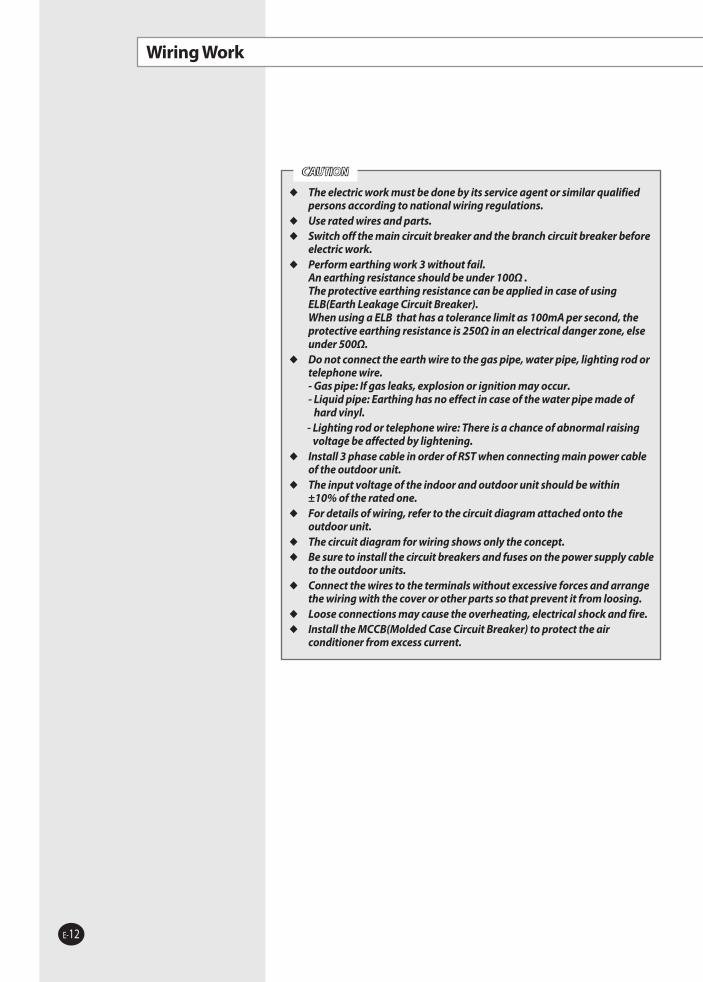
Wiring Work
The electric work must be done by its service agent or similar qualified persons according to national wiring regulations.
Use rated wires and parts. Switch off the main circuit breaker and the branch circuit breaker before
electric work. Perform earthing work 3 without fail.
An earthing resistance should be under 100Ω . The protective earthing resistance can be applied in case of using ELB(Earth Leakage Circuit Breaker). When using a ELB that has a tolerance limit as 100mA per second, the protective earthing resistance is 250Ω in an electrical danger zone, else under 500Ω.
Do not connect the earth wire to the gas pipe, water pipe, lighting rod or telephone wire. - Gas pipe: If gas leaks, explosion or ignition may occur. - Liquid pipe: Earthing has no effect in case of the water pipe made of
hard vinyl. - Lighting rod or telephone wire: There is a chance of abnormal raising
voltage be affected by lightening. Install 3 phase cable in order of RST when connecting main power cable
of the outdoor unit. The input voltage of the indoor and outdoor unit should be within
±10% of the rated one. For details of wiring, refer to the circuit diagram attached onto the
outdoor unit. The circuit diagram for wiring shows only the concept. Be sure to install the circuit breakers and fuses on the power supply cable
to the outdoor units. Connect the wires to the terminals without excessive forces and arrange
the wiring with the cover or other parts so that prevent it from loosing. Loose connections may cause the overheating, electrical shock and fire. Install the MCCB(Molded Case Circuit Breaker) to protect the air
conditioner from excess current.
CAUTION
RVXVHT080G_IM_E_24909.indd 12 2007-01-08 ソタネト 4:03:40

E-13
ENG
LISH
Wiring Work
Overall System Configuration
Connection of the power cable (3 phase 4 wires)
Connect the communication cable between indoor and outdoor units to the digital outdoor unit. (RVXVHT)
If the communication cable between indoor and outdoor units is not connected to the digital outdoor unit, communication error may occur.
Indoor power supply must be separated from outdoor power supply. Do not multiplex the communication cable to prevent communication
error.
CAUTION
Connection of the power cable (3 phase 3 wires and 1 phase 2 wires)
Switch board Outdoor unit Indoor unit
Communication cable Communication cable
3 phase 3 wires380-415V~
Earth Outdoor communication cable
Digital Fixed Fixed
Indoor communication cable
Wired remote control
Earth
1 phase 220-240V~
MCCB MCCB
MCCB
ELB
1 phase 2 wires220-240V~
ELB ELB
Switch board Outdoor unit Indoor unit
3 phase 4 wires380- 415V~
Earth Outdoor communication cable
Digital Fixed Fixed
Indoor communication cable
Wired remote control
Earth
MCCB
MCCB
1 phase 2 wires220-240V~
ELB
ELB
RVXVHT080G_IM_E_24909.indd 13 2007-01-08 ソタネト 4:03:42

E-14
Wiring Work (Continued)
Specifications of the Circuit Breaker and Power Cable
Subject Outdoor unit capacity (HP)
Model (Series) MCCB ELB Power cable
(mm2) Length (m) Earth cable (mm2)
Single unit
8 RVXVHT080G 30A 30A, 30mA, 0.1 second or less
4.0 20 or less4.0
6.0 20~50
10 RVXVHT100G 30A 30A, 30mA, 0.1 second or less
4.0 20 or less4.0
6.0 20~50
12 RVXVHT120G 40A 40A, 30mA, 0.1 second or less
6.0 20 or less6.0
10.0 20~50
14 RVXVHT140G 50A 50A, 30mA, 0.1 second or less
10.0 20 or less6.0
16.0 20~50
Subject Outdoor unit capacity (HP)
Model (Series) Quantity MCCB ELB Power cable
(mm2) Length (m) Earth cable (mm2)
Module unit
16RVXVHT080G 1
50A 50A, 30mA,0.1 second or less
10.0 20 or less6.0
RVXFHT080G 1 16.0 20~50
18RVXVHT100G 1
60A 60A, 30mA,0.1 second or less
16.0 20 or less10.0
RVXFHT080G 1 25.0 20~50
20RVXVHT100G 1
60A 60A, 30mA,0.1 second or less
16.0 20 or less10.0
RVXFHT100G 1 25.0 20~50
22RVXVHT120G 1
60A 60A, 30mA,0.1 second or less
16.0 20 or less10.0
RVXFHT100G 1 25.0 20~50
24RVXVHT140G 1
75A 75A,100mA,0.1 second or less
16.0 20 or less10.0
RVXFHT100G 1 25.0 20~50
26RVXVHT140G 1
75A 75A, 100mA,0.1 second or less
16.0 20 or less10.0
RVXFHT120G 1 25.0 20~50
28RVXVHT140G 1
75A 75A, 100mA,0.1 second or less
16.0 20 or less10.0
RVXFHT140G 1 25.0 20~50
30RVXVHT100G 1
100A 100A, 100mA,0.1 second or less
25.0 20 or less10.0
RVXFHT100G 2 35.0 20~50
32RVXVHT120G 1
100A 100A, 100mA,0.1 second or less
25.0 20 or less10.0
RVXFHT100G 2 35.0 20~50
34RVXVHT140G 1
100A 100A, 100mA,0.1 second or less
25.0 20 or less10.0
RVXFHT100G 2 35.0 20~50
36RVXVHT140G 1
100A 100A, 100mA,0.1 second or less
25.0 20 or less
10.0RVXFHT140G 135.0 20~50
RVXFHT080G 1
38RVXVHT140G 1
100A 100A, 100mA,0.1 second or less
25.0 20 or less
10.0RVXFHT140G 135.0 20~50
RVXFHT100G 1
40RVXVHT140G 1
125A 125A, 100mA,0.1 second or less
35.0 20 or less
16.0RVXFHT140G 150.0 20~50
RVXFHT120G 1
42RVXVHT140G 1
125A 125A, 100mA,0.1 second or less
35.0 20 or less16.0
RVXFHT140G 2 50.0 20~50
44RVXVHT140G 1
125A 125A, 100mA,0.1 second or less
35.0 20 or less16.0
RVXFHT100G 3 50.0 20~50
46RVXVHT140G 1
125A 125A, 100mA,0.1 second or less
35.0 20 or less16.0RVXFHT120G 1
RVXFHT100G 2 50.0 20~50
48RVXVHT140G 1
150A 150A, 100mA,0.1 second or less
50.0 20 or less
16.0RVXFHT140G 170.0 20~50
RVXFHT100G 2
RVXVHT080G_IM_E_24909.indd 14 2007-01-08 ソタネト 4:03:44

E-15
ENG
LISH
Wiring Work (Continued)
Make a knockout hole by driving in a nail. After making a knockout hole, apply rust resisting paint around
the hole. Secure the cable tube to the outdoor knockout using the CD
connector and bushing.
CAUTION
Be sure to run the power supply cable and the communication cable through electrical conduit as seen in the picture.
Protect the power and communication cable using the protection tube individually.
Power Wiring and Communication Wiring Configuration
Sort Size
Indoor and outdoor unit VCTF 0.75~1.5mm2
Remote controller VCTF0.3mm2 or more less than 200m
0.75mm2 or more 200m or more
Communication cable
In case of putting the power cable to front
MCCB
Communication cable among outdoor units
Earth
Fixed Fixed Digital
ELB
EarthPower cable
Power cable
Communication cable between indoor and outdoor units
Cable tube
Cable tubeCable tube
Front side
RVXVHT080G_IM_E_24909.indd 15 2007-01-08 ソタネト 4:03:44
E-16
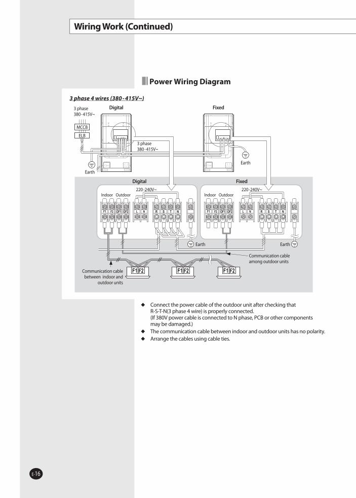
Wiring Work (Continued)
Power Wiring Diagram
Connect the power cable of the outdoor unit after checking that R-S-T-N(3 phase 4 wire) is properly connected. (If 380V power cable is connected to N phase, PCB or other components may be damaged.)
The communication cable between indoor and outdoor units has no polarity. Arrange the cables using cable ties.
3 phase 4 wires (380 - 415V~)
OF1 OF2 OF1 OF2R S T N R S T N
R S T NOF1 OF2 OF1 OF2R S T N
3 phase 380-415V~
Earth
Digital
Communication cable among outdoor units
MCCB
Fixed
3 phase380-415V~
Indoor Outdoor220-240V~
Communication cable between indoor and
outdoor units
ELB
Indoor Outdoor220-240V~
Digital Fixed
Earth
Earth Earth
RVXVHT080G_IM_E_24909.indd 16 2007-01-08 ソタネト 4:03:46

E-17
ENG
LISH
Wiring Work (Continued)
Connect the power cable of the outdoor unit after checking that R-S-T-N(3 phase 4 wire) is properly connected. (If 380V power cable is connected to N phase, PCB or other components may be damaged.)
The communication cable between indoor and outdoor units has no polarity. Arrange the cables using cable ties.
3 phase 4 wires (380 - 415V~)
OF1 OF2 OF1 OF2R S T N R S T N
R S T NOF1 OF2 OF1 OF2R S T N
3 phase 380-415V~
Earth
Digital
Communication cable among outdoor units
MCCB
Fixed
3 phase380-415V~
Indoor Outdoor220-240V~
Communication cable between indoor and
outdoor units
ELB
Indoor Outdoor220-240V~
Digital Fixed
Earth
220-240V~ power is supplied separately with outdoor unit. Cut the cables of the A part.
Connect the power cable of the outdoor unit after checking that R-S-T (3 phase 3 wire) is properly connected.
The communication cable between indoor and outdoor units has no polarity. Arrange the cables using cable ties.
Connect the communication cable among the outdoor units when installing more than 1 outdoor unit.
Connect the communication cable between indoor and outdoor units to the digital outdoor unit.
If the communication cable between indoor and outdoor units and the communication cable among outdoor units are crossed, communication is not available.
The length of the cable among the outdoor units should be under 30m or less.
CAUTIONOF1 OF2 R S T N OF1 OF2 R S T N
OF1 OF2 R S T N OF1 OF2 R S T N
Earth
Digital
Communication cable among outdoor units
MCCB 1 phase 220-240V~
Indoor Outdoor220-240V~
Communication cable between indoor and
outdoor units
3 phase 380-415V~
MCCB
1 phase 220-240V~
3 phase 380-415V~
ELB ELB
Fixed
Fixed
Indoor Outdoor220-240V~
Cut A part Cut A part
Earth
3 phase 3 wires (380 - 415V~) and 1 phase 2 wires (220-240V~)
Digital
Earth Earth
RVXVHT080G_IM_E_24909.indd 17 2007-01-08 ソタネト 4:03:51

E-18
Connecting the Power Terminal
Connect the cables to the terminal board using the compressed ring terminal. Connect the rated cables only. Connect using a driver which is able to apply the rated torque to the screws. If the terminal is loose, fire may occur caused by arc.
If the terminal is connected too firmly, the terminal may be damaged.
Wiring Work (Continued)
Separate the compressed terminal up and down to prevent it being get loosen.
Place the thin cable upward and the thick cable downward.
Secure the power cable with the cable tie.
Compressed terminal
Thin cable
Thick cable
Cable tie
Tightening Torque (kgf • cm)M4 12.0~14.7 1 phase 220V
M8 56.1~74.4 3 phase 380V
Norminal dimensions for
cable (mm2)
Norminal dimensions for
screw (mm)
B D d1 E F L d2 tStandard
dimension (mm)
Allowance (mm)
Standard dimension
(mm)
Allowance (mm)
Standard dimension
(mm)
Allowance (mm) Min. Min. Max.
Standard dimension
(mm)
Allowance (mm) Min.
4/64 9.5
±0.2 5.6 +0.3 -0.2 3.4 ±0.2 6
5 20 4.3 + 0.2 0 0.9
8 15 9 28.5 8.4 +0.40
10 8 15 ±0.2 7.1 +0.3 -0.2 4.5 ±0.2 7.9 9 30 8.4 +0.4
0 1.15
16 8 16 ±0.2 9 +0.3 -0.2 5.8 ±0.2 9.5 13 33 8.4 +0.4
0 1.45
25 8 12 ±0.3 11.5 +0.5-0.2 7.7 ±0.2 11 15 34 8.4 +0.4
0 1.78 16.5 13 8.4
35 8 16 ±0.3 13.3 +0.5-0.2 9.4 ±0.2 12.5 13 38 8.4 +0.4
0 1.88 22 13 43 8.4
50 8 22 ±0.3 13.5 +0.5-0.2 11.4 ±0.3 17.5 14 50 8.4 +0.4
0 1.8
70 8 24 ±0.4 17.5 +0.5-0.4 13.3 ±0.4 18.5 20 51 8.4 +0.4
0 2.0
Silver solder
Selecting compressed ring terminal
RVXVHT080G_IM_E_24909.indd 18 2007-01-08 ソタネト 4:03:56

E-19
ENG
LISH
Installing the Earth Wire
Earthing must be done by your installation specialist for your safety. Use the earth wire by referring to the specification of the electric cable
for the outdoor unit.
High humidity Average humidity Low humidity
Electrical potential of lower
than 150V
Perform the earthing work 3. Note 1)
The dry place Perform the earthing work 2 if possible for your safety. Note 2)
Electrical potential of
higher than 150V
Must perform the earthing work 3. Note 1)
(In case of installing circuit breaker)
Power condition
Installation place
Note 1) Earthing work 3 Earthing must be done by your installation specialist.
Check if the earthing resistance is lower than 100Ω. When installing a circuit breaker that can cut the electric circuit in case of a short circuit, the allowable earthing resistance can be 30~500Ω.
Note 2) Earthing at dry place The earthing resistance is should be lower than 100Ω.
(It should not be higher than 250Ω)
The standard of earthing may vary according to the rated voltage and installation place of the air conditioner.
Earth the power cable according to the following.
Earthing the power cable
Earth terminal
Switch board
When using earthing of the switch board
When using the terminal for earthing only
Wiring Work (Continued)
Power cable arrangement
Power cable should be arranged as shown in the picture. Assembly a wire housing containing insulation to the unit.
Each wire should not be contacted with refrigerant pipes. Use proper knockout hole to arrange wires.
CAUTION
Cable tie
Wire housingRubber Insulation
RVXVHT080G_IM_E_24909.indd 19 2007-01-08 ソタネト 4:03:58

E-20
Refrigerant Pipe Work
Install the refrigerant pipe within the maximum allowable length, difference in height and length of after the first branch pipe.
The pressure of the R410A is high. Use only rated refrigerant pipe and follow the installation method.
Use clean refrigerant pipe which there is no harmful ion, oxide, dust, iron content or moisture.
Use tools and accessories fit on R410A.
Outer diameter[mm/(inch)]
Minimum thickness
(mm)
Temper grade
ø 6.35 (1/4) 0.8
C1220T-O(Soft)
ø 9.52 (3/8) 0.8
ø12.70 (1/2) 0.8
ø15.88 (5/8) 1.0
ø19.05 (3/4) 1.0
C1220T-1/2H(Semi-hard)
ø22.23 (7/8) 1.0
ø 25.40 (1) 1.0
ø28.58 (1-1/8) 1.0
ø31.75 (1-1/4) 1.1
ø38.10 (1-1/2) 1.35
ø44.50 (1-5/8) 1.7
Temper grade and minimum thickness of the refrigerant pipe.
The total length includes elbows and joints over an allowable equivalent length. Should size up one grade of pipe between the outdoor unit and the first Y-joint.
Selecting the Refrigerant Pipe Install refrigerant pipe depending on the outdoor unit capacity. When total pipe length is more than 90m, the diameter of pipe from
the outdoor unit to the first Y-joint has to step up. Increase the refrigerant pipe up if the capacity may be reduced due to the
length of the refrigerant pipe. If you can not get a pipe of Ø25.40 in the open market,
a pipe of Ø28.58 is available instead.
Size UP (Main pipe)
First Y-joint
Make sure to use C1220T-1/2H(Semi-hard)pipe for more than Ø19.05mm. In case of using C1220T-O(Soft) pipe for Ø19.05mm, an injury may occur because of lower resistant pressure.
CAUTION
Outdoor unit capacity (HP)
Normal installation Total length is more than 90m Oil
balancing pipeLiquid side
(mm)Gas side
(mm)Liquid side
(mm)Gas side
(mm)8, 10 ø 9.52 ø 19.05 ø 12.70 ø 25.40
-12, 14 ø 12.70 ø 25.40 ø 15.88 ø 28.58
16, 18, 20, 22, 24 ø 15.88 ø 28.58 ø 19.05 ø 31.75
ø 6.3526, 28, 30, 32, 34 ø 19.05 ø 31.75 ø 22.23 ø 38.1036, 38, 40, 42,
44, 46, 48ø 19.05 ø 38.10 ø 22.23 ø 44.45
(Unit : mm)
Tool Work If compatible with conventional tool
pipe cutter
refrigerant pipe work
pipe cuttingcompatible
flaring tool pipe flaring
refrigerant oil apply refrigerant oil on flared part
ester series oil, alkyl benzene oil or synthetic oil
torque wrench connect flaring nut with pipe
compatiblepipe bender pipe bending
Nitrogen gastightening test
inhibition of oxidization
brazing tool pipe brazing
manifold gauge tightening test ~ refrigerant additional charging
vacuuming, charging and checking operation
exclusiverefrigerant charging hose
vacuum pump vacuuming unituse one which has a check valve and 5 torr degree of vacuum.
electronic scale compatible
gas leak tester gas leak test exclusive
flaring nut use indoor unit’s only
RVXVHT080G_IM_E_24909.indd 20 2007-01-08 ソタネト 4:04:01

E-21
ENG
LISH
Refrigerant Pipe Work
Allowable Length of the Refrigerant Pipe and the Installation Examples
When installing 8 indoor units
Using only Y-joint
GF
h i j k l m n
b
a
c d e f g p
Y-joint
Outdoor unit
When installing 1 outdoor unit (8HP~14HP)
GF
h i j k l m n
b
a
c d e f g p
Y-joint
Outdoor unit
When installing more than 1 outdoor unit (16HP~48HP)
Using Y-joint and branch joint
ba
c d e f g h
ik
j
Y-joint
Outdoor unit
When installing 1 outdoor unit (8HP~14HP)
Branch joint
ba
c d e f g h
ik
j
Y-joint
Outdoor unit
When installing more than 1 outdoor unit (16HP~48HP)
Branch joint
RVXVHT080G_IM_E_24909.indd 21 2007-01-08 ソタネト 4:04:03

E-22
Refrigerant Pipe Work (Continued)
Using only branch joint
b
a
c d e f g hi
Branch joint
Outdoor unit
When installing 1 outdoor unit (8HP~14HP)
b
a
c d e f g h i
Branch joint
Outdoor unit
When installing more than 1 outdoor unit (16HP~48HP)
Cautions for installing outdoor unit pipe
The connected pipe should be placed lower than service valve.
The connected pipe should be connected from the side of the air conditioner.
CAUTION
The digital variable outdoor unit of the system should be placed in the end of the pipe work circuit.
Fixed units should be installed nearest from the digital unit in larger order .
Locate the fixed outdoor unit on digital outdoor unit side which has prior main address among equal capacity fixed outdoor units.
Fixed Fixed Digital
10HP 10HP 14HP
SUB2(K13:OFF K14:ON)
SUB1(K13:ON K14:OFF)
Ex) 34HP
RVXVHT080G_IM_E_24909.indd 22 2007-01-08 ソタネト 4:04:06

E-23
ENG
LISH
Refrigerant Pipe Work (Continued)
Using only Y-joint Using Y-joint and branch joint Using only branch joint
Maximum allowable length of pipe
Outdoor unit~Indoor unit
Actual length
The distance between the outdoor unit and the furthest indoor unit ≤ 170m
Ex) Indoor unit 8 : a+b+c+d+e+f+g+p≤ 170m Ex) Indoor unit 6: a+b+h ≤ 170m Ex) Indoor unit 8: a+i ≤ 170m
Equivalent length
The distance between the outdoor and the furthest indoor unit ≤ 190m(The equivalent length of Y-joint :0.5m, The equivalent length of branch joint : 1m)
Total length The total distance from the outdoor unit to all indoor units ≤ 300m
Outdoor unit~Outdoor unit (16HP ≤ )
Actual length
The distance between the outdoor joint and the outdoor unit ≤ 10m, Equivalent length ≤ 13m
Maximum allowable height
Outdoor unit~Indoor unit Height
H1: Difference of highest between the outdoor unit and indoor unit < 50m, When the outdoor unit is lower < 40m
r≤10m(Equivalent length≤13m)s≤10m(Equivalent length≤13m)t≤10m(Equivalent length≤13m)
Indoor unit~Indoor unit Height H2: Difference of highest among the indoor units ≤ 15m
Outdoor unit~Outdoor unit Height H3: Difference of highest among the outdoor units ≤ 5m
Maximum allowable length after the first branch pipe
Actual length
The distance between the first Y-joint and the indoor unit ≤ 45mEx) Indoor unit 8 : b+c+d+e+f+g+p ≤45m/
Indoor unit 6 : b+h≤45m/Indoor unit 8 : i≤45m
The distance between the EEV kit and indoor unit ≤ 20m
Selecting the first Y-joint
Outdoor capacity (HP) Y-joint model8, 10 MXJ-YA2212
12, 14 MXJ-YA251216, 18, 20, 22, 24 MXJ-YA281526, 28, 30, 32, 34 MXJ-YA3119
36, 38, 40, 42, 44, 46, 48 MXJ-YA3819
Select the first Y-joint depending on the outdoor unit capacity. Select the other Y-joints and branch joints depending on the total capacity of attached indoor units below the selected joint individually.
Selecting the Y-joint, branch joint and outdoor joint
Outdoor jointOutdoor capacity (HP) Outdoor joint model
16 ~48 MXJ-T3819
The other Y-joint
Total capacity of attached indoor units below this Y-joint (kW)
Y-joint model
X < 22.4 MXJ-YA1509
22.4 ≤ X < 33.0 MXJ-YA2212
33.0 ≤ X < 47.0 MXJ-YA2512
47.0 ≤ X < 71.0 MXJ-YA2815
71.0 ≤ X < 104.0 MXJ-YA3119
104.0 ≤ X MXJ-YA3819
Branch joint
Total capacity of attached indoor units below this
branch joint (kW)Branch joint model
X < 47.0 MXJ-HA251247.0 ≤ X < 71.0 MXJ-HA311571.0 ≤ X MXJ-HA3819
RVXVHT080G_IM_E_24909.indd 23 2007-01-08 ソタネト 4:04:07

E-24
Refrigerant Pipe Work (Continued)
Selecting the refrigerant pipe
� ��
�
Fixed Fixed Digital
A When installing more than 1 outdoor unit and first Y-joint
B Among the outdoor units
C Outdoor unit connection
D Oil balancing pipe
B Among the outdoor units- Depend on the total capacity
of attached outdoor units.
Outdoor unit capacity (HP)
Liquid side (mm)
Gas side (mm)
X < 26 ø15.88 ø28.58
26 ≤ X < 36 ø19.05 ø31.75
36 ≤ X ø19.05 ø38.10
Outdoor unit capacity (HP)
Liquid side (mm)
Gas side (mm)
8, 10 ø9.52 ø22.23
12, 14 ø12.70 ø25.40
C Outdoor unit connection- Depend on the outdoor unit
Outdoor unit capacity (HP) All diameters (mm)
X ≥ 16 ø6.35
D Oil balancing pipe- Applicable only 16HP or more
Selecting additional refrigerant charge
Depends on the total length of the liquid side pipe.
a : Ø19.05 X 30m d : Ø9.52 X 10m g : Ø6.35 X 10m j : Ø6.35 X 10m
b : Ø15.88 X 10m e : Ø9.52 X 10m h : Ø6.35 X 10m k : Ø6.35 X 9m
c : Ø9.52 X 10m f : Ø9.52 X 10m i : Ø12.70 X 10m
A = Liquid side pipe ø22.23Total pipe length(m) X 0.35
+ Liquid side pipe ø19.05Total pipe length(m) X 0.27
+ Liquid side pipe ø15.88Total pipe length(m) X 0.18
Liquid side pipe ø12.70Total pipe length(m) X 0.125
+ Liquid side pipe ø9.52Total pipe length(m) X 0.06
+ Liquid side pipe ø6.35Total pipe length(m) X 0.02
Example of calculating additional refrigerant: In case of 30HP outdoor unit
A Installing pipes between more than 1 outdoor unit and first Y-joint - Select the size depending on the
outdoor unit capacity.
Outdoor unit total capacity (HP)
Liquid side (mm)
Gas side (mm)
8, 10 ø9.52 ø19.05
12, 14 ø12.70 ø25.40
16, 18, 20, 22, 24 ø15.88 ø28.58
26, 28, 30, 32, 34 ø19.05 ø31.75
36, 38, 40, 42, 44, 46, 48
ø19.05 ø38.10
Indoor unit total capacity (kW)
Liquid side (mm)
Gas side (mm)
X < 22.4 ø9.52 ø15.88
22.4 ≤ X < 33.0 ø9.52 ø22.23
33.0 ≤ X < 47.0 ø12.70 ø25.40
47.0 ≤ X < 71.0 ø15.88 ø28.58
71.0 ≤ X < 104.0 ø19.05 ø31.75
104.0 ≤ X ø19.05 ø 38.10
Between Y-joints- Select it depending on attached
indoor units.
+
A = 30 X 0.27 + 10 X 0.18 + 20 X 0.125 + 40 X 0.06 + 29 X 0.02 = 15.38(kg)
Pipe diameter (mm) Ø22.23 Ø19.05 Ø15.88 Ø12.70 Ø9.52 Ø6.35
Total length (m) 0 30 10 20 20 29
The amount of basic charge
HP Factory charged (kg)
8/10 6.3
12/14 7.5
Liquid side pipe (mm)
Basic charging for pipes (kg/m)
ø 6.35 0.02
ø 9.52 0.06
ø12.70 0.125
ø15.88 0.18
ø 19.05 0.27
ø 22.23 0.35
RVXVHT080G_IM_E_24909.indd 24 2007-01-08 ソタネト 4:04:09

E-25
ENG
LISH
Refrigerant Pipe Work (Continued)
Keeping Refrigerant Pipe Clean and Dry To prevent foreign materials or water from entering the pipe, it is important to
keep the refrigerant pipe and to seal it while installing.
Brazing the Pipe Make sure that there is no moisture inside the pipe. Make sure that there are no foreign materials and impurities in the pipe.
Replacement of Nitrogen gas
1 Use Nitrogen gas when brazing the pipes as shown in the picture.
2 If you don’t use Nitrogen gas when brazing the pipes, oxide may form in the pipe. It can cause the damage of the compressor, valves.
3 Adjust the flow rate of the replacement with a pressure regulator to maintain 0.05m3/h or less.
4 Perform brazing of the service valve after protecting the valve.
Brazing part
Nitrogen gas
1/4" copper pipe
Stop valve
TapingPressure regulator
Service valve
Wet towel
RVXVHT080G_IM_E_24909.indd 25 2007-01-08 ソタネト 4:04:09

E-26
Refrigerant Pipe Work (Continued)
Cutting or Flaring the Pipes
1 Make sure that you prepared the required tools. (pipe cutter, reamer, flaring tool and pipe holder)
2 If you want to shorten the pipe, cut it using a pipe cutter ensuring that the cut edge remains at 90° with the side of the pipe. There are some examples of correctly and incorrectly cut edges below.
Oblique Rough Burr
3 To prevent a gas leak, remove all burrs at the cut edge of the pipe using a reamer.
4 Carry out flaring work using flaring tool as shown below.
Outer diameter (mm)
A(mm)
Flare tool for R410A clutch type
Conventional flare toolClutch type Wing nut type
ø 6.35 0~0.5 1.0~1.5 1.5~2.0ø 9.52 0~0.5 1.0~1.5 1.5~2.0
ø 12.70 0~0.5 1.0~1.5 1.5~2.0ø 15.88 0~0.5 1.0~1.5 1.5~2.0
5 Check if you flared the pipe correctly. There are some examples of incorrectly flared pipes below.
Inclined Damaged Surface Cracked Uneven Thickness
6 Outer diameter (mm)
Connection Torque (kgf•cm)
Flare dimension (mm) Flare shape
ø 6.35 145~175 8.70~9.10
ø 9.52 333~407 12.80~13.20
ø 12.70 505~615 16.20~16.60
ø 15.88 630~769 19.30~19.70
Flaring tool
Clutch type Wing nut type
A
Die
Copper pipe
York
Die
Copper pipeFlare nut
R 0.4~0.8
90° ±
2°
45° ±
2°
In case of needing brazing, you must work with Nitrogen gas blowing.
CAUTION
RVXVHT080G_IM_E_24909.indd 26 2007-01-08 ソタネト 4:04:11
E-27
ENG
LISH
Refrigerant Pipe Work (Continued)
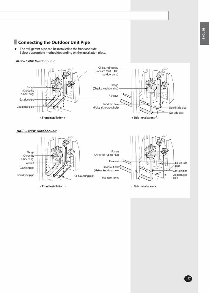
Connecting the Outdoor Unit Pipe The refrigerant pipe can be installed to the front and side.
Select appropriate method depending on the installation place.
8HP ~ 14HP Outdoor unit
Flange (Check the rubber ring)
Knockout hole(Make a knockout hole)
Flare nut
Oil balancing pipe(Not used for 8~14HP
outdoor units)
Liquid side pipe
Gas side pipe
Flange (Check the
rubber ring)
Gas side pipe
Liquid side pipe
< Front installation > < Side installation >
16HP ~ 48HP Outdoor unit
Flange (Check the
rubber ring)
Gas side pipe
Liquid side pipe
Flare nut
Oil balancing pipe
< Front installation >
Flange (Check the rubber ring)
Use accessories
Knockout hole(Make a knockout hole)
Oil balancing pipe
Liquid side pipe
Gas side pipe
Flare nut
< Side installation >
RVXVHT080G_IM_E_24909.indd 27 2007-01-08 ソタネト 4:04:12

E-28
Refrigerant Pipe Work (Continued)
Installing the Y-Joint Install the Y-joint ‘horizontally’ or ‘vertically’.
< Install horizontally>
Make certain of a minimum distance in straight line.
CAUTION
Install the Y-joint within ±15° from the horizontal or vertical line.
500mm or more
Main pipe
To outdoor unit
Pipe in use on the site
Front
Rear
Rear
Gas/Liquid side Y-joint
Pipe in use on the siteSocket
To other branching pipe or indoor unit
< Install vertically>
Note When using A~J type of Y-joint, connect the Y-joint to the pipe with provided socket.
When using K~Z type of Y-joint, connect Y-joint to the pipe by cutting the inlet of the Y-joint or provided socket properly.
10~15mmor more
RVXVHT080G_IM_E_24909.indd 28 2007-01-08 ソタネト 4:04:14

E-29
ENG
LISH
Refrigerant Pipe Work (Continued)
Installing the Branch Joint
1 Select the socket fit on the diameter of the pipe.
2 Block the socket that is not used by brazing the cap if the number of connected indoor unit is fewer than branch joint holes.
3 Install the branch joint horizontally.
- Install the branch joint horizontally so that it is not facing down.
±10° or less
Horizontal line
Socket Branch joint
Pipe used in the field
Socket
Pipe used in the field
Indoor unit side
Pipe used in the field
< Liquid side >
Outdoor unit side
Socket
Pipe used in the field
Indoor unit side
< Gas side >
Outdoor unit side
Brazing partProvided
< Gas side >
±15° or less
Horizontal line
±10° or less
Horizontal line
±15° or less
Horizontal line
< Liquid side >
Horizontal line
< Liquid side >When the end of the branch joint is sealed
In order
Brazing partProvided
Socket
When the end of the branch joint is sealed
In order
< Gas side >
Socket
Note Connect the branch joint in order respecting the number of the indoor unit. Connect the branch joint of high capacity indoor unit first among them.
When using A~J type of Branch joint, connect the Branch joint to the pipe with provided socket.
When using K~Z type of Branch joint, connect the Branch joint to the pipe by cutting the provided socket properly.
10~15mmor more
RVXVHT080G_IM_E_24909.indd 29 2007-01-08 ソタネト 4:04:16

E-30
Installing the Outdoor Joint
Refrigerant Pipe Work (Continued)
Use the attached socket at the liquid side along with the selected pipe size.
Pipe in use on the site
Socket at the liquid side
Socket at the liquid side
Pipe in use on the site
To other outdoor unit
To other outdoor joint or Y-joint of the main pipe
<Liquid side>
To other outdoor joint or outdoor unit
Installation of outdoor joints
Digital outdoor unit
Fixed outdoor unit
Liquid pipe Gas pipe Oil balancing joint
Digital outdoor unit
Fixed outdoor unit
Do not install the outdoor joint in this direction.
Gas pipe connection part
Liquid pipe connection part
Oil balancing joint connection part
Use the attached socket at the gas side along with the selected pipe size.
Note When using A~J type of Outdoor joint, connect the Outdoor joint to the pipe with provided socket.
When using K~Z type of Outdoor joint, connect the Outdoor joint to the pipe by cutting provided socket properly.
10~15mmor more
Pipe in use on the site
Socket at the gas side
Socket at the gas side
Pipe in use on the site
To other outdoor unit
To other outdoor joint or Y- joint of the main pipe
To other outdoor unit
To other outdoor joint or outdoor unit
<Gas side>
To other outdoor joint or outdoor unit
RVXVHT080G_IM_E_24909.indd 30 2007-01-08 ソタネト 4:04:18
E-31
ENG
LISH
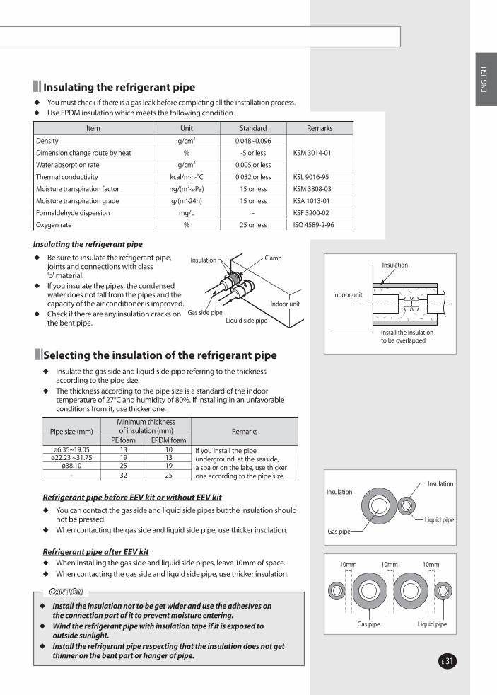
Insulating the refrigerant pipe You must check if there is a gas leak before completing all the installation process. Use EPDM insulation which meets the following condition.
Item Unit Standard Remarks
Density g/cm3 0.048~0.096
KSM 3014-01Dimension change route by heat % -5 or less
Water absorption rate g/cm3 0.005 or less
Thermal conductivity kcal/m·h·˚C 0.032 or less KSL 9016-95
Moisture transpiration factor ng/(m²·s·Pa) 15 or less KSM 3808-03
Moisture transpiration grade g/(m²·24h) 15 or less KSA 1013-01
Formaldehyde dispersion mg/L - KSF 3200-02
Oxygen rate % 25 or less ISO 4589-2-96
Insulating the refrigerant pipe
Be sure to insulate the refrigerant pipe, joints and connections with class 'o' material.
If you insulate the pipes, the condensed water does not fall from the pipes and the capacity of the air conditioner is improved.
Check if there are any insulation cracks on the bent pipe.
Insulation
Install the insulation to be overlapped
Indoor unit
Refrigerant Pipe Work (Continued)
Selecting the insulation of the refrigerant pipe Insulate the gas side and liquid side pipe referring to the thickness
according to the pipe size. The thickness according to the pipe size is a standard of the indoor
temperature of 27°C and humidity of 80%. If installing in an unfavorable conditions from it, use thicker one.
Refrigerant pipe before EEV kit or without EEV kit
You can contact the gas side and liquid side pipes but the insulation should not be pressed.
When contacting the gas side and liquid side pipe, use thicker insulation.
Refrigerant pipe after EEV kit When installing the gas side and liquid side pipes, leave 10mm of space. When contacting the gas side and liquid side pipe, use thicker insulation.
Install the insulation not to be get wider and use the adhesives on
the connection part of it to prevent moisture entering. Wind the refrigerant pipe with insulation tape if it is exposed to
outside sunlight. Install the refrigerant pipe respecting that the insulation does not get
thinner on the bent part or hanger of pipe.
CAUTION
Pipe size (mm)Minimum thickness of insulation (mm) Remarks
PE foam EPDM foamø6.35~19.05 13 10 If you install the pipe
underground, at the seaside, a spa or on the lake, use thicker one according to the pipe size.
ø22.23 ~31.75 19 13ø38.10 25 19
- 32 25
Insulation
Gas pipe
Liquid pipe
Insulation
Gas pipe
10mm
Liquid pipe
10mm 10mm
Insulation
Gas side pipeLiquid side pipe
Indoor unit
Clamp
RVXVHT080G_IM_E_24909.indd 31 2007-01-08 ソタネト 4:04:21

E-32
Performing the Refrigerant Gas Leak Test
Use tools for R410A to prevent the inflow of foreign substances and resist against the internal pressure.
Do not remove the core of filling port. Use dry Nitrogen gas as doing an airtight test like below.
Apply pressure to the liquid side pipe, gas side pipe and oil balancing pipe(16HP or more) with Nitrogen gas of 4.1MPa(41kgf/cm²)
If you apply pressure more than 4.1MPa(41kgf/cm²), the pipes may be damaged. Apply pressure using pressure regulator.
Keep it for minimum 24 hours to check if the pressure drops.
After applying Nitrogen gas, check the change of pressure using pressure regulator.
If the pressure drops, check if there’s gas leak. If the pressure is changed, apply soapy water to check the leak. Check the pressure of the gas again.
Maintain 10kgf/cm² of the pressure before performing vacuum drying and check further gas leak.
After checking first gas leak, maintain 10kgf/cm² to check further gas leak.
Manifold gage
High pressure sideLow pressure side
Nitrogen gas
Filling port
Gas side pipeOil balancing pipe
Liquid side pipe
RVXVHT080G_IM_E_24909.indd 32 2007-01-08 ソタネト 4:04:21

E-33
ENG
LISH
Preparing and Charging the Refrigerant Pipe
Vacuum Drying Use the tools for R410A to prevent the inflow of foreign substances and resist
against the internal pressure. Vacuum system to 5Torr (100.7KPa, 755mmHg). Use the vacuum pump with the check valve to prevent pump oil from flowing
backward while the vacuum pump is stopped. Close the service valve of the liquid side pipe, gas side pipe and oil balancing
pipe completely.
The pressure rises.
No
Connect the manifold gauge to the liquid side pipe, gas side pipe and oil balancing pipe(16HP or more).
Connect the manifold gauge to the oil balancing pipe when using the outdoor unit of 16HP or more.
Perform vacuum drying of the liquid side pipe, gas side pipe and oil balancing pipe(16HP or more) using the vacuum pump.
Make sure that install check valve to prevent pump oil from flowing into the pipe.
Perform vacuum drying for 2 hours and 30 minutes or more.
The time of vacuum drying may differ depending on the length of the pipe or outdoor temperature. Perform vacuum drying for at least 2 hours and 30 minutes.
Close the valve after checking the vacuum gauge pressure has reached at 5Torr. Check the vacuum pressure using the vacuum gauge.
Adding refrigerant
Check the gas leak part.
- The pressure rises because water is remaining in the pipe.
Vacuum destruction
- Apply pressure with Nitrogen gas of 0.5kgf/cm².
Perform vacuum drying again up to 5Torr (for 2 hours or more).
Yes
The pressure rises.YesNo
RVXVHT080G_IM_E_24909.indd 33 2007-01-08 ソタネト 4:04:22

E-34
Preparing and Charging the Refrigerant Pipe (Continued)
Charging Refrigerant The R410A refrigerant is blended refrigerant. Add only liquid refrigerant. Measure the quantity of the refrigerant depending on the length of the liquid
side pipe. Add fixed quantity of the refrigerant using a scale.
When installing 1 outdoor unit(8HP ~ 14HP)
Gas side
Scale
R410A
Liquid side
Vacuum pump
Manifold gauge
Service valve
Outdoor unit
When installing more than 1 outdoor unit(16HP ~ 48HP)
Gas side
Scale
R410A
Oil equalization
Vacuum pump
Manifold gauge
Service valve
Outdoor unit
Liquid side
Open the gas side and liquid side service valve completely after charging the refrigerant. (If you operate the air conditioner with the service valve closed, the important parts may be damaged.)
When using the outdoor unit of 16HP or more, open the service valve of the oil balancing pipe.
CAUTION
Open the manifold gauge valve of the liquid side service valve and add the liquid refrigerant.
If you cannot add the whole quantity of the refrigerant while the outdoor unit is stopped, open the gas side and liquid side service valve. Add remaining refrigerant by pressing the refrigerant adding button of the outdoor PCB.
RVXVHT080G_IM_E_24909.indd 34 2007-01-08 ソタネト 4:04:22
E-35
ENG
LISH
Preparing and Charging the Refrigerant Pipe (Continued)
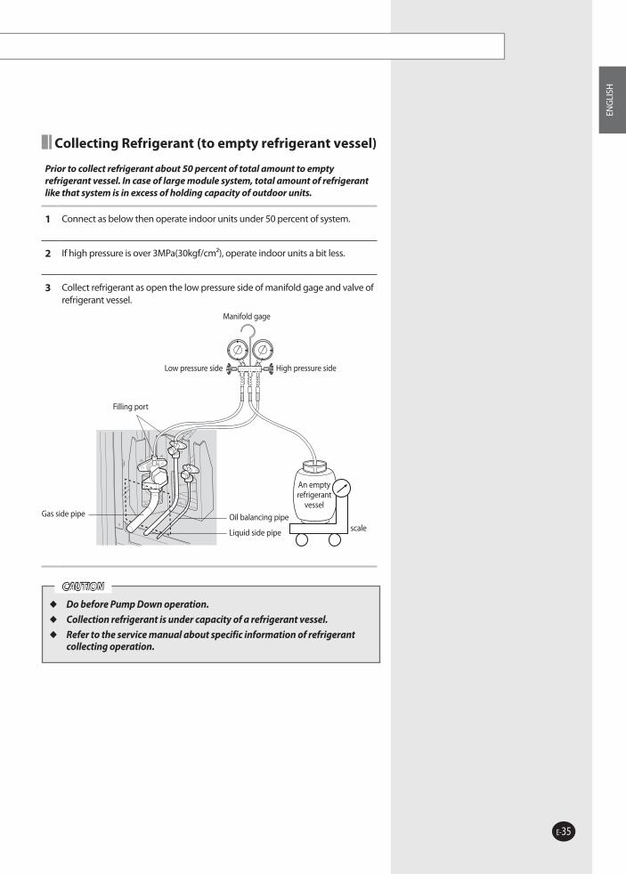
Collecting Refrigerant (to empty refrigerant vessel)
Prior to collect refrigerant about 50 percent of total amount to empty refrigerant vessel. In case of large module system, total amount of refrigerant like that system is in excess of holding capacity of outdoor units.
1 Connect as below then operate indoor units under 50 percent of system.
2 If high pressure is over 3MPa(30kgf/cm²), operate indoor units a bit less.
3 Collect refrigerant as open the low pressure side of manifold gage and valve of refrigerant vessel.
Manifold gage
High pressure sideLow pressure side
An empty refrigerant
vessel
scale
Filling port
Gas side pipe Oil balancing pipe
Liquid side pipe
Do before Pump Down operation.
Collection refrigerant is under capacity of a refrigerant vessel.
Refer to the service manual about specific information of refrigerant collecting operation.
CAUTION
RVXVHT080G_IM_E_24909.indd 35 2007-01-08 ソタネト 4:04:23

E-36
Switch Setting Function Remarks
SW01SW02
Combine SW01 and SW02ex) SW01-1, SW02-2 : 12 indoor units
are installed
To set the total quantity of installed indoor units
Set only for digital outdoor unit
SW03
K5ON Manual address setting
Indoor unit main address setting method select
If it is selected OFF, indoor unit main address sets automaticallyOFF Auto address setting
K6ON Comp.1 normal operation
Back-up operation while compressor broken
Compressor should be replaced as soon as possible
OFF Comp.1 operation skip
K7ON Comp.2 normal operation
OFF Comp.2 operation skip
K8ON Comp.3 normal operation
OFF Comp.3 operation skip
SW05
K13 ONSet as main outdoor unit Main unit set Set only digital outdoor unit
K14 ON
K13 ONSet as sub1 outdoor unit Sub unit set The next digital outdoor unit
K14 OFF
K13 OFFSet as sub2 outdoor unit Sub unit set The next sub 1 unit
K14 ON
K13 OFFSet as sub3 outdoor unit Sub unit set The next sub 2 unit
K14 OFF
SW06
The furthest length between outdoor unit and indoor unit: Max. length
K17 ONMax. length≤30m Pressure drop compensation Factory setting
K18 ON
K17 ON30m<Max. length≤80m Pressure drop compensation
K18 OFF
K17 OFF80m<Max. length Pressure drop compensation
When the pipe is increased up between outdoor unit and first Y-jointK18 ON
K17 OFF80m<Max. length Pressure drop compensation
K18 OFF
Setting the Option Switch and Function of the Keys
Option switches in PCB of the outdoor unit
K5
SW01 SW02 SW03 SW04 SW05 SW06
K6 K7 K8 K9 K10 K11 K12 K13 K14 K15 K16 K17 K18 K19 K20 K21 K22 K23 K24
RVXVHT080G_IM_E_24909.indd 36 2007-01-08 ソタネト 4:04:25

E-37
ENG
LISH
Setting the Option Switch and Function of the Keys
K1 (Number of pressing) Name Function Display on LED
1 Adding refrigerant in heating mode When adding refrigerant to the unit
2 Test operation for heating When conduct a test run on heating mode
3 Refrigerant discharge from Main unit To repair the main unit
4 Refrigerant discharge from Sub1 unit To repair the sub1 unit
5 Refrigerant discharge from Sub2 unit To repair the sub2 unit
6 Refrigerant discharge from Sub3 unit To repair the sub3 unit
7 Oil recovery to outdoor unit in heating
Oil return from pipe to the outdoor unit
8 Set Main unit for vacuum mode Main unit to be ready for vacuum after repair
9 Set Sub1 unit for vacuum mode Sub1 unit to be ready for vacuum after repair
10 Set Sub2 unit for vacuum mode Sub2 unit to be ready for vacuum after repair
11 Set Sub3 unit for vacuum mode Sub3 unit to be ready for vacuum after repair
12 Set all units for vacuum mode All units to be ready for vacuum after repairing
13 Finish K1 mode End of K1 mode
Key operation
Check mode RESET View mode
K2 (Number of pressing) Name Function Display on LED
1 Adding refrigerant in cooling mode When adding refrigerant to the unit
2 Test operation for cooling When conduct a test run on cooling mode
3 Refrigerant collection to All unit To repair indoor unit, pipe and so on
4 Oil recovery to outdoor unit in cooling
Oil return from pipe to the outdoor unit
5 Finish K2 mode End of K2 mode
K3 (Number of pressing) Name Function Remarks
1 Reset the unit To reset the unit
K4 (Number of pressing) Name Function Remarks
- Data display Display datas of outdoor unit in operation
For further information, see the label on the outdoor unit.
RVXVHT080G_IM_E_24909.indd 37 2007-01-08 ソタネト 4:04:29

E-38
Setting the Option Switch and Function of the Keys (Continued)
Setting process of the PCB built into the outdoor unit
Set the number of total quantity of installed indoor units. By the combination of SW01 and SW02
Set the main address of the indoor address. K5 ON - Manual setting methodK5 OFF- Automatic setting method
Set the main and sub outdoor unit. By the combination of SW05, K13 and K14
Pressure drop compensation according to pipe length By the combination of SW06, K17 and K18
Completing the Installation
Installation
Outdoor unit
Check the external surface and the inside of the outdoor unit. Is there any possibility of short circuit? Is the place well-ventilated and ensures space for service? Is the outdoor unit fixed securely?
Indoor unit Check the external surface and the inside of the indoor unit. Is the place well-ventilated and ensures space for service? Check if the center of the indoor unit is ensured and it is installed horizontally.
Refrigerant pipe work
Is total number of connecting indoor units in the allowable range? Are the length and the difference between the refrigerant pipes within the allowable range? Is the Y-joint properly installed? Is the pipe properly insulator? Is the quantity of the additional refrigerant correctly weighed in?
Installing the drain pipe Check the drain pipe of the outdoor unit and the indoor unit. Have you completed the drain test? Is the drain pipe properly insulated?
Installing the wiring
Have you performed the earthing work 3 to the outdoor unit? Is 2-core cable used? Is the length of the wire is in the limited range? Is the wiring route correct?
Setting ADDRESS Are the ADDRESSES of the indoor and outdoor unit properly set? Is the ADDRESSES switch of the remote control properly installed? (When using more than 1 remote control)
Option Check if the square pad is installed properly when the outdoor unit may vibrate.
Check the following after completing the installation.
RVXVHT080G_IM_E_24909.indd 38 2007-01-08 ソタネト 4:04:30

E-39
ENG
LISH
Final Checks and Trial Operation
Turn the circuit breaker on 6 hours before initial operation so the crank case heater can be heated enough to start the system.
If the heater is not heated, the air conditioner does not operate for 2 hours and 30 minutes to protect the compressor. (‘CH’ is displayed on the PCB display of the outdoor unit)
CAUTION
Inspection before test operation
1 Check the power cable and communication cable of the indoor and outdoor unit.
2 Turn the circuit breaker(3 phases and 1 phase) on 6 hours before initial operation so that the crank case heater can be heated.
3 Check the power supply between the outdoor unit and the cabinet panel.
Check the 3 phase power of the compressor {L1(Red), L2(White), L3(Black)} by the 3 phase tester.
Check the 220V power with the voltage meter.
4 Once the outdoor unit is turned on, it performs the tracking to check the connected indoor unit and options.
Test operation
1 Run the unit by KEY MODE or controller.
1st- Running all indoor units by KEY MODE 2nd- Each indoor unit run separately by controller
Inspect the compressor sound during the initial operation. If roaring sound is heard, stop operation.
If roaring sound is heard and the pressure does not change, the back-lashing of the compressor may occur. Check the power supply of the compressor. If the problem occurs continuously, check the compressor power cable. 3 phase:T1(L1)(R)-Red, T2(L2)(S)-White, T3(L3)(T)-Black
2 Check the indoor and outdoor units’ running status.Check indoor unit cooling and heating air flow Each indoor unit controls: air flow direction, air velocityIndoor and outdoor unit’s abnormal running noiseProper drainage from indoor unit in cooling modeCheck detail running status using S-NET program.
3 Finish test.
4 Explain to the customer how to use the air conditioner following the user’s manual.
RVXVHT080G_IM_E_24909.indd 39 2007-01-08 ソタネト 4:04:30

RVXVHT080G_IM_E_24909.indd 40 2007-01-08 ソタネト 4:04:30


![Bonctermi gyakorlat Apparatus uropoeticus17users.atw.hu/aokszote/download.php?fname=./01] ALAPOZO MODUL/anatomia... · Bonctermi gyakorlat Apparatus uropoeticus20 ii) Syntopia - lumbalis](https://static.fdocument.pub/doc/165x107/5e1cee9baf83b5118f0799d6/bonctermi-gyakorlat-apparatus-alapozo-modulanatomia-bonctermi-gyakorlat-apparatus.jpg)