Reduction of Piston Slap Excitation by Optimizing Piston ... · 3.2.Lubrication Film Reaction...
7
REDUCTION OF PISTON SLAP EXCITATION BY OPTIMIZING PISTON PROFILES Takayuki KOIZUMI, Nobutaka TSUJIUCHI, Masahiro OKAMURA, and Hisashi TSUKIJIMA Department of Engineering. Doshisha University, Kyoto, Japan Isamu KUBOMOTO, Eiichi ISHIDA Kubota Corporation Sakai, Osaka, Japan ABSTRACT This paper presents an analytical model for the prediction of piston secondary motion and the vibration due to piston slap. For the modeling of piston slap phenomenon, cylinder liner is modeled as a several spring-mass system that are connected by modal characteristics, and lubricant film between the piston and the cylinder is modeled as reaction force vectors which excite resonant mode of them. By comparing experimental results and analytical ones, the validity of the proposed model has been confirmed. The optimization of the piston skirt profile is also carried out with the analytical model, and it is confirmed that the round shape of the lower part of piston skirt is effective for the reduction of piston slap excitation. 1.INTRODUCTION Small air-cooled gasoline engines are used around us as small farm machineries, pumps, generators and so on. However, in some case, noises radiated from them exceed the acceptable noise level and they causes serious problems for the operators. Therefore, in recent years, low noise and low vibration has been required more strongly for present engines. This paper presents an analytical model for the prediction of the vibration of the cylinder wall caused by piston slap phenomenon and the optimization of the piston skirt profile for the reduction of the vibration. For the analytical model, the characteristics of lubrication film are one of the key factors to simulate the piston secondary motion [1-3]. On the other hand, the dynamic characteristics of cylinder walls are also of great importance [4-5]. Nevertheless, no method that takes both of them into account is found. In this study, we propose an analytical model for the coupled system of piston and cylinder wall via lubricant to simulate the behavior of piston inside a cylinder wall and the vibration response. 2.MMEASUREMENT OF THE PISTON BEHAVIOR The piston behavior in the cylinder is measured for the comprehension of piston slap phenomenon. The experimental setup is shown in Fig.1. The measurement on the test engine for generators is carried out in the condition of rated engine speed 3600[rpm], and rated load 3.6[kW]. 2.1.Experimental Setup In order to measure the behavior of piston, four eddy current gap sensors that measure the clearance between piston skirt and cylinder are embedded in the each edge of piston skirt. The locations of the sensors are shown in Fig.2. The signals from the sensors are lead out of engine via connecting rod and a linkage system. The linkage system is shown in Fig.3. In order to estimate the crank angle, an inductive pickup is attached on the spark plug, and the cylinder pressure is measured by means of a pressure sensor, that is installed in the spark plug. ONO-SOKKI FFT ANALYZER TEACInductive Pickup Pressure Transducer Load 3.6[Kw] IGNITION SIGNAL CYLINDER PRESSURE GASOLINE ENGINE with GENERATOR CHARGE AMPLIFIER GAP SENSOR AMPLIFIER FFT ANALYZER ONO-SOKKI FFT ANALYZER DAT RECORDER GAIN ZERO LINEAR V 55MS-M CLEARANCE TEMPERATURE Fig.1. Set-up for tne Measurement of Piston Behavior 5[mm] 8[mm] 5[mm] 8[mm] GAP SENSORS Fig.2. Locations of the Gap Sensors in the Piston Skirt 107
Transcript of Reduction of Piston Slap Excitation by Optimizing Piston ... · 3.2.Lubrication Film Reaction...
REDUCTION OF PISTON SLAP EXCITATION BY OPTIMIZING PISTON PROFILES
Takayuki KOIZUMI, Nobutaka TSUJIUCHI, Masahiro OKAMURA, and Hisashi TSUKIJIMA
Department of Engineering. Doshisha University, Kyoto, Japan
Isamu KUBOMOTO, Eiichi ISHIDA Kubota Corporation
Sakai, Osaka, Japan
ABSTRACT
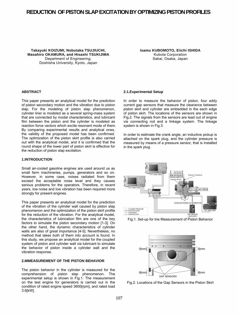
This paper presents an analytical model for the prediction of piston secondary motion and the vibration due to piston slap. For the modeling of piston slap phenomenon, cylinder liner is modeled as a several spring-mass system that are connected by modal characteristics, and lubricant film between the piston and the cylinder is modeled as reaction force vectors which excite resonant mode of them. By comparing experimental results and analytical ones, the validity of the proposed model has been confirmed. The optimization of the piston skirt profile is also carried out with the analytical model, and it is confirmed that the round shape of the lower part of piston skirt is effective for the reduction of piston slap excitation.
1.INTRODUCTION
Small air-cooled gasoline engines are used around us as small farm machineries, pumps, generators and so on. However, in some case, noises radiated from them exceed the acceptable noise level and they causes serious problems for the operators. Therefore, in recent years, low noise and low vibration has been required more strongly for present engines.
This paper presents an analytical model for the prediction of the vibration of the cylinder wall caused by piston slap phenomenon and the optimization of the piston skirt profile for the reduction of the vibration. For the analytical model, the characteristics of lubrication film are one of the key factors to simulate the piston secondary motion [1-3]. On the other hand, the dynamic characteristics of cylinder walls are also of great importance [4-5]. Nevertheless, no method that takes both of them into account is found. In this study, we propose an analytical model for the coupled system of piston and cylinder wall via lubricant to simulate the behavior of piston inside a cylinder wall and the vibration response.
2.MMEASUREMENT OF THE PISTON BEHAVIOR
The piston behavior in the cylinder is measured for the comprehension of piston slap phenomenon. The experimental setup is shown in Fig.1. The measurement on the test engine for generators is carried out in the condition of rated engine speed 3600[rpm], and rated load 3.6[kW].
2.1.Experimental Setup
In order to measure the behavior of piston, four eddy current gap sensors that measure the clearance between piston skirt and cylinder are embedded in the each edge of piston skirt. The locations of the sensors are shown in Fig.2. The signals from the sensors are lead out of engine via connecting rod and a linkage system. The linkage system is shown in Fig.3.
In order to estimate the crank angle, an inductive pickup is attached on the spark plug, and the cylinder pressure is measured by means of a pressure sensor, that is installed in the spark plug.
POWERO N
O FF
SYSTEMRES ET
ONO-SOKKI 4 CHANNEL INTELLIGENT FFT ANALYZER CF6400
1 C HT R IGSIG OUT
OVER-12dB
2 C H
OVER-12dB
3 C H
OVER-12dB
4 C H
OVER-12dB
CURSOR & DISPLAY MEMORY
COMMAND
MEASUREMENT
INPUT
FFT ANALYZER
TEAC RD-1 35T DAT RECORDER
Inductive Pickup
Pressure Transducer
Load 3.6[Kw]
IGNITION SIGNALCYLINDER PRESSURE
GASOLINE ENGINE with GENERATOR
CHARGE AMPLIFIER
GAP SENSORAMPLIFIER
FFT ANALYZER
POWERO N
O FF
SYSTEMRESET
ONO-SOKKI 4 CH ANNEL IN TE LLIGENT FFT ANALYZER CF6400
1 C HT R IGSIG OUT
OVER-12dB
2 C H
OVER-12dB
3 C H
OVER-12dB
4 C H
OVER-12dB
CURSOR & DISPLAY MEMORY
COMMAND
MEASUREMENT
INPUT
FFT ANALYZER
DAT RECORDER
GAIN1 0
60
2 0
70
30
8040
9 0
50
00
7 6 5
ZERO1 0
60
2 0
70
30
8040
90
50
00
76
5
LINEAR1 0
60
2 0
70
30
804
0
9 0
50
00
7 6 5
V
55MS-M RCLEARANCETEMPERATURE Fig.1. Set-up for tne Measurement of Piston Behavior
5[mm]
8[mm]
5[mm]
8[mm]GAP SENSORS
Fig.2. Locations of the Gap Sensors in the Piston Skirt
107

Fig.3. Linkage system for Leading the Signals
3.ANALYTICAL MODEL FOR PISTON SECONDARY MOTION
For the prediction of piston slap phenomenon, an analytical model that consists of lubrication film and modal characteristics of the cylinder liner is built. The model is based on a two-dimentional lumped mass model, and constant crank rotation is assumed. The program is coded in FORTRAN, and the Newmark Beta Method is employed for obtaining the time history response.
3.1.Governing Equation
The coordinate system for the reciprocating machinery is shown in Fig.4, where α is crank angle, px and py is the
lateral and vertical displacement of pistion pin, pθ is the
tilt of piston, and β is the tilt of connecting rod.
The vertical displacement py can be represented as a
function of crank angle α and tilt of connecting rod β as follows;
)()coscos( rllry p +−+= βα (1)
And the vertical acceleration of piston pin is derived as follows;
ββββαω cossincos 222
2&&& llr
dt
yd p −−−= (2)
In operating conditions, combustion force gF , frictions
between piston ring and cylinder liner rlF , frictions between piston and cylinder plF , the connecting rod
reaction force lF and the friction torque between piston pin and connecting rod pT act on piston as shown in Fig.5.
From the balance of the forces, following equations are derived.
βθ
θ
sinsin
)( 2
2
2
2
lcouplepg
pyp
ppinrp
FFFWdtd
Gmdtxd
mmm
+++=
−++
∑ (3)
Thrust Side Antithrust Side
py
α
θ
0
y
x
opx oBx
pθ
l
r
rl +
β
Fig.4. Coordinate System of Reciprocating Machinery
w
w pinr mm +
pm
rgm rlFrlF
plF
plF
pTlF
coupleFyGxG
opx
β
gF Antithrust SideThrust Side
sixsiy
rix
Fig.5. Forces act on Piston
gmmmmFFFF
dtd
Gmdtyd
mmmm
rgpinrp
rlpllpg
pxp
prgpinrp
)( coscos
)( 2
2
2
2
+++−
∑−∑−+−=
++++
βθ
θ
(4)
oprgxpp
rirlsiplopgsi
py
pxp
ppinp
gxmgGmT
xFxFxFWy
dtxd
Gdtyd
Gmdtd
II
−−+
−−−−=
−++
∑∑∑
)( 2
2
2
2
2
2θ
(5)
where pm is the mass of the piston, rm is the mass of
the small-end of the connecting rod, pinm is the mass of
the piston pin, rgm is the mass of the piston ring, pI is the
moment of inertia, pinr is the radius of piston pin,
yx GG , are the offset of center of gravity from the center of
the piston pin and opx is the horizontal offset of the piston
pin from the center of piston. six and siy are the location of the i -th collision point of the piston, that are defined on the piston skirt and the cylinder liner. By solving these equations and carrying out time history integration, the piston behavior can be calculated.
108
3.2.Lubrication Film Reaction Forces act between Piston Skirt and Cylinder Liner
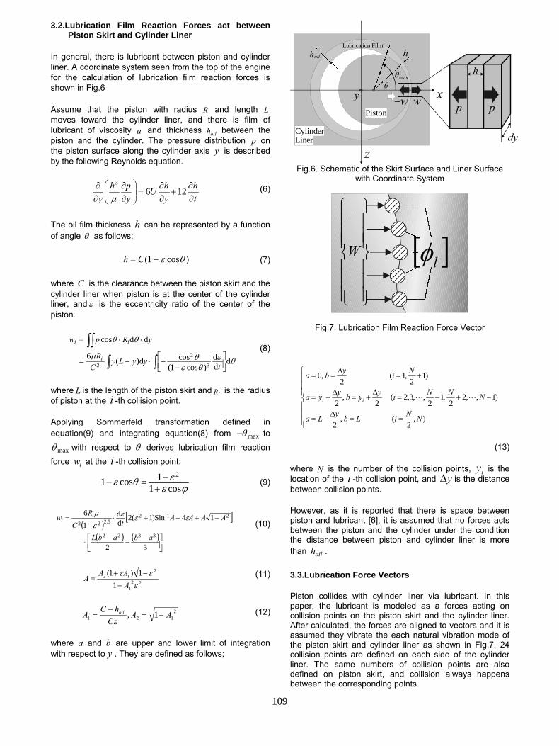
In general, there is lubricant between piston and cylinder liner. A coordinate system seen from the top of the engine for the calculation of lubrication film reaction forces is shown in Fig.6
Assume that the piston with radius R and length L moves toward the cylinder liner, and there is film of lubricant of viscosity µ and thickness oilh between the piston and the cylinder. The pressure distribution p on the piston surface along the cylinder axis y is described by the following Reynolds equation.
th
yhU
yph
y ∂∂
+∂∂
=
∂∂
∂∂ 126
3
µ (6)
The oil film thickness h can be represented by a function of angle θ as follows;
)cos1( θε−= Ch (7)
where C is the clearance between the piston skirt and the cylinder liner when piston is at the center of the cylinder liner, and ε is the eccentricity ratio of the center of the piston.
∫∫∫∫
−−⋅−=
⋅⋅=
θεθεθµ
θθ
ddd
)cos1(cosd)(6
ddcos
3
2
2 tyyLy
CR
yRpw
i
ii (8)
where L is the length of the piston skirt and iR is the radius of piston at the i -th collision point.
Applying Sommerfeld transformation defined in equation(9) and integrating equation(8) from maxθ− to
maxθ with respect to θ derives lubrication film reaction force iw at the i -th collision point.
ϕεεθεcos1
1cos12
+−=− (9)
( )[ ]
( ) ( )
−−−⋅
−+++⋅−
=
32
14Sin)1(2dd
16
3322
21-25.222
ababL
AAAAtC
Rw ii εεε
εµ
(10)
221
212
11)1(ε
εεAAAA
−−+
= (11)
2121 1, AA
ChC
A oil −=−
=ε
(12)
where a and b are upper and lower limit of integration with respect to y . They are defined as follows;
y xθ
z
Piston
h
dy
w
maxθ
hoilhLubrication Film
w− p p
LinerCylinder
Fig.6. Schematic of the Skirt Surface and Liner Surface with Coordinate System
[ ]lφ
W
Fig.7. Lubrication Film Reaction Force Vector
==∆
−=
−+−=∆
+=∆
−=
+=∆
==
),2
(,2
)1,,22
,12
,,3,2(2
,2
)12
,1(2
,0
NNiLbyLa
NNNiyybyya
Niyba
ii LL
(13)
where N is the number of the collision points, iy is the location of the i -th collision point, and y∆ is the distance between collision points.
However, as it is reported that there is space between piston and lubricant [6], it is assumed that no forces acts between the piston and the cylinder under the condition the distance between piston and cylinder liner is more than oilh .
3.3.Lubrication Force Vectors
Piston collides with cylinder liner via lubricant. In this paper, the lubricant is modeled as a forces acting on collision points on the piston skirt and the cylinder liner. After calculated, the forces are aligned to vectors and it is assumed they vibrate the each natural vibration mode of the piston skirt and cylinder liner as shown in Fig.7. 24 collision points are defined on each side of the cylinder liner. The same numbers of collision points are also defined on piston skirt, and collision always happens between the corresponding points.
109
3.4.Model of Cylinder Liner
For the prediction of the vibration induced by piston slap, the modal characteristics of the cylinder liner are of great importance. The coupled vibration is represented by the linear combination of natural vibration modes as follows;
∑=
=++=N
iiiNN uuu
111 ΦΦΦx L (14)
where ),,1( Nii L=Φ is the i -th mode shape vector and iu is the response of i -th mode.
The dynamics equation that is normalized by mass for cylinder liner is derived as following;
( )
′=
+
+
llrlrl ff WuuuO
O
&
O
O
&&
O
O2241 πζπ
(15)
where rf is the natural frequency of the r -th mode and rζ is the loss factor of the r -th mode.
By carrying out the time history integration, the response of the i -th mode iu after a small time step is derived. By composing them by means of equation (14), the response of the cylinder liner in physical coordinate system lx is derived. And by calculating in the same way, the response of piston skirt can be derived. The modal parameters of piston skirt and cylinder liner are obtained by hammer test.
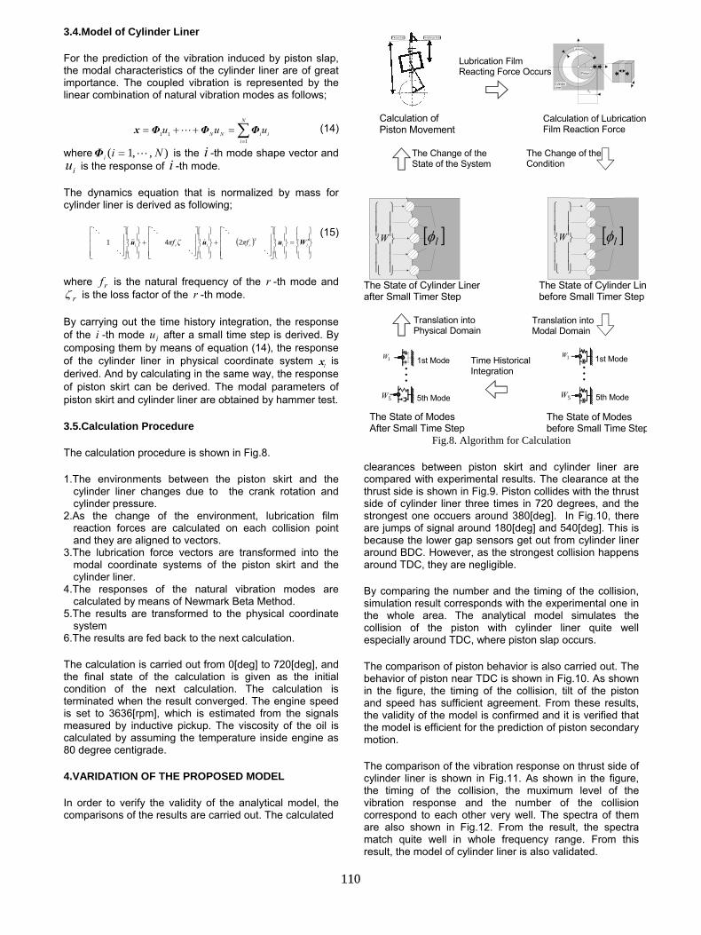
3.5.Calculation Procedure
The calculation procedure is shown in Fig.8.
1.The environments between the piston skirt and the cylinder liner changes due to the crank rotation and cylinder pressure.
2.As the change of the environment, lubrication film reaction forces are calculated on each collision point and they are aligned to vectors.
3.The lubrication force vectors are transformed into the modal coordinate systems of the piston skirt and the cylinder liner.
4.The responses of the natural vibration modes are calculated by means of Newmark Beta Method.
5.The results are transformed to the physical coordinate system
6.The results are fed back to the next calculation.
The calculation is carried out from 0[deg] to 720[deg], and the final state of the calculation is given as the initial condition of the next calculation. The calculation is terminated when the result converged. The engine speed is set to 3636[rpm], which is estimated from the signals measured by inductive pickup. The viscosity of the oil is calculated by assuming the temperature inside engine as 80 degree centigrade.
4.VARIDATION OF THE PROPOSED MODEL
In order to verify the validity of the analytical model, the comparisons of the results are carried out. The calculated
The Change of the Condition
Translation into Modal Domain
M1W
5W
1st Mode
5th Mode
Time Historical IntegrationM
1W
5W
1st Mode
5th Mode
Translation into Physical Domain
The Change of the State of the System
Lubrication Film Reacting Force Occurs
The State of Modes After Small Time Step
Calculation of Lubrication Film Reaction Force
The State of Cylinder Linebefore Small Timer Step
The State of Modes before Small Time Step
The State of Cylinder Linerafter Small Timer Step
Calculation of Piston Movement
sx
Lubricant
Piston
Cylinder Liner
[ ]lφ
W [ ]lφ
W
Thrust Side Antithrust Side
Fig.8. Algorithm for Calculation
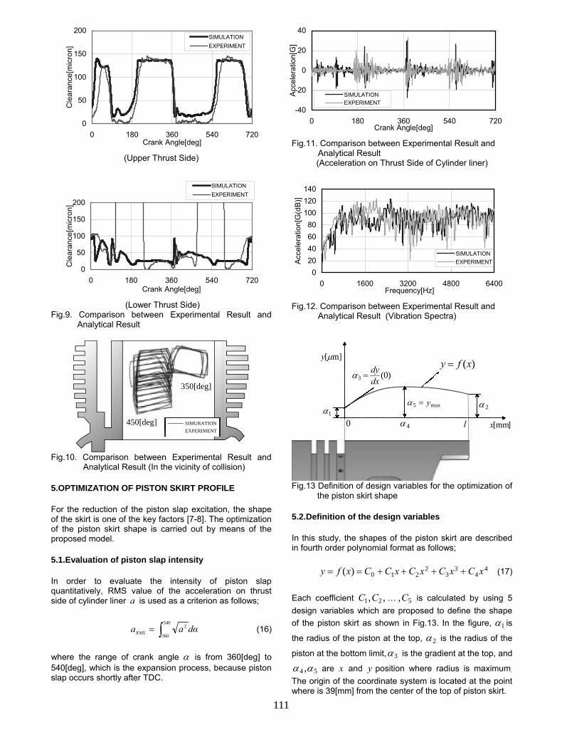
clearances between piston skirt and cylinder liner are compared with experimental results. The clearance at the thrust side is shown in Fig.9. Piston collides with the thrust side of cylinder liner three times in 720 degrees, and the strongest one occuers around 380[deg]. In Fig.10, there are jumps of signal around 180[deg] and 540[deg]. This is because the lower gap sensors get out from cylinder liner around BDC. However, as the strongest collision happens around TDC, they are negligible.
By comparing the number and the timing of the collision, simulation result corresponds with the experimental one in the whole area. The analytical model simulates the collision of the piston with cylinder liner quite well especially around TDC, where piston slap occurs.
The comparison of piston behavior is also carried out. The behavior of piston near TDC is shown in Fig.10. As shown in the figure, the timing of the collision, tilt of the piston and speed has sufficient agreement. From these results, the validity of the model is confirmed and it is verified that the model is efficient for the prediction of piston secondary motion.
The comparison of the vibration response on thrust side of cylinder liner is shown in Fig.11. As shown in the figure, the timing of the collision, the muximum level of the vibration response and the number of the collision correspond to each other very well. The spectra of them are also shown in Fig.12. From the result, the spectra match quite well in whole frequency range. From this result, the model of cylinder liner is also validated.
110
0
50
100
150
200
0 180 360 540 720Crank Angle[deg]
Cle
aran
ce[m
icro
n]
SIMULATIONEXPERIMENT
(Upper Thrust Side)
0
50
100
150
200
0 180 360 540 720Crank Angle[deg]
Cle
aran
ce[m
icro
n]
SIMULATIONEXPERIMENT
(Lower Thrust Side)
Fig.9. Comparison between Experimental Result and Analytical Result
350[deg]
450[deg]EXPERIMENTSIMURATION
Fig.10. Comparison between Experimental Result and
Analytical Result (In the vicinity of collision)
5.OPTIMIZATION OF PISTON SKIRT PROFILE
For the reduction of the piston slap excitation, the shape of the skirt is one of the key factors [7-8]. The optimization of the piston skirt shape is carried out by means of the proposed model.
5.1.Evaluation of piston slap intensity
In order to evaluate the intensity of piston slap quantitatively, RMS value of the acceleration on thrust side of cylinder liner a is used as a criterion as follows;
αdaaRMS ∫=540
360
2 (16)
where the range of crank angle α is from 360[deg] to 540[deg], which is the expansion process, because piston slap occurs shortly after TDC.
-40
-20
0
20
40
0 180 360 540 720Crank Angle[deg]
Acce
lera
tion[
G]
SIMULATIONEXPERIMENT
Fig.11. Comparison between Experimental Result and
Analytical Result (Acceleration on Thrust Side of Cylinder liner)
020406080
100120140
0 1600 3200 4800 6400Frequency[Hz]
Acce
lera
tion[
G(d
B)]
SIMULATIONEXPERIMENT
Fig.12. Comparison between Experimental Result and
Analytical Result (Vibration Spectra)
1α0 l
)0(3 dxdy=α
m][µy
]mm[x
2α
4α
)(xfy =
max5 y=α
Fig.13 Definition of design variables for the optimization of
the piston skirt shape
5.2.Definition of the design variables
In this study, the shapes of the piston skirt are described in fourth order polynomial format as follows;
44
33
2210)( xCxCxCxCCxfy ++++== (17)
Each coefficient ,, 21 CC … 5,C is calculated by using 5 design variables which are proposed to define the shape of the piston skirt as shown in Fig.13. In the figure, 1α is
the radius of the piston at the top, 2α is the radius of the
piston at the bottom limit, 3α is the gradient at the top, and
54 ,αα are x and y position where radius is maximum. The origin of the coordinate system is located at the point where is 39[mm] from the center of the top of piston skirt.
111
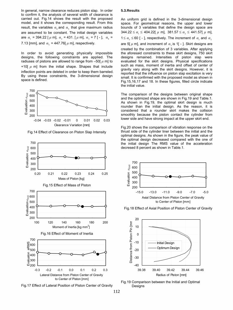
In general, narrow clearance reduces piston slap. In order to confirm it, the analysis of several width of clearance is carried out. Fig.14 shows the result with the proposed model, and it shows the corresponding result. From this result, the variables 4α and 5α that give maximum radius are assumed to be constant. The initial design variables are 1α = 394.22 [ µ m], 2α = 431. [ µ m], 3α = 7 [ - ], 4α = 7.13 [mm], and 5α = 447.76[ µ m], respectively.
In order to avoid generating physically impossible designs, the following constraints are applied. The radiuses of pistons are allowed to range from –50[ µ m] to +10[ µ m] from the initial shape. Shapes that include inflection points are deleted in order to keep them barreled. By using these constraints, the 3-dimensional design space is defined.
200300400500600700
-0.04 -0.03 -0.02 -0.01 0 0.01 0.02 0.03Clearance Variation [mm]
Eval
uatio
n a RMS
Fig.14 Effect of Clearance on Piston Slap Intensity
200300400500600700
0.20 0.21 0.22 0.23 0.24 0.25Mass of Piston [kg]
Eval
uatio
n a RMS
Fig.15 Effect of Mass of Piston
200300400500600700
100 120 140 160 180 200Moment of Inertia [kg mm2]
Eval
uatio
n aRMS
Fig.16 Effect of Moment of Inertia
200300400500600700
-0.3 -0.2 -0.1 0.0 0.1 0.2 0.3Lateral Distance from Piston Center of Gravity
to Center of Piston [mm]
Eval
uato
n a
RM
S
Fig.17 Effect of Lateral Position of Piston Center of Gravity
5.3.Results
An uniform grid is defined in the 3-dimensional design space. For geometrical reasons, the upper and lower bounds of 3 variables that define the design space are 344.22 ≤≤ 1α 404.22[ µ m], 381.57 ≤≤ 2α 441.57[ µ m], 1 ≤≤ 3α 60 [ - ], respectively. The increment of 1α and 2α are 5[ µ m], and increment of 3α is 1[ - ]. Skirt designs are created by the combination of 3 variables. After applying the aforesaid constraints to these skirt designs, 750 skirt designs remained. Intensities of piston slap were evaluated for the skirt designs. Physical specifications such as mass, moment of inertia and offset of center of gravity vary along with the skirt designs. However, it is reported that the influence on piston slap excitation is very small. It is confirmed with the proposed model as shown in Fig.15,16,17 and 18. In these figures, filled circle indicate the initial value.
The comparison of the designs between original shape and the optimized shape are shown in Fig.19 and Table.1. As shown in Fig.19, the optimal skirt design is much rounder than the initial design. As the reason, it is considered that a rounder skirt makes the collision smoothly because the piston contact the cylinder from lower side and have strong impact at the upper skirt end.
Fig.20 shows the comparison of vibration response on the thrust side of the cylinder liner between the initial and the optimal designs. As shown in the figure, the peak value of the optimal design decreased compared with the one of the initial design The RMS value of the acceleration decresed 8 percent as shown in Table.1.
200300400500600700
-15.0 -13.0 -11.0 -9.0 -7.0 -5.0Axial Distance from Piston Center of Gravity
to Center of Piston [mm]
Eval
uato
n aRMS
Fig.18 Effect of Axial Position of Piston Center of Gravity
-40
-30
-20
-10
0
10
20
39.38 39.40 39.42 39.44 39.46Radius of Piston [mm]
Dis
tanc
e fro
m P
isto
n Pi
n [m
m
Initial DesignOptimum Design
Fig.19 Comparison between the Initial and Optimal
Designs 112
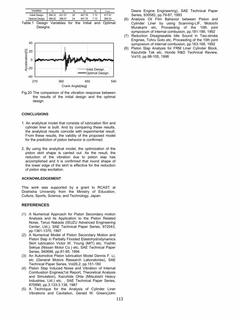
Variables α1 α2 α3 α4 α5 aRMSInitial Design 394.22 431.57 24 447.76 7.13 417.91
Optimal Design 389.22 396.57 24 447.76 7.13 384.53 Table.1 Design Variables for the Initial and Optimal
Designs
-40
-20
0
20
40
270 360 450 540Crank Angle[deg]
Acce
lera
tion[
G]
Inital DesignOptimal Design
Fig.20 The comparison of the vibration response between
the results of the initial design and the optimal design
CONCLUSIONS
1. An analytical model that consists of lubrication film and cylinder liner is built. And by comparing these results, the analytical results coincide with experimental result. From these results, the validity of the proposed model for the prediction of piston behavior is confirmed.
2. By using the analytical model, the optimization of the piston skirt shape is carried out. As the result, the reduction of the vibration due to piston slap has accomplished and it is confirmed that round shape of the lower edge of the skirt is effective for the reduction of piston slap excitation.
ACKNOWLEDGEMENT
This work was supported by a grant to RCAST at Doshisha University from the Ministry of Education, Culture, Sports, Science, and Technology, Japan.
REFERENCES
(1) A Numerical Approach for Piston Secondary motion Analysis and its Application to the Piston Related Noise, Teruo Nakada (ISUZU Advanced Engineering Center, Ltd.), SAE Technical Paper Series, 972043, pp.1361-1370, 1997
(2) A Numerical Model of Piston Secondary Motion and Piston Slap in Partially Flooded Elastohydrodynamics Skirt lubrication Victor W. Young (MIT) etc, Yoshiki Sekiya (Nissan Motor Co.) etc, SAE Technical Paper Series, 940696, pp.81-95, 1994
(3) An Automotive Piston lubrication Model Dennis F. Li, etc (General Motors Research Laboratories), SAE Technical Paper Series, Vol26,2, pp.151-160
(4) Piston Slap Induced Noise and Vibration of Internal Combustion Engines(1st Report, Theoretical Analysis and Simulation), Kazuhide Ohta (Mitsubishi Heavy Industries, Ltd.) etc. , SAE Technical Paper Series, 870990, pp.3.133-3.138, 1987
(5) A Technique for the Analysis of Cylinder Liner Vibrations and Cavitation, Gerald W. Green(John
Deere Engine Engineering), SAE Technical Paper Series, 930582, pp.79-87, 1993
(6) Analysis Oil Film Bahavior between Piston and Cylinder Liner by using Scanning-LIF, Motoichi Murakami etc, Proceeding of the 10th joint symposium of internal combusion, pp.181-186, 1992
(7) Reduction Disagreeable Idle Sound in Two-stroke Engines, Tohru Goto etc, Proceeding of the 10th joint symposium of internal combusion, pp.163-168, 1992
(8) Piston Slap Analysis for FRM Liner Cylinder Block, Kazuhide Tak etc, Honde R&D Technical Review, Vol10, pp.98-105, 1998
113