ReadMe First 概要解説書 - FDT Jfdt-j.co.jp/tech-info-pdf/StarterKit/Readme_First...
23
Copyright © 2015 FLAT Display Technology Corporation. All rights reserved. Add: No.85, Sec. 1, Fuxing Rd., South Dist., Taichung City 402, Taiwan (R.O.C.) http:// www.fdt.com.tw E-mail: [email protected] Tel: 886-4-22619577, Fax: 886-4-22623978 ReadMe First 概要解説書 概要解説書 概要解説書 概要解説書 Version:1.3 Date:October 19 , 2015
Transcript of ReadMe First 概要解説書 - FDT Jfdt-j.co.jp/tech-info-pdf/StarterKit/Readme_First...

Copyright © 2015 FLAT Display Technology Corporation. All rights reserved. Add: No.85, Sec. 1, Fuxing Rd., South Dist., Taichung City 402, Taiwan (R.O.C.) http:// www.fdt.com.tw E-mail: [email protected]
Tel: 886-4-22619577, Fax: 886-4-22623978
ReadMe First
概要解説書概要解説書概要解説書概要解説書
Version ::::1.3
Date::::October 19 , 2015

2015 10 19 V1.3 ReadMe First
P.1 Copyright © 2015 FDT http:// www.fdt.com.tw, E-mail- [email protected]
This technical specification is subject to change without notice
第1章第1章第1章第1章 SGM (Smart Graphic Module Plus) の紹介の紹介の紹介の紹介 Start Kit .................... 2
1.1 まえがきまえがきまえがきまえがき ............................................................................................................ 2
1.2 P/N of Start Kit の型番の型番の型番の型番 ...................................................................................... 2
1.3 Packaging List ................................ .................................................................. 3
1.4 SGM Plus CD の詳細内容の詳細内容の詳細内容の詳細内容 ................................................................................. 6
第2章第2章第2章第2章 Start Kit の動作モードの動作モードの動作モードの動作モード ..................................................................... 7
2.1 Auto Mode ..................................... .................................................................... 7
2.2 UART Mode. .................................... .................................................................. 8
2.3 MCU Mode ...................................... ................................................................. 10
第3章第3章第3章第3章 SGM Plus の開発プロセスの開発プロセスの開発プロセスの開発プロセス ............................................................ 11
3.1 SGM Plus 開発プロセス開発プロセス開発プロセス開発プロセス ................................................................................. 11
第4章第4章第4章第4章 Basic/ Advanced 開発資料開発資料開発資料開発資料 .......................................................... 15
4.1 Basic Development Items ....................... ....................................................... 15
4.2 Advanced Development Items .................... .................................................. 16
Appendix A: Profile 更新の方法更新の方法更新の方法更新の方法 (SGM_Plus.BIN) 7" module を参照を参照を参照を参照 ........... 17
Contents

2015 10 19 V1.3 ReadMe First
P.2 Copyright © 2015 FDT http:// www.fdt.com.tw, E-mail- [email protected]
This technical specification is subject to change without notice
第1章第1章第1章第1章 SGM (Smart Graphic Module Plus) Start Kit の紹介の紹介の紹介の紹介
1.1 まえがきまえがきまえがきまえがき
ユーザーがこのReadMe Firstをご覧になると次のことが容易に理解できます。
1. Start Kitに含まれるAccessories類, operation manuals, application and guidance to examples.
2. Start KitによりSGM PLUSの動作デモを簡単に体験できます。
3. 開発に必要なツールやマニュアルのデモンストレーション
4. 第4章で紹介する Operation Manuals and Introductions を参照して説明。
5. 複数のデモサンプルがユーザーの開発ヒントとなると確信します。
1.2 Start Kit の種類と型番の種類と型番の種類と型番の種類と型番
Size (Res.) Start Kit P/N Standard Module P/N
3.5”(320x234) FPEP035QA4-00R FP035QIA14-00R
4.3”(480*272) FPEP043YA4-00R FP043YIA14-00R
5.6” (640x480) FPEP056VA4-00R FP056VIA04-00R
7” (800x480) FPEP070WA4-00R FP070WIA04-00R
10.4”(800x600) FPEP104SA4-00R FP104SIA24-00R

2015 10 19 V1.3 ReadMe First
P.3 Copyright © 2015 FDT http:// www.fdt.com.tw, E-mail- [email protected]
This technical specification is subject to change without notice
CDの中にある仕様書を参照ください。の中にある仕様書を参照ください。の中にある仕様書を参照ください。の中にある仕様書を参照ください。
Path File Name
CD:\Specifications\ FP035QIA1x-00R\ FP035QIA1x-00R.pdf
CD:\Specifications\ FP043YIA1x-00R\ FP043YIA1x-00R.pdf
CD:\Specifications\ FP056VIA0x-00R\ FP056VIA0x-00R.pdf
CD:\Specifications\ FP070WIA0x-00R\ FP070WIA0x-00R.pdf
CD:\Specifications\ FP104SIA2x-00R\ FP104SIA2x-00R.pdf
1.3 Packaging List
NO Item Order P/N Picture Note
1 Graphic Control Kit
(GCK-003) LOMCU0003B- FDR
2 SGM Plus 5V Input + RS232 to
UART LOPOWER011-FDR
3
USB To UART Converter Board
LOUSB00001-FDR
4
Power Cord for Europe
(L:1800mm)
(shipping depend on Area)
LACABLE047-FDR
5
Power Cord for USA
(L:1800mm)
(shipping depend on Area)
LAAC818000-FDR

2015 10 19 V1.3 ReadMe First
P.4 Copyright © 2015 FDT http:// www.fdt.com.tw, E-mail- [email protected]
This technical specification is subject to change without notice
6 L:1500mm,100-240VAC 47-63Hz
to +5VDC @ 3A,ψ2.5 LASTD05030-FDR
7 USB Extended Cable (A-Type Plug
_A-Type Receptacle L:1800mm) LAUSB18001-FDR
8
RS232 Cable Female/Female
Null Modem type L:1800mm
(white)
LACABLE045-FDR
9
Power & UART Cable 7Pin 2.0mm
to DC Jack+4Pin 1.25mm
(L:150mm)
LACABLE008- FDR
for
4.3”~10.4”
10
Power & UART Cable 5Pin
1.25mm to DC Jack+4Pin 1.25mm
(L:150mm)
LACABLE012-FDR
for 3.5”
only
11 GCK-003 Signal Cable 7Pin 2.0mm
to 7Pin 1.25mm (L:150mm) LACABLE009- FDR
for
4.3”~10.4”
12 CK-003 Signal Cable 5Pin 1.25mm
to 7Pin 1.25mm (L:150mm) LACABLE016-FDR
for 3.5”
only
13 Cable 5Pin 1.25mm to 4Pin
1.25mm(L:120mm) LACABLE010-FDR
14 Micro SDHC 4GB LASDCD0001-FDR
15 PIN HEADER 2.0mm 2P Jumper
(Black) LACONN0016-FDR

2015 10 19 V1.3 ReadMe First
P.5 Copyright © 2015 FDT http:// www.fdt.com.tw, E-mail- [email protected]
This technical specification is subject to change without notice
16
Micro SD to USB adapter
LASDCD0003-FDR
17 CR1220 Li-ion Battery(3V) LABATT0001-FDR
18 DVD-ROM Disk LADVD00003- FDR

2015 10 19 V1.3 ReadMe First
P.6 Copyright © 2015 FDT http:// www.fdt.com.tw, E-mail- [email protected]
This technical specification is subject to change without notice
1.4 Index in CD of SGM Plus

2015 10 19 V1.3 ReadMe First
P.7 Copyright © 2015 FDT http:// www.fdt.com.tw, E-mail- [email protected]
This technical specification is subject to change without notice
第2章第2章第2章第2章 Start Kit の評価の評価の評価の評価
Start Kit の default demonstration mode は Auto, UART および MCU mode があります。
詳細は次を参照ください。詳細は次を参照ください。詳細は次を参照ください。詳細は次を参照ください。 ”CD: \Start Kit\Documents\Start_Kit_Demo_User_Guide.pdf ”
2.1 Auto Mode Auto Mode に入ると ICON での各種 demo を体験できます。
Step1:Please refer to ’CD:\ SGM_Plus_Quick_Start.pdf’ for assembling details.
Boot Screen is as below.
Step2:Click “Auto” to enter AUTO MODE.
Step3:ICON をクリックすると割当てられた機能 demo をみることができます。

2015 10 19 V1.3 ReadMe First
P.8 Copyright © 2015 FDT http:// www.fdt.com.tw, E-mail- [email protected]
This technical specification is subject to change without notice
2.2 UART Mode Pre-install された ”StartKit_Demo_xxx.txt” を使って次の接続モードの機能をデモ体験できます。
USB- to-UART-Converter-Board の接続および PC で CommandPilot2 を使用してのデモ。
詳細資料:詳細資料:詳細資料:詳細資料: ”CD: \Start Kit\Documents\Start_Kit_Demo_User_Guide.pdf” for details.
Step1:アッセンブリに際しての詳細は ’CD:\ SGM_Plus_Quick_Start.pdf’ をご覧ください。
起動画面は次のとおりです。
Step2:Click UART to enter the page below.
Step3:Command_Pilot2 に ”StartKit_Demo_xxx.txt” を import するとデモを体験できます。

2015 10 19 V1.3 ReadMe First
P.9 Copyright © 2015 FDT http:// www.fdt.com.tw, E-mail- [email protected]
This technical specification is subject to change without notice
関連ツール 2-2-1
Items Path File Name Remarks
Command
Pilot2 Operation Guide
CD:\ Tools(software)
\FDT-Command_pilot2 Command_Pilot2_Operation_Guide.pdf Read this first.
SGM Plus
UART Command Manual
CD:\ Tools(software)
\ FDT-Command_pilot2\ SGM_Plus_UART_Command_Manual.pdf
USB to UART Converter
Installation Guide
CD: \ Tools(software)\ USB to
UART Converter Driver\
USB_to_UART_Converter_Installation
_Guide.pdf
USB to UART Converter
Driver
CD: \ Tools(software)
\ USB to UART Converter Driver
\CDM v2.08.30 WHQL Certified\
-
Command_Pilot2 CD:\ Tools(software)
\ FDT-Command_pilot2\ FDT-Command_pilot2(2.6.10.1)
Command_Pilot2
demo examples
CD:\Start Kit
\UART Example\Demo StartKit_Demo_xxx.txt 15 items in total

2015 10 19 V1.3 ReadMe First
P.10 Copyright © 2015 FDT http:// www.fdt.com.tw, E-mail- [email protected]
This technical specification is subject to change without notice
2.3 MCU Mode MCU controller board (GCK-003)を経由した preinstall サンプルのデモ
詳細は詳細は詳細は詳細は ”CD: \Start Kit\Documents\Start_Kit_Demo_User_Guide.pdf ” を参照を参照を参照を参照
Step1:アッセンブリに際して詳細は’CD:\ SGM_Plus_Quick_Start.pdf’ を参照ください。
起動画面は次のとおりです。
Step2:Press buttons on GCK-003 to run demo examples.
Previo
Next
Run

2015 10 19 V1.3 ReadMe First
P.11 Copyright © 2015 FDT http:// www.fdt.com.tw, E-mail- [email protected]
This technical specification is subject to change without notice
第3章第3章第3章第3章 SGM Plus Development Process
3.1 SGM Plus 開発の手順開発の手順開発の手順開発の手順
Item Tools Flow Chart Note
1
1.PC + Windows 7/8
2.FDT Arranger Plus
3.Photo Shop/Illustrator
Remarks 3-1
2 1.Windows 7/8 PC
2.Photo Shop/Illustrator
PNG format
is recommended.
3
1.Windows 7/8 PC
2.FDT Arranger Plus
3.BMP/PNG images
4.Build Font
Remarks 3-1
4 1.Windows 7/8 PC
2.FDT Arranger Plus
Remarks 3-1
Note1
5
1. Windows 7/8 PC
2. FDT Arranger Plus
3. SGM Plus TFT Module
4. Micro SD Card
Remarks 3-1
Appendix A
How to update profile
6
1. SGM Plus Module
2. 2.GCK-003
Remarks 3-2
How to connect each
part in SGM PLUS.
7
Program Compiler
1.KEIL C FOR GCK-003
3. User-Defined
MCU Board can be
FDT’s GCK-003
Board or users’
device.
Restore profile (SGM_Plus.BIN)
from Arranger to Micro SD Card
and then update to SGM Plus
Build user-defined GUI profile
(xxx.ar2) and configure MACRO.
Set up SGM Plus &
MCU (GCK-003)
Program & debug at users.
+
Process images/ icons required
in users’ projects.
1. Import images/icons into Arranger+
2. Generate art words or fonts via
Arranger+
A
B
+ Or

2015 10 19 V1.3 ReadMe First
P.12 Copyright © 2015 FDT http:// www.fdt.com.tw, E-mail- [email protected]
This technical specification is subject to change without notice
Item Tools Flow Chart Note
8
1.Windows 7/8 PC
2.GCK-003
3. USB to UART
Converter
4.GCK-003 update
program
5.UartISP_v3.0.0.exe
Remarks 3-3
GCK-003 Reference
9 1.SGM Plus Module
2.GCK-003
10
1.SGM Plus 7' Module
2.GCK-003
3.PC Windows 7/8
4.FDT Arranger Plus
11
Remarks 3-1 参考資料参考資料参考資料参考資料
Item Path File name Note
Arranger Plus Installation
Guide
CD:\
\Tools(software)\Arranger
Plus\English\
Arranger_Plus_Installation_Guide.pdf
Arranger Plus Simple
Operation Guide
CD:\
\Tools(software)\Arranger
Plus\English\
Arranger_Plus_Simple_Operation_Guide.pdf
この資料を最初
にお読みくださ
い。
Arranger Plus User Manual
CD:\
\Tools(software)\Arranger
Plus\English\
Arranger_Plus_User_Manual.pdf
Note1. “xxx.AR2” is the file names created by Arranger+ for different GUI projects.
Finish
Update programs in FDT’S
GCK-003 board or Users’
MCU Board.
A
B
Verify if
MCU works?
Verify if the profile
from Arranger+
works fine?
Yes
No
Yes
No

2015 10 19 V1.3 ReadMe First
P.13 Copyright © 2015 FDT http:// www.fdt.com.tw, E-mail- [email protected]
This technical specification is subject to change without notice
Remarks 3-2: GCK-003 とととと SGM PLUS の附属部品の接続方法の附属部品の接続方法の附属部品の接続方法の附属部品の接続方法
1. 7" SGM PLUS と GCK-003 との接続を例に説明します(4.3"/5.6"/10.4" SGM PLUS も同様)
2. Connection between3.5" SGM PLUS and GCK-003
GCK-003
5V Adapter Plug
7Pin 1.25mm 7Pin 2.0mm
GCK-003 Signal Cable
Power ON/OFF
UART Transmission
Refer to command list
CD:\ Tools(software)\
FDT-Command_pilot2\
SGM_Plus_UART_Command_Manual.pdf
GCK-003
GCK-003 Signal Cable
5Pin 1.25mm
7Pin 1.25mm
Power SW
UART Transmission

2015 10 19 V1.3 ReadMe First
P.14 Copyright © 2015 FDT http:// www.fdt.com.tw, E-mail- [email protected]
This technical specification is subject to change without notice
Remarks 3-3 ::::GCK-003 Reference
Item Path File Name Note
GCK-003 Programming
Operation Guide.
CD:\Start Kit\GCK-003
Tools\GCK-003 FW GCK-003_Programming_Operation_Guide.pdf
Graphic Control Kit
(GCK-003) Diagram
CD: \Start Kit\GCK-003
Tools\GCK-003 Circuit GCK-003_Circuit_v1.2C.pdf
MCU data of Graphic
Control Kit (GCK-003)
CD:\ StartKit\
GCK-003_Tools\ WT61P9
Datasheet\
WT61P9.pdf
GCK-003 Example Source
codes
CD: \Start Kit\GCK-003
Tools\GCK-003 FW\Source
Code\Demo
- 16 items.
Update Tools (Execution
files)
CD: \Start Kit\GCK-003
Tools\UartISP UartISP_v3.0.0.exe

2015 10 19 V1.3 ReadMe First
P.15 Copyright © 2015 FDT http:// www.fdt.com.tw, E-mail- [email protected]
This technical specification is subject to change without notice
第4章第4章第4章第4章 基本的開発の資料および上級開発の資料基本的開発の資料および上級開発の資料基本的開発の資料および上級開発の資料基本的開発の資料および上級開発の資料
4.1 基本的開発の資料基本的開発の資料基本的開発の資料基本的開発の資料

2015 10 19 V1.3 ReadMe First
P.16 Copyright © 2015 FDT http:// www.fdt.com.tw, E-mail- [email protected]
This technical specification is subject to change without notice
4.2 上級開発の資料上級開発の資料上級開発の資料上級開発の資料
2015 10 19 V1.3 ReadMe First
P.17 Copyright © 2015 FDT http:// www.fdt.com.tw, E-mail- [email protected]
This technical specification is subject to change without notice
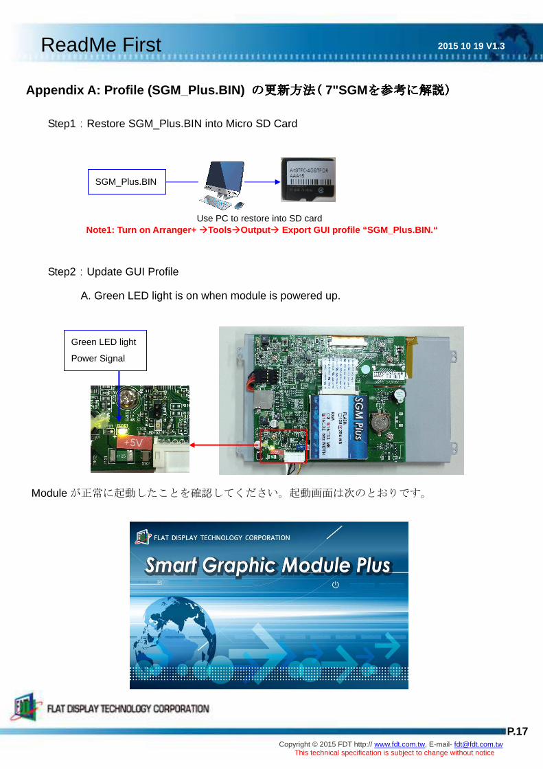
Appendix A: Profile (SGM_Plus.BIN) の更新方法の更新方法の更新方法の更新方法(((( 7"SGMを参考に解説を参考に解説を参考に解説を参考に解説))))
Step1:Restore SGM_Plus.BIN into Micro SD Card
Note1: Turn on Arranger+ �Tools�Output� Export GUI profile “SGM_Plus.BIN.“
Step2:Update GUI Profile
A. Green LED light is on when module is powered up.
Module が正常に起動したことを確認してください。起動画面は次のとおりです。
SGM_Plus.BIN
Use PC to restore into SD card
Green LED light
Power Signal

2015 10 19 V1.3 ReadMe First
P.18 Copyright © 2015 FDT http:// www.fdt.com.tw, E-mail- [email protected]
This technical specification is subject to change without notice
C. Micro SD Card を SD slot に差すとすぐに update が始まります。
Step3:update が完了すると ”Update finished” と表示されます。
Step4:Micro SD Card を取り出し再度 SGM+ に電源を入れます。GUI profile が画面に表示さ
れます。 下図は画面の例です。
Note: Micro SD Card の取り出しを忘れた場合はの取り出しを忘れた場合はの取り出しを忘れた場合はの取り出しを忘れた場合は SD card を再挿入した時やを再挿入した時やを再挿入した時やを再挿入した時や modulemodulemodulemodule に電源を入れた時にに電源を入れた時にに電源を入れた時にに電源を入れた時に GUI
profile のののの update が強制的に始まります。が強制的に始まります。が強制的に始まります。が強制的に始まります。
Red LED light
Flickering:Updating
On:Finished
Micro SD Slot

2015 10 19 V1.3 ReadMe First
P.19 Copyright © 2015 FDT http:// www.fdt.com.tw, E-mail- [email protected]
This technical specification is subject to change without notice
Other sizes
P/N Description
FPEP035QA4-00R FP035QIA14-00R
Green LED light
Power Signal Micro SD Slot
Red LED light
Flickering:
Updating

2015 10 19 V1.3 ReadMe First
P.20 Copyright © 2015 FDT http:// www.fdt.com.tw, E-mail- [email protected]
This technical specification is subject to change without notice
FPEP043YA4-00R FP043YIA14-00R
P/N Description
PEP056VA4-00R
FP056VIA04-00R
Red LED light
Flickering:
Updating
Green LED light
Power Signal
Micro SD Slot
Green LED light
Power Signal
Red LED light
Flickering:
Updating
Micro SD Slot

2015 10 19 V1.3 ReadMe First
P.21 Copyright © 2015 FDT http:// www.fdt.com.tw, E-mail- [email protected]
This technical specification is subject to change without notice
FPEP104SA4-00R
FP104SIA24-00R
Micro SD Slot
Red LED light
Flickering:
Updating
Green LED light
Power Signal

2015 10 19 V1.3 ReadMe First
P.22 Copyright © 2015 FDT http:// www.fdt.com.tw, E-mail- [email protected]
This technical specification is subject to change without notice
第5章第5章第5章第5章 改訂履歴改訂履歴改訂履歴改訂履歴
5.1 改訂記録改訂記録改訂記録改訂記録
NO. Date Description Page Note
1.0 July 13, 2015 .First draft 19
1.1 August 12, 2015 .Additional parts 5~6
1.2 September 16,2015 .Update1.4 Index in CD of SGM Plus 6
1.3 October 19,2015 .Update1.4 Index in CD of SGM Plus 6
5.2 內內內內內內內內內內內內內內內內
NO. Date Description Page Note
0.0 May 4, 2015 .First draft (Tentative) 16
0.0 May 21, 2015 .1.3 Packaging List2 光光光光 4
.Step4:修修修修 13
0.0 June 15,2015 .1.2 新新 5.6&10.4模模模模模模光光 2
0.0 July 10,2015 .1.2新新 3.5&4.3模模模模模模光光 2
.1.3 新新 3.5&4.3配配 3~4
.加加 3.5與GCK連連連連連 12
.連連 3-2:如如如新配如連如如加修修如如如如 A 16~17
.加加 3.5、4.3、5.6、10.4連圖連連 18~19
1.1 August 12,2015 .Additional parts 5~6
.UART 傳傳修傳UART Transmission 13
1.2 September 16,2015 .Update1.4 Index in CD of SGM Plus 6
1.3 October 19,2015 .Update1.4 Index in CD of SGM Plus
(新加Demo 專專專專) 6