RADIO CONTROL SYSTEM - tme.eu · SN PROMET 41-200 Sosnowiec ul. Lipowa 11 IO-KR-01 (10.2017r) Page:...
13
SN PROMET 41-200 Sosnowiec ul. Lipowa 11 IO-KR-01 (10.2017r) Page: 1/13 RADIO CONTROL SYSTEM Instruction Manual Spółdzielnia Niewidomych PROMET Tel.: 032 26 98 100, Fax: 032 26 98 128 Customer Service tel.:887 552 100, 887 552 200 e-mail: [email protected] Marketing Department tel.:032 26 98 193,032 26 98 195 fax: 032 2698128,e-mail: marketing@sn- promet.com.pl
Transcript of RADIO CONTROL SYSTEM - tme.eu · SN PROMET 41-200 Sosnowiec ul. Lipowa 11 IO-KR-01 (10.2017r) Page:...

SN PROMET
41-200 Sosnowiec
ul. Lipowa 11
IO-KR-01 (10.2017r)
Page: 1/13
RADIO CONTROL SYSTEM
Instruction Manual
Spółdzielnia Niewidomych
PROMET Tel.: 032 26 98 100,
Fax: 032 26 98 128
Customer Service tel.:887 552 100, 887 552
200 e-mail: [email protected]
Marketing Department tel.:032 26 98 193,032 26 98
195 fax: 032 2698128,e-mail: marketing@sn-
promet.com.pl
SN PROMET
41-200 Sosnowiec
ul. Lipowa 11
IO-KR-01 (10.2017r)
Page: 2/13
Table of contents I Intended use ........................................................................................................................................................... 3
II Technical data ........................................................................................................................................................ 3
1. Joint parameters ......................................................................................................................................................... 3
2. Transmitter ................................................................................................................................................................ 3
3. Receiver ..................................................................................................................................................................... 3
III Design and principle of operation .......................................................................................................................... 4
1. Transmitter ................................................................................................................................................................ 4
1.1. Pairing mode .......................................................................................................................................................... 4
1.2. Normal operation mode.......................................................................................................................................... 6
2. Receiver ..................................................................................................................................................................... 7
3. Overall dimensions .................................................................................................................................................. 11
4. User precautions ...................................................................................................................................................... 11
5. Fitter precautions ..................................................................................................................................................... 12
6. Maintenance ............................................................................................................................................................ 12
6.1. Daily maintenance ................................................................................................................................................ 12
6.2. Periodic maintenance – every 3 months ............................................................................................................... 13
6.3. Periodic maintenance – every 6 months ............................................................................................................... 13
IV Appendices ........................................................................................................................................................... 13
1. Protection of the environment – utilisation of waste electronic equipment ............................................................. 13
2. Scheme of assembly holes drilling .......................................................................................................................... 13

SN PROMET
41-200 Sosnowiec
ul. Lipowa 11
IO-KR-01 (10.2017r)
Page: 3/13
I Intended use
The radio control system is equipment for wireless machine control. It consists of a transmitter and a receiver.
The equipment is available in two voltage options . i.e. 230VAC and 24-48VAC.
The receiver operates at radio waves for transferring machine instructions, which catches all commands to be
executed by a machine. If the radio transmission is interrupted, incorrect or false, the receiver will automatically stop
the entire system.
Please read this instruction manual and be sure to follow its recommendations.
II Technical data
1. Joint parameters
Operating frequency .................................................................................................. ……………….ISM 434MHz
Number of channels ................................................................................................... …………………………...63
Transmission power ................................................................................................... ………………………10mW
Typical range ............................................................................................................. ………………………..50m*
Maximum range ......................................................................................................... ………………..80m/150m**
Degree of protection IP ............................................................................................. …………………………...65
2. Transmitter
Supply voltage Un ..................................................................................................... ……………………….2 - 3V
Minimum battery life ................................................................................................. ……………….about 20h***
Maximum power consumption during normal operation .......................................... ……………………110mA
Battery power consumption when switched off ......................................................... …………………50μA****
Ambient temperature during operation ...................................................................... ……………….-20°C ÷ 55°C
Storage temperature ................................................................................................... ………………..40°C ÷ 70°C
Dimensions ................................................................................................................ …………….215X65X50mm
Weight ....................................................................................................................... ………………….about 350g
3. Receiver
Supply for the 230V option:
Supply voltage Uz.......................................................................................................................................................... ……………………….100-240V AC
Maximum supply current Imax ............................................................................................................................. ………………………………………0,2A
Supply for the 48V option:
Supply voltage Uz........................................................................................................................................................................... ………………..18-60V AC
Maximum supply current Imax .............................................................................................................................................. ……………………………...1A
Rated current (power) of safety relay contact load in category:
AC1: ..................................................................................................................................... …….…6A/250VAC
AC15: ................................................................................................................................... ……………….…3A
DC13: ................................................................................................................................... ………………….6A
Rated current (power) of function relay contact load in category:
AC1: ..................................................................................................................................... ………...5A/250VAC
10A/125VAC
AC1: ..................................................................................................................................... …………….1250 VA

SN PROMET
41-200 Sosnowiec
ul. Lipowa 11
IO-KR-01 (10.2017r)
Page: 4/13
AC3: ....................................................................................................................... …..186W (single-phase motor)
DC1: .......................................................................................................................... …………………5A/28VDC
Cable section ............................................................................................................. ……………….0.2--2.5 mm2
Safety relay mechanical durability ............................................................................ …………………..107 cycles
Function relay mechanical durability ........................................................................ …………………..107 cycles
Ambient temperature during operation ...................................................................... ……………….-20°C ÷ 55°C
Storage temperature ................................................................................................... ……………….-40°C ÷ 70°C
Dimensions ................................................................................................................ …………….225x175x80mm
Cable gland ................................................................................................................ ………………………..PG21
Weight ....................................................................................................................... …………………..about 1 kg
*- the range depends on the surrounding conditions and may differ from the specified value
**- with the external antennae, the range depends on the surrounding conditions and may differ from
the specified value
*** approximate time for the remote control supply with two NiMH AA batteries with 2000mAh
capacity each
**** - with the “Emergency STOP” button switched on and after 2 minutes of inactivity
III Design and principle of operation
The radio control system consists of a transmitter and a receiver.
1. Transmitter
The transmitter should be powered by two NiMH storage cells or two NiMH alkaline AA batteries. The keyboard
consists of 10 buttons, of which 8 are two-level ones, that is, with two release thresholds, and two with one release
threshold. The key scheme is presented on figure 1.
Additionally, the transmitter is featured with a “STOP” emergency button, which main function is blocking the control
possibility in case of emergency.
1.1. Pairing mode
The transmitter-receiver set must be paired for proper operation. The set is paired by default by the manufacturer. If the
transmitter or receiver set is replaced, it is essential to re-pair the devices. Pairing is carried out in a special pairing mode.
The pairing mode activation procedure:
1. Switch on the receiver.
2. Switch on the transmitter by briefly pressing any button.
3. Switch the “Emergency STOP” button.
4. Press the S3 button fully.
5. Holding the S3 button, press the “Emergency STOP” button.
6. The transmitter enters the pairing mode which is indicated by pulsating red light on the D5 LED.
7. The transmitter is in the pairing mode until the devices are paired correctly, but not longer than 2 minutes.
8. After the devices are paired successfully, the transmitter enters the normal operation mode.
9. If pairing is failed, the transmitter is switched off.

SN PROMET
41-200 Sosnowiec
ul. Lipowa 11
IO-KR-01 (10.2017r)
Page: 5/13
Emergency button
D1 LED
D3 LED
D2 LED
D4 LED
D5 LED
S2 control
function button S1 control
function button
S4 control
function button S3 control
function button Battery
cover
Battery
cover
bolts
S6 control
function button S5 control
function button
S8 defined
function button S7 defined
function button
S10
Start/Buzzer
button
S9 hoist
selection
button
Lead/belt
holder
Plate with
serial
number
Battery
chamber
Figure 1
SN PROMET
41-200 Sosnowiec
ul. Lipowa 11
IO-KR-01 (10.2017r)
Page: 6/13
1.2. Normal operation mode
The RCT_01 radio control transmitter is featured with four basic operation functions:
Switching on/off the transmitter.
In order to switch on the transmitter, unblock the “Emergency STOP” button. The transmitter is switched on
by pressing any button. After switching on, the transmitter is automatically connected with the receiver. The
remote control is switched off after 2 minutes of inactivity (2 minutes after the last button press on the
keyboard).
Transmitter authorisations.
The transmitter authorisations (unblocking the possibility of receiver outputs control) are activated by pressing
the S10 key for at least 2s. After activating authorisations with use of the remote control, the receiver switches
on the “Emergency STOP” circuit relays and switches on the K19 relay until the S10 button is released
(terminals no. 37, 38 - intended for the sound signalling device).
Control via transmitter.
After switching on and activating the transmitter authorisations you may proceed to control procedure. Any
button press results in switching on a corresponding relay in the receiver (the description of transmitter buttons
and relay contacts assigned to them is presented in table 3).
Emergency control switch-off.
Emergency switch-off of the radio control system is done by pressing the “Emergency STOP” button.
The press of the button results in opening the “Emergency STOP” relay circuits in the receiver and switching
off all function relays in the receiver. The switch-on of the “Emergency STOP” button results also in blocking
the transmitter - it does not react to any function buttons.
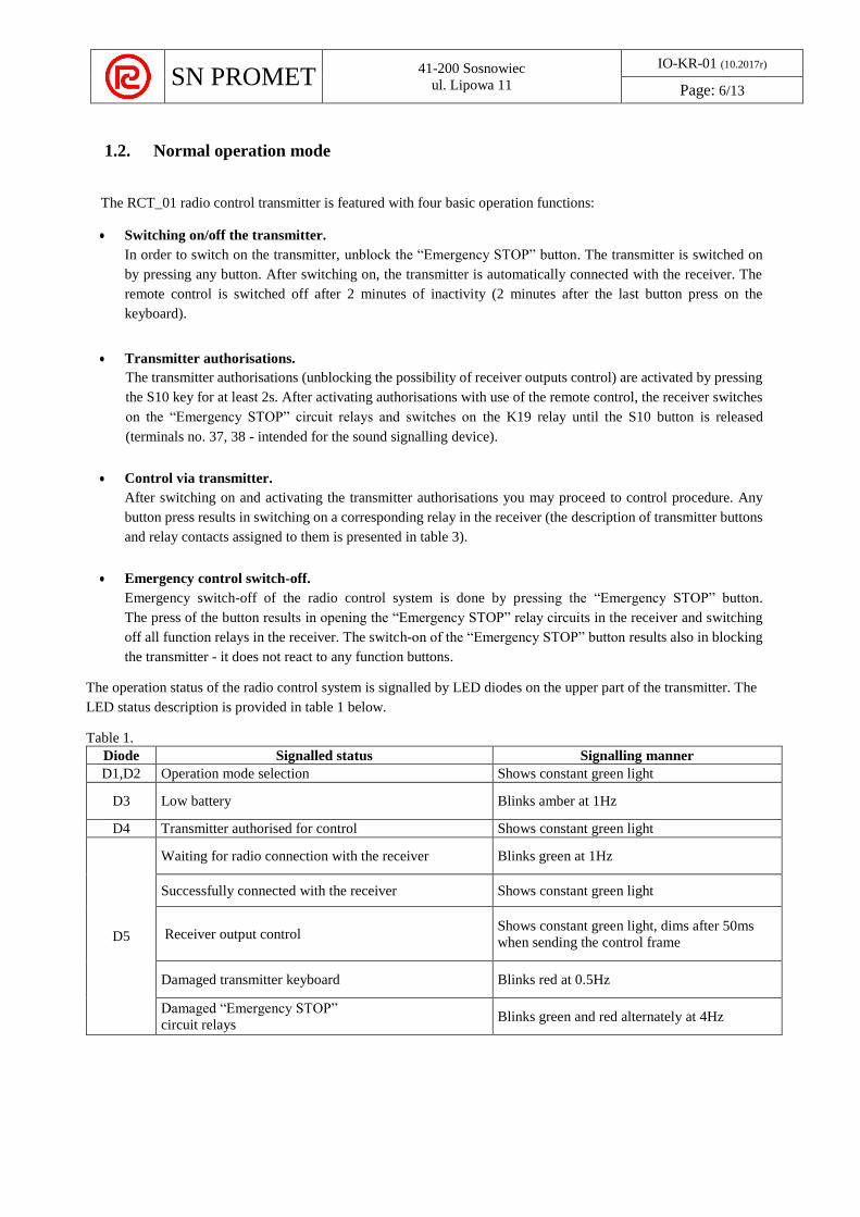
The operation status of the radio control system is signalled by LED diodes on the upper part of the transmitter. The
LED status description is provided in table 1 below.
Table 1.
Diode Signalled status Signalling manner
D1,D2 Operation mode selection Shows constant green light
D3 Low battery Blinks amber at 1Hz
D4 Transmitter authorised for control Shows constant green light
D5
Waiting for radio connection with the receiver Blinks green at 1Hz
Successfully connected with the receiver Shows constant green light
Receiver output control Shows constant green light, dims after 50ms
when sending the control frame
Damaged transmitter keyboard Blinks red at 0.5Hz
Damaged “Emergency STOP”
circuit relays Blinks green and red alternately at 4Hz
SN PROMET
41-200 Sosnowiec
ul. Lipowa 11
IO-KR-01 (10.2017r)
Page: 7/13
2. Receiver
The ERC01_RCR_01 receiver consists of the following function circuits:
a radio module,
a control unit,
function execution circuits,
“Emergency STOP” circuits,
a power supply unit.
The general receiver operation rule is as follows: the radio module, having received the information from the remote
control, sends it to the control unit, which, having checked the information correctness, switches on the execution
circuit relay, it is implemented for the command received from the transmitter.
The central unit controls the “Emergency STOP” circuit - should it not receive an appropriate command from the
remote control, the “Emergency STOP” circuit and execution relays remain safe, that is, switched off. There are two
situations, when the “Emergency STOP” circuit may be disconnected:
If the connection with the remote control is broken, the “Emergency STOP” circuit is automatically
disconnected.
Press of the “Emergency STOP” button on the remote control.
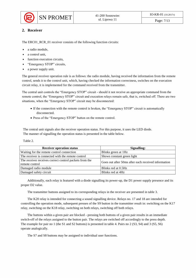
The central unit signals also the receiver operation status. For this purpose, it uses the LED diode.
The manner of signalling the operation status is presented in the table below.
Table 2.
Receiver operation status Signalling:
Waiting for the remote control connection Blinks green at 1Hz
The receiver is connected with the remote control Shows constant green light
The receiver receives correct control packets from the
remote control Goes out after 50ms after each received information
Damaged radio module Blinks red at 0.5Hz
Damaged safety circuit Blinks red at 4Hz
Additionally, each relay is featured with a diode signalling its power-up, the D1 power supply presence and its
proper D2 value.
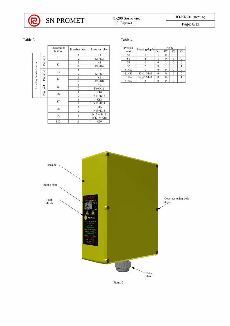
The transmitter buttons assigned to its corresponding relays in the receiver are presented in table 3.
The K20 relay is intended for connecting a sound signalling device. Relays no. 17 and 18 are intended for
controlling the operation mode, subsequent presses of the S9 button in the transmitter result in: switching on the K17
relay, switching on the K18 relay, switching on both relays, switching off both relays.
The buttons within a given pair are blocked - pressing both buttons of a given pair results in an immediate
switch-off of the relays assigned to the button pair. The relays are switched off accordingly to the press depth.
The example for pair no 1 (the S1 and S2 buttons) is presented in table 4. Pairs no 2 (S3, S4) and 3 (S5, S6)
operate analogically.
The S7 and S8 buttons may be assigned to individual user functions.
SN PROMET
41-200 Sosnowiec
ul. Lipowa 11
IO-KR-01 (10.2017r)
Page: 8/13
Table 3. Table 4.
Cover fastening bolts
6 pcs
Figure 2
Transmitter
button Pressing depth Receiver relay
Ex
clu
din
g f
un
ctio
n b
utt
on
s
Pai
r no 1
S1 1 K1
2 K1+K3
S2 1 K2
2 K2+K4
Pai
r no 2
S3 1 K5
2 K5+K7
S4 1 K6
2 K6+K8
Pai
r no 3
S5 1 K9
2 K9+K11
S6 1 K10
2 K10+K12
S7 1 K13
2 K13+K14
S8 1 K15
2 K15+K16
S9 1 K17 or K18 or K17+K18
S10 1 K20
Pressed
button Pressing depth
Relay
K1 K2 K3 K4
S1 1 1 0 0 0
S1 2 1 0 1 0
S2 1 0 1 0 0
S2 2 0 1 0 1
S1+S2 1 0 0 0 0
S1+S2 S2=1, S1=2 0 0 1 0
S1+S2 S2=2, S1=1 0 0 0 1
S1+S2 2 0 0 0 0
Housing
Rating plate
LED diode
Cable gland
SN PROMET
41-200 Sosnowiec
ul. Lipowa 11
IO-KR-01 (10.2017r)
Page: 9/13
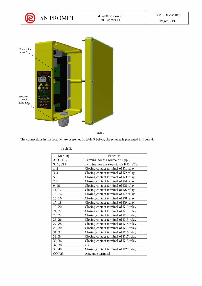
Figure 3
The connections in the receiver are presented in table 5 below; the scheme is presented in figure 4.
Table 5.
Marking Function
AC1, AC2 Terminal for the source of supply
ST1, ST2 Terminal for the stop circuit K21, K22
1, 2 Closing contact terminal of K1 relay
3, 4 Closing contact terminal of K2 relay
5, 6 Closing contact terminal of K3 relay
7, 8 Closing contact terminal of K4 relay
9, 10 Closing contact terminal of K5 relay
11, 12 Closing contact terminal of K6 relay
13, 14 Closing contact terminal of K7 relay
15, 16 Closing contact terminal of K8 relay
17, 18 Closing contact terminal of K9 relay
19, 20 Closing contact terminal of K10 relay
21, 22 Closing contact terminal of K11 relay
23, 24 Closing contact terminal of K12 relay
25, 26 Closing contact terminal of K13 relay
27, 28 Closing contact terminal of K14 relay
29, 30 Closing contact terminal of K15 relay
31, 32 Closing contact terminal of K16 relay
33, 34 Closing contact terminal of K17 relay
35, 36 Closing contact terminal of K18 relay
37, 38 n/a
39, 40 Closing contact terminal of K20 relay
CON23 Antennae terminal
Electronics
plate
Receiver
assembly
holes 4 pcs

SN PROMET
41-200 Sosnowiec
ul. Lipowa 11
IO-KR-01 (10.2017r)
Page: 10/13
Figure 4
Each relay is featured with a diode signalling its power-up and the D1 power supply presence and its proper D2
value.
There are two cut-outs in the RCR_01 receiver:
F1 - fast tubular fusible cut-out ∅5x20mm with rated voltage of 6.3A and rated current of 250VAC
F2 -fast tubular fusible cut-out ∅5x20mm with rated current of 500mA (for the 230V option) or 3.15A (for the
48V option) and rated voltage of 250VAC.
Cut-out scheme is presented on the figure below.
Figure 5
PO
WE
R
SU
PP
LY
UN
IT
SN PROMET
41-200 Sosnowiec
ul. Lipowa 11
IO-KR-01 (10.2017r)
Page: 11/13
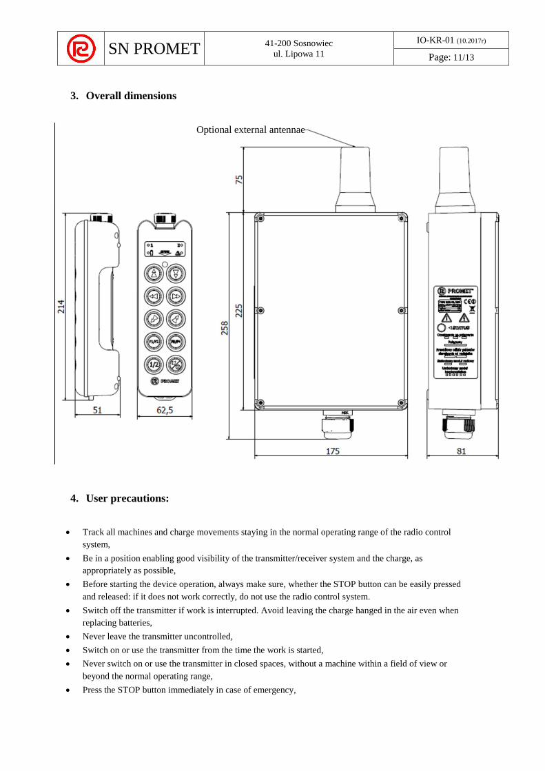
3. Overall dimensions
4. User precautions:
Track all machines and charge movements staying in the normal operating range of the radio control
system,
Be in a position enabling good visibility of the transmitter/receiver system and the charge, as
appropriately as possible,
Before starting the device operation, always make sure, whether the STOP button can be easily pressed
and released: if it does not work correctly, do not use the radio control system.
Switch off the transmitter if work is interrupted. Avoid leaving the charge hanged in the air even when
replacing batteries,
Never leave the transmitter uncontrolled,
Switch on or use the transmitter from the time the work is started,
Never switch on or use the transmitter in closed spaces, without a machine within a field of view or
beyond the normal operating range,
Press the STOP button immediately in case of emergency,
Optional external antennae

SN PROMET
41-200 Sosnowiec
ul. Lipowa 11
IO-KR-01 (10.2017r)
Page: 12/13
Pay attention to the entire working area. Press the STOP button immediately in case of emergency,
Do not allow the transmitter to get in contact with concrete, sand, lime grains, etc., as this may result
in damaging the device or its improper functioning,
In case of improper operation and/or damage and/or defective parts, stop the operation immediately
until the problem is solved,
From time to time, check the battery cover seal during replacement of the batteries; in case of any damage,
replace the seal,
During the battery replacement procedure, observe their polarity, screw the battery cover with bolts, and
press it in half-length so that it does not come off by final screwing home,
If the transmitter is not used for longer time, take out the batteries.
Used batteries or storage cells should not be thrown away with normal waste; they should be utilised
by throwing them into an appropriate container or taken to your collection point for hazardous
materials.
5. Fitter precautions:
The installation must be carried out by qualified personnel according to the installation standards,
Install the receiver vertically with the cable gland pointing downwards,
Install the receiver in the visible place, not exposed to atmospheric conditions
Install the receiver in 4 points using the holes on the housing corners under the cover,
You should not modify or interfere in radio control, the machine or its electrical panels,
Check whether the supply voltage is proper,
Do not bypass the safety circuits,
Observe the standards for lifting machines and/or for all machines,
Lay cables away from the radio module,
After installation and connecting the wiring system, check the operation of all circuits, in particular the
STOP circuit,
When installing the cover, check the seal with regard to damage, etc.,
6. Maintenance
Make sure that batteries have been taken out of the transmitter before performing any technical
maintenance activities
All activities related to the control and technical maintenance of the radio control system should be verified
and recorded by a person responsible for the machine technical maintenance
It is essential to carry out maintenance procedures according to these instructions in order to ensure safe
radio control system operation.
After each maintenance procedure, make sure whether all commands sent from the receiver start
appropriate operations.
6.1. Daily maintenance
Clean the transmitter of dust and other dirt not using high water pressure, water vapour, solvents, flammable
materials, corrosive agents
Store the transmitter in a dry and clean place
Check seals, rubber button casings with regard to wear-out signs, cracking as well as their elasticity and
flexibility.
SN PROMET
41-200 Sosnowiec
ul. Lipowa 11
IO-KR-01 (10.2017r)
Page: 13/13
Check whether the transmitter housing is not damaged, cracked or deformed
Check whether the descriptions are visible and replace them if necessary
Before starting work, check whether the STOP button works properly.
6.2. Periodic maintenance - every 3 months
Clean the receiver of dust and other dirt not using high water pressure, water vapour, solvents, flammable
materials, corrosive agents
Check whether the receiver housing is not damaged, cracked or deformed
Check whether the receiver wiring system is not damaged
6.3. Periodic maintenance - every 6 months
Check whether all receiver relay contacts function properly
Check whether commands sent to the receiver start desired operations and release them after the command is
no longer sent.
Additionally, each time when you open the receiver cover or transmitter battery chamber, check the sealing
condition.
In case of any defects in the set operation, contact the manufacturer and provide the following information:
Date of purchase
Supplier
Serial number (transmitter - you can find it under batteries, receiver - you can find it under the cover on the left,
next to the LED diode signalling the device operation status)
Correspondence address of the system operation place
Defect description
IV Appendices
1. Protection of the environment - utilisation of waste electronic equipment
The symbol of the crossed out bin means that, the equipment should be disposed of according to the Directive on
Waste Electric and Electronic Equipment of 11 September 2015.
The symbol meaning that the product should be collected and recycled, namely it should be utilised
separately from municipal waste and delivered to the appropriate local waste collecting point or handed over
to the Manufacturer or its service.
Proper disposal of the equipment can protect the natural environment and human health.
2. Scheme of assembly holes drilling