R THE FINEST RADIO CONTROL MODELS MR-03 … Setting Tie Rod Set (for MR-03) 840 SPARE PARTS <...
12
Before beginning assembly, please read these instructions thoroughly! MR03TG-T11 The MR-03 chassis features VCS (variable camber suspension) on the front unit that realizes camber change with suspension stroke. Also, the chassis can be set to either narrow or wide front tread by changing the tie rods and the upper and lower plates. With the four motor mount types and two front tread width settings, all body styles that are compatible with the MINI-Z Series MR-015 (MR-01), MR-02 and MA-010 (AWD) can be fitted to the one MR-03 main chassis. In addition, this Technical Guide has references to the 'Wiring Diagram', 'Circuit Breaker', and 'Converting to LL Wheelbase with LM Motor Mount'. Also, please use this as a reference for information on maintenance and tuning. ※ Tread indicates the width of the car (more accurately, tread is the distance between the middle of the tires on the right and left sides). MR-03 Features Thank you for purchasing the MINI-Z Racer MR-03. Please refer to this Technical Guide when changing the body, and to change the chassis type to suit your car body. 1 Type MM Type RM Type HM Type LM Motor Mount (Chassis Type) R THE FINEST RADIO CONTROL MODELS INSTRUCTION MANUAL MR-03 Technical Guide (Guide to Changing Body / Chassis Type) MINI-Z RACER ※ご使用前にこの説明書を良くお読みになり十分に理解してください。 MR-03シャシーはフロントユニットにVCS(バリアブルキャンバーサス)を搭載し、ストロークに応じたキャンバー変化を実現、また、アッパー&ロアプレートと タイロッドの交換により、同じシャシーでナローとワイドの2種類のフロントトレッドに変更を可能としました。これによりMR-03はひとつのメインシャシーに モーターマウント4種類、フロントトレッド幅2種類を組み合わせることが可能となり、今までのミニッツシリーズ<MR-015(MR-01)、MR-02、MA-010(AWD)>の すべてのボディを搭載することが可能です。 MR-03の特徴 / その他、「配線図」、「保護回路」、「LMモーターマウントを使用してのLLホイールベースコンバート方法」などについても記載しています。 メンテナンスやチューンナップの情報として参照してください。 ※トレッドとは車の幅を表します(厳密には左右のタイヤの中心を結ぶ長さ)。 ミニッツレーサーMR-03をお買い上げいただきましてまことにありがとうございます。 ボディを交換する際はこのテクニカルガイドを参照し、お手持ちのボディに適合するシャシータイプへ変更してください。 《MMタイプ》 《RMタイプ》 《HMタイプ》 《LMタイプ》 モーターマウント(シャシータイプ) 取扱説明書 MR-03 テクニカルガイド (ボディ/シャシータイプ変更ガイド) ミニッツレーサー
Transcript of R THE FINEST RADIO CONTROL MODELS MR-03 … Setting Tie Rod Set (for MR-03) 840 SPARE PARTS <...

Before beginning assembly, please read these instructions thoroughly!
MR03TG-T11
The MR-03 chassis features VCS (variable camber suspension) on the front unit that realizes camber change with suspension stroke. Also, the chassis can be set to eithernarrow or wide front tread by changing the tie rods and the upper and lower plates. With the four motor mount types and two front tread width settings, all body styles that are compatible with the MINI-Z Series MR-015 (MR-01), MR-02 and MA-010 (AWD) can be �tted to the one MR-03 main chassis.
In addition, this Technical Guide has references to the 'Wiring Diagram', 'Circuit Breaker', and 'Converting to LL Wheelbase with LM Motor Mount'. Also, please use this as a reference for information on maintenance and tuning.※ Tread indicates the width of the car (more accurately, tread is the distance between the middle of the tires on the right and left sides).
MR-03 Features
09.10
Thank you for purchasing the MINI-Z Racer MR-03. Please refer to this Technical Guide when changing the body, and to change the chassis type to suit your car body.
1
Type MM Type RM
Type HMType LM
Motor Mount (Chassis Type)
R
THE FINEST RADIO CONTROL MODELS
INSTRUCTION MANUALMR-03 Technical Guide (Guide to Changing Body / Chassis Type)MINI-Z RACER
A4(MR-03 Technical Guide)
※ご使用前にこの説明書を良くお読みになり十分に理解してください。
MR-03シャシーはフロントユニットにVCS(バリアブルキャンバーサス)を搭載し、ストロークに応じたキャンバー変化を実現、また、アッパー&ロアプレートとタイロッドの交換により、同じシャシーでナローとワイドの2種類のフロントトレッドに変更を可能としました。これによりMR-03はひとつのメインシャシーにモーターマウント4種類、フロントトレッド幅2種類を組み合わせることが可能となり、今までのミニッツシリーズ<MR-015(MR-01)、MR-02、MA-010(AWD)>のすべてのボディを搭載することが可能です。
MR-03の特徴 /
その他、「配線図」、「保護回路」、「LMモーターマウントを使用してのLLホイールベースコンバート方法」などについても記載しています。メンテナンスやチューンナップの情報として参照してください。※トレッドとは車の幅を表します(厳密には左右のタイヤの中心を結ぶ長さ)。
ミニッツレーサーMR-03をお買い上げいただきましてまことにありがとうございます。ボディを交換する際はこのテクニカルガイドを参照し、お手持ちのボディに適合するシャシータイプへ変更してください。
《MMタイプ》 《RMタイプ》
《HMタイプ》《LMタイプ》
モーターマウント(シャシータイプ)
取扱説明書
MR-03 テクニカルガイド (ボディ/シャシータイプ変更ガイド)
ミニッツレーサー

09.10
2
Wide Type Narrow Type
A4(MR-03 Technical Guide)
Firstly, make sure that the body style is compatible with the chassis type it is being �tted to.
How to Con�rm
Prepare according to either of the lists below.
Checking with the Optional Parts List data table
Con�rming with the model parts list
< >For MR-03 < >For MR-015/02
Parts List included with your model or Auto Scale Collection body set.
There are data tables for <MR-03N (Narrow)> and <MR-03W (Wide)>. Search the data table of your chassis to check the details shown.
Motor Mount Type
Front Tread Type
Narrow Type Wide Type : :N • MR-015 W • MR-02
Optional Parts List for the MR-03 (refer below for body styles for the MA-010 (AWD) → Please download from the 'MINI-Z Support Page' website below. (http://kyosho.com/mini-z-support/)
1
Check the 3 points below.
Front Tread
Motor Mount (Chassis Type)
Wheel Base
:
:
:
[N: Narrow Type], [W: Wide Type]
[MM], [LM], [RM], [HM]
For the RML, remove rear shock from the RM type.
[S], [M], [L], [LL], [3L], [4L]
2
Susp
ensi
on L
imite
rサスリミッター
Wh
ee
l Bas
eホ
イー
ルベ
ース
S : 8
6mm
M :
90m
mL
: 94m
mLL
: 98
mm
3L :
102m
m4L
: 10
6mm
Rear
Whe
el O
�set
(mm
)リヤホイールオフセット(mm)
Fron
t Whe
el O
�set
(mm
)フ
ロン
トホ
イー
ルオ
フセ
ット
(mm)
Fron
t Cha
ssis
Wid
th (m
m)
フロ
ント
シャ
シー
幅(m
m)
Rear
Cha
ssis
Wid
th (m
m)
リヤ
シャ
シー
幅(m
m)
Rece
iver
Ant
enna
D
Siz
e (m
m)
受信アンテナD寸
法(m
m)
Typ
e o
f C
has
sis
シャシータイプ
M 5 0 2 70 74 20MR-02(RM)
Wh
ee
l Bas
eホ
イー
ルベ
ース
S : 8
6mm
M :
90m
mL
: 94m
mLL
: 98
mm
3L :
102m
m4L
: 10
6mm
Rear
Whe
el O
�set
(mm
)リヤホイールオフセット(mm)
Fron
t Whe
el O
�set
(mm
)フ
ロン
トホ
イー
ルオ
フセ
ット
(mm)
Fron
t Cha
ssis
Wid
th (m
m)
フロ
ント
シャ
シー
幅(m
m)
Rear
Cha
ssis
Wid
th (m
m)
リヤ
シャ
シー
幅(m
m)
Rece
iver
Ant
enna
D
Siz
e (m
m)
受信アンテナD寸
法(m
m)
Typ
e o
f C
has
sis
シャシータイプ
M 0 0 65 65 (15)MR-03N / MR-015(HM)
Front Tread
Checking Body Compatibility
《ワイドタイプ》 《ナロータイプ》
まずは、お手持ちのボディに適合するシャシータイプを確認してください。
確認の方法
以下のいずれかのリストを用意してください。
「オプションパーツリストのデータ表」での確認の方法
「車種専用パーツリスト」での確認の方法
< >MR-03用 < >MR-015/02用
セットまたはオートスケールコレクションに付属する車種専用パーツリスト
データ表は<MR-03N(Narrow)>、<MR-03W(Wide)>があります。目的の車種を検索し、データ表の項目を確認してください。
モーターマウントの種類
フロントトレッドの種類
ナロータイプ ワイドタイプ: :N・MR-015 W・MR-02
以下の3点を確認してください。
フロントトレッド
モーターマウント(シャシータイプ)
ホイールベース
:
:
:
「N:ナロータイプ」、「W:ワイドタイプ」
「MM」、「LM」、「RM」、「HM」
※「RML」は「RM」からリヤダンパーを取外してください。
「S」、「M」、「L」、「LL」、「3L」、「4L」
MR-03用オプションパーツリスト【MA-010(AWD)用ボディはこちらにて確認】→ こちらはウェブサイト「ミニッツサポートページ」でダウンロードしてください。 (http://kyosho.com/mini-z-support/)
フロントトレッド
搭載ボディの確認

w
09.10
3
A4(MR-03 Technical Guide)
Diagram shows change from wide type to narrow type. However, reverse is the same.
Con�rm 'Front Tread', 'Motor Mount (chassis type)' and 'Wheelbase' at section on 'Checking Body Compatibility'.
Changing Front Tread
1 2x5mm
Front Spring
Lift and remove.
Pull outwards and remove.
2
3 42x6mm
2x6mm
2x6mm
2x6mm
1
1
2
2
1
3
< >Disassemble Front Suspension
Changing Chassis Type
イラストはワイドタイプからナロータイプへの変更ですが、逆の場合も同様です。
「搭載ボディの確認」で、「フロントトレッド」、「モーターマウント(シャシータイプ)」、「ホイールベース」を確認してください。
フロントトレッドの変更
フロントスプリング
ツメを外して取外す。
外側へ倒して取外す。
< >フロントサスペンションの分解
シャシータイプの変更

W
N
N
09.10
4
A4(MR-03 Technical Guide)
< >Assembling Front Suspension
4
2x6mm 2x6mm
2x5mm
3
Note the direction.
< >Completed
Front
1
2
2
Push ball until it clicks in. MZ406
MZ401
Use required lower arm type.
Wide Type Narrow Type
Use required Tie-Rod.
2 2x6mm
MZ403 or MZW402.
2x6mm
1
4
2 x 6mmTP Screw
4
2 x 6mmTP Screw
2
2 x 5mmTP Screw
Use required Upper Cover type.
Wide Type Narrow Type
1
1
2
3
No. Description
1050MZ401 Main Chassis Set (for MR-03)
630MZ403 Suspension Small Parts Set (for MR-03)
420MZ406 Front Suspension Arm Set (for MR-03)
840MZW402 Setting Tie Rod Set (for MR-03)
SPARE PARTS
< >フロントサスペンションの組立て
定価品番 パーツ名(税込)
メインシャシーセット(MR-03)
サスペンション小物セット(MR-03)
フロントサスペンションアームセット(MR-03)
セッティングタイロッドセット(MR-03)
向きに注意。
< >完成図
前
ボールをパチンとはめる。
MZ403又はMZW402
変更するLower Armを使用する。
ワイドタイプ ナロータイプ
変更するUpper Coverを使用する。
ワイドタイプ ナロータイプ
変更するTie-Rodを使用する。
TPビス
TPビス
TPビス
スペアパーツ
MR-03NVariable Tread System
MR-03WVariable Tread System
09.10
5
A4(MR-03 Technical Guide)
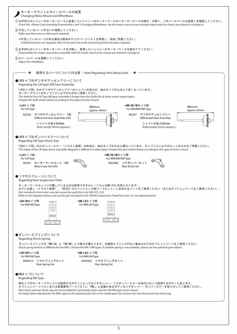
Regarding the LM type Di� Gear Assembly
Regarding LM Type Shock Stay
The shaft for the LM Type di� gear assembly is longer than the shafts for all other motor mount types. Prepare the shaft shown below according to the type of motor mount.
The shape of the LM Type shock stay (refer diagram) is di�erent to other types. Prepare the part shown below according to the type of motor mount.
Regarding RM Type
Rear shock and rear shock stay are not installed for some body styles used for the RM type motor mount.For body styles indicated for the RML type on the optional parts list or the model parts list, remove the rear shock and rear shock stay.
For LM Type
If additional parts are required, refer to the parts list at the end and purchase the parts required.
For MM/RM/HM Type
Check the <Motor Case Assembly/Disassembly> and <Changing Wheelbase> for the motor case on your existing chassis and the chassis you intend to change to. 1
Make sure there are no other parts required. 2
Disassemble the motor case and re-assemble with the motor case for the chassis you intend to change to. 3
Adjust the wheelbase. 4
Di�erential Gear Assembly (LM) Di�erential Gear Assembly
Shaft Length 69mm (approx.). Shaft Length 65mm (approx.).
Changing Motor Mount and Wheelbase
MZ302 MZ207
For LM Type For MM/RM/HM Type
Motor Case Set (LM) Rear Shock SetMZ301 MZ206B
Regarding Shock Spring
Shock spring tension is di�erent for the MM / LM and the RM / HM types. If suitable spring is not available, please use the optional parts below.
For RM/HM Type For MM/LM Type
Rear Spring Set Rear Spring SetMZW213 MZW202
Regarding Rear Suspension Plate
Part included in the motor case set cannot be used (this is for MR-015 / 02). Refer to the diagrams below and use the part included in the 'MZ403 Suspension Small Parts Set', (or use optional parts).
For RM/HM Type For MM/LM Type
approx. 69mm approx. 65mm
Note Regarding Parts Being Used
LMタイプのデフギヤアッセンブリーについて
「LMタイプ用」のみデフギヤアッセンブリーのシャフトの長さが、他のタイプのものより長くなっています。モーターマウントのタイプごとに以下のものをご用意ください。
LMタイプのダンパーステーについて
「LMタイプ用」のみダンパーステー(イラスト参照)の形状が、他のタイプのものと異なっています。タイプごとに以下のセットのものをご用意ください。
RMタイプについて
RMタイプのモーターマウントには使用するボディによってはリヤダンパー・リヤダンパーステーを取付けないで使用するボディもあります。オプションパーツリストまたは車種専用パーツリストに「RML」と記載があるボディはリヤダンパー・ダンパーステーを取り外してご使用ください。
お手持ちのシャシーのモーターケースと変更したいシャシーのモーターケースの<モーターケースの組立・分解>、<ホイールベースの変更>を確認してください。
不足しているパーツがないか確認してください。
お手持ちのシャシーのモーターケースを分解し、変更したいシャシーのモーターケースを組立ててください。
ホイールベースを調整してください。
LMタイプ用
不足しているパーツがある場合は巻末のスペアパーツリストを参照し、別途ご用意ください。
デフギヤアッセンブリー(LM) デフギヤアッセンブリー
シャフトの長さ約69mm シャフトの長さ約65mm
MM/RM/HMタイプ用
LMタイプ用
モーターケースセット(LM) リヤダンパーセット
MM/RM/HMタイプ用
ダンパースプリングについて
ダンパースプリングは「MM/LM」と「RM/HM」とで硬さが異なります。交換用スプリングがない場合は以下のオプションパーツをご使用ください。
RM/HMタイプ用
リヤスプリングセット リヤスプリングセット
MM/LMタイプ用
リヤサスプレートについて
モーターケースセットに付属しているものは使用できません(こちらはMR-015/02用となります)。以下に注意し(イラスト参照)、「MZ403 サスペンション小物パーツセット」に含まれるパーツをご使用ください(またはオプションパーツをご使用ください)。
RM/HMタイプ用 MM/LMタイプ用
モーターマウントとホイールベースの変更
約69mm 約65mm
使用するパーツについての注意 /

LL
3L
4L
MZ204MZ204
MZ153(MZ206B)
MZ207
MZ204
MZ203B
MZ204MZ403
2x5mm
2x6mm TPビス
MZ6BK
MZ6BK
MZ203B
MZ6BK
MZ6BK
MZ9PMZ204
2x8mm TPビスTP Screw
TPサラビスF/H TP Screw
2x5mm TPサラビスF/H TP Screw
TP Screw
2x6mm TPビスTP Screw
MZ153
MZW202
OP
OP
OP
OP
シャシーへTo Chassis
MM/LM
09.10
6
A4(MR-03 Technical Guide)
< >Motor Case Assembly / Disassembly
< >Changing Wheelbase
98mm 102mm 106mm
(4L)(3L)(LL)
Wheelbase (LL) Wheelbase (3L) Wheelbase (4L)
1
2 x 6mmTP Screw
1
2 x 5mmF/H TP Screw
2
2 x 8mmTP Screw
2x8mm(TP)2x6mm(TP)
2x5mm(F/H TP)
Power Unit
Power Unit
Shock Stay (For MM/RM/HM Type)
Shock Spring (For MM/LM Type)
MMtype
2 x 6mmTP Screw
2 x 5mmF/H TP Screw
2 x 8mmTP Screw
If changing the pinion gear, refer to the section "Replacing Pinion Gear".
When installing on chassis refer to section "Changing Wheelbase".
Use the motor, tires, gears and shaft shown in faded outline on the diagram above from your existing chassis.
Optional parts should be used for the parts marked with . OP
< >モーターケースの組立・分解
< >ホイールベースの変更
ホイールベース(LL) ホイールベース(3L) ホイールベース(4L)
TPビス
TPサラビス
TPビス
TPビス
TPサラビス
TPビス
の印が付いたパーツはオプションパーツをご利用ください。OP
パワーユニット
パワーユニット
ダンパーステー「MM/RM/HMタイプ用」
ダンパースプリング「MM/LMタイプ用」
ピニオンギヤを交換する場合は、取扱説明書の『ピニオンギヤの交換』を参照してください。
シャシーへの取付けは、『ホイールベースの変更』を参照してください。
上図のモーター・タイヤ・ギヤ・シャフトなど薄く表示されている部品は、お手持ちのシャシーよりご使用ください。
S
M
L
2x5mm
2x6mm TPビス
2x8mm TPビスTP Screw
TPサラビスF/H TP Screw
2x6mm TPビスTP Screw
2x6mm TPビスTP Screw
TP Screw
シャシーへTo Chassis
MZ207
MZ203B
MZ403
MZ210
MZ6BK
MZ203B
MZ6BK
MZ6BK
MZ210
MZ6BK
MZ6BK
MZ9P
OP
OP
MZ210
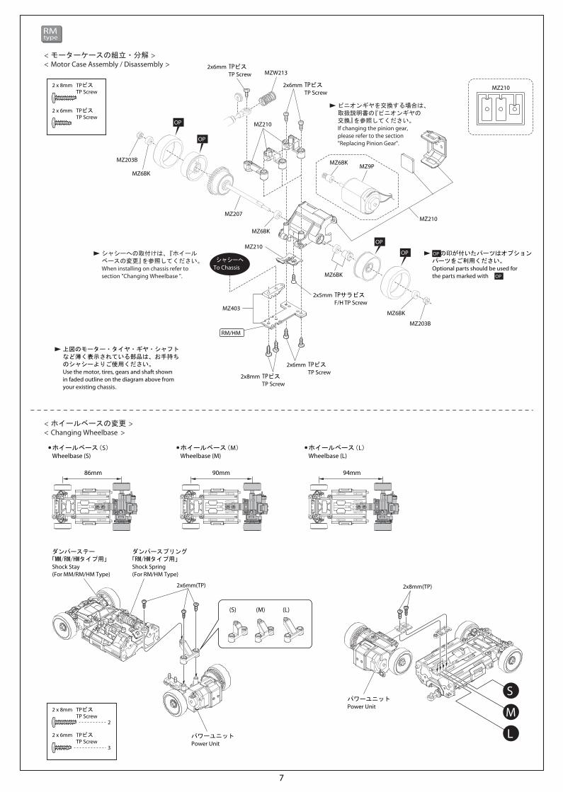
RM/HM
MZ210
MZW213
OP
OP
09.10
7
A4(MR-03 Technical Guide)
< >Motor Case Assembly / Disassembly
< >Changing Wheelbase
(L)(M)(S)
Wheelbase (S) Wheelbase (M) Wheelbase (L)
3
2 x 6mmTP Screw
2
2 x 8mmTP Screw
2 x 6mmTP Screw
2 x 8mmTP Screw
2x8mm(TP)2x6mm(TP)
Power Unit
Power Unit
RMtype
If changing the pinion gear, please refer to the section"Replacing Pinion Gear".
When installing on chassis refer to section "Changing Wheelbase ".
Use the motor, tires, gears and shaft shown in faded outline on the diagram above from your existing chassis.
Optional parts should be used for the parts marked with . OP
94mm90mm86mm
Shock Stay (For MM/RM/HM Type)
Shock Spring (For RM/HM Type)
< >モーターケースの組立・分解
< >ホイールベースの変更
ホイールベース(S) ホイールベース(M) ホイールベース(L)
TPビス
TPビス
TPビス
TPビス
の印が付いたパーツはオプションパーツをご利用ください。OP
パワーユニット
パワーユニット
ピニオンギヤを交換する場合は、取扱説明書の『ピニオンギヤの交換』を参照してください。
シャシーへの取付けは、『ホイールベースの変更』を参照してください。
上図のモーター・タイヤ・ギヤ・シャフトなど薄く表示されている部品は、お手持ちのシャシーよりご使用ください。
ダンパーステー「MM/RM/HMタイプ用」
ダンパースプリング「RM/HMタイプ用」

3L
9T
9T7T
7T
2x6mm TPビスTP Screw
2x6mm TPビスTP Screw
MZW202
2x6mm TPビス
2x8mm TPビスTP Screw
TP Screw
シャシーへTo Chassis
OP
OP
OP
OP
MZ403
MZ301MZ301
MZ301
MZ302
MZ301
MZ203B
MZ301
MZ301
MZ6BK
MZ6BK
MZ203B
MZ6BK
MZ6BK
MZ9P
MZ301
2x5mm TPサラビスF/H TP Screw
2x5mm TPサラビスF/H TP Screw
MM/LM
09.10
8
A4(MR-03 Technical Guide)
< >Motor Case Assembly / Disassembly
< >Changing Wheelbase
Wheelbase (3L)
5
2 x 6mmTP Screw
2
2 x 8mmTP Screw
2x8mm(TP)2x6mm(TP)
Power Unit
2x6mm(TP)
2x6mm(TP)
LMtype
If changing the pinion gear, refer to the section "Replacing Pinion Gear".
When installing on chassis refer to section "Changing Wheelbase".
Use the motor, tires, gears and shaft shown in faded outline on the diagram above from your existing chassis.
Optional parts should be used for the parts marked with .
Wheelbase for the LM Type is 3L only.
OP
102mm
2 x 6mmTP Screw
2 x 5mmF/H TP Screw
2 x 8mmTP Screw
Shock Stay (For LM Type)
Shock Spring (For MM/LM Type)
< >モーターケースの組立・分解
< >ホイールベースの変更
ホイールベース(3L)
TPビス
TPビス
の印が付いたパーツはオプションパーツをご利用ください。OP
パワーユニット
ピニオンギヤを交換する場合は、取扱説明書の『ピニオンギヤの交換』を参照してください。
シャシーへの取付けは、『ホイールベースの変更』を参照してください。
LMタイプのホイールベースは3Lのみです。
上図のモーター・タイヤ・ギヤ・シャフトなど薄く表示されている部品は、お手持ちのシャシーよりご使用ください。
TPビス
TPサラビス
TPビス
ダンパーステー「LMタイプ用」
ダンパースプリング「MM/LMタイプ用」

S
M
L
2x5mm TPサラビスF/H TP Screw
2x6mm TPビスTP Screw
2x6mm TPビスTP Screw
MZW213
MZ154
MZ154
MZ154
2x6mm TPビス
2x8mm TPビスTP Screw
TP Screw
シャシーへTo Chassis
MZ154
OP
OP
OP
OP
MZ207
MZ203B
MZ6BK
MZ203B
MZ6BK
MZ6BK
MZ6BK
MZ6BK
MZ9P
MZ154
MZ154
MZ403
MZ154
RM/HM
09.10
9
A4(MR-03 Technical Guide)
< >Motor Case Assembly / Disassembly
< >Changing Wheelbase
(L)(M)(S)
Wheelbase (S) Wheelbase (M) Wheelbase (L)
3
2 x 6mmTP Screw
2
2 x 8mmTP Screw
2x8mm(TP)2x6mm(TP)
2x6mm(TP)
Power Unit
Power Unit
HMtype
If changing the pinion gear, refer to the section "Replacing Pinion Gear".
When installing on chassis refer to section "Changing Wheelbase".
Use the motor, tires, gears and shaft shown in faded outline on the diagram above from your existing chassis.
Optional parts should be used for the parts marked with . OP
94mm90mm86mm
2 x 6mmTP Screw
2 x 5mmF/H TP Screw
2 x 8mmTP Screw
Shock Stay (For MM/RM/HM Type)
Shock Spring (For RM/HM Type)
< >モーターケースの組立・分解
< >ホイールベースの変更
ホイールベース(S) ホイールベース(M) ホイールベース(L)
TPビス
TPビス
の印が付いたパーツはオプションパーツをご利用ください。OP
パワーユニット
パワーユニット
ピニオンギヤを交換する場合は、取扱説明書の『ピニオンギヤの交換』を参照してください。
シャシーへの取付けは、『ホイールベースの変更』を参照してください。
上図のモーター・タイヤ・ギヤ・シャフトなど薄く表示されている部品は、お手持ちのシャシーよりご使用ください。
TPビス
TPサラビス
TPビス
ダンパーステー「MM/RM/HMタイプ用」
ダンパースプリング「RM/HMタイプ用」
09.10
10
A4(MR-03 Technical Guide)
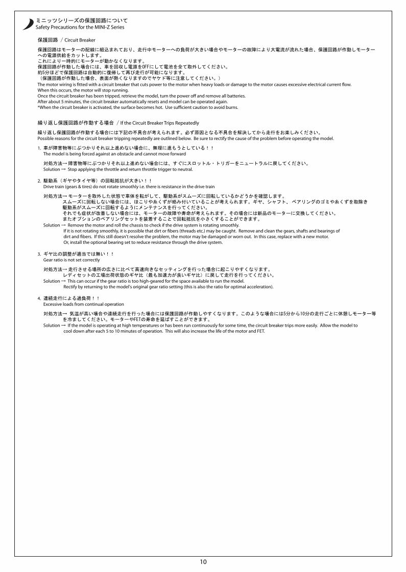
Safety Precautions for the MINI-Z Series
Circuit Breaker
1.
The motor wiring is �tted with a circuit breaker that cuts power to the motor when heavy loads or damage to the motor causes excessive electrical current �ow. When this occurs, the motor will stop running. Once the circuit breaker has been tripped, retrieve the model, turn the power o� and remove all batteries. After about 5 minutes, the circuit breaker automatically resets and model can be operated again. *When the circuit breaker is activated, the surface becomes hot. Use su�cient caution to avoid burns.
If the Circuit Breaker Trips Repeatedly
Possible reasons for the circuit breaker tripping repeatedly are outlined below. Be sure to rectify the cause of the problem before operating the model.
Solution → Stop applying the throttle and return throttle trigger to neutral.
The model is being forced against an obstacle and cannot move forward
2.
Solution → Remove the motor and roll the chassis to check if the drive system is rotating smoothly. If it is not rotating smoothly, it is possible that dirt or �bers (threads etc.) may be caught. Remove and clean the gears, shafts and bearings of dirt and �bers. If this still doesn't resolve the problem, the motor may be damaged or worn out. In this case, replace with a new motor. Or, install the optional bearing set to reduce resistance through the drive system.
Drive train (gears & tires) do not rotate smoothly i.e. there is resistance in the drive train
3.
Solution → This can occur if the gear ratio is too high-geared for the space available to run the model. Rectify by returning to the model's original gear ratio setting (this is also the ratio for optimal acceleration).
Gear ratio is not set correctly
4.
Solution → If the model is operating at high temperatures or has been run continuously for some time, the circuit breaker trips more easily. Allow the model to cool down after each 5 to 10 minutes of operation. This will also increase the life of the motor and FET.
Excessive loads from continual operation
ミニッツシリーズの保護回路について
保護回路はモーターの配線に組込まれており、走行中モーターへの負荷が大きい場合やモーターの故障により大電流が流れた場合、保護回路が作動しモーターへの電源供給をカットします。これにより一時的にモーターが動かなくなります。保護回路が作動した場合には、車を回収し電源をOFFにして電池を全て取外してください。約5分ほどで保護回路は自動的に復帰して再び走行が可能になります。(保護回路が作動した場合、表面が熱くなりますのでヤケド等に注意してください。)
保護回路 /
車が障害物等にぶつかりそれ以上進めない場合に、無理に進もうとしている!!
繰り返し保護回路が作動する場合には下記の不具合が考えられます。必ず原因となる不具合を解決してから走行をお楽しみください。
繰り返し保護回路が作動する場合 /
対処方法→ 障害物等にぶつかりそれ以上進めない場合には、すぐにスロットル・トリガーをニュートラルに戻してください。
駆動系(ギヤやタイヤ等)の回転抵抗が大きい!!
対処方法→ モーターを取外した状態で車体を転がして、駆動系がスムーズに回転しているかどうかを確認します。 スムーズに回転しない場合には、ほこりや糸くずが絡み付いていることが考えられます。ギヤ、シャフト、 ベアリングのゴミや糸くずを取除き 駆動系がスムーズに回転するようにメンテナンスを行ってください。 それでも症状が改善しない場合には、モーターの故障や寿命が考えられます。その場合には新品のモーターに交換してください。 またオプションのベアリングセットを装着することで回転抵抗を小さくすることができます。
ギヤ比の調整が適当では無い!!
対処方法→ 走行させる場所の広さに比べて高速向きなセッティングを行った場合に起こりやすくなります。 レディセットの工場出荷状態のギヤ比(最も加速力が良いギヤ比)に戻して走行を行ってください。
連続走行による過負荷!!
対処方法→ 気温が高い場合や連続走行を行った場合には保護回路が作動しやすくなります。このような場合には5分から10分の走行ごとに休憩しモーター等 を冷ましてください。モーターやFETの寿命を延ばすことができます。
09.10
11
A4(MR-03 Technical Guide)
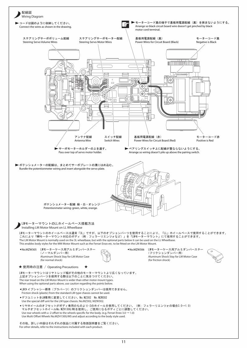
The LM Motor Mount is normally used on the 3L wheelbase, but with the optional parts below it can be used on the LL Wheelbase.This enables body styles for the MM Motor Mount such as the Ferrari Enzo etc. to be �tted on the LM Motor Mount.
The rear tread on the LM Motor Mount is wider than other motor mount types.When using the optional parts above, use caution regarding the points below.
For other details, refer to the instructions included with each product.
Installing LM Motor Mount on LL Wheelbase
Friction shock (plastic) from the standard LM type chassis cannot be used.
Use the special di� unit for the LM type chassis. No.MZ302, MZW302.
Use rear wheels with a -2 o�set to the wheels speci�c for the body. (e.g. Ferrari Enzo 3.0 → 1.0)Use Multi O�set Wheels No.MZH130G/MS and adjust according to the body style used.
Aluminum Shock Stay for LM Motor Case (for friction shock)
No.MZW306
Aluminum Shock Stay for LM Motor Case (for normal shock)
No.MZW305
Arrange so black circuit board wire doesn't get pinched by black motor cord terminal.
Steering Servo Volume Wires
Antenna Wire
Power Wires for Circuit Board (Black)Steering Servo Motor Wires Negative is Black
Positive is RedSwitch Wires Power Wires for Circuit Board (Red)
Potentionmeter wiring: green, white, orange.
Wiring Diagram
Connect the wires as shown in the drawing.
Bundle the potentionmeter wiring and insert alongside the servo plate.
Pass over top of servo motor holder. Arrange so wiring doesn't pile up above the pairing switch.
Operating Precautions
LMタイプシャシー標準(プラパーツ)のフリクションダンパーは使用できません。
デフユニットをLM専用に変更してください。No.MZ302 No.MZW302
リヤホイールのオフセットがボディ専用のものより-2のホイールを使用してください。(例:フェラーリエンツォの場合3.0→1.0)マルチオフセットホイールNo.MZH130G/MSを使用し、ご使用になるボディごとに調整してください。
LMモーターケース用アルミダンパーステー(フリクションダンパー用)
LMモーターケース用アルミダンパーステー(ノーマルダンパー用)
LMモーターマウントのホイールベースは通常「3L」ですが、以下のオプションパーツを使用することにより、「LL」ホイールベースで使用することができます。これにより「MMモーターマウント対応のボディ(例:フェラーリエンツォなど)」を「LMモーターマウント」にて使用することができます。
LMモーターマウントはリヤトレッド幅がその他のモーターマウントより広くなっています。上記オプションパーツを使用する際は以下のことに気をつけてください。
その他、詳しい内容はそれぞれの製品に付属する取扱説明書をご覧ください。
LMモーターマウントのLLホイールベース搭載方法
モーターコード黒の端子で基板用電源配線(黒)を挟まないようにする。
ステアリングサーボモーター配線
モーターコード赤
ステアリングサーボボリューム配線
アンテナ配線
基板用電源配線(黒)
基板用電源配線(赤)
ポテンショメーター配線 緑・白・オレンジ
モーターコード黒
スイッチ配線
配線図
コードは図のように収納してください。
ポテンショメーターの配線は、まとめてサーボプレートの溝にはめ込む。
サーボモーターホルダーの上を通す。 ペアリングスイッチ上に配線が重ならないようにする。
使用時の注意 /
9T
9T7T
7T
09.10
12
A4(MR-03 Technical Guide)
© Copyright 2009 KYOSHO CORPORATION / 禁無断転載複製
メーカー指定の純正部品を使用して
安全にR/Cを楽しみましょう。
※製品改良のため、予告なく仕様を変更する場合があります。*SPECIFICATIONS ARE SUBJECT TO CHANGE WITHOUT NOTICE.
0910-1WEB PRINTED IN JAPAN
京商株式会社〒243-0034 神奈川県厚木市船子153
●ユ-ザ-相談室直通電話 046-229-4115お問い合せは:月曜~金曜(祝祭日を除く)10:00~18:00
京商ホームページwww.kyosho.com
ミニッツ専用ホームページwww.mini-z.jp/
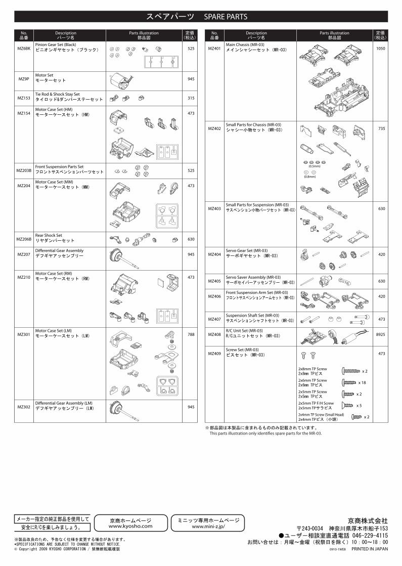
No. Description Parts illustration No. Description Parts illustration
This parts illustration only identi�es spare parts for the MR-03.
SPARE PARTS
525
945
MZ6BK
MZ9P
Pinion Gear Set (Black)
Motor Set
ピニオンギヤセット(ブラック)
モーターセット
315MZ153Tie Rod & Shock Stay Setタイロッド&ダンパーステーセット
473MZ154Motor Case Set (HM)モーターケースセット(HM)
630
473
MZ206B
MZ204
Rear Shock Setリヤダンパーセット
Motor Case Set (MM)モーターケースセット(MM)
525MZ203BFront Suspension Parts Setフロントサスペンションパーツセット
945MZ207Di�erential Gear Assemblyデフギヤアッセンブリー
473MZ210Motor Case Set (RM)モーターケースセット(RM)
788MZ301Motor Case Set (LM)モーターケースセット(LM)
945MZ302Di�erential Gear Assembly (LM)デフギヤアッセンブリー(LM)
1050MZ401Main Chassis (MR-03)メインシャシーセット(MR-03)
735MZ402Small Parts for Chassis (MR-03)シャシー小物セット(MR-03)
630MZ403Small Parts for Suspension (MR-03)サスペンション小物パーツセット(MR-03)
420MZ404Servo Gear Set (MR-03)サーボギヤセット(MR-03)
630MZ405Servo Saver Assembly (MR-03)サーボセイバーアッセンブリー(MR-03)
420MZ406Front Suspension Arm Set (MR-03)フロントサスペンションアームセット(MR-03)
473MZ407Suspension Shaft Set (MR-03)サスペンションシャフトセット(MR-03)
8925MZ408
MZ409
R/C Unit Set (MR-03)R/Cユニットセット(MR-03)
473Screw Set (MR-03)ビスセット(MR-03)
2x8mm TPビス2x8mm TP Screw
2x6mm TPビス2x6mm TP Screw
2x5mm TPビス2x5mm TP Screw
2x5mm TPサラビス2x5mm TP F/H Screw
2x4mm TPビス(小頭)2x4mm TP Screw (Small Head)
x 2
x 18
x 2
x 5
x 2
(0.5mm)
(0.8mm)
スペアパーツ
定価品番 パーツ名 部品図 (税込)
定価品番 パーツ名 部品図 (税込)
部品図は本製品に含まれるもののみ記載されています。


![[KATO] Assyパーツ情報](https://static.fdocument.pub/doc/165x107/61965650d1f43c73b20ac8e8/kato-assy.jpg)