
Quest Technologiesmultimedia.3m.com/mws/media/760843O/aq5000-5001... · Quest Warranty Policy Quest...
28
Quest Technologies aq Series Indoor Air Quality Monitors Manual 2145-003 Rev. A 6/00 Table Of Contents Chapter 1: Introduction…………………………………………….……………… 1 Chapter 2: Getting Started………………………………………..……………….. 3 Before You Begin …………………………………………………………………… 3 Check to Make Sure You have the Right Hardware………………………. 3 Using AC Power and the Internal Battery…………………………………... 3 Setting the Real Time Clock…………………………………………………. 7 Selecting Channels…………………………………………………………… 7 Default Recorder Setup……………………………………………………… 8 Chapter 3: Quick Tutorial………………………………………………………… 9 o and Off …………………………………………. 9 Turning the lAQ M nitor On Calibrating the CO Sensor ……………………………………………………... 9 2 Viewing Information with the IAQ Monitor……………………………………. 11 Recording ……………………………………………………….. 11 Start and Stop Output Reports …………………………………………………….……………… 12 Clearing Data from the IAQ Monitor …………………………………………… 13 Chapter 4: Detailed Instructions………………………………………………. 15 Turning the IAQ Monitor On and Off ………………………………………….. 19 Connecting and Calibrating Sensors …………………………………………. 21 CO , Temperature and Humidity Sensors………………………………. 21 2 Toxic Gas Sensors…………………………………………………………. 25 Linear Input Sensor………………………………………………………… 38 ………………………………….. 38 Helpful Hints for Calibrating Sensors… Viewing Information with the IAQ Monitor……………………………………. 39 Start and Stop Recording …………………………………………….………… 42 …………………………..………... 43 Out putting Reports Directly to a Printer Clearing Data from the IAQ Monitor ………………………………………….. 45 Secure Mode ……………………………………………………….. ……………. 47 Chapter 5: Specifications & Accessories…………………………………….. 49 Specifications …………………………………………………………………….. 49 sories………………………………………………………………………… 51 Acces Index………………………………………………………………………………… 53
Transcript of Quest Technologiesmultimedia.3m.com/mws/media/760843O/aq5000-5001... · Quest Warranty Policy Quest...

Quest Technologies aq Series
Indoor Air Quality Monitors Manual
2145-003
Rev. A 6/00
Table Of Contents Chapter 1: Introduction…………………………………………….……………… 1 Chapter 2: Getting Started………………………………………..……………….. 3 Before You Begin …………………………………………………………………… 3
Check to Make Sure You have the Right Hardware………………………. 3 Using AC Power and the Internal Battery…………………………………... 3 Setting the Real Time Clock…………………………………………………. 7 Selecting Channels…………………………………………………………… 7 Default Recorder Setup……………………………………………………… 8
Chapter 3: Quick Tutorial………………………………………………………… 9
o and Off …………………………………………. 9 Turning the lAQ M nitor OnCalibrating the CO Sensor ……………………………………………………... 9 2
Viewing Information with the IAQ Monitor……………………………………. 11 Recording ……………………………………………………….. 11 Start and Stop
Output Reports …………………………………………………….……………… 12 Clearing Data from the IAQ Monitor …………………………………………… 13 Chapter 4: Detailed Instructions………………………………………………. 15 Turning the IAQ Monitor On and Off ………………………………………….. 19 Connecting and Calibrating Sensors …………………………………………. 21
CO , Temperature and Humidity Sensors………………………………. 21 2
Toxic Gas Sensors…………………………………………………………. 25 Linear Input Sensor………………………………………………………… 38
………………………………….. 38 Helpful Hints for Calibrating Sensors…Viewing Information with the IAQ Monitor……………………………………. 39 Start and Stop Recording …………………………………………….………… 42
…………………………..………... 43 Out putting Reports Directly to a PrinterClearing Data from the IAQ Monitor ………………………………………….. 45 Secure Mode ……………………………………………………….. ……………. 47 Chapter 5: Specifications & Accessories…………………………………….. 49 Specifications …………………………………………………………………….. 49
sories………………………………………………………………………… 51 AccesIndex………………………………………………………………………………… 53
Quest Warranty Policy Quest Technologies warrants our instruments to be free from defects in materials and workman-ship for one year under normal conditions of use and service. For U.S.A. customers we will replace or repair (our option) defective instruments at no charge, excluding batteries, abuse, misuse, alterations, physical damage, or instruments previously repaired by other than Quest Technologies. Microphones. sensors, and printers may have shorter warranty periods. This warranty states our total obligation in place of any other warranties expressed or implied. Our warranty does not include any liability or obligation directly resulting from any defective instrument or product or any associated damages, injuries, or property loss, including loss of use or measurement data. For warranty outside the U.S.A., a minimum one-year warranty applies to the same limitation of exceptions as above with service provided or arranged through the authorized Quest distributor or our Quest European Service Laboratory. Foreign purchasers should contact the local Quest distributor for details.
Quest Service Policy The Quest product you have purchased is one of the finest IAQ instruments available. It is backed by our full one-year warranty. which seeks complete customer satisfaction. This is your assurance that you can expect prompt courteous service for your equipment from the entire Quest service organization. Should your Quest equipment need to be returned for repair or re-calibration, please contact the Service Department at (800) 245-0779 (USA) or Fax (414) 567-4047 for a Return Authorization Number. The RA number is valid for 30 days, and must be shown on the shipping label and purchase order/cover letter. If you are unable to return instruments in that time call for a new RA number. Send it prepaid and properly packed in the original shipping carton directly to Quest Technologies, 1060 Corporate Center Drive, Oconomowoc, WI 53066 U.S.A. Repair or replacement work done under warranty will be performed free of charge, and the instrument will be returned to you prepaid. Your copy or a photocopy of the Quest registration Card will serve as proof of warranty should the factory require this information. If for any reason you should find it necessary to contact the factory regarding service or shipping damage, please direct your calls or letters to the attention of the Service Manager, Quest Technologies, (262) 567-9157 or (800) 245-0779. Office hours are from 7 AM to 6 PM (Central Standard Time) Monday through Friday. For service or re-calibration outside the U.S. A., please contact your local Quest Dealer or fax Quest U.S.A. at 1-262-567-4047.
Chapter 1: Introduction Congratulations on purchasing Quest Technologies aq Series Indoor Air Quality Monitor. The aq Series consists of the IAQ Monitor Hand-Held Indoor Air Quality Monitor and the aq-5001 Portable Indoor Air Quality Monitor. As you will see in this instruction manual, you can easily convert the aq-5001 into the IAQ Monitor Hand-Held version as the need arises. Quest Technologies aq Series IAQ Monitors, measure, display and record data on up to five channels. Each channel permits monitoring one of the following: carbon dioxide, temperature, relative humidity, toxic gas, and a linear input. The carbon dioxide, temperature and relative humidity inputs are built into the monitoring unit. The toxic gas input allows you to use Quest Technologies optional toxic gas sensors to measure any of the following gases: carbon monoxide, hydrogen sulphide, sulfur dioxide, chlorine, nitrogen dioxide, nitric oxide, oxygen, hydrogen cyanide and ammonia. The linear input provides the flexibility to attach your own input source and monitor additional pollutants. All chosen channels are measured simultaneously, allowing information to be correlated and compared. QuestSuite™ is available for use with the aq Series Monitors. This software is totally menu driven and easy to use. It allows programming your air quality monitor within seconds, creating graphs and reports, performing database searches and more!
IMPORTANT! Register your IAQ Monitor/aq-5001 Indoor Air Quality Monitor NOW. Simply fill out and mail the enclosed warranty card.
www.quest-technologies.com

Chapter 2: Getting Started Before You Begin Check to Make Sure You have the Right Hardware The following is a list of requirements for any computer or printer to work with your IAQ Monitor:
• Serial RS-232 communications using at least the transmit (TX pin
2), receive (RX pin 3) and common ground (GND pin 7) lines • Accept XON/XOFF software handshaking, also known as DC1/
DC3 or CtrlS/CtrlQ • Accept a baud rate of 1200, 2400, 4800, 9600, 19200 or 38400
baud • Data format of 1 start bit, 8 data bits, 1 stop bit and no parity • Accept the standard ASCII character set • Support 80 column printouts
Using AC Power and the Internal Battery The aq Series Monitors come with an AC power adapter and a set of four AA alkaline batteries. An optional sealed rechargeable battery pack is also available. Call Quest Technologies Sales Department at 800-245-0779 for more information on this option. Either AC power or internal batteries can be used to supply power to the IAQ Monitor during tests; whichever best suits your needs. The batteries are convenient for walkthrough surveys, while AC power offers longer monitoring sessions. In addition to powering the IAQ Monitor, the internal batteries also provide a back up power source for programming and data retention. The batteries MUST have a voltage of greater than 4.1 volts to properly operate the IAQ Monitor. If the battery drops below 4.1 volts while the IAQ Monitor is operating, the IAQ Monitor will automatically shut down and save the data already in memory and the programming information for 30 days. This allows plenty of time for you to change or recharge the batteries.
Chapter 2 Getting Started You can check the current battery voltage by turning on the IAQ Monitor and pressing the arrow key (see "Reviewing the IAQ Monitor's Status" in Chapter 4). NOTE: The IAQ Monitor draws power from the internal batteries in order to maintain the clock and store programming information in memory. If the IAQ Monitor will not be used for an extended period of time, the batteries should be removed. New batteries should be installed when the IAQ Monitor is used again. Replacing the Internal AA Batteries The procedure for replacing the AA batteries is very simple and can easily be performed within seconds. The IAQ Monitor will maintain its programming information and logged data during battery replacement, provided that the replacement procedure DOES NOT take more than 2 minutes. The IAQ Monitor MUST be turned off before removing the bottom end-cap. If the IAQ Monitor is turned on when the battery is removed, all programming and logged data will be lost. Follow these instructions to replace the AA batteries in the IAQ Monitor (be sure you have fresh batteries ready before beginning this procedure):
1. Turn the IAQ Monitor off by pressing the ON/OFF button.
2. Use a phillips-head screwdriver to loosen the screw on the battery door, located on the bottom end-cap of the IAQ Monitor, and then remove the battery door.
3. Tilt the IAQ Monitor towards you and tap it on your hand so the old
batteries slide out.
4. Slide the fresh batteries into the battery compartment with the + and - terminals matching the diagram on the back label of the unit. The batteries must be installed in less than 2 minutes to prevent possible data loss.
5. Replace the battery door and tighten the screw so that it fits
securely and the opening is sealed.
Chapter 2 Getting Started Optional Battery Pack These instructions are only applicable if you have purchased the optional NIMH Battery Pack (part #2070-7050). Installing the Battery Pack Follow these instructions to install the optional battery pack in the IAQ Monitor (be sure you have the battery pack handy before beginning this procedure):
1. Turn the IAQ Monitor off by pressing the ON/OFF button.
2. Use a phillips-head screwdriver to loosen the screw on the battery door, located on the bottom end-cap of the IAQ Monitor, and then remove the battery door.
3. Tilt the IAQ Monitor towards you and tap it on your hand so the old
batteries/battery pack slide out.
4. Slide the battery pack into the battery compartment. With the front panel on the IAQ Monitor facing the ceiling, insert the battery pack so that the contacts face down. The label on the battery pack has an arrow that indicates which end goes in first. The battery pack must be installed in less than 2 minutes to prevent possible data loss.
5. Replace the battery door and tighten the screw so that it fits
securely and the opening is sealed. Charging the Battery Pack If you will be using the battery pack as your power source, we recommend fully charging it before you begin recording data. Charging the battery pack requires a Charger/Manager (part # 2070-8055) and an AC Charger (part #2070-8050-01 or 2070-8050-02). To recharge the battery pack:
1. Turn the IAQ Monitor off by pressing the ON/OFF button.
Chapter 2 Getting Started
2. Quest Technologies offers two different AC chargers for the battery pack. Follow the instructions for the AC charger that you have: 2070-8050-01: Plug the 2070-8050-01 AC charger into a 120 VAC, 50 or 60 hz, power source. Next, plug the AC charger into the dc input connector of the Charger/Manager.
2070-8050-02: Plug the power cord into a power source with the voltage between 100 and 240 VAC, 50 or 60 hz, and then plug the other end of the power cord into the 2070-8050-02 AC charger. Next, plug the AC charger into the dc input connector of the Charger/Manager.
3. Plug the 5-pin connector of the Charger/Manager into the battery
charger input on the top end-cap of the IAQ Monitor (see the IAQ Monitor instrument diagram at the beginning of Chapter 4 to locate the 5-pin connector). A few seconds later, the LED on the Charger/ Manager will turn red, indicating a high rate charging condition.
4. A fully discharged battery pack will take at least 3 hours to
completely recharge. Less discharged packs will recharge sooner. Upon completion of the high rate charge, the Charger/Manager's LED will turn green. Leave the Charger/Manager connected for 30 minutes after the LED turns green and the battery pack will be completely recharged.
5. You can now disconnect the AC charger from the IAQ Monitor.
NOTE: While recharging the battery pack, the LED on the C Charger/Manager will indicate problems as follows:
1. A flashing red LED on the Charger/Manager indicates: a. A low voltage from the AC charger. This can be caused by either a power source problem or a bad AC charger. b. The battery pack has shorted batteries.
2. A yellow LED on the Charger/Manager indicates the battery pack is
outside of its temperature range of -10 to +35°C (+14 to +95°F). Charging will not continue until the ambient temperature is within this range.
NOTE: The battery pack is not damaged by leaving the Charger/Manager connected after the LED turns green.

Chapter 2 Getting Started NOTE: The battery pack should not be allowed to become fully discharged or left in a "low charge" state for an extended period of time. If left unused, the battery should be recharged every three months and before using the IAQ Monitor. Setting The Real Time Clock If you want the IAQ Monitor to record in real time, you must use QuestSuite™ to set the real time clock before you begin recording. QuestSuite™ automatically sets the real time clock of the IAQ Monitor to the current time at your computer when you program the IAQ Monitor for a test (see the on-line help in QuestSuite™ for more information). Selecting Channels The IAQ Monitor comes with the following 5 channels:
1. Carbon Dioxide (CO2) 2. Temperature 3. Relative Humidity 4. Toxic Gas 5. Linear Input
You can record data on any or all of these channels. The IAQ Monitor comes factory programmed with the CO2, temperature and humidity channels turned on (they will be recorded), and the toxic gas and linear channels turned off (they will not be recorded). The present readings for the CO2, temperature and humidity channels are always displayed, even if you are not recording them. Readings from the toxic gas channel will only appear on the display if a toxic gas sensor is plugged in when the IAQ Monitor is turned on. If you want to record data from the toxic channel, you must use QuestSuite™ to program the IAQ Monitor to do so (see the on-line help in QuestSuite™ for more information).
Chapter 2 Getting Started Readings from the linear channel will only appear on the display if the IAQ Monitor is programmed to record data on that channel. To change which channels will be recorded, or make other programming choices, you must use QuestSuite™ to make your selections and then reprogram the IAQ Monitor (see the on-line help in QuestSuite™ for more information). Default Recorder Setup The IAQ Monitor comes factory programmed for common test conditions, allowing immediate operation. All setup choices may be changed using QuestSuite™ (see the on-line help in QuestSuite™ for more information). The following lists default settings programmed at the factory:
CO Range: 5000 ppm 2
Instrument Mode: Survey Storage Period: 1 second sample Memory Mode: Stop when Full Display Overall Statistics: Brief (displays all tests) Temperature Scale: °F Display Backlight: Enabled Secure Code: 1-2-3-1 Record CO2: On Record Relative Humidity: On Record Temperature: On Record Toxic Gas: Off Record Analog Input: Off

Chapter 3: Quick Tutorial This quick tutorial provides step by step instructions that will take you through the basic operating procedures and give you a general understanding of how the IAQ Monitor is used. If you have used the IAQ Monitor before, or if you are comfortable using instrumentation, this will probably give you the information you need to get started. Refer to the remainder of this reference manual for detailed instructions. This tutorial is very straightforward and will be easy to follow even if you have never used the IAQ Monitor and are not familiar with technical instrumentation. It will help get you acquainted with the operating procedures you will be using. NOTE: The CO2, temperature and relative humidity sensors are built into the IAQ Monitor. See "Connecting and Calibrating Your Sensors" in Chapter 4 for information on connecting the toxic gas and linear sensors. Turning the IAQ Monitor On and Off
1. Press the ON/OFF button. The IAQ Monitor will turn on and automatically begin displaying the present readings.
2. Press the ON/OFF button again. The IAQ Monitor will turn off.
NOTE: In order to turn off the IAQ Monitor it CANNOT be recording. Calibrating the CO2 Sensor
1. Unscrew and remove the toxic sensor cap (see the IAQ Monitor instrument diagram in the beginning of Chapter 4).
2. Slide the calibration adapter over the wand until the "O" ring in the
bottom of the adapter slides over the handle of the wand.
3. Turn the IAQ Monitor on. It will display the present readings.
4. Wait for the sensors to stabilize (when the readings level off, the sensor is stabilized)
Chapter 3 Quick Tutorial Calibrating the CO2 Sensor (Continued)
5. Using the supplied tubing, connect a source of Nitrogen (N2) to the CO2 inlet fitting of the Calibration Adapter.
6. Press the UP ARROW button (press the UP ARROW button one
more time if the backlight was off). The IAQ Monitor will display:
Press Record for Programming Menu
7. Press the RECORD button. The IAQ Monitor will display:
Programming Menu Clear Data
8. Press the UP ARROW button repeatedly until the IAQ Monitor displays:
Programming Menu CO2 Zero Cat
9. Open the valve on the regulator and then press the RECORD
button. The IAQ Monitor will display the C02 zero calibration menu.
10. Let the readings stabilize (about 5 minutes) and then press the RECORD button again. The zero CO2 calibration value is saved.
11. Press the ON/OFF button. The IAQ Monitor displays:
Programming Menu Clear Data
12. Turn the regulator off. Remove the N2 bottle from the regulator and
replace it with the appropriate span gas.
13. Press the UP ARROW button repeatedly until the IAQ Monitor displays:
Programming Menu CO2 Span Cal
14. Open the valve on the regulator and then press the RECORD
button. The IAQ Monitor will display the span calibration menu.
15. Use the UP and DOWN ARROW buttons to set the cal point to the value on the bottle of span gas.

Chapter 3 Quick Tutorial Calibrating the CO2 Sensor (Continued)
16. Let the readings stabilize (about 5 minutes) and then press the RECORD button again. The CO2 span calibration value is saved.
17. Press the ON/OFF button 2 times to return to the present readings
screen. Turn off the valve on the regulator and disconnect the span gas.
NOTE: See "Connecting and Calibrating your Sensors" in Chapter 4 for more details on calibration. NOTE: The regulators used for calibration must have a flow rate of 1 liter per minute. Viewing Information with the IAQ Monitor Turn the IAQ Monitor on and then press and release the UP ARROW button repeatedly to scroll through each of the following, one screen at a time:
• Programming Menu Screen • Recorded Data (if applicable) • Recording Status, Memory Left, Elapsed Recording Time • Battery Status, Present Date and Time, Test # • Toxic Gas and Analog Channels (if enabled) • Main Menu (present readings on CO2, Temperature and Humidity
channels) Start and Stop Recording
1. Turn the IAQ Monitor on and wait for the readings to stabilize (about 2 minutes).
2. Press and release the RECORD button. The IAQ Monitor will begin
recording (the IAQ Monitor may display "standby" with a count down before recording begins). The IAQ Monitor will display "Recording" to indicate logging is in progress, followed by present readings on each active channel.
3. To stop recording, press the RECORD button again.
Chapter 3 Quick Tutorial NOTE: If using Survey Mode, when the RECORD button is pressed, the IAQ Monitor will record one sample, display "Data Sample Complete" and then stop recording. NOTE: If the CO2 sensor has not had a chance to settle, when the RECORD button is pressed, the message "Standby" will appear to indicate that the sensor is still in a settling period. The sensor will usually settle about 2 minutes after the IAQ Monitor is turned on. NOTE: The count down time before recording begins is dependent upon the programmed storage period (see the on-line help in QuestSuite™ for more information). Output Reports After recording is completed, follow these steps:
1. Connect the IAQ Monitor to a serial printer with the RS-232 cable 2. Turn on the IAQ Monitor. It will display the present readings.
3. Press the UP ARROW button (press the UP ARROW button one
more time if the backlight was off). The IAQ Monitor will display:
Press Record for Programming Menu
4. Press the RECORD button. The IAQ Monitor will display:
Programming Menu Clear Data
5. Press the UP ARROW button repeatedly until the IAQ Monitor displays:
Programming Menu Print
6. Press the RECORD button. The IAQ Monitor will display:
Print Summary Report Test 01
7. Press the RECORD button. The report will be printed.
8. Press The ON/OFF button 2 times to return to the Main Screen
(present readings).

Chapter 3 Quick Tutorial Clearing Data From the IAQ Monitor
1. Turn the IAQ Monitor on. It will display the present readings.
2. Press the UP ARROW button (press the UP ARROW button one more time if the backlight was off). The IAQ Monitor will display:
Press Record for Programming Menu
3. Press the RECORD button. The IAQ Monitor will display:
Programming Menu Clear Data
4. Press the RECORD button. The IAQ Monitor will display:
Press Record to Clear Data
5. Press the RECORD button again. Data will be cleared and the IAQ
Monitor will display:
Data Cleared
6. Press the ON/OFF button to return to the Main Screen.
Chapter 4: Detailed Operating Instructions These instructions assume that you have reviewed Chapter 2 ("Getting Started") in this manual. If you have not yet reviewed Chapter 2 you should do so at this time. Remember, all programming choices, such as which channels to record, instrument mode (data logging or survey) temperature scale, etc., are selected using QuestSuite™ (see the on-line help in QuestSuite™ for details on setting up the IAQ Monitor for specific test applications). Refer to the following for abbreviations used on the IAQ Monitor display:
Abbreviation Meaning
O.R. Out of Range (displayed when the IAQ Monitor is first turned on and the CO2 sensor is still settling)
deg F Degrees Fahrenheit (displayed with reading of
temperature channel)
deg C Degrees Celsius (displayed with reading of temperature channel)
% Percent Relative Humidity (displayed with reading of humidity channel)
ppm Parts Per Million (displayed with reading of CO2 and toxic gas channels)
V Volts Direct Current (displayed with IAQ Monitor internal battery voltage status)

Chapter 4 Detailed Operating Instructions Refer to the following instrument diagram when operating the IAQ Monitor:
Chapter 4 Detailed Operating Instructions Refer to the following instrument diagram when operating the aq-5001 IAQ Monitor:
To mount the wand on the aq-5001 for use as a portable IAQ Monitor:
1. Remove the rubber hole plug from the side of the case (the cord will retain it)
2. Lay the case flat and open the cover.
3. Lift the aq-5000 from its nesting location and slide it out of the way
(disconnect cables if necessary). Feed the wand through the hole, stopping at the coil.

Chapter 4 Detailed Operating Instructions
4. Take the wand cover out of the case, replace the aq-5000 back into its original position (reconnect cables if necessary), close the case and stand it on end as shown.
5. Align the wand pins with the 2 holes in the case and push to
connect the wand to the case.
6. Insert the 2 slots in the wand cover under the case lip and tighten the thumbscrew so the wand is secure. NOTE: It is ok for the hole plug to be pinched between the wand cover and the case.
7. Hang the hole plug over the thumbscrew.
To use the aq-5001 as a hand-held IAQ Monitor, simply disconnect the cables and remove it from the case.
Chapter 4 Detailed Operating Instructions
Turning the IAQ Monitor On and Off To turn the IAQ Monitor on and off:
1. Press the ON/OFF button. The IAQ Monitor will turn on and display the Main Screen.
The Main Screen shows present readings of the CO2, temperature and relative humidity channels with the recording status (recording or not recording). This screen is displayed in the following format:
NOTE: The Main Screen is always displayed, even if you are not recording on one or more of these channels.
2. Press the ON/OFF button again. The IAQ Monitor will turn off.
IMPORTANT: The IAQ Monitor cannot be turned off while it is recording. If you press the On/Off button while recording is in progress, the following message will be displayed:
This is to prevent you from accidentally interrupting a test. See "Start and Stop Recording" later in this chapter for details on how to stop recording.
If you have not yet used QuestSuite™ to program the IAQ Monitor, you will see the following message when the IAQ Monitor is turned on:
Chapter 4 Detailed Operating Instructions This indicates that the real time clock has not been set with the correct time, and all data recorded will be incorrectly time stamped. The current date and time is automatically set from your computer's clock when programming the IAQ Monitor with QuestSuite™ (see the on-line help in QuestSuite™ for more details).
Chapter 4 Detailed Operating Instructions
Connecting and Calibrating Sensors Before you begin displaying and recording data, you should calibrate your CO2 sensor to assure accurate readings. In addition, using an optional toxic gas sensor and/or a linear output sensor with the IAQ Monitor requires proper connection and calibration. CO2, Temperature and Humidity Sensors The CO2, temperature and humidity sensors are built into the wand of the IAQ Monitor and cannot be removed. The CO2 sensor is an infrared sensor that requires air to be drawn through it to produce a quick and accurate measurement of the level of CO2 in the air. The IAQ Monitor's built in sample pump assures that air is drawn across the sensors. The CO2 sensor should be calibrated regularly to assure accurate readings. The humidity sensor incorporates a capacitive sensor with a monolithic CMOS circuit for a high reliability linear response. The temperature sensor is a bead type thermistor with a fast response to ambient temperatures. Both the temperature and humidity sensors are calibrated at Quest Technologies factory and cannot be calibrated in the field. We recommend you return the IAQ Monitor to Quest Technologies factory for yearly calibration. Calibrating the CO2 Sensor Calibrating the CO2 sensor requires calibration gas, a regulator (with a 1 liter per minute flow rate) and tubing. We recommend using nitrogen (N2) gas for the zero calibration. IMPORTANT: Since the range of the CO2 sensor is programmed using QuestSuite™ (0-5,000 ppm or 0-20,000 ppm), care must be taken when choosing a span calibration gas. The span calibration gas should be a sizable fraction of the selected full scale range. If the span calibration is performed using a low concentration span gas (i.e. 1,000 ppm), and then the CO2 sensor is exposed to a large concentration of CO2 (i.e. 15,000 ppm), the CO2 readings displayed may exceed the accuracy specification.

Chapter 4 Detailed Operating Instructions We recommend using span calibration gases as follows:
Programmed C0 Span Gas 2
C0 Sensor Range Concentration Recommended 2
0 to 5,000 ppm 1,000 or 5,000 ppm C0 2
0 to 20,000 ppm at least 15,000 ppm C02 See the on-line help in QuestSuite™ for information on selecting the desired range for the C02 sensor. Follow these steps to calibrate the C02 sensor:
1. Unscrew and remove the toxic sensor cap (see the IAQ Monitor instrument diagram in the beginning of Chapter 4).
2. Slide the calibration adapter over the wand until the "O" ring in the
bottom of the adapter slides over the handle of the wand.
3. Turn the IAQ Monitor on. It will display the present readings.
4. Wait for the sensors to stabilize (when the readings level off, the sensor is stabilized)
5. Using the supplied tubing, connect a source of Nitrogen (N2) to the
C02 inlet fitting of the Calibration Adapter.
6. Press the UP ARROW button (press the UP ARROW button one more time if the backlight was off). The IAQ Monitor will display the following screen:
7. Press the RECORD button. The IAQ Monitor will display the following screen:
Chapter 4 Detailed Operating Instructions
8. Press the UP ARROW button repeatedly until the IAQ Monitor displays the following screen:
9. Open the valve on the regulator and then press the RECORD button. The IAQ Monitor will display the CO2 zero calibration screen, which will be in the following format.
The CAL POINT value is the concentration of the gas being applied, in this case Nitrogen, which is 0 ppm. The CO2 value is the level the CO2 sensor is detecting from the zero gas.
10. Let the readings stabilize (about 5 minutes) and then press the
RECORD button. A 15 second countdown timer will be displayed while the zero calibration is performed.
Continue to watch the readings. If the CO2 value does not stay at 0 ppm, press the RECORD button again to zero the sensor again. If necessary, this can be repeated until the CO2 reading is consis-tently on 0 ppm.
11. Press the ON/OFF button. The IAQ Monitor will display the
following screen:
12. Turn the regulator off. Remove the N2 bottle from the regulator and replace it with the appropriate CO2 span gas.

Chapter 4 Detailed Operating Instructions
13. Press the UP ARROW button repeatedly until the IAQ Monitor displays the following screen:
14. Open the valve on the regulator and then press the RECORD button. The IAQ Monitor will display the span calibration screen, which will be in the following format.
The CAL POINT value is the concentration of the CO2 span gas being applied. The CO2 value is the level the CO2 sensor is detecting from the span gas.
15. If necessary, press the UP and DOWN ARROW buttons to adjust
the cal point to the value on the bottle of span gas.
16. Let the readings stabilize (about 5 minutes) and then press the RECORD button. A 15 second countdown timer will be displayed while the span calibration is performed.
Continue to watch the readings. If the CO2 value does not stay at the span gas concentration level, press the RECORD button again to span the sensor again. If necessary, this can be repeated until the CO2 reading is consistently at the correct value.
17. Press the ON/OFF button. The IAQ Monitor will display the
following screen:
18. Press the ON/Off button to return to the Main Screen. Turn off the valve on the regulator and disconnect the span gas.
Chapter 4 Detailed Operating Instructions NOTE: The regulators used for calibration must have a flow rate of 1 liter per minute. Toxic Gas Sensors The gas channel will accept any of Quest Technologies 2070 series toxic gas sensors. We currently offer sensors for ten different gas types:
1. Carbon Monoxide (CO) 2. Hydrogen Sulphide (H2S) 3. Sulfur Dioxide4. Chlorine (CI )
(SO2) 2
5. Nitrogen Dioxide (NO2) 6. Nitric Oxide (NO) 7. Hydrogen Cyanide8. Ammonia (NH
(HCN) 3)
9. Oxygen (O2) These sensors are based on well-established electrochemical sensor technology. They are designed to be maintenance free and stable for long periods of use. The following table illustrates the cross-sensitivity to a range of commonly encountered gases, expressed as the reading of the sensor when exposed to 100 ppm of the interfering gas at 20°C:

Chapter 4 Detailed Operating Instructions Power is automatically applied to toxic gas sensors when they are connected to the IAQ Monitor and the IAQ Monitor is turned on. After initial turn on, the IAQ Monitor will identify that a biased sensor is connected. You can then turn off the IAQ Monitor and it will continue to power the sensor to maintain the bias. When power is first applied, the sensor will take a few minutes to stabilize. Biased sensors should remain powered at all times. Biased Sensors NO and NH3 are biased sensors. It is recommended that the bias be maintained at all times. If sensor power is not maintained, a stabilization period of at least 2 to 3 hours may be required. The IAQ Monitor will supply power to a connected biased sensor, even when it is turned off. This maintains the sensor in a ready to use state with no stabilization period required. If a biased sensor will not be connected to the IAQ Monitor at all times, a bias box (part # 2070-8070) may be purchased, which will supply power for up to 4 biased sensors. This will keep the sensor(s) in a ready to operate condition. The amount of time it takes a biased sensor to stabilize when it is disconnected from its power source depends on the length of time it is unpowered. If the sensor is removed for several minutes, it may take 20 minutes or longer for the sensor to stabilize. To use a biased sensor that has been powered with the bias box, disconnect the sensor from the bias box and immediately connect the sensor to the IAQ Monitor and turn on the IAQ Monitor. The sensor should stabilize in a few minutes. IMPORTANT: You must turn on the IAQ Monitor after connecting a biased sensor or sensor power will not be maintained. After initial turn on, the IAQ Monitor can be turned off and the bias will still be maintained. IMPORTANT: You must use QuestSuite™ to program the IAQ Monitor to display and record on the gas channel (see the on-line help in QuestSuite™ for details).
Chapter 4 Detailed Operating Instructions Connecting a Gas Sensor Follow these steps to connect a gas sensor to the IAQ Monitor:
1. With the IAQ Monitor turned off, unscrew and remove the toxic sensor cap from the wand (see the instrument diagram at the beginning of this chapter).
2. Once the sensor cap is removed, you will see a circuit board with a
white outline. Line up the outline of the gas sensor with the white outline on the circuit board.
3. Push the sensor's pins into the socket pins of the circuit board until
fully seated.
4. Replace the toxic sensor cap, turning it until it is securely attached.
5. Turn on the IAQ Monitor so the sensor can be identified. To remove the sensor, turn the IAQ Monitor off, unscrew the toxic sensor cap, and then pull the sensor straight out. Calibrating A Gas Sensor For best results we recommend calibration on a regular basis. Items necessary for proper calibration are the 2099-8020 calibration adaptor, the appropriate calibration gas for the sensor and a 1 liter-per-minute flow regulator(Part # AG1005). You will need to perform BOTH the zero and the span adjustment procedures to properly calibrate your sensor. IMPORTANT: The zero and span adjustment procedures for oxygen are different than those for toxic gases. Be sure to follow the correct procedure for the sensor you are using. The zero and span adjustments are performed electronically with the results stored in memory. NOTE: Due to the presence of toxic gas during the calibration process, appropriate safety procedures should be followed.

Chapter 4 Detailed Operating Instructions NOTE: Calibration must be performed in an area known not to contain hazardous or interfering gases if ambient air will be used as the zero gas for this operation. If this is not possible, pure bottled air (we recommend Nitrogen) should be substituted. Instructions for both procedures are provided below. You only need to perform one or the other. The quality of the calibration process depends upon the accuracy of the calibration gas and allowing the sensors to stabilize before saving the zero and span calibrations. Refer to the instrument diagram at the beginning of this chapter. Preparing for Calibration To begin calibration follow these steps:
1. Connect the sensor to the IAQ Monitor and turn on the IAQ Monitor. It will display the Main Screen.
2. Allow the sensor to stabilize before beginning calibration. Stabiliz-
ing should take 30 to 60 seconds (2 to 3 hours for the NO and NH3 sensors if the bias has not been maintained).
3. Continue on to either the toxic gas or oxygen zero and span
adjustment procedures. Toxic Gas Zero Adjustment - in an Area Free of Toxic Gases: To perform zero adjustment in an area free of toxic gases, follow these steps:
1. Press the UP ARROW button (press the UP ARROW button one more time if the backlight was off). The IAQ Monitor will display the following screen:
Chapter 4 Detailed Operating Instructions
2. Press the RECORD button. The IAQ Monitor will display the following screen:
3. Press the UP ARROW button repeatedly until the IAQ Monitor displays the following screen:
4. Press the RECORD button. The IAQ Monitor will display the zero calibration screen, which will be in the following format.
The CAL POINT value is the level the gas sensor will be calibrated to, which is always 0 ppm for a zero calibration. The gas value (this is CO in the above example) is the level the gas sensor is detecting.
5. Press the RECORD button. A 15 second countdown timer will be
displayed while the zero calibration is performed.
Continue to watch the readings. If the gas value does not stay at 0 ppm, press the RECORD button again to zero the sensor again. If necessary, this can be repeated until the gas sensor reading is consistently on 0 ppm.
6. Continue on to the span adjustment procedure.
NOTE: The calibration adaptor should NOT be on the sensor during this procedure.

Chapter 4 Detailed Operating Instructions Toxic Gas Zero Adjustment - Using a Cylinder of Pure Air To perform zero adjustment using a cylinder of pure air follow these steps: NOTE: Use a 1 liter per minute flow rate regulator when calibrating.
1. Unscrew and remove the toxic sensor cap (see the IAQ Monitor instrument diagram in the beginning of this Chapter).
2. Slide the calibration adapter over the wand until the "0" ring in the
bottom of the adapter slides over the handle of the wand. 3. Using the supplied tubing, connect a source of pure air (we
recommend Nitrogen) to the toxic gas inlet fitting of the calibration adapter.
4. Press the UP ARROW button (press the UP ARROW button one
more time if the backlight was off). The IAQ Monitor will display the following screen:
5. Press the RECORD button. The IAQ Monitor will display the following screen:
6. Press the UP ARROW button repeatedly until the IAQ Monitor displays the following screen:
Chapter 4 Detailed Operating Instructions
7. Open the valve on the regulator and then press the RECORD button. The IAQ Monitor will display the toxic gas zero calibration screen, which will be in the following format:
The CAL POINT value is the level the gas sensor will be calibrated to, which is always 0 ppm for a zero calibration. The gas value (this is CO in the above example) is the level the gas sensor is detecting from the zero gas.
8. Let the readings stabilize (about 5 minutes) and then press the
RECORD button. A 15 second countdown timer will be displayed while the zero calibration is performed.
Continue to watch the readings. If the gas value does not stay at 0 ppm, press the RECORD button again to zero the sensor again. If necessary, this can be repeated until the gas sensor reading is consistently on 0 ppm.
9. Press the ON/OFF button. The IAQ Monitor will display the
following screen:
10. Turn the regulator off. Remove the bottle of pure air from the regulator and replace it with the appropriate span gas.
11. Continue on to the span adjustment procedure.
NOTE: Always remove the regulator from the gas cylinder when the procedure is complete.

Chapter 4 Detailed Operating Instructions Toxic Gas Span Adjustment To perform the span adjustment procedure, follow these steps: NOTE: Use a 1 liter per minute flow rate regulator when calibrating.
1. Unscrew and remove the toxic sensor cap (see the IAQ Monitor instrument diagram in the beginning of this Chapter).
2. Slide the calibration adapter over the wand until the "O" ring in the
bottom of the adapter slides over the handle of the wand.
3. Using the supplied tubing, connect the span gas to the toxic gas inlet fitting of the calibration adapter.
4. Press the UP ARROW button (press the UP ARROW button one more time if the backlight was off). The IAQ Monitor will display the following screen:
5. Press the RECORD button. The IAQ Monitor will display the following screen:
6. Press the UP ARROW button repeatedly until the IAQ Monitor displays the following screen:
Chapter 4 Detailed Operating Instructions
7. Open the valve on the regulator and then press the RECORD button. The IAQ Monitor will display the toxic gas span calibration screen, which will be in the following format:
10. Press the ON/OFF button. The IAQ Monitor will display the following screen:
9. Let the readings stabilize (about 5 minutes) and then press the RECORD button. A 15 second countdown timer will be displayed while the span calibration is performed.
8. Press the UP and DOWN ARROW buttons to adjust the cal point to the value on the bottle of span gas.
12. Press the ON/OFF button. The IAQ Monitor will display the following screen:
11. Turn the regulator off and remove the bottle of span gas from the regulator.
The CAL POINT value is the concentration of the span gas. The gas value (this is CO in the above example) is the level the gas sensor is detecting from the span gas.
Continue to watch the readings. If the gas value does not stay at the span gas concentration level, press the RECORD button again to span the sensor again. If necessary, this can be repeated until the gas sensor reading is consistently at the correct value.
13. Press the ON/Off button to return to the Main Screen.

Chapter 4 Detailed Operating Instructions NOTE: Always remove the regulator from the gas cylinder when the calibration procedure is complete. Oxygen Zero Adjustment Performing a zero calibration on the oxygen sensor requires a cylinder of pure nitrogen, tubing, and a regulator with a 1 liter per minute flow rate. Follow these steps to perform a zero adjustment on the oxygen sensor: NOTE: Use a 1 liter per minute flow rate regulator when calibrating.
4. Press the UP ARROW button (press the UP ARROW button one more time if the backlight was off). The IAQ Monitor will display the following screen:
3. Using the supplied tubing, connect the bottle of pure nitrogen to the toxic gas inlet fitting of the calibration adapter.
2. Slide the calibration adapter over the wand until the "O" ring in the bottom of the adapter slides over the handle of the wand.
1. Unscrew and remove the toxic sensor cap (see the IAQ Monitor instrument diagram in the beginning of this Chapter).
6. Press the UP ARROW button repeatedly until the IAQ Monitor
displays the following screen:
5. Press the RECORD button. The IAQ Monitor will display the following screen:
Chapter 4 Detailed Operating Instructions
7. Open the valve on the regulator and then press the RECORD button. The IAQ Monitor will display the toxic gas zero calibration screen, which will be in the following format.
The CAL POINT value is the concentration of the pure nitrogen gas, which is 0.0%. The O2 value is the level the oxygen sensor is detecting from the nitrogen gas.
8. Let the readings stabilize (about 5 minutes) and then press the
RECORD button. A 15 second countdown timer will be displayed while the zero calibration is performed.
Continue to watch the readings. If the O2 value does not stay at 0.0%, press the RECORD button again to zero the sensor again. If necessary, this can be repeated until the O2 sensor reading is consistently at 0.0%.
9. Press the ON/OFF button. The IAQ Monitor will display the
following screen:
10. Turn the regulator off and remove the bottle of nitrogen from the regulator.
11. Continue with the oxygen span adjustment.
The quality of the calibration process depends upon the accuracy of the calibration gas and allowing the sensor to stabilize before saving the zero and span calibrations. NOTE: Always remove the regulator from the gas cylinder when the procedure is complete.

Chapter 4 Detailed Operating Instructions Oxygen Span Adjustment Follow these steps to perform an oxygen span adjustment. NOTE: The oxygen span adjustment must be done in an area free of toxic gases. If an area free of toxic gases is not accessible, a bottle with a known concentration of oxygen can be used to span adjust the oxygen sensor in place of the procedure described below.
1. Press the UP ARROW button (press the UP ARROW button one more time if the backlight was off). The IAQ Monitor will display the following screen:
2. Press the RECORD button: The IAQ Monitor will display the following screen:
3. Press the UP ARROW button repeatedly until the IAQ Monitor displays the following screen:
4. Press the RECORD button. The IAQ Monitor will display the span calibration screen, which will be in the following format.
The CAL POINT value is the level the oxygen sensor will be calibrated to, which should always be 20.9% for an oxygen span calibration in room air. The 02 value is the level the oxygen sensor is detecting.
Chapter 4 Detailed Operating Instructions
5. If necessary, press the UP and DOWN ARROW buttons to adjust the cal point to 20.9%. If using a bottle of oxygen, adjust the cal point to the value on the bottle for performing the span adjustment.
6. Press the RECORD button. A 15 second countdown timer will be
displayed while the span calibration is performed.
Continue to watch the readings. If the O2 value does not stay at 20.9%, press the RECORD button again to span the sensor again. If necessary, this can be repeated until the O2 sensor reading is consistently on 20.9%.
7. Press the ON/OFF button. The IAQ Monitor will display the
following screen:
8. Press the ON/OFF button to return to the Main Screen.
NOTE: The calibration adaptor should NOT be on the sensor during this procedure.

Chapter 4 Detailed Operating Instructions Linear Input Sensor The linear input channel is for general purpose data logging. It is compatible with nearly any sensor with a voltage output that is linear with the signal input. This channel is a non-isolated, single-ended input which accepts bipolar signals up to 1 volt. You must use QuestSuite™ to program the IAQ Monitor to display and record on this channel, specify type of units being measured, description, and calibration points (see the on-line help in QuestSuite™ for details). The input connector for the linear input channel is designated as follows:
Connecting your linear input sensor requires one of Quest Technologies optional adapters (see "Accessories" in chapter 5). To connect your linear input sensor, simply plug it into the connector labeled Analog Input. This connector is located on the top end cap of the IAQ Monitor. NOTE: Connecting pin 3 to either pin 2 or pin 4 will result in the IAQ Monitor losing all programming and loss of stored data. Helpful Hints for Calibrating Sensors After calibration, once the sensor stabilizes, if the sensor does not read zero in an area free of toxic gases or when exposed to a cylinder of pure air, the zero and span calibration procedures should be repeated.
Chapter 4 Detailed Operating Instructions
Viewing Information with the IAQ Monitor You can view various information on the IAQ Monitor's display. To scroll through the different screens, follow these steps:
1. Turn the IAQ Monitor on. It will display the Main Screen, which shows present readings of the CO2, temperature and relative humidity channels with the recording status (recording or not recording). This screen is displayed in the following format:
3. If data has not yet been recorded, skip to step 5.
2. Press the UP ARROW button. The IAQ Monitor will scroll to the following screen, which gives you access to the programming menu:
If data has been recorded, press the UP ARROW button. The IAQ Monitor will scroll to the next screen, which shows the results of the recorded data with the number of the test being viewed. Only channels that were recorded are included in this screen This screen will be in the following format:
NOTE: The Main Screen is always displayed, even if you are not recording on one or more of these channels.

Chapter Detailed Operating Instructions
If using survey mode, the data will be the last (most recent) sample recorded. If using data logging mode, that data will be the overall statistics.
NOTE: This screen will be skipped if data has not been recorded.
4. Continue to press the UP ARROW button to scroll through the
results for each test in memory.
NOTE: These screens will be skipped if data has not been recorded, or if only 1 test has been recorded.
5. Press the UP ARROW button. The IAQ Monitor will scroll to the
next screen, which shows the recording status, amount of memory remaining and elapsed recording time. This screen is displayed in the following format:
6. Press the UP ARROW button. The IAQ Monitor will scroll to the next screen, which shows the recording status, battery status, present date and time and test #. This screen is displayed in the following format:
7. If you do not have the toxic sensor installed and/or linear input channel turned on, skip to step 8.
If you do have the toxic sensor installed and/or linear input channel turned on, press the UP ARROW button. The IAQ Monitor will scroll to the next screen, which shows the present readings on the toxic and/or linear input channel with the recording status. This screen is displayed in the following format:
Chapter 4 Detailed Operating Instructions
NOTE: This screen will be skipped if the toxic and/or linear channels are not in use.
8. Press the UP ARROW button. The IAQ Monitor will return to the
Main Screen. If desired, continue to press the UP ARROW button to scroll through the screens again.
NOTE: If desired you can use the DOWN ARROW button to scroll through the screens in reverse order.

Chapter 4 Detailed Operating Instructions
Start and Stop Recording Follow these steps to start and stop recording:
1. Turn the IAQ Monitor on. The unit will display the Main Screen.
2. Press the Record button.
If using survey mode, the IAQ Monitor will record one sample, display the message "DATA SAMPLE COMPLETE" and then automatically stop recording.
If using data logging mode, the IAQ Monitor will begin recording. It will continue to display present readings and the recording status will change to "RECORDING". The IAQ Monitor may display "standby" followed by a countdown time before recording begins. This depends on the storage period programmed. If the IAQ Monitor is programmed with a 10-minute storage period, it will standby until the beginning of the next 10-minute interval to start recording. NOTE: If the CO2 sensor has not had a chance to settle, when the RECORD button is pressed, the message "Standby" will appear to indicate that the sensor is still in a settling period. The sensor will usually settle about 2 minutes after the IAQ Monitor has been turned on.
3. Press the Record button again to stop recording. The IAQ Monitor
will stop recording and the recording status will return to NOT RECORDING.
3. If desired, press the Record button again to begin another test.
NOTE: You may start and stop recording up to 64 times. NOTE: Each time a recording session is started a new incremental test number is automatically assigned to the data. NOTE: See the on-line help in QuestSuite™ for information on selecting how you want to record data.
Chapter 4 Detailed Operating Instructions
Outputting Reports Directly To A Printer You can output a summary report of your recorded data directly from the IAQ Monitor to a serial printer. To output a report follow these steps:
1. Record your test data and stop recording.
2. Connect the IAQ Monitor to a serial printer with the RS-232 cable and turn on the IAQ Monitor. It will display the Main Screen,
3. Press the UP ARROW button and the following screen will be
displayed:
4. Press the RECORD button and the following screen will be displayed:
5. Press the UP ARROW button repeatedly until the following screen is displayed:
6. Press the RECORD button and the following screen will be displayed, with the most recently recorded test selected:

Chapter 4 Detailed Operating Instructions
7. If more than one test has been recorded, press the UP and DOWN ARROW buttons to scroll through the test numbers and select the test you want to print.
8. Press the RECORD button. The IAQ Monitor will print the report
and display the following message:
9. When printing is complete, press the ON/OFF button 2 times to return to the Main Screen.
NOTE: The serial printer must be set for the same baud rate as the IAQ Monitor (factory default is 9600 baud).
Chapter 4 Detailed Operating Instructions Clearing Data From the IAQ Monitor To erase all recorded test data from the IAQ Monitor:
2. Press the UP ARROW button and the following screen will be displayed:
1. Turn the IAQ Monitor on. It will display the Main Screen.
5. Press the RECORD button again. The following message will be displayed while the data is cleared:
4. Press the RECORD button and the following screen will be displayed:
3. Press the RECORD button and the following screen will be displayed:
Once the data is cleared, the IAQ Monitor will return to the following screen:

NOTE: Data can also be cleared using QuestSuite™ (see the on-line help in QuestSuite™ for details).
Chapter 4 Detailed Operating Instructions
6. Press the ON/OFF button to return to the Main Screen.
Chapter 4 Detailed Operating Instructions
Secure Mode The Secure Mode feature is used to prevent tampering and unauthorized use.
If Secure Mode is enabled while the IAQ Monitor is recording, all functions will be locked out until Secure Mode is disabled. If Secure Mode is enabled while the IAQ Monitor is not recording, you will be able to turn the IAQ Monitor on and off, but all other functions will remain locked out until Secure Mode is disabled. Secure Mode is enabled and disabled by entering the correct 4-digit Secure Code, in the correct sequence. The Secure Code is selected when programming the IAQ Monitor with QuestSuite™ (see the on-line help in QuestSuite™ for details). To use Secure Mode:
4. Press the UP ARROW button repeatedly until the following screen is displayed:
3. Press the RECORD button and the following screen will be displayed:
2. Press the UP ARROW button and the following screen will be displayed:
1. Turn the IAQ Monitor on. It will display the Main Screen.

Chapter 4 Detailed Operating Instructions
5. Press the RECORD button and the following screen will be displayed:
7. To exit Secure Mode, enter the 4-digit Secure Code again. If the correct code is entered, Secure Mode will be disabled and the IAQ Monitor will display the Main Screen.
6. Enter the 4-digit Secure Code by pressing the buttons on the keypad. The buttons on the IAQ Monitor's keypad are assigned a corresponding number as indicated below:
Once the correct Secure Code is entered, the IAQ Monitor will display the following screen to indicate that Secure Mode is been enabled:
The Secure Code must be entered in the exact sequence.
For example, if the Secure Code is 1-2-3-1, you would press RECORD - UP ARROW - DOWN ARROW - RECORD.
Button Corresponding Number ON/OFF Not Used RECORD 1 UP ARROW 2 DOWN ARRO W 3
Relati
Chapter 5: Specifications & Accessories
Specifications INPUTS: Carbon Dioxide:
Toxic
Detector: NDIR (non-dispersive infrared) Range: 0 to 5000 or 0 to 20,000 ppm (user-selectable) Accuracy:
0 to 5000 ppm range: ±3% of reading ±50 ppm 0 to 20,000 ppm range: ±3% of reading ±300 ppm
Temperature Influence: additional ±0.2% of reading ±2 ppm for each deg C Resolution: 1 ppm (10 ppm above 10,000 ppm) Response Time: 22 seconds for 63% of final value; 70 seconds for 10-90% of 4000 ppm change ve Humidity: Detector: Capacitive Range: 0 to 100% non-condensing Accuracy: ±3% @ 25°C Resolution: 0.1% Response Time: 50 seconds with minimum air flow of 1 mi/hr through wand
Temperature: Detector: Thermistor Range: 0° to +60°C (+32° to +140°F) Accuracy: ±0.5°C (± 0.9°F) - requires minimum air flow of 1 mi/hr through wand Resolution: 0.1° C or F
Linear Channel: Linear DC Voltage Range: ±1 Vdc Accuracy: ±2% of full scale Resolution: 0.001 Vdc Gas Channel: Display Resolution: 0.1, 0.5 or 1 ppm, depending on sensor type Full Scale: Gas Type FS Repeatability
Carbon Monoxide (CO) 1000 ppm 3% ±2LSD Hydrogen Sulfide (H S) 300 ppm 3% ±2LSD
2
Sulfur Dioxide (SO ) 100 ppm 3%±2LSD 2
Chlorine (CI2) 20 ppm 3% ±2LSD Nitrogen Dioxide (NO2) 20 ppm 3% ±2LSD Nitric Oxide (NO) 200 ppm 3% ±2LSD Oxygen (O2) 30 % N/A Hydrogen Cyanide (HCN) 100 ppm 3% ±2LSD Ammonia (NH3) 200 ppm 10% ±2LSD
Chapter 5 Specifications & Accessories NOTE:
LSD = Least Significant Digits FSO = Full Scale Output
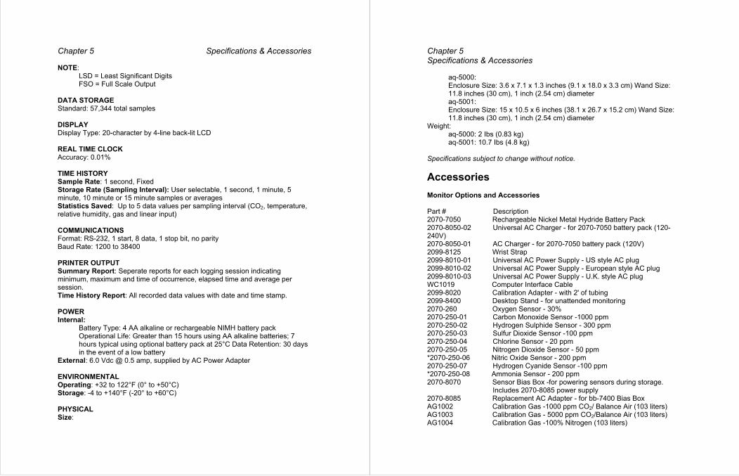
DATA STORAGE Standard: 57,344 total samples DISPLAY Display Type: 20-character by 4-line back-lit LCD REAL TIME CLOCK Accuracy: 0.01%
RY TIME HISTOSample Rate: 1 second, Fixed Storage Rate (Sampling Interval): User selectable, 1 second, 1 minute, 5
or 15 minute samples or averages minute, 10 minuteStatistics Saved: Up to 5 data values per sampling interval (CO2, temperature, relative humidity, gas and linear input) COMMUNICATIONS Format: RS-232, 1 start, 8 data, 1 stop bit, no parity Baud Rate: 1200 to 38400 PRINTER OUTPUT Summary Report: Seperate reports for each logging session indicating minimum, maximum and time of occurrence, elapsed time and average per session. Time History Report: All recorded data values with date and time stamp. POWER Internal:
Battery Type: 4 AA alkaline or rechargeable NIMH battery pack Operational Life: Greater than 15 hours using AA alkaline batteries; 7 hours typical using optional battery pack at 25°C Data Retention: 30 days in the event of a low battery
External: 6.0 Vdc @ 0.5 amp, supplied by AC Power Adapter ENVIRONMENTAL
g: +32 to 122°F (0° to +50°C) OperatinStorage: -4 to +140°F (-20° to +60°C)
SICAL PHYSize:
Chapter 5 Specifications & Accessories
aq-5000: Enclosure Size: 3.6 x 7.1 x 1.3 inches (9.1 x 18.0 x 3.3 cm) Wand Size: 11.8 inches (30 cm), 1 inch (2.54 cm) diameter aq-5001: Enclosure Size: 15 x 10.5 x 6 inches (38.1 x 26.7 x 15.2 cm) Wand Size: 11.8 inches (30 cm), 1 inch (2.54 cm) diameter
Weight: aq-5000: 2 Ibs (0.83 kg) aq-5001: 10.7 Ibs (4.8 kg)
Specifications subject to change without notice.
Accessories Monitor Options and Accessories Part # Description 2070-7050 Rechargeable Nickel Metal Hydride Battery Pack 2070-8050-02 Universal AC Charger - for 2070-7050 battery pack (120-240V) 2070-8050-01 AC Charger2099-8125 Wrist Strap
- for 2070-7050 battery pack (120V)
2099-8010-01 Universal AC Power Supply - US style AC plug 2099-8010-02 Universal AC Power Supply - European style AC2099-8010-03 Universal AC Power Supply - U.K. style AC plug
plug
WC1019 Computer Interface Cable 2099-8020 Calibration Adapter - with 2' of tubing 2099-8400 Desktop Stand - for un2070-260 Oxygen Sensor - 30%
attended monitoring
2070-250-01 Carbon Monoxide Sensor -1000 ppm 2070-250-02 Hydrogen Sulphide Sensor - 3002070-250-03 Sulfur Dioxide Sensor -100 ppm
ppm
2070-250-04 Chlorine Sensor - 20 ppm 2070-250-05 Nitrogen Dioxide Sensor - 50 p*2070-250-06 Nitric Oxide Sensor - 200 ppm
pm
2070-250-07 Hydrogen Cyanide Sensor -100 ppm *2070-250-08 Ammonia Sensor - 200 ppm 2070-8070 Sensor Bias Box -for powering sensors during storage. Includes 2070-8085 power supply 2070-8085 Replacement AC Adapter - for bb-7400 Bias Box AG1002 Calibration Gas -1000 ppm CO2/ Balance Air (103 liters) AG1003 Calibration Gas - 5000 ppm CO /Balance Air (103 liters) 2
AG1004 Calibration Gas -100% Nitrogen (103 liters)

AG1014 Calibration Gas - 35 ppm CO / Balance Air (103 liters) AG1015 Calibration Gas -10 ppm H S / Balance Nitrogen (58 liters) 2
AG1016 Calibration Gas - 5 ppm S0 / Balance Air (58 liters) 2
ers) AG1017 Calibration Gas - 2 ppm CI2/ Balance Nitrogen (58 litAG1011 Calibration Gas - 5 ppm NO / Balance Air (58 liters) 2
AG1013 Calibration Gas - 25 ppm NO / Balance Nitrogen (58 liters) AG1042 Calibration Gas -10 ppm HCN / Balance Nitrogen (58 liters)AG1043 Calibration Gas - 50 ppm NH / Balance Nitrogen (58 liters)
3
987-8030 Calibration Kit - Includes carrying case, regulator, tubing and 1000 ppm CO2& N2 gases
987-8040 Calibration Kit - Includes carrying case, regulator, tubing and 5000 ppm CO & N gases 2 2
AG1009 Regulator - for 58 and 103 liter cylinders. 1 Ipm flow rate, no gauge or valve. AG1005 Regulator - for 58 and 103 liter cylinders. 11pm flow rate with gauge and valve. *Biased sensors: 2070-8070 sensor bias box recommended for maintaining the sensor in a ready state when not attached to the aq-5000/5001.
Chapter 5 Specifications & Accessories Input Cables for Linear Output Sensors/Analyzers Part # Description 2026-9000 Input Cable, Bare Leads 2026-9001 Input Cable, Double Banana Plug 2026-9002 Input Cable, Mini Double Banana Plug 2026-9003 Input Cable, Mini Alligator Clips 2026-9004 Input Cable, Phone Plug (RCA) 2026-9005 Input Cable, Phone Plug, 1/4" Diameter 2026-9006 Input Cable, Mini Phone Plug, 1/8" Diameter 2026-9007 Input Cable, Sub-Mini Phone Plug, 1/16" Diameter 2026-9008 Input Cable, #6 Spade Lugs 2026-9009 Input Cable, Phone Plug 2.5 mm. 2026-9101 Input Cable, Amphenol, 126 S2026-9102 Input Cable, Mini Phone Plug
eries, 5-Pin Connector
2026-9103 Input Cable, Mini Phone Plug w/Resistor 2026-9104 Input Cable, BNC Connector 2026-9105 Input Cable, Amphenol, 126 Series, 5-Pin Connector 2026-9106 Input Cable, 1/16" Phone-Tip Plug (2) 2026-9107 Input Cable, Mini Power Connector2026-9108 Input Cable, Sub-mini Phone Plug
2026-9110 Input Cable, 5-Pin DIN Connector 2026-9111 Input Cable, Amphenol 5-Pin Connector 2026-9112 Input Cable, 4-Pin Switchcraft Connector 2026-9113 Input Cable, 4-Pin Vernitron Connector 2026-9114 Input Cable, Amphenol 5-Pin Connector 2026-9115 Input Cable, 5-Pin DIN Connector 2026-9116 Input Cable, 7-Pin Amphenol Connector 2026-9117 Input Cable, 8-Pin DIN Connector 2026-9203 Input Cable, 2-Pin Lemo Connector 2026-9204 Input Cable, 4-Pin F Lemo B-Series Connector 2026-9205 Input Cable, 4-Pin M Lemo B-Series Connector 2026-9206 Input Cable, 6-Pin F Armaco Connector

Index A Abbreviations 15 AC Power and the Internal Battery 3 -7 Accessories 51-52 B Battery 3 – 7 Battery Pack 5-7 Before You Begin 3 - 8
AC Power and the Internal Battery 3 - 7 Default Recorder Setup 8 Hardware Requirements 3 Selecting Channels 7 - 8 Setting the Real
Biased Sensors 26 Time Clock 7
C Calibrating the CO2 Sensor 9 -11, 21-25 Clearing Data from the IAQ Monitor 13, 45-46 CO , Temperature and Humidity Sensors 21-25 2
Connecting and Calibrating Sensors 21-38 CO , Temperature and Humidity Sensors 21-25 2
Helpful Hints 38 Linear Input Sensor 38 Toxic Gas Sensors 25-37
D Default Recorder Setup 8 Detailed Operating Instructions 15 – 48
Clearing Data from the IAQ Monitor 45 – 46 Connecting and Calibrating SensHelpful Hints 38
ors 21-38
Linear Input Sensor 38 Toxic Gas Sensors 25
Display Abbreviations 15 – 37
Out putting Reports 43 – 44 Secure Mode 47-50 Start and Stop Recording 42 Turning the IAQ Monitor On and Off 19-20 Viewing Information 39 - 41 G Gas Sensors 25 – 37 Getting Started 3 – 8
Index Getting Started with the aq-5000
Before You Begin 3 - 8 AC Power and the Internal Battery 3 - 7 Default Recorder Setup 8 Hardware Requirements 3 Selecting Channels 7 - 8 Setting the Real Time Clock 7
H Hardware Requirements 3 Helpful Hints for Calibrating Sensors 38 L Linear Input Sensor 38 O Output Reports 12, 43 - 44 R Real Time Clock 7 Reports 12 S Secure Mode 47 - 48 Selecting Channels 7 - 8 Sensors 21-38 Specifications 49-50 Start and Stop Recording 11-12, 42 T Toxic Gas Sensors 25 - 37
Biased Sensors 26 Turning the IAQ Monitor On and Off 9, 19 - 20 Tutorial 9 - 13
Calibrating the CO2 Sensor 9 – 11 Clearing Data from the IAQ Monitor 13 Output Reports 12 Start and Stop Recording 11 – 12 Turning the IAQ monitor Viewing Information 11
On and Off 9
V Viewing Information 11, 39 - 41