PVDF Sensor Design and FPGA Implementation of Ultrasound Power Measurement
16
PVDF Sensor Design and FPGA Implementation of Ultrasound Power Measurement Imamul Muttakin, Nur Sabrina Risman, Rania Mahfooz, Dr Hau Yuan Wen, Prof Ir Dr Eko Supriyanto, Dr Nazrul Anuar Nayan, Dr Rosmina Jaafar Universiti Kebangsaan Malaysia, 43600 UKM Bangi, Selangor, Malaysia Universiti Teknologi Malaysia, UTM Skudai, 81300 Johor, Malaysia
-
Upload
ns-risman -
Category
Engineering
-
view
358 -
download
3
Transcript of PVDF Sensor Design and FPGA Implementation of Ultrasound Power Measurement
PVDF Sensor Design and FPGA Implementation of Ultrasound Power
Measurement
Imamul Muttakin, Nur Sabrina Risman, Rania Mahfooz, Dr Hau Yuan Wen, Prof Ir Dr Eko Supriyanto, Dr Nazrul Anuar Nayan, Dr Rosmina Jaafar
Universiti Kebangsaan Malaysia, 43600 UKM Bangi, Selangor, Malaysia
Universiti Teknologi Malaysia, UTM Skudai, 81300 Johor, Malaysia
Outline
• Introduction • Objective• Ultrasound Power Meter System Architecture• Simulations and Discussions• Conclusions
Outline 2
Introduction
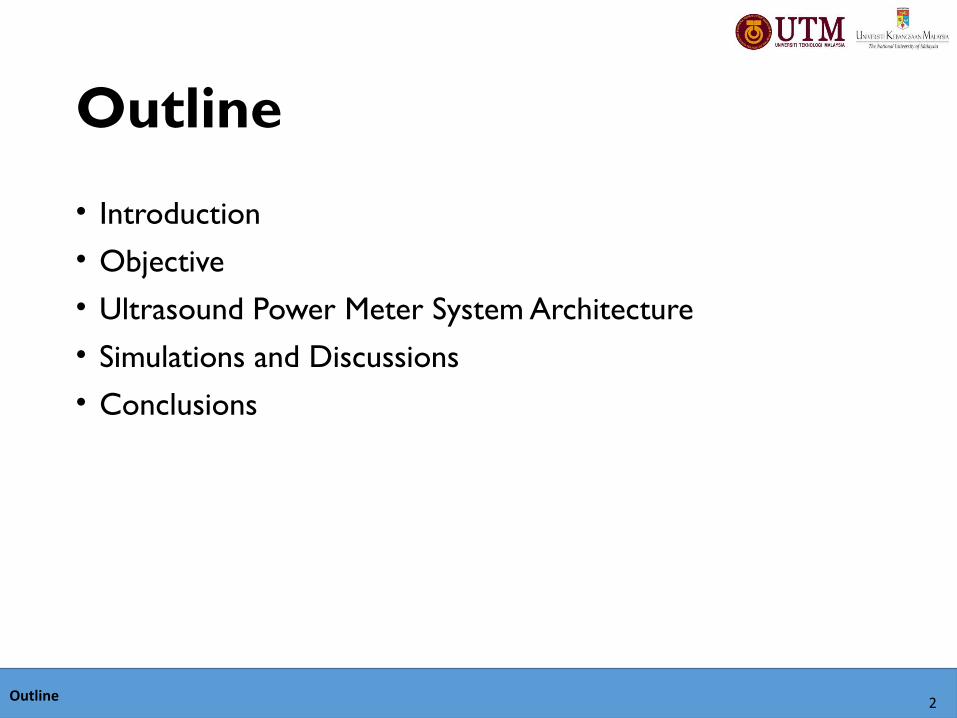
Ultrasound machines
•Widely industrial and medical technology.
•Application in diagnostic and therapeutic uses.
•For diagnostic purpose, ultrasound is safe, painless, method in examining the internals organs that avoids the use of radiation.
•While, therapeutic were starting to emerge almost five decades ago, such as the ability of tissue heating up to some centimetres under the skin.
Introduction 3
Introduction
Introduction 4
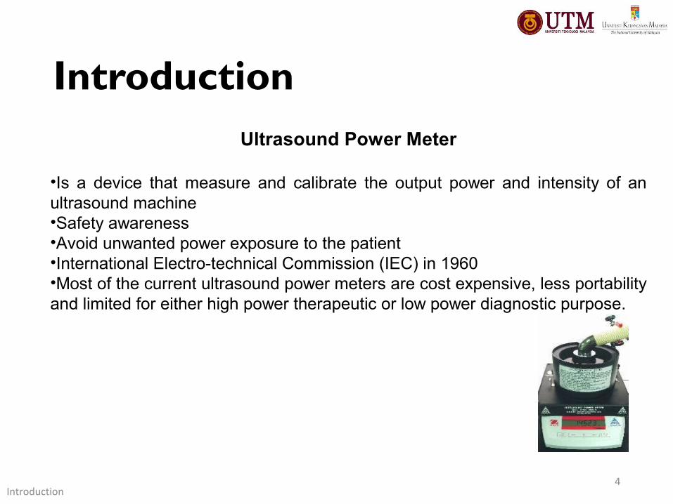
Ultrasound Power Meter
•Is a device that measure and calibrate the output power and intensity of an ultrasound machine•Safety awareness•Avoid unwanted power exposure to the patient•International Electro-technical Commission (IEC) in 1960•Most of the current ultrasound power meters are cost expensive, less portability and limited for either high power therapeutic or low power diagnostic purpose.
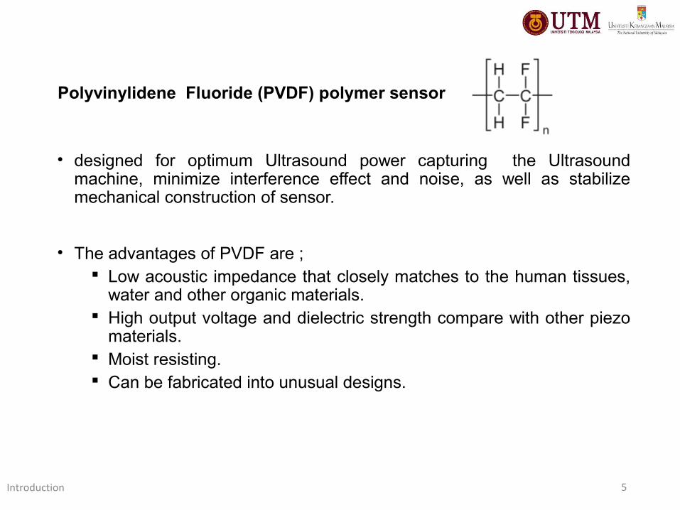
• designed for optimum Ultrasound power capturing the Ultrasound machine, minimize interference effect and noise, as well as stabilize mechanical construction of sensor.
• The advantages of PVDF are ; Low acoustic impedance that closely matches to the human tissues,
water and other organic materials. High output voltage and dielectric strength compare with other piezo
materials. Moist resisting. Can be fabricated into unusual designs.
Introduction 5
Polyvinylidene Fluoride (PVDF) polymer sensor
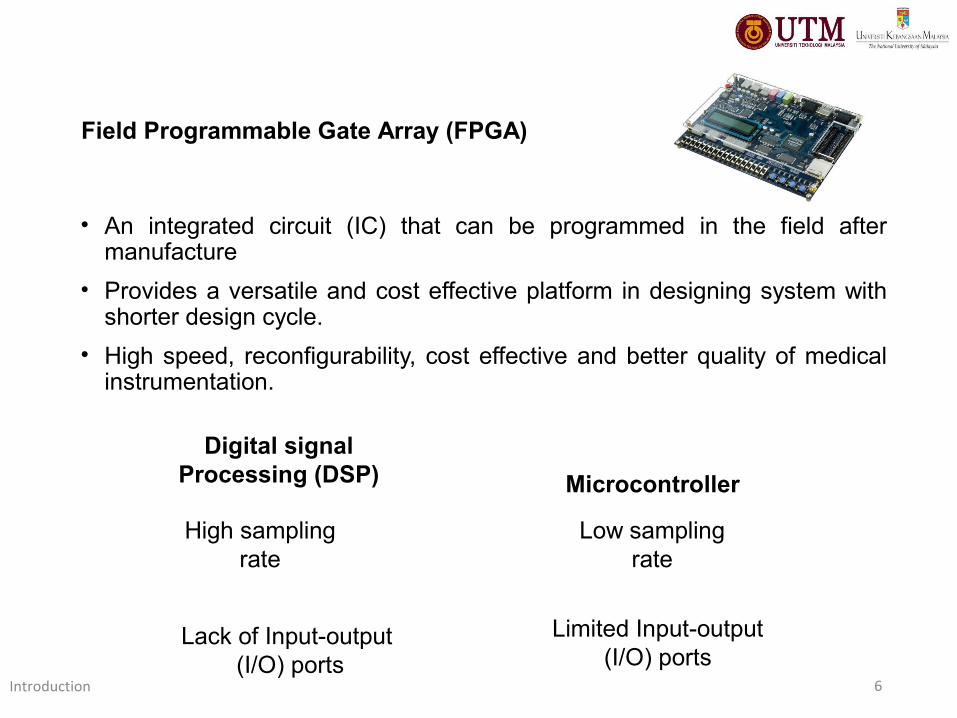
• An integrated circuit (IC) that can be programmed in the field after manufacture
• Provides a versatile and cost effective platform in designing system with shorter design cycle.
• High speed, reconfigurability, cost effective and better quality of medical instrumentation.
Introduction 6
Field Programmable Gate Array (FPGA)
Digital signal Processing (DSP)
High sampling rate
Lack of Input-output (I/O) ports
Microcontroller
Low sampling rate
Limited Input-output (I/O) ports
Objective
• To design an in-house ultrasound power measurement system that should provide the features of compact and simple in construction, able to provide a reliable power measurement results, and user friendly.
Objective 7
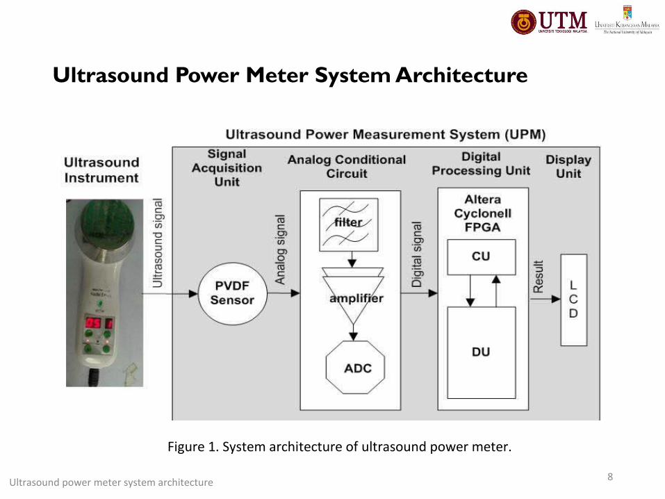
Ultrasound Power Meter System Architecture
Ultrasound power meter system architecture 8
Figure 1. System architecture of ultrasound power meter.
9
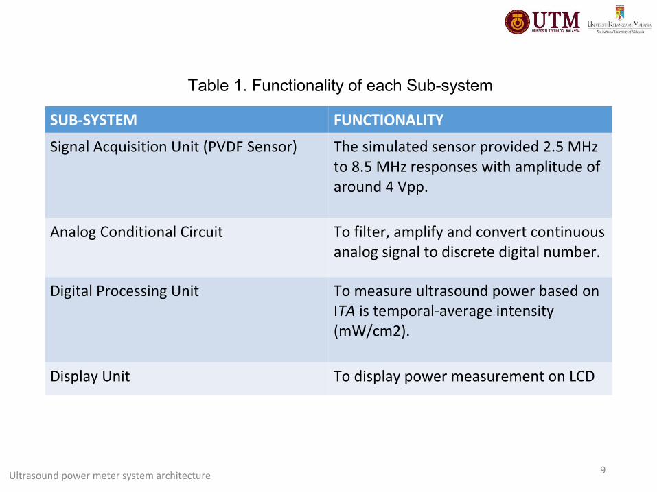
SUB-SYSTEM FUNCTIONALITY
Signal Acquisition Unit (PVDF Sensor) The simulated sensor provided 2.5 MHzto 8.5 MHz responses with amplitude ofaround 4 Vpp.
Analog Conditional Circuit To filter, amplify and convert continuous analog signal to discrete digital number.
Digital Processing Unit To measure ultrasound power based on ITA is temporal-average intensity (mW/cm2).
Display Unit To display power measurement on LCD
Table 1. Functionality of each Sub-system
Ultrasound power meter system architecture
Simulation and Discussions
10
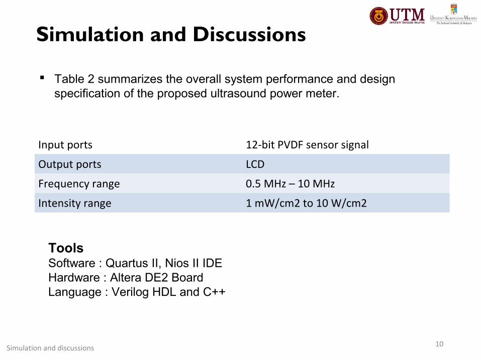
Input ports 12-bit PVDF sensor signal
Output ports LCD
Frequency range 0.5 MHz – 10 MHz
Intensity range 1 mW/cm2 to 10 W/cm2
Table 2 summarizes the overall system performance and design specification of the proposed ultrasound power meter.
Simulation and discussions
Tools Software : Quartus II, Nios II IDEHardware : Altera DE2 BoardLanguage : Verilog HDL and C++
Simulation and Discussions
11
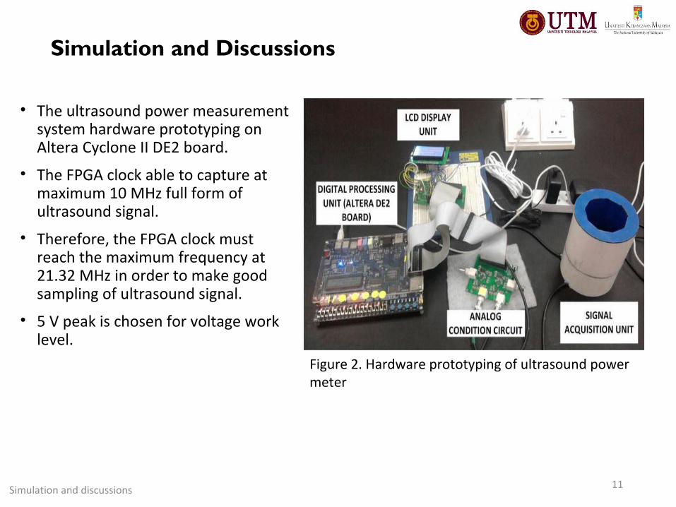
• The ultrasound power measurement system hardware prototyping on Altera Cyclone II DE2 board.
• The FPGA clock able to capture at maximum 10 MHz full form of ultrasound signal.
• Therefore, the FPGA clock must reach the maximum frequency at 21.32 MHz in order to make good sampling of ultrasound signal.
• 5 V peak is chosen for voltage work level.
Figure 2. Hardware prototyping of ultrasound power meter
Simulation and discussions
Simulation and Discussions
12
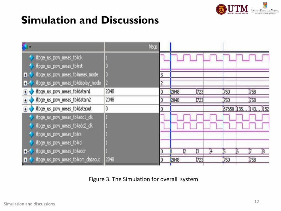
Figure 3. The Simulation for overall system
Simulation and discussions
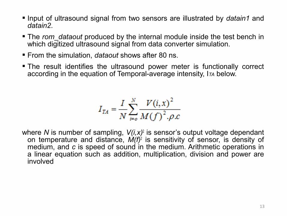
Input of ultrasound signal from two sensors are illustrated by datain1 and datain2.
The rom_dataout produced by the internal module inside the test bench in which digitized ultrasound signal from data converter simulation.
From the simulation, dataout shows after 80 ns.
The result identifies the ultrasound power meter is functionally correct according in the equation of Temporal-average intensity, ITA below.
where N is number of sampling, V(i,x)2 is sensor’s output voltage dependant on temperature and distance, M(f)2 is sensitivity of sensor, is density of medium, and c is speed of sound in the medium. Arithmetic operations in a linear equation such as addition, multiplication, division and power are involved
13

14
Product / Features
Ultrasound Power Meter
UPM-DT-100AV. (Ohmic
Instrument Co.)
Ultrasound Watt Meter UPM
2000 (Netech Biomedical &
Industrial Test Instruments)
Ultrasound Power Meter
– UPM – 30 (Ohm
Instrument Co.)
Proposed Work
Measurement range 0 W to 30 W 0.1 W to 30 W 0 W to 30 W 1 W/cm2 to 50 W/cm2
Frequency range 0.5 MHz to 10 MHz 0.5 MHz to 10 MHz 0.5 MHz to 10 MHz 0.5 MHz to 10 MHz
Ultrasound test media Degassed water Degassed water Degassed water Normal water or
ultrasound gel
Resolution 200mW 0.1 W 150m W 0.003 mW/cm2
Power source 12 VAC,500 mA power
adapter
9 V - 15V
Sensor - - - PVDF
Ultrasound Applications - - - Diagnostic and
therapeutics
Display 3-Digit LCD LCD - LCD
Communication
Interface
RS-232 RS-232 RS-232 USB
Table 3. Comparison of This proposed work with other product.
Simulation and discussions
Conclusion
• This paper has presented an in-house ultrasound power measurement system with a low cost, user friendly and high precision capability suitable for medical application.
• The unique design has been obtained while the test results show a possibility to use it for an ultrasound intensity measurement purpose.
• In future for further modification towards an ultrasound, digital processing unit is desired to improve the overall system performance. Hence support the real time analysis and optimizing hardware area (e.g. reducing logic element).
Conclusion15

Thank You
16