Publication No. 80/P – Non-destructive Testing – 2014
52
PRZEPISY RULES PUBLIKACJA NR 80/P PUBLICATION NO. 80/P BADANIA NIENISZCZĄCE NON-DESTRUCTIVE TESTING 2014 styczeń/January Publikacje P (Przepisowe) wydawane przez Polski Rejestr Statków są uzupełnieniem lub rozszerzeniem Przepisów i stanowią wymagania obowiązujące tam, gdzie mają zastosowanie. Publications P (Additional Rule Requirements) issued by Polski Rejestr Statków complete or extend the Rules and are mandatory where applicable. GDAŃSK
Transcript of Publication No. 80/P – Non-destructive Testing – 2014
PRZEPISY RULES
PUBLIKACJA NR 80/P PUBLICATION NO. 80/P
BADANIA NIENISZCZĄCE
NON-DESTRUCTIVE TESTING
2014 styczeń/January
Publikacje P (Przepisowe) wydawane przez Polski Rejestr Statków są uzupełnieniem lub rozszerzeniem Przepisów i stanowią wymagania obowiązujące tam, gdzie mają zastosowanie.
Publications P (Additional Rule Requirements) issued by Polski Rejestr Statków complete or extend the Rules and are mandatory where applicable.
GDAŃSK


PRZEPISY RULES
PUBLIKACJA NR 80/P PUBLICATION NO. 80/P
BADANIA NIENISZCZĄCE
NON-DESTRUCTIVE TESTING
2014 styczeń/January
GDAŃSK

Publikacja Nr 80/P – Badania nieniszczące – 2014, stanowi rozszerzenie wymagań Części I – Zasady klasyfikacji i Części IX – Materiały i spawanie, Przepisów klasyfikacji i budowy statków morskich.
Publikacja ta została zatwierdzona przez Zarząd PRS S.A. w dniu 31 grudnia 2013 r. i wchodzi w życie z dniem 1 stycznia 2014 r.
Publikacja Nr 80/P – Badania nieniszczące – 2014 zastępuje Publikację Nr 80/P – Badania nieniszczące, edycja 2011.
Publication No. 80/P – Non-destructive Testing – 2014, is an extension of the requirements contained in Part I – Classification Regulations and Part IX – Materials and Welding of the Rules for the Classification and Construction of Sea-going Ships.
The present Publication was approved by the PRS Board on 31 December 2014 and enters into force on 1 January 2014.
Publication No. 80/P – Non-destructive Testing – 2014 replaces Publication No. 80/P – Non-destructive Testing – 2011.
© Copyright by Polski Rejestr Statków, 2014
PRS/OP, 01/2014
ISBN 978-83-7664-155-3
SPIS TREŚCI str.
1 Postanowienia ogólne ................................................................................................... 5 1.1 Zakres zastosowania .............................................................................................. 5 1.2 Określenia i definicje ............................................................................................. 8 1.3 Normy powołane w Publikacji .............................................................................. 8
2 Metody badań nieniszczących ................................................................................... 11 2.1 Postanowienia ogólne .......................................................................................... 11 2.2 Badania wizualne (VT) ........................................................................................ 11 2.3 Badania penetracyjne (PT) .................................................................................. 12 2.4 Badania magnetyczno-proszkowe (MT) .............................................................. 13 2.5 Badania radiograficzne (RT) ............................................................................... 14 2.6 Badania ultradźwiękowe (UT) ............................................................................. 15 2.7 Badania prądami wirowymi (ET) ........................................................................ 17 2.8 Badania szczelności (LT) .................................................................................... 17
3 Zakres badań nieniszczących .................................................................................... 17 3.1 Postanowienia ogólne .......................................................................................... 17 3.2 Zakres badań nieniszczących złączy spawanych kadłuba statku ......................... 18 3.3 Zakres badań nieniszczących złączy spawanych kotłów, zbiorników
ciśnieniowych i wymienników ciepła .................................................................. 22 3.4 Zakres badań nieniszczących złączy spawanych rurociągów .............................. 23 3.5 Zakres badań nieniszczących złączy spawanych elementów mechanizmów
i urządzeń oraz innych konstrukcji ...................................................................... 23 4 Kryteria oceny ............................................................................................................ 23
4.1 Postanowienia ogólne .......................................................................................... 23 4.2 Poziomy akceptacji/jakości złączy spawanych kadłuba statku ............................ 24 4.3 Poziomy akceptacji/jakości złączy spawanych kotłów, zbiorników
ciśnieniowych i wymienników ciepła .................................................................. 26 4.4 Poziomy akceptacji/jakości złączy spawanych rurociągów ................................. 26 4.5 Poziomy akceptacji/jakości złączy spawanych elementów mechanizmów
i urządzeń oraz innych konstrukcji ...................................................................... 27

CONTENTS Page
1 General ........................................................................................................................ 29
1.1 General Provisions ............................................................................................... 29 1.2 Definitions ........................................................................................................... 32 1.3 Normative References .......................................................................................... 32
2 Non-destructive Testing Methods ............................................................................. 35 2.1 General ................................................................................................................. 35 2.2 Visual Testing (VT) ............................................................................................. 35 2.3 Penetrant Testing (PT) ......................................................................................... 36 2.4 Magnetic-particle Testing (MT) ........................................................................... 36 2.5 Radiographic Testing (RT) .................................................................................. 38 2.6 Ultrasonic Testing (UT) ....................................................................................... 38 2.7 Eddy-current Testing (ET) ................................................................................... 40 2.8 Leak-tightness Testing (LT) ................................................................................ 40
3 Scope of Non-destructive Testing ............................................................................ 40 3.1 General ................................................................................................................. 40 3.2 Scope of Non-destructive Testing of Welded Joints in Ship’s Hull ..................... 41 3.3 Scope of Non-destructive Testing of Welded Joints in Boilers,
Pressure Vessels and Heat Exchangers ................................................................ 45 3.4 Scope of Non-destructive Testing of Welded Joints in Piping ............................ 46 3.5 Scope of Non-destructive Testing of Welded Joints in Components
of Machinery, Equipment and Other Structures .................................................. 46 4 Assessment Criteria .................................................................................................. 46
4.1 General ................................................................................................................. 46 4.2 Acceptance/Quality Levels of Welded Joints in Ship’s Hull ............................... 47 4.3 Acceptance/Quality Levels of Welded Joints in Boilers, Pressure Vessels
and Heat Exchangers ........................................................................................... 49 4.4 Acceptance/Quality Levels of Welded Joints in Piping ....................................... 49 4.5 Acceptance/Quality Levels of Welded Joints in Elements of Machinery,
Arrangements and Other Structures ..................................................................... 50

1 POSTANOWIENIA OGÓLNE
1.1 Zakres zastosowania
1.1.1
1.1.2
1.1.3
Wymagania niniejszej Publikacji mają zastosowanie we wszystkich przy-padkach, gdy w Przepisach wymagane są badania nieniszczące a nie podano szczegółowych wymagań dotyczących takich badań, lub gdy dokumentacja tech-niczna nie precyzuje takich wymagań.
Niniejsza Publikacja nie obejmuje wymagań związanych z badaniami: − złączy egzaminacyjnych spawaczy; wymagania dotyczące takich badań podane
są w Publikacji 3/P – Zasady egzaminowania spawaczy, − złączy spawanych zbiorników ładunkowych gazu skroplonego i technologi-
cznych zbiorników ciśnieniowych na gazowcach; wymagania dotyczące takich badań podane są w Publikacji 48/P – Wymagania dla gazowców,
− odkuwek stalowych; wymagania dotyczące takich badań podane są w Publikacji 70/P – Badania nieniszczące odkuwek stalowych stosowanych na elementy kadłuba i urządzeń maszynowych,
− odlewów staliwnych; wymagania dotyczące takich badań podane są w Publikacji 71/P – Badania nieniszczące odlewów stalowych stosowanych na elementy kadłuba,
− płyt próbnych podczas kwalifikacji technologii spawania; wymagania dotyczące tych badań podane są w Publikacji 74/P – Zasady kwalifikowania technologii spawania.
Wymagania zawarte w przywołanych w niniejszej Publikacji normach i innych dokumentach należy traktować jako wymagania niniejszej Publikacji. Oznaczenia i tytuły norm wraz z datą ich wydania (aktualną w momencie wydawania niniejszej Publikacji) podane są w rozdziale 1.3. W praktyce zaleca się stosowanie aktualnych wydań powołanych dokumentów.
Niniejsza Publikacja określa wymagania dotyczące badania i oceny materiałów, wyrobów metalowych i złączy spawanych z zastosowaniem kilku lub jednej z metod badań nieniszczących, wymienionych niżej: − wizualnej (VT), − penetracyjnej (PT), − magnetyczno-proszkowej (MT), − radiograficznej (RT), − ultradźwiękowej (UT), − prądów wirowych (ET), − sprawdzenia szczelności (LT).
Wybór metody badań zależy od położenia i rodzaju spodziewanych niezgodności oraz dostępu do obszaru lub odcinka badania.
5

1.1.4
1.1.5
1.1.6
1.1.7
1.1.8
1.1.9
Laboratorium wykonujące badania nieniszczące określone w 1.1.3 powinno być uznane przez PRS, zgodnie z zasadami podanymi w Publikacji Nr 56/P – Zasady uznawania laboratoriów.
Badania mogą być wykonywane tylko przez operatorów kwalifikowanych i certyfikowanych, w odpowiednim sektorze przemysłowym i sektorze wyrobu. Certyfikacja powinna być zgodna z wymaganiami normy PN-EN 473. Możliwość wykonywania badań przez operatorów z uprawnieniami nadanymi zgodnie z innymi systemami certyfikacji personelu (np. ISO 9712) podlega odrębnemu rozpatrzeniu przez PRS.
Procedury badań nieniszczących powinny być zatwierdzone przez personel posiadający uprawnienia 3. stopnia w odpowiednim sektorze przemysłowym i sektorze wyrobu. Certyfikacja powinna być zgodna z wymaganiami normy PN-EN 473. Możliwość zatwierdzania procedur badań przez operatorów z uprawnieniami nadanymi zgodnie z innymi systemami certyfikacji personelu (np. ISO 9712) podlega odrębnemu rozpatrzeniu przez PRS. Procedury badań nieniszczących powinny być przedstawione PRS do uzgodnienia przed rozpoczęciem badań.
Zakres badań nieniszczących i wymagany poziom akceptacji lub jakości powinny być podane w dokumentacji technicznej wyrobu np. Planie badań nieniszczących lub w dokumentacji wykonawczej konstrukcji spawanej np. Planie badań nieniszczących złączy spawanych. Dokumentacja techniczna wyrobu lub Plan badań nieniszczących, dokumentacja wykonawcza konstrukcji spawanej lub Plan badań nieniszczących złączy spawanych podające zakres badań nieniszczących podlegają uzgodnieniu z PRS.
Wykryte niezgodności, które nie są akceptowalne należy naprawić w uzgodnieniu z PRS, a miejsca naprawione ponownie poddać badaniom. Zakres badania po wykonanej naprawie obejmuje obszar naprawianej niezgodności i min. 100 mm od jego końców. Protokoły z badań po naprawie należy przedstawić inspektorowi PRS wraz z dokumentami z badań przed naprawą.
Z przeprowadzonych badań nieniszczących powinien być sporządzony protokół, w którym niezależnie od metody badania należy podać co najmniej: − nazwę laboratorium wykonującego badania, − datę badania i numer protokołu badania, − identyfikację badanego obiektu (np. gatunek materiału, grubość materiału, typ
spoiny, proces spawania), − jednoznaczną identyfikację miejsca badania, − kryteria akceptacji (np. poziom jakości lub poziom akceptacji), − procedurę badania (np. nr normy lub procedury), − wyposażenie i materiały dodatkowe stosowane do badań wraz z parametrami
badania (patrz p. 1.1.10),
6

− wszelkie ograniczenia podczas badań oraz warunki otoczenia, np. temperaturę powietrza, wilgotność, temperaturę konstrukcji,
− wynik badania wraz z określeniem wielkości i lokalizacji stwierdzonych niezgodności,
− stwierdzenie o spełnieniu lub niespełnieniu wymagań, − imię, nazwisko i podpis oraz poziom uprawnień operatora wykonującego badania.
W protokole z badań należy przywołać numer Świadectwa uznania wydanego przez PRS, datę jego wystawienia i ważności.
Jeśli badanie przeprowadzono po naprawie, to informacja ta powinna być zawarta w protokole. Należy również podać numer protokołu z badania przed naprawą.
1.1.10 W protokole z badań należy podać następujące informacje dotyczące wyposażenia i materiałów użytych do badania daną metodą:
dla badań penetracyjnych (PT): − nazwa i typ penetranta, zmywacza, wywoływacza, − czasy penetracji i wywoływania, − temperaturę badania, − warunki obserwacji (np: rodzaj i natężenie światła);
dla badań magnetyczno-proszkowych (MT): − sposób magnesowania, − natężenie pola magnetycznego, − rodzaj środka wykrywającego, − warunki obserwacji (np: rodzaj i natężenie światła), − informację o demagnetyzacji, jeżeli jest wymagana;
dla badań radiograficznych (RT): − rodzaj i wielkość źródła promieniowania, − rodzaj filmu, − rodzaj okładek wzmacniających, − technikę badania, czas ekspozycji i odległość od źródła promieniowania, − czułość badania, typ i położenie wskaźnika, − gęstość radiogramu, − nieostrość geometryczną;
dla badań ultradźwiękowych (UT): − rodzaj i identyfikację użytej głowicy, − rodzaj zastosowanego środka sprzęgającego, − nastawiony poziom czułości dla każdej głowicy, − wielkości korekty zastosowanych wzmocnień, − rodzaj wzorca, − wielkość wzmocnienia zastosowaną do badań.
7

1.1.11 Protokoły z przeprowadzonych badań powinny być przechowywane przez laboratorium minimum przez 5 lat, licząc od daty przekazania wyrobu lub konstrukcji spawanej do eksploatacji.
1.2 Określenia i definicje
O d l e g ł o ś c i o w a k o r e k c j a a m p l i t u d y (OKA) – ang. Distance Amplitude Correction (DAC). O d l e g ł o ś ć - w z m o c n i e n i e - r o z m i a r (OWR) – ang. Distance Gain Size (DGS) – niem. AVG-method. W s k a ź n i k j a k o ś c i o b r a z u – Image Quality Indicator (IQI). N i e z g o d n o ś ć – wykrywalna nieciągłość materiału lub jego zmiana powstała w sposób naturalny lub sztuczny. O b s z a r b a d a n i a – obszar wyrobu, na jakim jest prowadzone badanie nieniszczące. O d c i n e k b a d a n i a – odcinek złącza spawanego, na jakim jest prowadzone badanie nieniszczące; dla badań penetracyjnych, magnetyczno-proszkowych i ultradźwiękowych należy przyjąć minimalną długość 500 mm, dla badań radiograficznych należy przyjąć standardową długość radiogramu 480 mm (minimalna długość radiogramu: 300 mm). P l a n b a d a ń n i e n i s z c z ą c y c h / P l a n b a d a ń n i e n i s z c z ą c y c h z ł ą c z y s p a w a n y c h – dokument zawierający co najmniej następujące informacje: usytuowanie obszarów lub odcinków badania, zastosowaną metodę badania, poziom akceptacji, jednoznaczny sposób oznaczania poszczególnych obszarów lub odcinków badania i sposób ich oznaczania po naprawie oraz poziom jakości wyrobu lub konstrukcji spawanej. Dokument ten powinien podawać również informacje o firmie, która będzie wykonywać badania nieniszczące tj. nazwę firmy i numer Świadectwa uznania przez PRS.
P r o c e d u r a b a d a ń – dokument podający sposób postępowania przy wykonywaniu badań.
Inne definicje związane z badaniami nieniszczącymi zawarte są w serii norm słownikowych związanych z badaniami nieniszczącymi.
1.3 Normy powołane w Publikacji
Ogólne:
PN-EN 473:2008 – Badania nieniszczące – Kwalifikacja i certyfikacja personelu badań nieniszczących – Zasady ogólne. ISO 9712:2005 – Non-destructive testing – Qualification and certification of personnel.
8

PN-EN ISO 5817:2009 – Spawanie – Złącza spawane stali, niklu, tytanu i ich stopów (z wyłączeniem spawania wiązką) – Poziomy jakości według niezgodności spawalniczych. PN-EN ISO 6520-1:2009 – Spawanie i procesy pokrewne – Klasyfikacja geometrycznych niezgodności spawalniczych w metalach – Część 1: Spawanie. PN-EN ISO 10042:2008 – Spawanie – Złącza spawane łukowo w aluminium i jego stopach – Poziomy jakości według niezgodności spawalniczych. PN-EN ISO 17635:2010 – Badania nieniszczące złączy spawanych – Zasady ogólne dotyczące metali.
Badania wizualne (VT):
PN-EN 970:1999 – Spawalnictwo – Badania nieniszczące złączy spawanych –Badania wizualne. PN-EN 13018:2004 – Badania nieniszczące – Badania wizualne – Zasady ogólne. PN-EN 13927:2009 – Badania nieniszczące – Badania wizualne – Wyposażenie. PN-ISO 3058:2001 – Badania nieniszczące – Przyrządy pomocnicze do badań wizualnych – Dobór lup o małych powiększeniach.
Badania penetracyjne (PT):
PN-EN 571-1:1999 – Badania nieniszczące – Badania penetracyjne – Zasady ogólne. PN-EN ISO 3059:2005 – Badania nieniszczące – Badania penetracyjne i badania magnetyczno-proszkowe – Warunki obserwacji. PN-EN ISO 3452-2:2006 – Badania nieniszczące – Badania penetracyjne – Część 2: Badania materiałów penetracyjnych. PN-EN ISO 3452-3:2001 – Badania nieniszczące – Badania penetracyjne – Część 3: Próbki odniesienia. PN-EN ISO 23277:2010 – Badania nieniszczące spoin – Badania penetracyjne spoin – Poziomy akceptacji.
Badania magnetyczno-proszkowe (MT):
PN-EN ISO 3059:2005 – Badania nieniszczące – Badania penetracyjne i badania magnetyczno-proszkowe – Warunki obserwacji. PN-EN ISO 9934-1:2005 – Badania nieniszczące – Badania magnetyczno-proszkowe – Część 1: Zasady ogólne. PN-EN ISO 9934-2:2003 – Badania nieniszczące – Badania magnetyczno-proszkowe – Część 2: Środki wykrywające. PN-EN ISO 9934-3:2003 – Badania nieniszczące – Badania magnetyczno-proszkowe – Część 3: Aparatura. PN-EN ISO 17638:2010 – Badania nieniszczące spoin – Badania magnetyczno-proszkowe. PN-EN ISO 23278:2010 – Badania nieniszczące spoin – Badania magnetyczno-proszkowe spoin – Poziomy akceptacji.
9

Badania radiograficzne (RT):
PN-EN 444:1998 – Badania nieniszczące – Ogólne zasady radiograficznych badań materiałów metalowych za pomocą promieniowania X i gamma. PN-EN 462-1:1998 – Badania nieniszczące – Jakość obrazu radiogramów – Wskaźniki jakości obrazu (typu pręcikowego) – Liczbowe wyznaczanie jakości obrazu. PN-EN 462-2:1998 – Badania nieniszczące – Jakość obrazu radiogramów – Wskaźniki jakości obrazu (typu schodkowo-otworkowego) – Liczbowe wyznaczanie jakości obrazu. PN-EN-584-1:2009 – Badania nieniszczące – Błona radiograficzna przemysłowa – Część 1: Klasyfikacja systemów błony dla radiografii przemysłowej. PN-EN 1435:2001 – Badania nieniszczące złączy spawanych – Badania radiograficzne złączy spawanych. PN-EN 12517-1:2008 – Badania nieniszczące spoin – Część 1: Ocena złączy spawanych ze stali, niklu, tytanu i ich stopów na podstawie radiografii – Poziomy akceptacji. PN-EN 13068-3:2002 – Badania nieniszczące – Badania radiologiczne – Część 3: Ogólne zasady radiologicznych badań materiałów metalowych za pomocą promieniowania X i gamma. PN-EN 25580:1997 – Badania nieniszczące – Przemysłowe negatoskopy radiograficzne – Wymagania minimalne.
Badania ultradźwiękowe (UT):
PN-EN 583-1:2001 – Badania nieniszczące – Badania ultradźwiękowe – Część 1: Zasady ogólne. PN-EN 583-2:2004 – Badania nieniszczące – Badania ultradźwiękowe – Część 2: Nastawianie czułości i zakresu obserwacji. PN-EN 583-3:2000 – Badania nieniszczące – Badania ultradźwiękowe – Technika przepuszczania. PN-EN 583-4:2003 – Badania nieniszczące – Badania ultradźwiękowe – Część 4: Badania nieciągłości prostopadłych do powierzchni. PN-EN 583-5:2005 – Badania nieniszczące – Badania ultradźwiękowe – Część 5: Charakteryzowanie i wymiarowanie nieciągłości. PN-EN 583-6:2009 – Badania nieniszczące – Badania ultradźwiękowe – Część 6: Dyfrakcyjna technika czasu przejścia jako sposób wykrywania i wymiarowania nieciągłości. PN-EN 10160:2001 – Badanie ultradźwiękowe wyrobów stalowych płaskich o grubości równej lub większej niż 6 mm (metoda echa). PN-EN 10307:2004 – Badania nieniszczące – Badanie ultradźwiękowe wyrobów płaskich ze stali nierdzewnych austenitycznych i austenityczno-ferrytycznych o grubości równej lub większej niż 6 mm (metoda odbicia). PN-EN 12223:2003 – Badania nieniszczące – Badania ultradźwiękowe – Opis próbki wzorcowej nr 1.
10

PN-EN 12668-1:2010 – Badania nieniszczące – Charakteryzowanie i weryfikacja aparatury ultradźwiękowej – Część 1: Aparatura. PN-EN 12668-2:2010 – Badania nieniszczące – Charakteryzowanie i weryfikacja aparatury ultradźwiękowej – Część 2: Głowice. PN-EN 12668-3:2003 – Badania nieniszczące – Charakteryzowanie i weryfikacja aparatury ultradźwiękowej – Część 3: Aparatura kompletna. PN-EN 27963:1993 – Połączenia spawane stali – Wzorzec kontrolny nr 2 do ultradźwiękowych badań stali. PN-EN ISO 11666:2011 – Badania nieniszczące spoin – Badania ultradźwiękowe złączy spawanych – Poziomy akceptacji. PN-EN ISO 17640:2011 – Badania nieniszczące spoin – Badania ultradźwiękowe złączy spawanych.
Badania wiroprądowe (ET):
PN-EN ISO 15549:2011 – Badania nieniszczące – Badania metodą prądów wirowych – Zasady ogólne.
Badania szczelności (LT):
PN-EN 1779:2002 – Badania nieniszczące – Badania szczelności – Kryteria wyboru metody i techniki.
2 METODY BADAŃ NIENISZCZĄCYCH
2.1 Postanowienia ogólne
2.1.1
2.1.2
2.1.3
2.2.1
2.2.2
Stan powierzchni powinien umożliwiać przeprowadzenie badań nieniszczących. Powierzchnia przygotowana do badań powinna być sucha i wolna od zanieczyszczeń takich jak: zendra, żużel, produkty korozji, itp. oraz powłok lakierniczych.
W trakcie prowadzenia badań nieniszczących należy zapewnić właściwe warunki badań, zgodne z wymaganiami podanymi w normach przedmiotowych.
Zastępowanie badań radiograficznych badaniami ultradźwiękowymi i odwrot-nie jest dopuszczalne w ramach zakresu ich zastosowania dla spoin czołowych z pełnym przetopem o grubości większej niż 10 mm i po uzgodnieniu tego faktu z PRS.
2.2 Badania wizualne (VT)
Procedura badań wizualnych powinna zawierać: sposób przygotowania powierzchni, warunki badania, sposób stosowania wyposażenia pomocniczego.
Badania wizualne powinny obejmować 100% powierzchni badanych wyrobów, długości złączy spawanych i mogą być wykonywane jako badania wizualne bezpośrednie i/lub zdalne.
11

2.2.3
2.2.4
2.2.5
2.2.6
2.2.7
2.2.8
2.3.1
2.3.2
2.3.3
2.3.4
Badania wizualne złączy spawanych mogą być wykonywane przez wyznaczony personel nadzoru spawalniczego posiadający odpowiednie uprawnienia, zgodnie z wymaganiami podanymi w p. 1.1.5.
Badania wizualne należy wykonywać przed wykonaniem innych badań nieniszczących. Pozytywny wynik badań wizualnych pozwala na wykonanie dalszych badań nieniszczących.
Badania wizualne materiałów i wyrobów należy prowadzić zgodnie z wymaganiami normy PN-EN 13018, a badania złączy spawanych zgodnie z wymaganiami normy PN-EN 970.
Wyposażenie pomocnicze stosowane do badań wizualnych powinno spełniać wymagania normy PN-EN 13927, a zastosowane do badań lupy o małym powiększeniu powinny spełniać wymagania normy PN-ISO 3058.
Przy badaniach wizualnych bezpośrednich minimalna odległość między okiem operatora a badaną powierzchnią powinna się mieścić w granicach do 600 mm przy kącie widzenia nie mniejszym niż 30°.
Minimalne natężenie oświetlenia przy badaniach wizualnych, mierzone na badanej powierzchni, powinno wynosić 500 lx.
2.3 Badania penetracyjne (PT)
Procedura badań penetracyjnych powinna zawierać: sposób przygotowania powierzchni, przypadki wymagające przygotowania próbek odniesienia, warunki wykonywania badania (np: zakres temperatur) i warunki obserwacji, typ zestawu badawczego, sposób nanoszenia poszczególnych odczynników zestawu, czas penetracji i wywoływania.
Badania penetracyjne materiałów, wyrobów i złączy spawanych należy prowadzić zgodnie z wymaganiami normy PN-EN 571-1. Zestaw preparatów stosowanych do badań penetracyjnych powinien pochodzić od jednego producenta i powinien posiadać oznaczenia zgodnie z wymaganiami normy PN-EN ISO 3452-2. Oceny zestawu penetrantów należy dokonać na próbce odniesienia typu 2, zgodnej z normą PN-EN ISO 3452-3.
Temperatura badanego obiektu mierzona na jego powierzchni powinna zawierać się w zakresie 10 ÷ 50 °C. Przeprowadzanie badań w innych temperaturach możliwe jest po wcześniejszym uzgodnieniu z PRS.
Penetrant można nanosić na badaną powierzchnię dowolną metodą, należy jednak zapewnić, aby badana powierzchnia była pokryta penetrantem podczas całego czasu penetracji. Czas penetracji nie powinien być krótszy niż 10 min.
12

2.3.5
2.3.6
2.3.7
2.4.1
2.4.2
2.4.3
2.4.4
2.4.5
2.4.6
Czas wywoływania powinien zawierać się w zakresie 10 ÷ 30 min. Pierwszą kontrolę wskazań należy przeprowadzić bezpośrednio po nałożeniu wywoływacza, kontrolę końcową wskazań po zakończeniu czasu wywoływania. Zaleca się przeprowadzenie przynajmniej jednej kontroli pośredniej w trakcie czasu wywoływania. Do protokołu należy wpisywać wszystkie wskazania zaobserwowane w trakcie kontroli końcowej.
Natężenie oświetlenia, mierzone na powierzchni badania, powinno dla metody barwnej wynosić co najmniej 500 lx. W przypadku stosowania penetrantów fluorescencyjnych w pomieszczeniach zamkniętych natężenie oświetlenia otoczenia obiektu badanego nie powinno być większe niż 20 lx. Natężenie napromieniowania UV-A powinno być większe niż 10 W/m2, ale w żadnym przypadku nie powinno przekraczać 50 W/m2. Szczegółowe wymagania związane z warunkami obserwacji wskazań przy prowadzeniu badań penetracyjnych podaje norma PN-EN ISO 3059.
Jeżeli istnieją podejrzenia, że nieciągłości powierzchni zostały zatarte na skutek czyszczenia mechanicznego, to dalsze postępowanie należy uzgodnić z PRS.
2.4 Badania magnetyczno-proszkowe (MT)
Procedura badań magnetyczno-proszkowych powinna zawierać: sposób przygotowania powierzchni, sposób przygotowania wzorców, sposób magneso-wania, warunki obserwacji, rodzaj stosowanej zawiesiny, sposób jej nanoszenia i przypadki wymagające przeprowadzenia demagnetyzacji.
Badania magnetyczno-proszkowe materiałów i wyrobów należy prowadzić zgodne z wymaganiami normy PN-EN ISO 9934-1, a badania złączy spawanych zgodnie z wymaganiami normy PN-EN ISO 17638.
Wyposażenie stosowane do badań magnetyczno-proszkowych powinno spełniać wymagania normy PN-EN ISO 9934-3.
Natężenie wzbudzonego pola magnetycznego na powierzchni badanego obiektu powinno być większe od 2 kA/m.
Środki wykrywające stosowane przy badaniach magnetyczno-proszko-wych mogą mieć postać suchego proszku lub ciekłej zawiesiny i powinny spełniać wymagania normy PN-EN ISO 9934-2.
Przy stosowaniu zawiesiny magnetycznej do identyfikacji wskazań należy tak długo utrzymywać w badanym elemencie pole magnetyczne, aż większość cieczy będącej nośnikiem zawiesiny spłynie z badanej powierzchni, co zapobiegnie rozmyciu wskazań.
13

2.4.7
2.4.8
2.4.9
2.4.10
2.4.11
2.4.12
2.5.1
2.5.2
W celu poprawy kontrastu między powierzchnią badaną a środkami wykrywającymi dopuszczalne jest zastosowanie cienkiej, jednolitej powłoki lakierniczej. Ściśle przylegające powłoki nieferromagnetyczne (np. lakiernicze) o grubości do 50 μm nie powodują zmniejszenia czułości badania i nie muszą być usuwane.
Badanie danego obszaru powinno być przeprowadzone z dwóch wzajemnie prostopadłych kierunków magnesowania. Maksymalne odchylenie od prostopadłości kierunków magnesowania może wynosić 30°.
Natężenie oświetlenia, mierzone na powierzchni badania, powinno wynosić co najmniej 500 lx. W przypadku stosowania penetrantów fluorescencyjnych w pomieszczeniach zamkniętych natężenie oświetlenia otoczenia obiektu badanego nie powinno być większe niż 20 lx. Natężenie napromieniowania UV-A powinno być większe niż 10 W/m2. Szczegółowe wymagania związane z warunkami obserwacji wskazań przy prowadzeniu badań magnetyczno-proszkowych podaje norma PN-EN ISO 3059.
Po zakończonych badaniach magnetyczno-proszkowych należy wszędzie tam, gdzie jest to wymagane, przeprowadzić rozmagnesowanie badanego elementu do wymaganego poziomu.
W przypadku badań elementów obrabianych maszynowo (np. kół zębatych, wałów, itp.) należy sprawdzić, czy nie zachodzi konieczność rozmagnesowania wstępnego, w przypadku gdy element poddany badaniom posiada magnetyzm szczątkowy z poprzednich operacji technologicznych.
Podczas przeprowadzania badań magnetyczno-proszkowych wyrobu gotowego lub powierzchni po obróbce końcowej należy zwrócić szczególną uwagę na sposób magnesowania, tak aby nie uszkodzić tego wyrobu lub powierzchni.
2.5 Badania radiograficzne (RT)
Procedura badań radiograficznych powinna zawierać: rodzaj zastosowanego źródła promieniowania, dobór parametrów badania w zależności od badanej grubości, układ badania oraz sposób ułożenia błony, rodzaj i sposób ułożenia wskaźnika jakości obrazu (IQI), wymaganą jakość radiogramu, typ zastosowanej błony i okładek wzmacniających (jeżeli są wymagane), sposób kontroli promieniowania rozproszonego, proces wywoływania, gęstość radiogramu i sposób obserwacji.
Badania radiograficzne materiałów i wyrobów metalowych należy prowadzić zgodne z wymaganiami normy PN-EN 444 lub PN-EN 13068-3, a badania złączy spawanych zgodnie z wymaganiami normy PN-EN 1435.
14

2.5.3
2.5.4
2.5.5
2.5.6
2.5.7
2.5.8
2.6.1
2.6.2
Wyposażenie stosowane do badań radiograficznych powinno być co najmniej raz w roku sprawdzane przez zakład serwisowy, który powinien pisemnie potwierdzić zgodność parametrów wyposażenia z wymaganymi warunkami technicznymi.
Wymaganie to nie zwalnia użytkownika od prowadzenia bieżącej kontroli wyposażenia.
Badania radiograficzne należy wykonywać promieniami X. Badania promieniami γ mogą być stosowane wyłącznie po wcześniejszym uzgodnieniu z PRS.
Do badań radiograficznych należy stosować przemysłowe błony radiograficzne spełniające wymagania normy PN-EN 584-1. Dobór błon radiograficznych do badań zależy od klasy badania, grubości badanego obiektu oraz zastosowanego źródła promieniowania. Zastosowanie cyfrowego zapisu radiogramów wymaga uzgodnienia z PRS.
Do określania jakości radiogramów zaleca się stosować następujące wskaźniki jakości obrazu (IQI): pręcikowe spełniające wymagania normy PN-EN 462-1 lub schodkowo-otworkowe spełniające wymagania normy PN-EN 462-2.
Gęstość radiogramu powinna wynosić minimum 2 dla klasy A oraz 2,3 dla klasy B. Górna wartość gęstości zależy od parametrów negatoskopu, na którym prowadzona jest ocena.
Ocenę radiogramów należy prowadzić w zaciemnionych pomieszczeniach z wykorzystaniem negatoskopu z regulowaną luminancją. Negatoskop powinien spełniać wymagania normy PN-EN 25580.
2.6 Badania ultradźwiękowe (UT)
Procedura badań ultradźwiękowych powinna zawierać: informacje o defektoskopie, stosowanych głowicach (częstotliwość, kąt głowicy), rodzaj sprzęgacza, stosowane wzorce, sposób nastawiania czułości badania, sposób wyznaczenia strat przeniesienia, sposób przeszukiwania, sposób sprawdzania poprawności nastaw w trakcie badania.
Badania ultradźwiękowe materiałów i wyrobów należy prowadzić zgodnie z wymaganiami normy PN-EN 583, arkusze od 1 do 5, badanie elementów płaskich o grubości od 6 mm zgodnie z wymaganiami normy PN-EN 10160 lub PN-EN 10307. Badania ultradźwiękowe złączy spawanych o grubości większej niż 8 mm należy prowadzić zgodnie z wymaganiami normy PN-EN ISO 17640. Badania ultradźwiękowe odkuwek, odlewów i rur spawanych należy prowadzić zgodnie z wymaganiami odpowiednich norm związanych. Badania ultradźwiękowe metodą TOFD należy prowadzić zgodnie z wymaganiami normy PN-EN 583-6, prowadzenie tych badań wymaga uzgodnienia z PRS.
15

2.6.3
2.6.4
2.6.5
2.6.6
2.6.7
2.6.8
2.6.9
2.6.10
2.6.11
Wyposażenie stosowane do badań ultradźwiękowych powinno spełniać wymagania normy PN-EN 12668-1. Powinno być ono co najmniej raz w roku sprawdzane przez zakład serwisowy, który powinien pisemnie potwierdzić zgodność parametrów wyposażenia z wymaganymi warunkami technicznymi.
Wymaganie to nie zwalnia użytkownika od prowadzenia bieżącej kontroli układu defektoskop – głowica zgodnie z wymaganiami normy PN-EN 12668-3.
W badaniach ultradźwiękowych należy stosować głowice o częstotliwości 2 ÷ 5 MHz, które powinny spełniać wymagania normy PN-EN 12668-2. Dobór głowicy uzależniony jest od: − grubości materiału, kształtu i stanu powierzchni, − rodzaju i warunków metalurgicznych badanego obiektu, − rodzaju, położenia i kierunku spodziewanych niezgodności.
Dla głowic kątowych kąt głowicy i położenie jej środka należy kontrolować na początku i po zakończeniu badania oraz w trakcie badania, gdy istnieje podejrzenie zmiany tych parametrów.
Do ustawienia czułości badania PRS zaleca metodę OWR (ang. DGS). Do nastawiania poziomu odniesienia należy stosować okrągłe reflektory tarczowe DSR o średnicach podanych w normie PN-EN ISO 11666.
Do nastawienia układu defektoskop – głowica należy posługiwać się próbką wzorcową nr 1, spełniającą wymagania normy PN-EN 12223 i/lub wzorcem kontrolnym nr 2, spełniającym wymagania normy PN-EN 27963.
Dla zapewnienia przejścia fali ultradźwiękowej z głowicy do badanego obiektu należy stosować środki sprzęgające np: żel do badań ultradźwiękowych lub inne posiadające jednorodną strukturę (np: olej, smar, roztwór kleju do tapet).
Powierzchnia w miejscu przesuwu głowicy powinna umożliwiać swobodny przesuw głowicy oraz zapewniać stałe warunki sprzężenia akustycznego, tak aby miejscowe różnice nie przekraczały +/– 2 dB.
Przed przystąpieniem do badania złącza spawanego należy zbadać obszar przesuwu głowicy kątowej. Badanie to należy przeprowadzić za pomocą głowicy prostej.
W przypadku stwierdzenia niezgodności, badanie złącza spawanego przy pomocy głowicy kątowej należy przeprowadzić z innego obszaru przesuwu głowicy kątowej, w którym nie stwierdzono niezgodności.
Podczas badania złączy spawanych głowicą kątową należy stosować skanowanie zapewniające co najmniej 10% pokrycie obszarów przesuwu głowicy.
Zalecanym przez PRS systemem oceny wykrytych niezgodności jest system oparty na metodzie OWR (ang. DGS). Jako inna metoda do określenia
16

niezgodności może być stosowana metoda DAC. Do określania wielkości niezgod-ności liniowych należy stosować technikę 6 dB spadku. Jeśli ma być stosowany inny system oceny niezgodności, to należy przedstawić PRS jego opis w celu akceptacji.
2.7 Badania prądami wirowymi (ET)
2.7.1
2.7.2
2.8.1
2.8.2
3.1.1
3.1.2
3.1.3
3.1.4
Metodę badania prądami wirowymi należy stosować do badania materiałów i wyrobów ferromagnetycznych i nieferromagnetycznych. Umożliwia ona wykrywanie niezgodności wewnętrznych i powierzchniowych poprzez wykorzystanie efektu naskórkowości.
Badania prądami wirowymi materiałów i wyrobów należy prowadzić zgodnie z wymaganiami normy PN-EN ISO 15549.
2.8 Badania szczelności (LT)
Badania szczelności złączy spawanych należy przeprowadzać podczas prób gotowych konstrukcji, wg wymagań zawartych w odpowiednich częściach Przepisów PRS.
W przypadku kiedy Przepisy PRS nie podają metody badania szczelności, należy stosować wymagania normy PN-EN 1779.
3 ZAKRES BADAŃ NIENISZCZĄCYCH
3.1 Postanowienia ogólne
Zakres badań nieniszczących dla materiałów i wyrobów powinien być określony w dokumentacji technicznej wyrobu, np. Planie badań nieniszczących.
Zakres badań nieniszczących złączy spawanych powinien być określony w dokumentacji wykonawczej konstrukcji spawanej, np. Planie badań nieniszczących złączy spawanych. Badaniom należy poddać głównie złącza spawane wykonywane podczas montażu. W złączu spawanym badaniu podlega spoina oraz 10 mm strefa przy spoinie lub strefa wpływu ciepła, w zależności która wielkość jest większa. Ogólne zasady doboru badań nieniszczących do badania złączy spawanych podaje norma PN-EN ISO 17635.
PRS zastrzega sobie prawo do rozszerzenia wcześniej uzgodnionego zakresu badań nieniszczących oraz równoległych badań kilkoma metodami w zależności od bieżącej oceny jakości wykonanej pracy.
Po zakończeniu prac związanych z wykonaniem wyrobu lub prac spawalniczych na danej konstrukcji, służby kontroli wykonawcy powinny zaznaczyć miejsca badań nieniszczących (obszary badania/odcinki badania), zgodnie z uzgodnioną dokumentacją.
17

3.1.5
3.1.6
3.1.7
Badania nieniszczące wyrobu lub konstrukcji można wykonać dopiero po zakończeniu spawania lub obróbki cieplnej (jeżeli jest wymagana) i ostygnięciu do temperatury otoczenia.
Badania nieniszczące złączy spawanych ze stali wysokiej wytrzymałości o granicy plastyczności ReH ≥ 420 MPa można wykonać dopiero po upływie minimum 48 godzin od zakończenia spawania. Jeżeli przewidziana jest obróbka cieplna wyrobu lub konstrukcji, to badania można przeprowadzić najwcześniej po 48 godzinach od zakończenia obróbki.
Zakład wykonujący konstrukcje spawane jest zobowiązany, co najmniej raz na sześć miesięcy, określić współczynnik jakości złączy spawanych na podstawie odcinków badania dla badań radiograficznych i ultradźwiękowych oraz przedstawić te wyniki inspektorowi PRS na jego życzenie. Współczynnik jakości złączy spawanych należy obliczyć według wzoru:
%100DlK = (3.1.7)
K – współczynnik jakości złączy spawanych, [%]; l – łączna długość odcinków badania dla badań radiograficznych i ultradźwięk-
kowych, na których wykryto niezgodności spawalnicze, które nie są akceptowalne, [m];
D – łączna długość wszystkich odcinków badania dla badań radiograficznych i ultradźwiękowych, [m].
Jeżeli współczynnik jakości złączy spawanych przekracza 10%, to za każdy 1% powyżej tej liczby PRS może wymagać zwiększenia liczby odcinków badania o 5%. Liczba odcinków badania może zostać ponownie zmniejszona, gdy zakład podejmie działania korygujące i inspektor PRS uzna poziom prac spawalniczych za zadowalający.
3.2 Zakres badań nieniszczących złączy spawanych kadłuba statku
3.2.1 Zakres badań nieniszczących złączy spawanych poszycia i elementów usztywnień kadłuba statku o długości L > 24 m powinien być podany w Planie badań nieniszczących złączy spawanych i być opracowany w oparciu o wytyczne podane w tabeli 3.2.1.
Liczbę odcinków badania dla rejonu 0,4L środkowej części statku należy określać według wzoru:
45
)( HBLN += (3.2.1)
N – liczba odcinków badania dla badań radiograficznych i ultradźwiękowych, B – szerokość statku, [m], H – wysokość statku, [m],
18
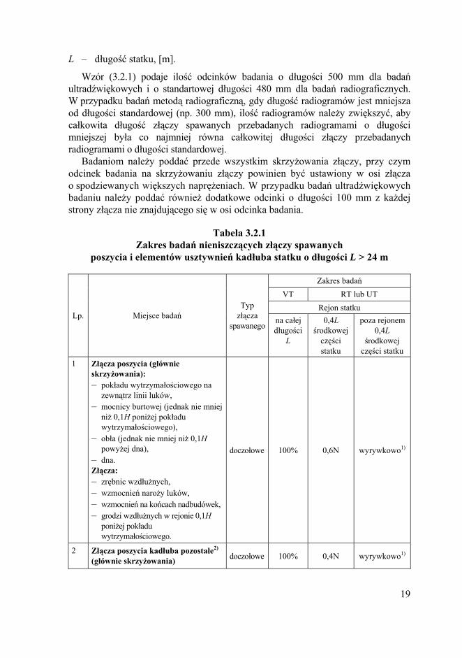
L – długość statku, [m].
Wzór (3.2.1) podaje ilość odcinków badania o długości 500 mm dla badań ultradźwiękowych i o standartowej długości 480 mm dla badań radiograficznych. W przypadku badań metodą radiograficzną, gdy długość radiogramów jest mniejsza od długości standardowej (np. 300 mm), ilość radiogramów należy zwiększyć, aby całkowita długość złączy spawanych przebadanych radiogramami o długości mniejszej była co najmniej równa całkowitej długości złączy przebadanych radiogramami o długości standardowej.
Badaniom należy poddać przede wszystkim skrzyżowania złączy, przy czym odcinek badania na skrzyżowaniu złączy powinien być ustawiony w osi złącza o spodziewanych większych naprężeniach. W przypadku badań ultradźwiękowych badaniu należy poddać również dodatkowe odcinki o długości 100 mm z każdej strony złącza nie znajdującego się w osi odcinka badania.
Tabela 3.2.1 Zakres badań nieniszczących złączy spawanych
poszycia i elementów usztywnień kadłuba statku o długości L > 24 m
Zakres badań VT RT lub UT
Rejon statku Lp. Miejsce badań
Typ złącza
spawanego na całejdługości
L
0,4L środkowej
części statku
poza rejonem 0,4L
środkowej części statku
1 Złącza poszycia (głównie skrzyżowania): – pokładu wytrzymałościowego na
zewnątrz linii luków, – mocnicy burtowej (jednak nie mniej
niż 0,1H poniżej pokładu wytrzymałościowego),
– obła (jednak nie mniej niż 0,1H powyżej dna),
– dna. Złącza: – zrębnic wzdłużnych, – wzmocnień naroży luków, – wzmocnień na końcach nadbudówek, – grodzi wzdłużnych w rejonie 0,1H
poniżej pokładu wytrzymałościowego.
doczołowe 100% 0,6N wyrywkowo1)
2 Złącza poszycia kadłuba pozostałe2) (głównie skrzyżowania) doczołowe 100% 0,4N wyrywkowo1)
19

Zakres badań VT RT lub UT
Rejon statku Lp. Miejsce badań
Typ złącza
spawanego na całejdługości
L
0,4L środkowej
części statku
poza rejonem 0,4L
środkowej części statku
3 Złącza usztywnień wzdłużnych (zładu wzdłużnego): – pokładu wytrzymałościowego na
zewnątrz linii luków, – mocnicy burtowej (jednak nie mniej
niż 0,1H poniżej pokładu wytrzymałościowego),
– obła (jednak nie mniej niż 0,1H powyżej dna),
– dna, – grodzi wzdłużnych w rejonie 0,1H
poniżej pokładu wytrzymałościowego
doczołowe 100%
1 odcinek badania na każde 5 złączy (głównie złącza montażowe)
wyrywkowo1)
4 Złącza usztywnień wzdłużnych pozostałe
doczołowe 100%
1 odcinek badania na
każde 10 złączy (głównie
złącza montażowe
)
wyrywkowo1)
5 Złącza usztywnień poprzecznych (zładu poprzecznego): doczołowe 100%
1 odcinek badania na
każde 10 złączy
wyrywkowo1)
6 Złącze mocnicy pokładowej z mocnicą burtową kątowe
ze spoiną czołową
100%
4 odcinki badania na długości jednego arkusza blachy3)
wyrywkowo 1), 3)
1) Liczba odcinków badania nie powinna przekraczać 35% odcinków badania dla odpowiednich grup konstrukcyjnych, podanych dla rejonu 0,4L w środkowej części statku.
2) W przypadku istnienia wzmocnień lodowych należy badać głównie złącza pasa lodowego. 3) Zaleca się stosowanie badań ultradźwiękowych.
3.2.2 Zakres badań nieniszczących złączy spawanych poszycia i elementów usztywnień kadłuba statku o długości L ≤ 24 m i statków śródlądowych powinien być podany w Planie badań nieniszczących złączy spawanych. Badaniom należy
20

poddać głównie miejsca badania wymienione w tabeli 3.2.1. Zakres badania tj. ilość odcinków badania i ich umiejscowienie podlega odrębnemu rozpatrzeniu przez PRS.
3.2.3 Oprócz elementów konstrukcji kadłuba określonych w tabeli 3.2.1 lub wymagań p. 3.2.2, badaniom nieniszczącym należy poddać złącza spawane na połączeniu elementów wyposażenia z konstrukcją kadłuba statku w tabeli 3.2.3. Rozmieszczenie miejsc badań nieniszczących tych złączy należy uzgodnić z inspektorem PRS.
Tabela 3.2.3 Zakres badań nieniszczących złączy spawanych
na połączeniu elementów wyposażenia z konstrukcją kadłuba statku
Zakres badań w % Lp. Miejsce badania
VT PT/MT/RT/UT1) 1 2 3 4 1 Połączenie kadłuba i pochwy wału śrubowego 100 100 2 Połączenie kadłuba i elementów zawieszenia steru 100 100 3 Połączenia kadłuba i wspornika wału śrubowego 100 100 4 Połączenie kadłuba i tunelu steru strumieniowego 100 50 5 Połączenia kadłuba z fundamentami silników głównych 100 20 6 Połączenia kadłuba z fundamentami silników pomocniczych 100 20 7 Połączenia kadłuba z fundamentami urządzeń dźwignicowych 100 20 8 Połączenia kadłuba z fundamentami masztów 100 20 9 Połączenia kadłuba z fundamentami maszyn i urządzeń 100 20
1) Wybór metody badania jest zależny od typu spoiny badanego złącza spawanego.
3.2.4
3.2.5
Na statkach do przewozu kontenerów należy wykonać badania ultra-dźwiękowe wszystkich połączeń międzyblokowych wszystkich wzdłużnych elementów konstrukcyjnych górnej części przekroju poprzecznego kadłuba w rejonie ładunkowym. Do tych elementów zalicza się: najwyższy pas poszycia kadłuba wewnętrznego/grodzi wzdłużnej, mocnicę burtową, pokład główny, płyty zrębnicy luku, górną płytę zrębnicy oraz wszystkie usztywnienia wzdłużne określone na rys. 3.2.4.
Zakres badań nieniszczących złączy spawanych kadłuba statku w trakcie przebudowy lub remontu należy każdorazowo uzgodnić z PRS. Zakres ten zależny jest od zakresu przebudowy lub prowadzonego remontu.
21
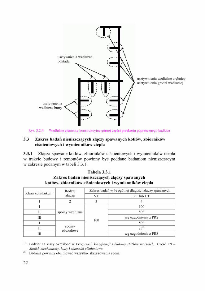
Rys. 3.2.4 Wzdłużne elementy konstrukcyjne górnej części przekroju poprzecznego kadłuba
usztywnienia wzdłużne pokładu
usztywnienia wzdłużne zrębnicy usztywnienia grodzi wzdłużnej
usztywnienia wzdłużne burty
3.3 Zakres badań nieniszczących złączy spawanych kotłów, zbiorników ciśnieniowych i wymienników ciepła
3.3.1 Złącza spawane kotłów, zbiorników ciśnieniowych i wymienników ciepła w trakcie budowy i remontów powinny być poddane badaniom nieniszczącym w zakresie podanym w tabeli 3.3.1.
Tabela 3.3.1 Zakres badań nieniszczących złączy spawanych
kotłów, zbiorników ciśnieniowych i wymienników ciepła
Zakres badań w % ogólnej długości złączy spawanych Klasa konstrukcji1) Rodzaj
złącza VT RT lub UT 1 2 3 4 I 100 II 502) III
spoiny wzdłużne wg uzgodnienia z PRS
I 502) II 252) III
spoiny obwodowe
100
wg uzgodnienia z PRS
1) Podział na klasy określono w Przepisach klasyfikacji i budowy statków morskich, Część VII –Silniki, mechanizmy, kotły i zbiorniki ciśnieniowe.
2) Badania powinny obejmować wszystkie skrzyżowania spoin.
22

3.4 Zakres badań nieniszczących złączy spawanych rurociągów
3.4.1 Złącza spawane rurociągów powinny być poddane badaniom nieniszczącym w zakresie podanym w tabeli 3.4.1.
Tabela 3.4.1 Zakres badań nieniszczących połączeń spawanych rurociągów
Zakres badań w % złączy spawanych Klasa rurociągu1)
Średnica zewnętrzna rury
[mm] VT MT2) RT lub UT
1 2 3 4 5 ≤ 75 100 103)
I > 75 100 100
≤ 100 wyrywkowo wyrywkowo II
> 100 103) 103)
III niezależnie od średnicy
100
wyrywkowo wyrywkowo
1) Podział na klasy określono w Przepisach klasyfikacji i budowy statków morskich, Część VII –Silniki, mechanizmy, kotły i zbiorniki ciśnieniowe.
2) Spoiny pachwinowe łączące kołnierz z rurą. 3) Jednak nie mniej niż jedno złącze wykonane przez danego spawacza.
3.4.2
3.5.1
4.1.1
W rurociągach klasy I spoiny pachwinowe połączeń kołnierzowych powinny być poddane badaniom magnetyczno-proszkowym.
3.5 Zakres badań nieniszczących złączy spawanych elementów mechanizmów i urządzeń oraz innych konstrukcji
Zakres badań nieniszczących złączy spawanych elementów mechanizmów i urządzeń oraz innych konstrukcji niż przedstawione w niniejszej Publikacji powinien być podany w dokumentacji technicznej. Ilość miejsc badania będzie odrębnie rozpatrywana przez PRS.
Badaniom należy poddać przede wszystkim silnie obciążone węzły elementów mechanizmów i urządzeń oraz innych konstrukcji.
4 KRYTERIA OCENY
4.1 Postanowienia ogólne
Wymagany poziom jakości powinien być określony w dokumentacji:
− technicznej materiału, wyrobu, np. Planie badań nieniszczących, − wykonawczej konstrukcji spawanej, np. Planie badań nieniszczących złączy
spawanych.
23

Szczegółowe poziomy jakości materiałów, wyrobów lub złączy spawanych podają Przepisy PRS. W przypadku gdy takie wymagania nie zostały określone, to należy stosować normy dotyczące danego wyrobu.
4.1.2
4.1.3
4.1.4
4.1.5
4.2.1
Stwierdzone niezgodności należy klasyfikować i opisywać zgodnie z postanowieniami normy PN-EN ISO 6520-1.
Poziom jakości złączy spawanych dla wyrobów wykonanych ze stali należy określić według normy PN-EN ISO 5817, a dla wyrobów wykonanych z aluminium lub jego stopów według normy PN-EN ISO 10042.
Wytyczne dotyczące poziomu akceptacji i poziomu jakości złączy spawanych dla poszczególnych metod badań podaje norma PN-EN ISO 17635. W przypadku badań wizualnych poziomy jakości są tożsame z poziomami akceptacji. Dla pozostałych metod badań poziomy akceptacji należy określać wg norm odpowiednich dla danej metody badania: – PN-EN ISO 23277 dla PT, – PN-EN ISO 23278 dla MT, – PN-EN 12517-1 dla RT, – PN-EN ISO 11666 dla UT.
W metodach badań wizualnej (VT), penetracyjnej (PT) i magnetyczno-proszkowej (MT) nie określa się poziomu techniki badań.
4.2 Poziomy akceptacji/jakości złączy spawanych kadłuba statku
Poziomy akceptacji/jakości złączy spawanych poszycia i elementów usztywnień kadłuba dla statków o długości L > 24 m, w zależności od ich miejsca, przedstawiono w tabeli 4.2.1.
Tabela 4.2.1 Poziom jakości i poziom akceptacji złączy spawanych
poszycia i elementów usztywnień kadłuba dla statków o długości L > 24 m
w rejonie 0,4L poza rejonem 0,4L Metoda badania Poziom
jakości Poziom
akceptacji Poziom jakości
Poziom akceptacji
1 2 3 4 5 Wizualna (VT) B B C C Penetracyjna (PT) B 2X C 2X Magnetyczno-proszkowa (MT) B 2X C 2X Radiograficzna (RT) B 1 C 2 Ultradźwiękowa (UT) B 2 C 3
24

4.2.2
4.2.3
Poziomy akceptacji/jakości złączy spawanych poszycia i elementów usztywnień kadłuba dla statków o długości L > 24 m niższe niż podane w tabeli 4.2.1 będą odrębnie rozpatrywane przez PRS.
Poziomy akceptacji/jakości złączy spawanych poszycia i elementów usztywnień kadłuba dla statków o długości L ≤ 24 m i statków śródlądowych przedstawiono w tabeli 4.2.3.
Tabela 4.2.3 Poziom jakości i poziom akceptacji złączy spawanych poszycia i elementów
usztywnień kadłuba dla statków o długości L ≤ 24 m i statków śródlądowych Metoda badania Poziom jakości Poziom akceptacji
1 2 3 Wizualna (VT) C C Penetracyjna (PT) C 2X Magnetyczno-proszkowa (MT) C 2X Radiograficzna (RT) C 2 Ultradźwiękowa (UT) C 3
4.2.4
4.2.5
Poziomy akceptacji/jakości złączy spawanych poszycia i elementów usztywnień kadłuba dla statków o długości L ≤ 24 m niższe niż podane w tabeli 4.2.3 będą odrębnie rozpatrywane przez PRS.
Poziomy akceptacji/jakości złączy spawanych na połączeniu elementów wyposażenia z konstrukcją kadłuba statku podano w tabeli 4.2.5.
Tabela 4.2.5 Poziomy akceptacji/jakości złączy spawanych
na połączeniu elementów wyposażenia z konstrukcją kadłuba
Poziom akceptacji Lp. Miejsce badania
VT PT MT RT UT Poziom jakości
1 2 3 4 5 6 7 8 1 Połączenie poszycia kadłuba i pochwy
wału śrubowego B 1 1 1 2 B
2 Połączenie poszycia kadłuba i elementów zawieszenia steru B 1 1 1 2 B
3 Połączenia poszycia i wspornika wału śrubowego B 1 1 1 2 B
4 Połączenie poszycia i tunelu steru strumieniowego B 1 1 1 2 B
5 Połączenia kadłuba z fundamentami silników głównych B 1 1 1 2 B
6 Połączenia kadłuba z fundamentami silników pomocniczych C 2X 2X 2 3 C
25

1 2 3 4 5 6 7 8 7 Połączenia kadłuba z fundamentami
urządzeń dźwignicowych B 1 1 1 2 B
8 Połączenia kadłuba z fundamentami masztów C 2X 2X 2 3 C
9 Połączenia kadłuba z fundamentami maszyn i urządzeń C 2X 2X 2 3 C
4.2.6
4.3.1
Poziomy akceptacji/jakości złączy spawanych na połączeniu elementów wyposażenia z konstrukcją kadłuba statku niższe niż podane w tabeli 4.2.5 będą odrębnie rozpatrywane przez PRS.
4.3 Poziomy akceptacji/jakości złączy spawanych kotłów, zbiorników ciśnieniowych, wymienników ciepła
Poziomy akceptacji/jakości złączy spawanych kotłów, zbiorników ciśnieniowych, wymienników ciepła, w zależności od ich klasy, podano w tabeli 4.3.1.
Tabela 4.3.1 Poziomy akceptacji/jakości złączy spawanych kotłów,
zbiorników ciśnieniowych i wymienników ciepła w zależności od ich klasy1)
klasa I klasa II klasa III Metoda badania Poziom
jakości Poziom
akceptacji Poziom jakości
Poziom akceptacji
Poziom jakości
Poziom akceptacji
Wizualna (VT) B B C C C C Penetracyjna (PT) B 1 C 2X C 2X Magnetyczno-proszkowa (MT) B 1 C 2X C 2X Radiograficzna (RT) B 1 C 2 C 2 Ultradźwiękowa (UT) B 2 C 3 C 3
1) Podział na klasy określono w Przepisach klasyfikacji i budowy statków morskich, Część VII – Silniki, mechanizmy, kotły i zbiorniki ciśnieniowe.
4.3.2
4.4.1
Poziomy akceptacji/jakości złączy spawanych kotłów, zbiorników ciśnieniowych i wymienników ciepła niższe niż wymienione w tabeli 4.3.1 będą odrębnie rozpatrywane przez PRS. Poziom jakości D jest niedopuszczalny dla kotłów, zbiorników ciśnieniowych i wymienników ciepła klasy I.
4.4 Poziomy akceptacji/jakości złączy spawanych rurociągów
Poziomy akceptacji/jakości złączy spawanych rurociągów, w zależności od ich klasy, podano w tabeli 4.4.1.
26

Tabela 4.4.1 Poziomy akceptacji/jakości złączy spawanych
rurociągów w zależności od ich klasy1)
klasa I klasa II klasa III Metoda badania Poziom
jakości Poziom
akceptacji Poziom jakości
Poziom akceptacji
Poziom jakości
Poziom akceptacji
1 2 3 4 5 6 7 Wizualna (VT) B B C C C C Penetracyjna (PT) B 1 C 2X C 2X Magnetyczno-proszkowa (MT) B 1 C 2X C 2X Radiograficzna (RT) B 1 C 2 C 2 Ultradźwiękowa (UT) B 2 C 3 C 3
1) Podział na klasy określono w Przepisach klasyfikacji i budowy statków morskich, Część VII –Silniki, mechanizmy, kotły i zbiorniki ciśnieniowe.
4.4.2
4.5.1
Poziomy akceptacji/jakości rurociągów niższe niż wymienione w tabeli 4.4.1 będą odrębnie rozpatrywane przez PRS. Poziom jakości D jest niedopuszczalny dla rurociągów klasy I.
4.5 Poziomy akceptacji/jakości złączy spawanych elementów mechanizmów i urządzeń oraz innych konstrukcji
Poziomy akceptacji/jakości złączy spawanych elementów mechanizmów i urządzeń oraz innych konstrukcji niż przedstawione w niniejszej Publikacji powinny być podane w dokumentacji technicznej i będą odrębnie rozpatrywane przez PRS.
27

NON-DESTRUCTIVE TESTING

1 GENERAL
1.1 General Provisions
1.1.1
1.1.2
1.1.3
The requirements of the present Publication apply to all cases where non-destructive testing is required by the Rules and no specific requirements for the tests are given therein or where such requirements are not defined in technical documentation.
This Publication does not cover requirements for the testing of: − welder test pieces; the relevant requirements are specified in Publication
No. 3/P – Principles for Examination of Welders, − welded joints of liquefied gas cargo tanks and process pressure vessels in gas
tankers; the relevant requirements are specified in Publication No. 48/P – Requirements Concerning Gas Tankers,
− steel forgings; the relevant requirements are specified in Publication No. 70/P – Non-destructive Testing of Hull and Machinery Steel Forgings,
− steel castings; the relevant requirements are specified in Publication No. 71/P – Non-destructive Testing of Hull Marine Steel Castings,
− test assemblies made for the purposes of welding procedure qualification tests; the relevant requirements are specified in Publication No. 74/P – Principles for Welding Procedure Qualification Tests.
The present Publication refers to the provisions of other documents (e.g. standards). The provisions, through reference to this text, constitute the requirements of this Publication. Notations and titles of the standards, together with the date of their issue (current at the time of the present Publication issue), are specified in sub-chapter 1.3. It is recommended that current editions of the reference documents should be used.
The present Publication specifies the requirements for the testing and assessment of metallic materials and products, as well as welded joints using one or several non-destructive methods, listed below, i.e.: − visual testing (VT), − penetrant testing (PT), − magnetic-particle testing (MT), − radiographic testing (RT), − ultrasonic testing (UT), − eddy-current testing (ET), − leak tightness testing (LT).
The selection of a testing method depends on location and type of anticipated imperfections, as well as access to the tested area or test segment.
29

1.1.4
1.1.5
1.1.6
1.1.7
1.1.8
1.1.9
The laboratory performing non-destructive tests, specified in 1.1.3, shall be approved by PRS in accordance with the principles set forth in Publication No. 56/P – Procedural Requirements for Laboratories.
Non-destructive tests may be performed only by operators qualified and certified in the relevant industrial sector and product sector. Certification shall be in accordance with the requirements specified in EN 473. The possibility of carrying out the tests by operators qualified according to other personnel certification schemes (e.g. standard ISO 9712) is subject to special consideration of PRS.
Non-destructive-testing procedures shall be approved by personnel certified to level 3 in the relevant industrial sector and product sector. Certification shall be in accordance with the requirements specified in EN 473. The possibility of non-destructive testing procedures approval by personnel qualified according to other certification schemes (e.g. standard ISO 9712) is subject to special consideration of PRS. Non-destructive testing procedures shall be agreed with PRS before the commencement of the tests.
The extent of non-destructive testing and the required acceptance or quality level shall be specified in the product technical documentation, e.g. Non-destructive Testing Plan or in the workshop documentation of a welded structure, e.g. Non-destructive Testing Plan for Welded Joints. The product technical documentation or Non-destructive Testing Plan, the workshop documentation of a welded structure or Non-destructive Testing Plan for Welded Joints shall be agreed with PRS.
Detected imperfections which are not acceptable shall be repaired as agreed with PRS and the repaired areas shall be re-tested. The extent of testing shall cover the repair area and minimum 100 mm beyond the repair boundaries. Reports on the tests performed after the repair, together with documents relating to the tests performed before the repair, shall be submitted to PRS’ Surveyor.
Report on non-destructive testing shall be prepared. The report, in addition to testing method, shall contain at least the following information: – name of the laboratory conducting the tests, – date of the tests and test report number, – identification of the tested object (e.g. material grade, material thickness, weld
type, welding process), – unambiguous identification of the tested area, – acceptance criteria (e.g. quality level or acceptance level), – testing procedure (e.g. standard or procedure number), – testing equipment and arrangement used for the tests, including test parameters
(see para. 1.1.10), – any test limitations, as well as ambient conditions, e.g.: air temperature,
humidity, temperature of structure,
30
– results of the testing with reference to the size and location of detected imperfections,
– statement of compliance or non-compliance with the relevant requirements, – name, surname, qualification level and signature of the operator who has
performed the testing. The test report shall contain the number of Approval Certificate issued by PRS,
the date of issue and validity. In the case of tests performed after the repair, relevant information shall be
given in the test report. The number of report on the tests conducted before the repair shall be also provided.
1.1.10
1.1.11
In addition to general information, the test report shall contain the following specific items:
for liquid penetrant testing (PT): – name and type of penetrant, cleaner, developer used, – penetration time and development time, – test temperature, – viewing conditions (e.g.: type and intensity of light);
for magnetic-particle testing (MT): – magnetization method, – magnetic field intensity, – type of detection media, – viewing conditions (e.g.: type and intensity of light), – information on demagnetization, if required;
for radiographic testing (RT): – type and size of radiation source, – type of film, – type of intensifying screens, – exposure technique, time of exposure and source-to-film distance, – sensitivity, type and position of IQI, – density of radiograph, – geometric unsharpness;
for ultrasonic testing (UT): – type and identification of the used probe, – type of the used couplant, – sensitivity level calibrated and applied for each probe, – transfer loss corrections applied, – type of reference block, – signal response used for defect detection.
Test reports shall be maintained by the laboratory for at least 5 years from the date of the product or welded structure delivery.
31

1.2 Definitions
D i s t a n c e A m p l i t u d e C o r r e c t i o n (DAC). D i s t a n c e G a i n S i z e (DGS). I m a g e Q u a l i t y I n d i c a t o r (IQI). I m p e r f e c t i o n – detectable discontinuity of material or its change which has occurred naturally or artificially. T e s t i n g a r e a – region of a product where non-destructive testing is performed. T e s t s e g m e n t – segment of a weld where non-destructive testing is performed; for penetrant testing, magnetic-particle testing and ultrasonic testing, a minimum test length of 500 mm shall be taken; for radiographic testing, a standard radiograph length of 480 mm shall be taken (the minimum RT test length should be 300 mm). N o n - d e s t r u c t i v e T e s t i n g P l a n / N o n - d e s t r u c t i v e T e s t i n g P l a n f o r W e l d e d J o i n t s ) – a document containing at least the following information: location of testing areas or test segments, the method of testing, acceptance level, an explicit system of marking particular testing areas or test segments, the system of marking testing areas or test segments after repair, as well as the quality level of the product or welded structure. This document shall also include information on the Company who will perform non-destructive tests, i.e. the Company’s name and the number of Approval Certificate issued by PRS. T e s t i n g p r o c e d u r e – a document providing detailed instructions for the execution of the tests.
Other definitions related to non-destructive testing are included in the series of terminonological standards acc. to non-destructive testing.
1.3 Normative References
General:
EN 473:2008 – Non-destructive testing – Qualification and certification of NDT personnel – General principles. ISO 9712:2005 – Non-destructive testing – Qualification and certification of personnel. EN ISO 5817:2007 – Welding. Fusion-welded joints in steel, nickel, titanium and their alloys (beam welding excluded). Quality levels for imperfections. EN ISO 6520-1:2007 – Welding and allied processes – Classification of geometric imperfections in metallic materials - Part 1: Fusion welding. EN ISO 10042:2005 – Welding – Arc-welded joints in aluminium and its alloys – Quality levels for imperfections. EN ISO 17635:2010 – Non-destructive examination of welds – General rules for metallic materials.
32

Visual testing (VT):
EN 970:1997 – Welding – Non destructive examination of fusion welds – Visual examination. EN 13018:2001 – Non-destructive testing – Visual testing – General principles. EN 13927:2003 – Non-destructive testing – Visual testing – Equipment. PN ISO 3058:1998 – Non-destructive testing – Aids to visual inspection – Selection of low-power magnifiers.
Penetrant testing (PT):
EN 571-1:1997 – Non-destructive testing – Penetrant testing – General principles. EN ISO 3059:2001 – Non-destructive testing – Penetrant testing and magnetic-particle testing – Viewing conditions. EN ISO 3452-2:2006 – Non-destructive testing – Penetrant testing – Part 2: Testing of penetrant materials. EN ISO 3452-3:1998 – Non-destructive testing – Penetrant testing – Part 3: Reference test blocks. EN ISO 23277:2009 – Non-destructive examination of welds – Penetrant testing of welds – Acceptance levels.
Magnetic-particle testing (MT): EN ISO 3059:2001 – Non-destructive testing – Penetrant testing and magnetic-particle testing – Viewing conditions. EN ISO 9934-1:2001 – Non-destructive testing – Magnetic-particle testing – Part 1: General principles. EN ISO 9934-2:2002 – Non-destructive testing – Magnetic-particle testing – Part 2: Detection media. EN ISO 9934-3:2002 – Non-destructive testing – Magnetic-particle testing – Part 3: Equipment. EN ISO 17638:2009 – Non-destructive examination of welds – Magnetic-particle examination of welds. EN ISO 23278:2009 – Non-destructive testing of welds – Magnetic-particle testing of welds – Acceptance levels.
Radiographic testing (RT):
EN 444:1994 – Non-destructive testing – General principles for radiographic examination of metallic materials by X and gamma-rays. EN 462-1:1994 – Non-destructive testing – Image quality of radiographs – Image quality indicators (wire type) – Determination of image quality value. EN 462-2:1994 – Non-destructive testing – Image quality of radiographs – Image quality indicators (step/hole type) – Determination of quality value. EN-584-1:2006 – Non-destructive testing – Industrial radiographic film – Part 1: Classification of film systems for industrial radiography.
33

EN 1435:1997 – Non-destructive examination of welds – Radiographic examination of welded joints. EN 12517-1:2006 – Non-destructive testing of welds – Part1: Evaluation of welded joints in steel, nickel, titanium and their alloys basis on radiographic examination – Acceptance levels. EN 13068-3:2001 – Non-destructive testing – Radioscopic testing Part 3: General principles for radioscopic testing of metallic materials by X and gamma rays. EN 25580:1992 – Non-destructive testing – Industrial radioscopic illuminators – Minimum requirements.
Ultrasonic testing (UT):
EN 583-1:1998 – Non-destructive testing – Ultrasonic testing – Part 1: General principles. EN 583-2:2001 – Non-destructive testing – Ultrasonic testing – Part 2: Sensitivity and range setting. EN 583-3:1997 – Non-destructive testing – Ultrasonic testing – Transmission technique. EN 583-4:2002 – Non-destructive testing – Ultrasonic testing – Part 4: Examination of discontinuities perpendicular to the surface. EN 583-5:2000 – Non-destructive testing – Ultrasonic testing – Part 5: Characterisation and sizing of discontinuities. EN 583-6:2008 – Non-destructive testing – Ultrasonic testing – Part 6: Time-of-flight diffraction technique as a method for detection and sizing of discontinuities. EN 10160:1999 – Ultrasonic testing of steel flat product of thickness equal or greater than 6 mm (reflection method). EN 10307:2001 – Non-destructive testing – Ultrasonic testing of austenitic and austenitic-ferritic stainless steel flat products of thickness equal to or greater than 6 mm (reflection method). EN 12223:1999 – Non-destructive testing – Ultrasonic examination – Specification for calibration block No. 1. EN 12668-1:2010 – Non-destructive testing – Characterisation and verification of ultrasonic examination equipment – Part 1: Instruments. EN 12668-2:2010 – Non-destructive testing – Characterisation and verification of ultrasonic examination equipment – Part 2: Probes. EN 12668-3:2000 – Non-destructive testing – Characterisation and verification of ultrasonic examination equipment – Part 3: Combined equipment. EN 27963:1992 – Welds in steel – Calibration block No. 2 for examination of welds. EN ISO 11666:2010 – Non-destructive testing of welds – Ultrasonic examination of welded joints – Acceptance levels. EN ISO 17640:2010 – Non-destructive testing of welds – Ultrasonic examination of welded joints.
34

Eddy-current testing (ET): EN ISO 15549:2010 – Non-destructive testing – Eddy-current testing – General principles.
Leak-tightness testing (LT): EN 1779:1999 – Non-destructive testing – Leak tightness testing – Criteria for method and technique selection.
2 NON-DESTRUCTIVE TESTING METHODS
2.1 General
2.1.1
2.1.2
2.1.3
2.2.1
2.2.2
2.2.3
2.2.4
2.2.5
2.2.6
2.2.7
2.2.8
The surface condition shall be such as to enable carrying out non-destructive tests. The surface prepared for testing shall be dry and free from such impurities as: scale, slag, corrosion products, etc. and paint coatings.
During non-destructive tests, proper testing conditions shall be provided in accordance with the requirements specified in the relevant standards.
The substitution of ultrasonic testing for radiographic testing and vice versa is permitted for butt welds with full penetration of 10 mm thickness or above and shall be agreed with PRS.
2.2 Visual Testing (VT)
Visual testing procedure shall contain: the method of surface preparation, testing conditions, the way of using visual testing aids.
Visual testing covers 100% of the tested product surface and weld lengths and may be performed as direct and/or remote visual testing.
Visual testing of welds shall be performed by designated personnel holding appropriate qualifications in accordance with the requirements of para. 1.1.5.
Visual testing shall be performed before any other non-destructive tests. Satisfactory result of visual tests allows to conduct further non-destructive tests.
Visual testing of materials and products shall be performed in accordance with the requirements of EN 13018, and visual testing of welds in accordance with the requirements of EN 970.
Visual testing aids shall comply with the requirements of EN 13927; low-power magnifiers shall comply with the requirements of ISO 3058.
During direct visual testing, the minimum distance between the operator’s eye and tested surface shall not exceed 600 mm and the viewing angle shall not be less than 30°.
Minimum illuminance on the tested surface shall be not less than 500 lx.
35

2.3 Penetrant Testing (PT)
2.3.1
2.3.2
2.3.3
2.3.4
2.3.5
2.3.6
2.3.7
2.4.1
Penetrant testing procedure shall contain: the method of surface preparation, cases requiring the preparation of reference test blocks, testing conditions (e.g. temperature range) and viewing conditions, type of penetrant materials, the method of particular penetrant materials application, penetration and development time.
Penetrant testing of materials, products and welds shall be performed in accordance with the requirements of EN 571-1. The set of penetrant materials shall be produced by one manufacturer and shall be marked in accordance with the requirements of EN ISO 3452-2. The assessment of penetrant materials set shall be performed on the reference test block, type 2 in accordance with the requirements of EN ISO 3452-3.
The surface temperature of a tested object shall be within the range of 10 ÷ 50 °C. Testing at other temperatures shall be agreed with PRS.
Penetrant may be applied on the tested surface using any method, but it should be ensured that the tested surface is covered with the penetrant throughout the whole penetration period. The penetration time shall be not shorter than 10 minutes.
The development time shall be within the range 10 ÷ 30 minutes. The first check of indications shall be performed just after the developer has been applied; the final check of indications – after completion of development period. It is recommended that at least one intermediate check should be performed during the development period. Any indications detected during the final check shall be entered in the test report.
Illuminance measured on the tested surface shall be at least 500 lx for colour penetrants method. For fluorescent penetrants used indoors, illuminance of the tested object background shall not exceed 20 lx. UV-A radiation intensity shall be greater than 10 W/m2 but in no case shall exceed 50 W/m2. Detailed requirements concerning the viewing conditions for penetrant testing are specified in EN ISO 3059.
In the case of suspected defacement of surface discontinuity caused by mechanical cleansing, further proceedings shall be agreed with PRS.
2.4 Magnetic-particle Testing (MT)
Magnetic-particle testing procedure shall contain: the method of surface preparation, the method of reference blocks preparation, magnetization method, viewing conditions, type of suspension liquid used and the way of its application, cases requiring demagnetization.
36
2.4.2
2.4.3
2.4.4
2.4.5
2.4.6
2.4.7
2.4.8
2.4.9
2.4.10
2.4.11
2.4.12
Magnetic-particle testing of materials and products shall be performed in accordance with the requirements of EN ISO 9934-1, magnetic-particle testing of welded joints shall be performed in accordance with the requirements of EN ISO 17638.
Magnetic-particle testing equipment shall comply with the requirements of EN ISO 9934-3.
The induced magnetic field intensity on the surface of the tested object shall be greater than 2 kA/m.
Detection media used for magnetic-particle testing may be in the form of dry powder or suspension liquid and shall fulfil the requirements of EN ISO 9934-2.
When suspension liquid is used in magnetic-particle testing, magnetic field in the tested object shall be maintained as long as most of the liquid, which is the suspension liquid carrier, flows down the tested area to prevent vague indications.
To improve contrast between the tested surface and detection media, the application of contrastive, thin and uniform paint coating is permitted. Strictly adherent non-ferromagnetic coatings (e.g. painting) of thickness not exceeding 50 μm which do not reduce the test sensitivity need not be removed.
The tested object shall be magnetized in two directions approximately perpendicular to each other. The maximum deviation may be 30o.
Illuminance measured on the tested area shall be not less than 500 lx. Where fluorescent penetrants are used indoors, illuminance of the tested object background shall not exceed 20 lx. UV-A radiation intensity shall be greater than 10 W/m2. Detailed requirements concerning the viewing conditions for magnetic-particle testing are specified in EN ISO 3059.
After magnetic-particle testing has been completed, the tested element shall be demagnetized to the required level, where necessary.
In the case of testing elements subjected to machining (e.g. gear wheels, shafts, etc.) it shall be checked whether initial demagnetizing is necessary if such elements have the residual magnetism introduced by previous manufacturing processes.
During magnetic-particle testing of finished products or finished surfaces, due attention shall be paid to the method of magnetizing so as not to damage these surfaces.
37

2.5 Radiographic Testing (RT)
2.5.1
2.5.2
2.5.3
2.5.4
2.5.5
2.5.6
2.5.7
2.5.8
2.6.1
2.6.2
Radiographic testing procedure shall contain: type of radiation source, test parameters depending on the radiographed thickness, test arrangement and films overlapping, type and position of image quality indicator (IQI), image quality, film system and intensifying screens used (if any), scattered radiation control, film processing, film density and viewing conditions.
Radiographic testing of metallic materials and products shall be performed in accordance with the requirements of EN 444 or EN 13068-3; the testing of welded joints shall be performed in accordance with the requirements of EN 1435.
Radiographic testing equipment shall be checked by a service company at least once a year. The service company shall provide a written statement confirming compliance of the equipment parameters with the required technical specifications.
This requirement does not absolve the user from current verification of the equipment.
Radiographic testing shall be performed using X-rays. Radiographic testing with the use of γ-rays is subject to PRS’ consent.
For radiographic testing, industrial radiographic films complying with the requirements of EN 584-1 shall be used. The selection of radiographic films depends on class of the test, the thickness of the tested object and radiation source used. The use of digital radiographic technique shall be agreed with PRS.
To determine the quality of radiographs, wire type image quality indicators complying with the requirements of EN 462-1 or step/hole type image quality indicators complying with the requirements of EN 462-2 shall be used.
The density of the radiograph shall be not less than 2 for class A and 2.3 for class B. The maximum value of density depends on the parameters of negatoscope used for assessment.
The assessment of radiographs shall be performed in dark rooms using a negatoscope with controlled luminance. The negatoscope shall comply with the requirements of EN 25580.
2.6 Ultrasonic Testing (UT)
Ultrasonic testing procedure shall contain: flaw detector particulars, type of probes (frequency, angle of incidence), coupling media, type of reference blocks, method for range and sensitivity setting, method for transfer corrections, scanning technique, sizing technique and intervals for calibration checks during testing.
Ultrasonic testing of materials and products shall be performed in accordance with the requirements of EN 583, sheets 1 to 5, ultrasonic testing of flat
38

elements of not less than 6 mm in thickness in accordance with the requirements of EN 10160 or EN 10307. Ultrasonic testing of welded joints of more than 8 mm in thickness shall be performed in accordance with the requirements of EN ISO 17640. Ultrasonic testing of forgings, castings and welded tubes shall be performed in accordance with the requirements specified in the relevant standards. Ultrasonic testing using TOFD method shall be performed in accordance with the requirements of EN 583-6 and shall be agreed with PRS.
2.6.3
2.6.4
2.6.5
2.6.6
2.6.7
2.6.8
2.6.9
Ultrasonic testing equipment shall comply with the requirements of EN 12668-1 and shall be checked by a service company at least once a year. The service company shall provide a written statement confirming compliance of the equipment parameters with the required technical specifications.
This requirement does not absolve the user from current verification of the equipment – flaw detector and probe in accordance with the requirements of EN 12668-3.
The probes of frequency 2-5 MHz used for ultrasonic testing shall comply with the requirements of EN 12668-2. The selection of ultrasonic probe type depends on: − the material thickness, shape and surface condition, − the type and metallurgical conditions of the material from which the object to be
tested is manufactured, − the type, position and orientation of the imperfections to be detected.
For angle probes, the probe angle and centre position shall be checked at the beginning and at the end of each test and also during the test if there is suspicion that these parameters were changed.
For test sensitivity setting, the DGS method is recommended by PRS. Disk shaped reflectors with diameters as given in EN ISO 11666 shall be used for reference level setting.
For calibration of the equipment – flaw detector and probe, calibration block No. 1 complying with the requirements of EN 12223 and/or calibration block No. 2 complying with the requirements of EN 27963 shall be used.
To enable the passage of an ultrasonic wave from the probe into a tested object, couplants, e.g. gel for ultrasonic testing or other media of homogeneous structure (e.g. oil, grease or wallpaper glue solution) shall be used.
In way of the probe passage, the surface shall allow the free passage of the probe and constant acoustic coupling conditions so that local variation will not exceed +/– 2 dB.
Prior to welded joint testing, the angle probe passage area shall be checked. The test shall be performed with a single normal probe.
39

In the case of any imperfections detected, the weld test using an angle probe shall be continued from a probe passage area in which imperfections have not been detected.
2.6.10
2.6.11
2.7.1
2.7.2
2.8.1
2.8.2
3.1.1
3.1.2
While testing welded joints with an angle probe, scanning shall provide at least 10% coverage of the probe motion area.
A system using the DGS method is recommended by PRS for the assessment of the detected imperfections. Another method which may be used is a Distance-Amplitude-Corrected curve (DAC curve). A 6 dB-drop technique shall be used for the assessment of linear imperfections. Where other assessment system for the assessment of the detected imperfections is to be applied, its description shall be submitted to PRS for acceptance.
2.7 Eddy-current Testing (ET)
Eddy-current testing shall be used for examination of ferromagnetic and non-ferromagnetic materials and products. This method allows to detect internal and surface imperfections using a skin effect.
Eddy-current testing of materials and products shall be performed in accordance with the requirements of EN ISO 15549.
2.8 Leak-tightness Testing (LT)
Leak-tightness testing of welded joints shall be performed during the tests of finished structures in accordance with the requirements specified in the relevant parts of PRS Rules.
Where a leak-tightness testing method is not specified in PRS Rules, the requirements of EN 1779 shall be applied.
3 SCOPE OF NON-DESTRUCTIVE TESTING
3.1 General
The scope of non-destructive testing of materials and products shall be determined in the product technical specification, e.g. Non-destructive Testing Plan.
The scope of non-destructive testing of welded joints shall be specified in the working documentation of a welded structure, e.g. Non-destructive Testing Plan for Welded Joints. The assembly joints shall be mainly tested. In a welded joint, a weld and 10 mm welding zone or heat affected zone, whichever is the greater, are subject to testing. General principles for selection of non-destructive tests for welded joints are specified in EN ISO 17635.
40
3.1.3
3.1.4
3.1.5
3.1.6
3.1.7
PRS may require the extension of the previously agreed scope of non-destructive tests and conducting simultaneous tests by several methods, depending on the current assessment of work quality.
After completion of fabrication work or welding operations on a given structure, the manufacturer’s quality control staff shall mark locations to be subjected to non-destructive testing (test areas/test segments) in accordance with the agreed documentation.
Non-destructive testing of the product or welded structure shall not be carried out until the welding operations or heat treatment (where applicable) have been completed and the welds have cooled to ambient temperature.
Non-destructive testing of welded joints in high-strength steel with yield point ReH ≥ 420 MPa should be performed not earlier than after 48 hours from completion of welding. Where post weld heat treatment is required, non-destructive testing should be performed not earlier than after 48 hours from the heat treatment.
The welded structures manufacturer is obliged to determine, at least every six months, the quality index of welded joints on the basis of test segments for radiographic and ultrasonic testing and to submit the results to PRS’ Surveyor upon request. The quality index shall be calculated from the following formula:
%100DlK = (3.1.7)
K – quality index of welded joints, [%]; l – total length of test segments showing inadmissible defects, [m]; D – total length of all test segments for radiographic and ultrasonic testing, [m].
If the quality index of welded joints exceeds 10%, PRS may require increasing the number of test segments by 5 % per each 1% above the 10% limit. The number of test segments may be reduced to the original level when PRS’ Surveyor considers the welding work quality acceptable.
3.2 Scope of Non-destructive Testing of Welded Joints in the Ship’s Hull
3.2.1 The scope of non-destructive testing of the shell plating and stiffeners welded joints on ships with length L > 24 m shall be specified in Non-destructive Testing Plan for Welded Joints and shall be prepared in accordance with the guidelines given in Table 3.2.1.
The number of test segments for the region 0.4L amidships shall be determined in accordance with the following formula:
45
)( HBLN += (3.2.1)
N – number of test segments for radiographic and ultrasonic testing,
41
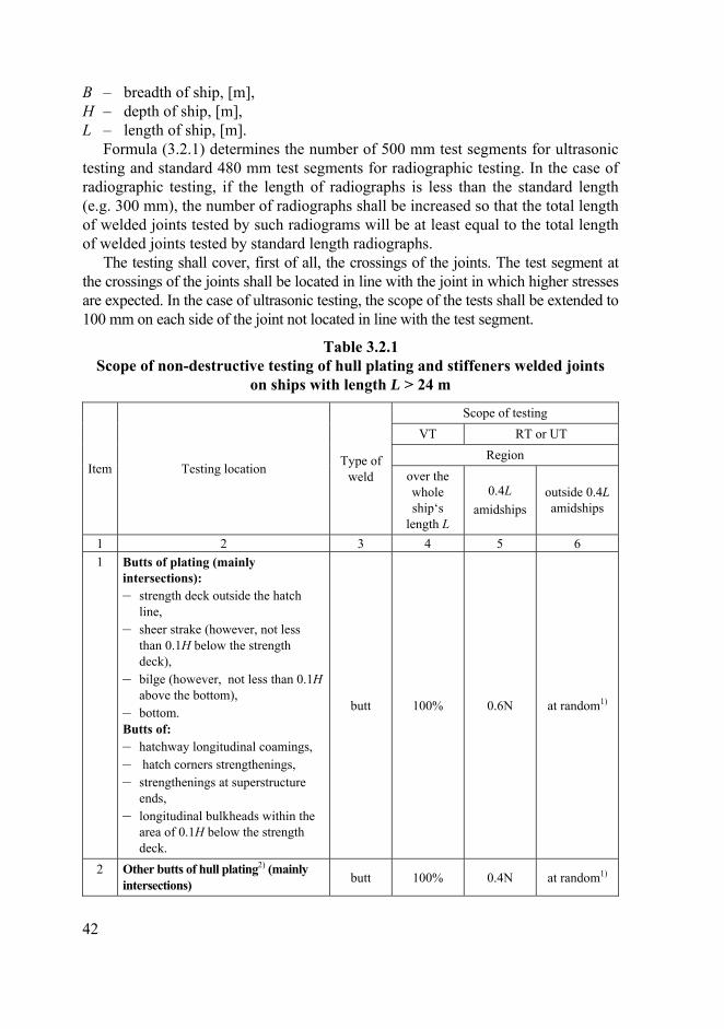
B – breadth of ship, [m], H – depth of ship, [m], L – length of ship, [m].
Formula (3.2.1) determines the number of 500 mm test segments for ultrasonic testing and standard 480 mm test segments for radiographic testing. In the case of radiographic testing, if the length of radiographs is less than the standard length (e.g. 300 mm), the number of radiographs shall be increased so that the total length of welded joints tested by such radiograms will be at least equal to the total length of welded joints tested by standard length radiographs.
The testing shall cover, first of all, the crossings of the joints. The test segment at the crossings of the joints shall be located in line with the joint in which higher stresses are expected. In the case of ultrasonic testing, the scope of the tests shall be extended to 100 mm on each side of the joint not located in line with the test segment.
Table 3.2.1 Scope of non-destructive testing of hull plating and stiffeners welded joints
on ships with length L > 24 m
Scope of testing VT RT or UT
Region Item Testing location Type of
weld over the whole ship‘s
length L
0.4L amidships
outside 0.4L amidships
1 2 3 4 5 6 1 Butts of plating (mainly
intersections): – strength deck outside the hatch
line, – sheer strake (however, not less
than 0.1H below the strength deck),
– bilge (however, not less than 0.1H above the bottom),
– bottom. Butts of: – hatchway longitudinal coamings, – hatch corners strengthenings, – strengthenings at superstructure
ends, – longitudinal bulkheads within the
area of 0.1H below the strength deck.
butt 100% 0.6N at random1)
2 Other butts of hull plating2) (mainly intersections) butt 100% 0.4N at random1)
42

1 2 3 4 5 6 3 Butts of longitudinal stiffeners
(longitudinal section): – strength deck outside hatch line, – sheer strake (however, not less than
0.1H below the strength deck), – bilge (however, not less than 0.1H
above the bottom), – bottom, – longitudinal bulkheads within the
area of 0.1H below the strength deck
butt 100%
1 test segment per each 5 butts (mainly
assembly butts)
at random1)
4 Other butts of longitudinal stiffeners
butt 100%
1 test segment per each 10 butts (mainly
assembly butts)
at random1)
5 Butts of transverse stiffeners (transverse section): butt 100%
1 test segment per each 10 butts
at random1)
6 Connection of stringer plate with sheer strake
angle joint with the butt
weld
100%
4 test segments subjected
to inspection
on the length of one steel sheet3)
at random 1), 3)
1) The number of test segments shall not exceed 35% of all test segments for the appropriate structural groups specified for the region 0.4L amidships.
2) In the case of ice strengthenings, ice belt butts shall be mainly tested. 3) Ultrasonic testing is recommended.
3.2.2
3.2.3
The scope of non-destructive testing of testing of the shell plating and stiffeners welded joints on ships with length L ≤ 24 m or the hull of inland waterway vessels shall be specified in Non-destructive Testing Plan for Welded Joints. The testing locations indicated in Table 3.2.1 shall be mainly tested. The scope of the testing, i.e. the number of test segments and their location are subject to a separate consideration of PRS.
In addition to hull structure elements specified in Table 3.2.1 or the requirements of paragraph 3.2.2, welded joints connecting the elements of equipment and hull structure elements, indicated in Table 3.2.3, shall be subjected
43

to non-destructive testing regardless of the ship’s length. Location of these tests shall be agreed with PRS’ Surveyor.
Table 3.2.3 Scope of non-destructive testing of welded joints
connecting the elements of equipment and hull structure elements
Scope of testing expressed as percentage Item Testing location
VT PT/MT/RT/UT1) 1 Hull and stern tube connection 100 100 2 Connection of hull and elements of rudder blade
suspension arrangement 100 100
3 Hull and shaft bracket connection 100 100 4 Connection of hull and thrust rudder tunnel 100 50 5 Connection of hull and main engines foundations 100 20 6 Connection of hull and auxiliary engines foundations 100 20 7 Connection of hull and lifting gear foundations 100 20 8 Connection of hull and masts foundations 100 20 9 Connection of hull and machinery and arrangements
foundations 100 20
1) Testing method is selected depending on the weld type of the tested weld joint.
3.2.4
3.2.5
On container ships, ultrasonic testing is to be carried out on all block-to-block butt joints of all upper flange longitudinal structural members in the cargo hold region. Upper flange longitudinal structural members include the topmost strakes of the inner hull/bulkhead, the sheer strake, main deck, coaming plate, coaming top plate and all attached longitudinal stiffeners defined in Fig. 3.2.4.
The scope of non-destructive testing of welded joints of the hull of a ship subjected to alteration or repair shall be each time agreed with PRS. The scope of the tests depends on the extent of the alteration or repair.
44

deck longitudinal
inner bulk longitudinal bulkhead longitudinal
side longitudinal
Fig. 3.2.4 Upper flange longitudinal structiral members
3.3 Scope of Non-destructive Testing of Welded Joints in Boilers, Pressure Vessels and Heat Exchangers
3.3.1 Welded joints in boilers, pressure vessels and heat exchangers under construction or repair shall be subjected to non-destructive testing within the scope specified in Table 3.3.1.
Table 3.3.1 Scope of non-destructive testing of welded joints in boilers, pressure vessels and heat exchangers
Scope of testing, expressed as percentage, of the total length of welded joints Structure class1) Joint type
VT RT or UT I 100 II 502) III
Longitudinal welds
as agreed with PRS I 502) II 252) III
Circumferential welds
100
as agreed with PRS
1) The division into classes is defined in the Rules for the Classification and Construction of Sea-going Ships, Part VII – Machinery, Boilers and Pressure Vessels.
2) Testing shall cover all crossings of welds.
45
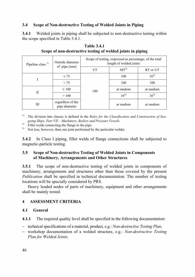
3.4 Scope of Non-destructive Testing of Welded Joints in Piping
3.4.1 Welded joints in piping shall be subjected to non-destructive testing within the scope specified in Table 3.4.1.
Table 3.4.1 Scope of non-destructive testing of welded joints in piping
Scope of testing, expressed as percentage, of the total length of welded joints Pipeline class 1) Outside diameter
of pipe [mm] VT MT2) RT or UT
≤ 75 100 103) I
> 75 100 100
≤ 100 at random at random II
> 100 103) 103)
III regardless of the
pipe diameter
100
at random at random
1) The division into classes is defined in the Rules for the Classification and Construction of Sea-going Ships, Part VII – Machinery, Boilers and Pressure Vessels.
2) Fillet welds connecting the flange to the pipe. 3) Not less, however, than one joint performed by the particular welder.
3.4.2
3.5.1
4.1.1
In Class I piping, fillet welds of flange connections shall be subjected to magnetic-particle testing.
3.5 Scope of Non-destructive Testing of Welded Joints in Components of Machinery, Arrangements and Other Structures
The scope of non-destructive testing of welded joints in components of machinery, arrangements and structures other than those covered by the present Publication shall be specified in technical documentation. The number of testing locations will be specially considered by PRS.
Heavy loaded nodes of parts of machinery, equipment and other arrangements shall be mainly tested.
4 ASSESSMENT CRITERIA
4.1 General
The required quality level shall be specified in the following documentation:
− technical specifications of a material, product, e.g.: Non-destructive Testing Plan, − workshop documentation of a welded structure, e.g.: Non-destructive Testing
Plan for Welded Joints.
46
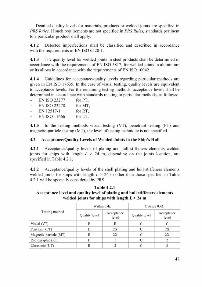
Detailed quality levels for materials, products or welded joints are specified in PRS Rules. If such requirements are not specified in PRS Rules, standards pertinent to a particular product shall apply.
4.1.2
4.1.3
4.1.4
4.1.5
4.2.1
4.2.2
Detected imperfections shall be classified and described in accordance with the requirements of EN ISO 6520-1.
The quality level for welded joints in steel products shall be determined in accordance with the requirements of EN ISO 5817, for welded joints in aluminium or its alloys in accordance with the requirements of EN ISO 10042.
Guidelines for acceptance/quality levels regarding particular methods are given in EN ISO 17635. In the case of visual testing, quality levels are equivalent to acceptance levels. For the remaining testing methods, acceptance levels shall be determined in accordance with standards relating to particular methods, as follows: − EN ISO 23277 for PT, − EN ISO 23278 for MT, − EN 12517-1 for RT, − EN ISO 11666 for UT.
In the testing methods visual testing (VT), penetrant testing (PT) and magnetic-particle testing (MT), the level of testing technique is not specified.
4.2 Acceptance/Quality Levels of Welded Joints in the Ship’s Hull
Acceptance/quality levels of plating and hull stiffeners elements welded joints for ships with length L > 24 m, depending on the joints location, are specified in Table 4.2.1.
Acceptance/quality levels of the shell plating and hull stiffeners elements welded joints for ships with length L > 24 m other than those specified in Table 4.2.1 will be specially considered by PRS.
Table 4.2.1 Acceptance level and quality level of plating and hull stiffeners elements
welded joints for ships with length L > 24 m
Within 0.4L Outside 0.4L Testing method
Quality level Acceptance level Quality level Acceptance
level
Visual (VT) B B C C Penetrant (PT) B 2X C 2X Magnetic-particle (MT) B 2X C 2X Radiographic (RT) B 1 C 2 Ultrasonic (UT) B 2 C 3
47

4.2.3 Acceptance/quality levels of the shell plating and hull stiffeners elements welded joints for ships with length L ≤ 24 m and inland waterway vessels are specified in Table 4.2.3.
Table 4.2.3 Acceptance/quality levels of plating and hull stiffeners elements welded joints
for ships with length L ≤ 24 m and inland waterways vessels
Testing method Quality level Acceptance level
Visual (VT) C C
Penetrant (PT) C 2X
Magnetic-particle (MT) C 2X
Radiographic (RT) C 2
Ultrasonic (UT) C 3
4.2.4
4.2.5
4.2.6
Acceptance/quality levels of the shell plating and hull stiffeners elements welded joints for ships with length L ≤ 24 m lower than those specified in Table 4.2.3 will be specially considered by PRS.
Acceptance/quality levels of welded joints connecting the elements of equipment and hull structure elements, are given in Table 4.2.5.
Acceptance/quality levels of welded joints connecting the elements of equipment and hull structure elements lower than those indicated in Table 4.2.5 will be specially considered by PRS.
Table 4.2.5 Acceptance/quality levels of welded joints connecting the elements
of equipment and hull structure elements
Acceptance level Item Testing location
VT PT MT RT UT Quality level
1 2 3 4 5 6 7 8 1 Hull plating and stern tube
connection B 1 1 1 2 B
2 Connection of hull plating and elements of rudder blade suspension arrangement
B 1 1 1 2 B
3 Hull and shaft bracket connection B 1 1 1 2 B 4 Connection of hull and thrust
rudder tunnel B 1 1 1 2 B
5 Connection of hull and main engines foundations B 1 1 1 2 B
48

1 2 3 4 5 6 7 8 6 Connection of hull and auxiliary
engines foundations C 2X 2X 2 3 C
7 Connection of hull and lifting gear foundations B 1 1 1 2 B
8 Connection of hull and masts foundations C 2X 2X 2 3 C
9 Connection of hull and machinery and arrangements foundations C 2X 2X 2 3 C
4.3 Acceptance/Quality Levels of Welded Joints in Boilers, Pressure Vessels and Heat Exchangers
4.3.1 Acceptance/quality levels of welded joints in boilers, pressure vessels and heat exchangers, depending on their class, are specified in Table 4.3.1.
Table 4.3.1 Acceptance/quality levels of welded joints in boilers, pressure vessels
and heat exchangers, depending on their class1)
Class I Class II Class III Testing method Quality
level Acceptance
level Quality
level Acceptance
level Quality
level Acceptance
level Visual (VT) B B C C C C Penetrant (PT) B 1 C 2X C 2X Magnetic-particle (MT) B 1 C 2X C 2X Radiographic (RT) B 1 C 2 C 2 Ultrasonic (UT) B 2 C 3 C 3
1) The division into classes is defined in the Rules for the Classification and Construction of Sea-going Ships, Part VII – Machinery, Boilers and Pressure Vessels.
4.3.2
4.4.1
Acceptance/quality levels of welded joints in boilers, pressure vessels and heat exchangers lower than those given in Table 4.3.1 will be specially considered by PRS. Welded joints of quality level D are not permitted for Class I boilers, pressure vessels and heat exchangers.
4.4 Acceptance/Quality Levels of Welded Joints in Piping
Acceptance/quality levels of welded joints in piping, depending on the piping class, are specified in Table 4.4.1.
49

Table 4.4.1 Acceptance/quality levels of welded joints in piping, depending
on the piping class1)
Class I Class II Class III Testing method Quality
level Acceptance
level Quality
level Acceptance
level Quality
level Acceptance
level Visual (VT) B B C C C C Penetrant (PT) B 1 C 2X C 2X Magnetic-particle (MT) B 1 C 2X C 2X Radiographic (RT) B 1 C 2 C 2 Ultrasonic (UT) B 2 C 3 C 3
1) The division into classes is defined in the Rules for the Classification and Construction of Sea-going Ships, Part VII – Machinery, Boilers and Pressure Vessels.
4.4.2
4.5.1
Acceptance/quality levels of welded joints in piping lower than those specified in Table 4.4.1 will be specially considered by PRS. Welded joints of quality level D are not permitted for Class I piping.
4.5 Acceptance/Quality Levels of Welded Joints in Elements of Machinery, Arrangements and Other Structures
Acceptance/quality levels of welded joints in elements of machinery, arrangements and other structures than those given in the present Publication shall be specified in technical documentation and will be specially considered by PRS.
50