Profibus MKIV CPrev01
28
User Guide for Profibus Protocol on Elektronikon ComBox-P Name Mark IV : User Guide Serc. Class 1102 K/1 Detail User Guide Profibus Protocol on Elektronikon ComBox-P PC Owner Edition Modified from Print date AII 00 Family Written by Compare Replaces Designation CTE-PVT Design checked. Production checked. Approved Date 9820 3582 03
-
Upload
dilip-kumar -
Category
Documents
-
view
234 -
download
0
Transcript of Profibus MKIV CPrev01
7/23/2019 Profibus MKIV CPrev01
http://slidepdf.com/reader/full/profibus-mkiv-cprev01 1/28
User Guide for
Profibus Protocol on Elektronikon ComBox-P
Name Mark IV : User Guide Serc. Class
1102 K/1Detail User Guide Profibus Protocol on Elektronikon ComBox-P
PC Owner
Edition Modified from Print date AII00Family Written by Compare Replaces Designation
CTE-PVT
Design checked. Production checked. Approved Date9820 3582 03

7/23/2019 Profibus MKIV CPrev01
http://slidepdf.com/reader/full/profibus-mkiv-cprev01 2/28
Profibus Protocol for ComBox-P
File :9820 3582 03 User Guide MKIV Profibus.doc Project : - Page 1
Document Information
Edition Date Description Author
0 Draft update CTE

7/23/2019 Profibus MKIV CPrev01
http://slidepdf.com/reader/full/profibus-mkiv-cprev01 3/28
Profibus Protocol for ComBox-P
File :9820 3582 03 User Guide MKIV Profibus.doc Project : - Page 2
Table of Contents
1 Preface ..............................................................................................................................................................................4
2 The Physical set-up...........................................................................................................................................................4
2.1 Profibus & the Network............................................................................................................................................4
2.2 The Module (Combox-P)..........................................................................................................................................52.3 LED’s........................................................................................................................................................................6
2.4 Connector lay-out .....................................................................................................................................................7
2.4.1 Power Supply....................................................................................................................................................7
2.4.2 LAN connector .................................................................................................................................................72.4.3 Profibus connection ..........................................................................................................................................7
Pin Assignment Profibbus.........................................................................................................................................73 Basic Protocol...................................................................................................................................................................8
4 Profile definition...............................................................................................................................................................8
4.1 Master – Slave concept .............................................................................................................................................8
4.2 Buffer structure.........................................................................................................................................................8
4.3 Header.......................................................................................................................................................................8
4.3.1 Master to Slave .................................................................................................................................................8
4.3.2 Slave to Master .................................................................................................................................................9
4.4 Data Record ............................................................................................................................................................10
4.4.1 Node Address..................................................................................................................................................10
4.4.2 Profibus Parameter ID for Data Reading ........................................................................................................11
4.4.2.1 Compressor connection...............................................................................................................................114.4.2.2 Detailed General Compressor Condition ....................................................................................................12
4.4.3 Inputs & Outputs.............................................................................................................................................13
4.4.3.1 Analogue Inputs – Sensors & Calculated....................................................................................................13
4.4.3.2 ParameterID................................................................................................................................................13
4.4.3.2.1 Sensor Inputs.........................................................................................................................................13
4.4.3.2.2 Calculated (virtual) Inputs ...................................................................................................................13
4.4.3.3 “Status” register Interpretation....................................................................................................................14
4.4.3.4 “Value” register Interpretation....................................................................................................................14
1.1.1.1.1 Pressure Input .......................................................................................................................................14
1.1.1.1.2 Temperature Input.................................................................................................................................14
4.4.3.4.1 Vibration Input......................................................................................................................................144.4.3.4.2 Level Input............................................................................................................................................14
4.4.3.4.3 Conductivity Input ................................................................................................................................144.4.3.4.4 SPM Input.............................................................................................................................................14
4.4.3.4.5 Current Input.........................................................................................................................................14
4.4.3.4.6 Speed Input ...........................................................................................................................................14
4.4.3.5 Digital (Voltage free contacts) Inputs.........................................................................................................154.4.3.6 “Status” register Interpretation....................................................................................................................15
4.4.3.7 “Value” register Interpretation....................................................................................................................15
4.4.4 Counters..........................................................................................................................................................16
4.4.4.1 Compressor Counters..................................................................................................................................16
4.4.4.2 Multi Compressor Controller Counters.......................................................................................................17
4.4.5 Special.............................................................................................................................................................184.4.5.1 VSD motor data ..........................................................................................................................................18
4.5 Profibus parameters for change...............................................................................................................................19
4.5.1 Load/Unload Pressure Band change ...............................................................................................................194.5.2 VSD Setpoint change......................................................................................................................................19
4.5.3 MCC Pressure Band change ...........................................................................................................................20
7/23/2019 Profibus MKIV CPrev01
http://slidepdf.com/reader/full/profibus-mkiv-cprev01 4/28
Profibus Protocol for ComBox-P
File :9820 3582 03 User Guide MKIV Profibus.doc Project : - Page 3
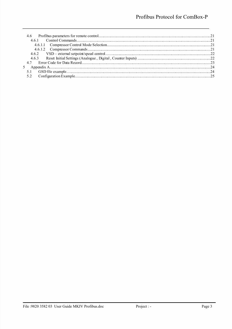
4.6 Profibus parameters for remote control...................................................................................................................21
4.6.1 Control Commands.........................................................................................................................................21
4.6.1.1 Compressor Control Mode Selection..........................................................................................................21
4.6.1.2 Compressor Commands..............................................................................................................................214.6.2 VSD – external setpoint/speed control............................................................................................................22
4.6.3 Reset Initial Settings (Analogue , Digital , Counter Inputs) ...........................................................................224.7 Error Code for Data Record....................................................................................................................................23
5 Appendix A.....................................................................................................................................................................24
5.1 GSD file example....................................................................................................................................................24
5.2 Configuration Example...........................................................................................................................................25
7/23/2019 Profibus MKIV CPrev01
http://slidepdf.com/reader/full/profibus-mkiv-cprev01 5/28
Profibus Protocol for ComBox-P
File :9820 3582 03 User Guide MKIV Profibus.doc Project : - Page 4
1 Preface
This document describes Elektronikon MkIV Profibus Profile that is used by the ComBox-P communication
processor.
2 The Physical set-up
2.1 Profibus & the Network
In the Elektronikon MkIV system all compressors in an installation can be connected by a data and/or control network. This
is done according the Compressor Network Cabling Instruction (9820 3585 00). This instruction explains what connectors
and cables should be used to interconnect the different compressors/controllers in the network. Basically this is a CAN-
based local network.
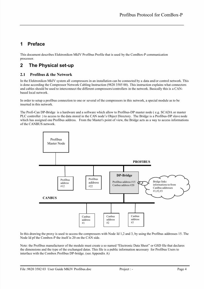
In order to setup a profibus connection to one or several of the compressors in this network, a special module as to beinserted in this network.
The Profi-Can DP-Bridge is a hardware and a software which allow to Profibus-DP master node ( e.g. SCADA or master
PLC controller ) to access to the data stored in the CAN node’s Object Directory. The Bridge is a Profibus-DP slave nodewhich has assigned one Profibus address. From the Master's point of view, the Bridge acts as a way to access informations
of the CANBUS network.
In this drawing the proxy is used to access the compressors with Node Id 1,2 and 3, by using the Profibus addresses 15. The
Node Id pf the Combox-P the itself is 20 on the CAN side.
Note: the Profibus manufacturer of the module must create a so named “Electronic Data Sheet” or GSD file that declares
the dimensions and the type of the exchanged datas. This file is a public information necessary for Profibus Users to
interface with the Combox Profibus DP-bridge. (see Appendix A)
Profibus
Master Node
Profibusaddress
#12
Profibus
address#22
DP-Bridge
Profibus address #15
Canbus address #20
Canbus
address
#1
Canbus
address
#2
Canbus
address
#3
PROFIBUS
CANBUS
Bridge linksinformations to/from
CanBus addresses
#1,#2,#3
7/23/2019 Profibus MKIV CPrev01
http://slidepdf.com/reader/full/profibus-mkiv-cprev01 6/28
Profibus Protocol for ComBox-P
File :9820 3582 03 User Guide MKIV Profibus.doc Project : - Page 5
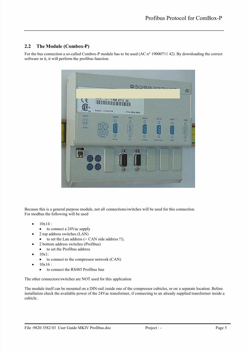
2.2 The Module (Combox-P)
For the bus connection a so-called Combox-P module has to be used (AC n° 19000711 42). By downloading the correct
software in it, it will perform the profibus function.
Because this is a general purpose module, not all connections/switches will be used for this connection.
For modbus the following will be used
10x14 :
to connect a 24Vac supply
2 top address switches (LAN)
to set the Lan address (= CAN side address !!),
2 bottom address switches (Profibus)
to set the Profibus address
10x1:
to connect to the compressor network (CAN)
10x16 :
to connect the RS485 Profibus line
The other connectors/switches are NOT used for this application
The module itself can be mounted on a DIN-rail inside one of the compressor cubicles, or on a separate location. Before
installation check the available power of the 24Vac transformer, if connecting to an already supplied transformer inside a
cubicle..

7/23/2019 Profibus MKIV CPrev01
http://slidepdf.com/reader/full/profibus-mkiv-cprev01 7/28
Profibus Protocol for ComBox-P
File :9820 3582 03 User Guide MKIV Profibus.doc Project : - Page 6
2.3 LED’s
The module also has a number of LED’s on type. They are used as follows :
System LED (the most right LED)
Blinking : no program loaded or not running
Lit continuously : program running OK
Application LED’s from left to right
1. not used
2. not used
3. CAN receive (Combox receives CAN message)
4. CAN transmit (Combox transmits CAN message)
5. Profibus receive (Combox receives Profibus message)
6. Profibus transmit (Combox transmits Profibus message)
7. not used
8. not used
9. not used
10. not used
11. not used

7/23/2019 Profibus MKIV CPrev01
http://slidepdf.com/reader/full/profibus-mkiv-cprev01 8/28
Profibus Protocol for ComBox-P
File :9820 3582 03 User Guide MKIV Profibus.doc Project : - Page 7
2.4 Connector lay-out
2.4.1 Power Supply
This is a two pole Wago (type …) connector. Power supply is 24Vac, 10VA2.4.2 LAN connector
Connect here the cable of the compressor network, according instruction : Compressor Network Cabling Instruction
(9820 3585 00).
2.4.3 Profibus connection
The module supports the RS485A variant of Profibus, with the following pin-layout and termination requirements as
specified
Pin Assignment Profibbus
Sub-D 9 pole female
Pin Function1 GND
2 Reserved
3 B-signal
4 Resereved
5 GND*
6 +5V*
7 Reserved
8 A-signal
9 Reserved* galvanic isolated
1
6
7/23/2019 Profibus MKIV CPrev01
http://slidepdf.com/reader/full/profibus-mkiv-cprev01 9/28
Profibus Protocol for ComBox-P
File :9820 3582 03 User Guide MKIV Profibus.doc Project : - Page 8
3 Basic Protocol
The profile is based on the standard Profibus-DP protocol, with following basic specifications:
DP-Slave on Siemens SPC3 Asic
RS485
Baudrate: 9.600 Kbaud to 12.000 Mbaud
Autobaud: supported
Freeze Mode: Not supported
Sync Mode: Not supported
Slave Node Address Change: not supported
Diagnostics : not supported
4 Profile definition
4.1 Master – Slave concept
The profile is based upon the master-slave principle. This means all communication is initiated by the master and a reply is
generated by the slave (ComBox-P).
All buffers should be full length consistent.
4.2 Buffer structure
The Profile can be used for buffers with different length: 8,16,32 and 64 bytes. The buffer length has to be defined and
initialised during downloading of the software inside the ComBox-P.
The DP buffer is split into 2 parts :
header : 1 byte data section : n * data record (= 7 bytes) (Is programmeble in the combox (1,2,4,8))
n is defined by the total buffer length as follows
Buffer length Number of data record (n) Total used buffer length
8 1 8
16 2 15
32 4 29
64 8 57
Attention : not all functions allow more then 1 data record to be transferred. Basically read operations can be handled for several data records in 1 cycle, while write operations are only valid for a single data record at a time.
4.3 Header
The header is a 1 byte value that is bit encoded. The interpretation is different for Master->slave and Slave->Master
communication.
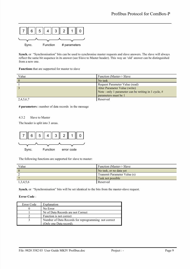
4.3.1 Master to Slave
The header is split into 3 areas.
7/23/2019 Profibus MKIV CPrev01
http://slidepdf.com/reader/full/profibus-mkiv-cprev01 10/28
Profibus Protocol for ComBox-P
File :9820 3582 03 User Guide MKIV Profibus.doc Project : - Page 9
Synch. or “Synchronisation” bits can be used to synchronise master requests and slave answers. The slave will always
reflect the same bit sequence in its answer (see Slave to Master header). This way an ‘old’ answer can be distinguished
from a new one.
Functions that are supported for master to slave
Value Function (Master-> Slave
0 No task
1 Request Parameter Value (read)
3 Alter Parameter Value (write)
Note : only 1 parameter can be writing in 1 cycle, #
parameters must be 1
2,4,5,6,7 Reserved
# parameters : number of data records in the message
4.3.2 Slave to Master
The header is split into 3 areas.
The following functions are supported for slave to master:
Value Function (Master-> Slave
0 No task, or no data yet
2 Transmit Parameter Value (s)
7 Task not possible
1,3,4,5,6 Reserved
Synch. or “Synchronisation” bits will be set identical to the bits from the master-slave request.
Error Code :
Error Code Explanation
0 No Error
1 Nr of Data Records are not Correct
2 Function is not correct
3 Number of Data Records for reprogramming not correct
(Only one Data record).
01234567
Function # parametersSync.
01234567
Function error codeSync.

7/23/2019 Profibus MKIV CPrev01
http://slidepdf.com/reader/full/profibus-mkiv-cprev01 11/28
Profibus Protocol for ComBox-P
File :9820 3582 03 User Guide MKIV Profibus.doc Project : - Page 10
4.4 Data Record
Each data record is 7 bytes long and contains the following info:
Node Address : 1 bytes, CAN address of slave to connect to
Parameter ID : 2 bytes, ID of the parameter to read/write
Data : 4 bytes, containing actual data
4.4.1 Node Address
This is the Elektronikon MkIV CAN address : 1 to 30 (31 only used for default factory setting, should not be used in
network).
Additional error info : bit 7 (highest bit) will be set to 1 in a Slave to Master Data Record, if this data record contains an
error.
7/23/2019 Profibus MKIV CPrev01
http://slidepdf.com/reader/full/profibus-mkiv-cprev01 12/28
Profibus Protocol for ComBox-P
File :9820 3582 03 User Guide MKIV Profibus.doc Project : - Page 11
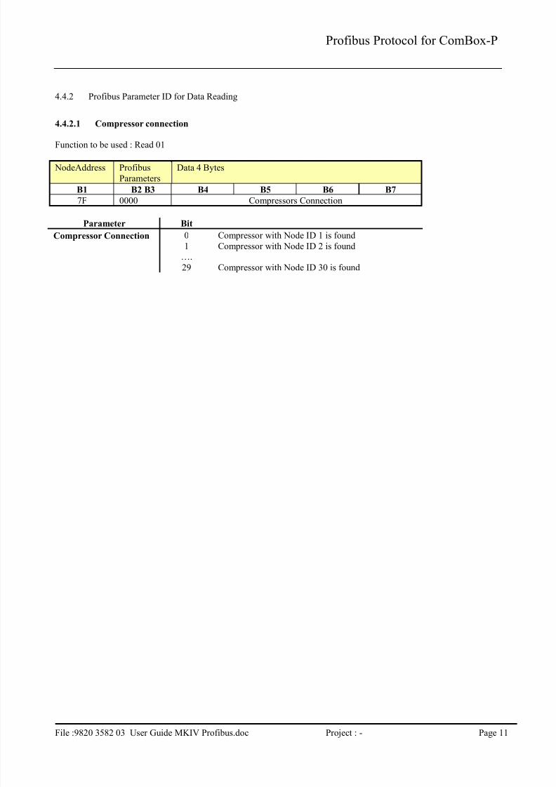
4.4.2 Profibus Parameter ID for Data Reading
4.4.2.1 Compressor connection
Function to be used : Read 01
NodeAddress Profibus
Parameters
Data 4 Bytes
B1 B2 B3 B4 B5 B6 B7
7F 0000 Compressors Connection
Parameter Bit
Compressor Connection 0 Compressor with Node ID 1 is found
1 Compressor with Node ID 2 is found….
29 Compressor with Node ID 30 is found
7/23/2019 Profibus MKIV CPrev01
http://slidepdf.com/reader/full/profibus-mkiv-cprev01 13/28
Profibus Protocol for ComBox-P
File :9820 3582 03 User Guide MKIV Profibus.doc Project : - Page 12
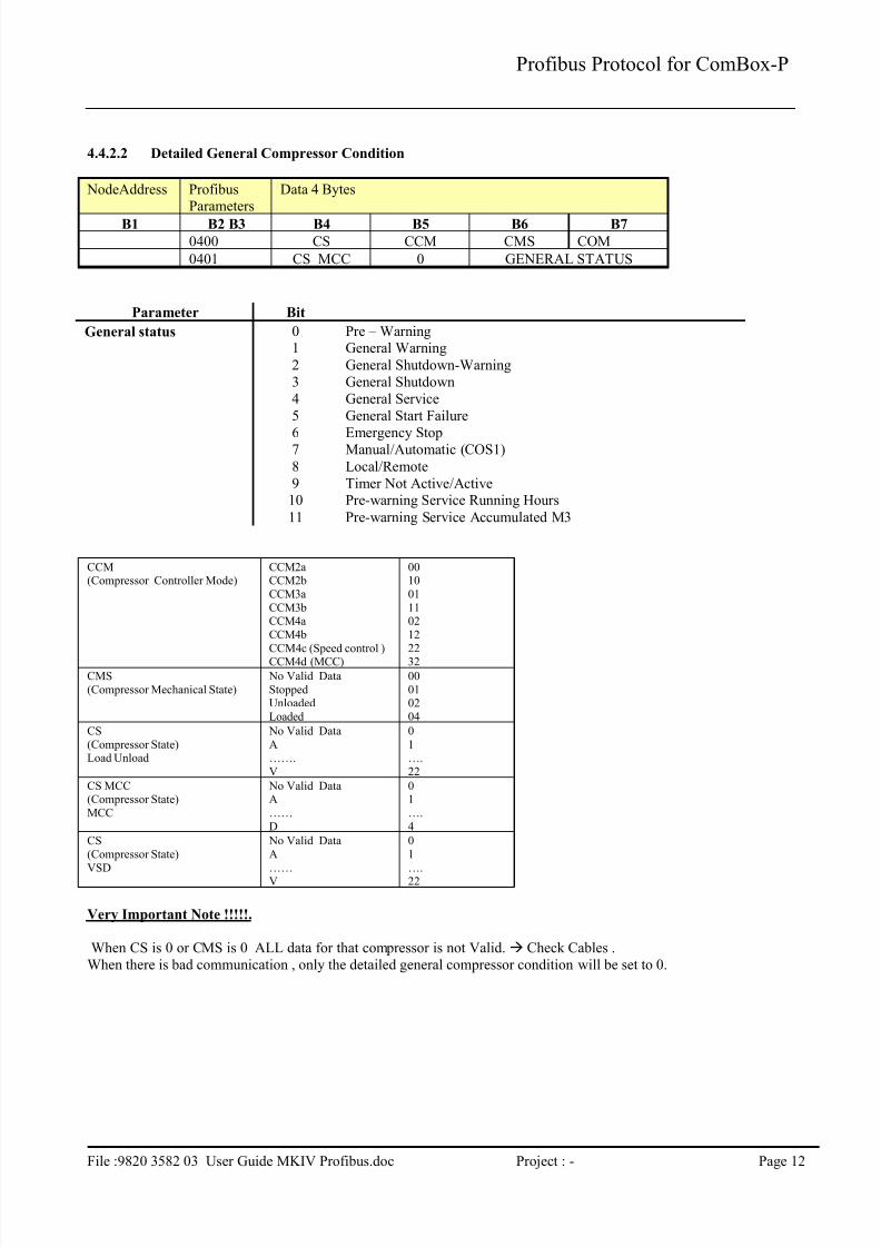
4.4.2.2 Detailed General Compressor Condition
NodeAddress ProfibusParameters
Data 4 Bytes
B1 B2 B3 B4 B5 B6 B7
0400 CS CCM CMS COM
0401 CS_MCC 0 GENERAL STATUS
Parameter Bit
General status 0 Pre – Warning1 General Warning
2 General Shutdown-Warning
3 General Shutdown
4 General Service
5 General Start Failure
6 Emergency Stop7 Manual/Automatic (COS1)
8 Local/Remote
9 Timer Not Active/Active10 Pre-warning Service Running Hours
11 Pre-warning Service Accumulated M3
CCM(Compressor Controller Mode)
CCM2aCCM2b
CCM3a
CCM3bCCM4a
CCM4b
CCM4c (Speed control )CCM4d (MCC)
0010
01
1102
12
2232
CMS
(Compressor Mechanical State)
No Valid Data
StoppedUnloaded
Loaded
00
0102
04
CS
(Compressor State)Load Unload
No Valid Data
A…….
V
0
1….
22
CS MCC(Compressor State)
MCC
No Valid DataA
……
D
01
….
4
CS
(Compressor State)
VSD
No Valid Data
A
……V
0
1
….22
Very Important Note !!!!!.
When CS is 0 or CMS is 0 ALL data for that compressor is not Valid. Check Cables .
When there is bad communication , only the detailed general compressor condition will be set to 0.
7/23/2019 Profibus MKIV CPrev01
http://slidepdf.com/reader/full/profibus-mkiv-cprev01 14/28
Profibus Protocol for ComBox-P
File :9820 3582 03 User Guide MKIV Profibus.doc Project : - Page 13
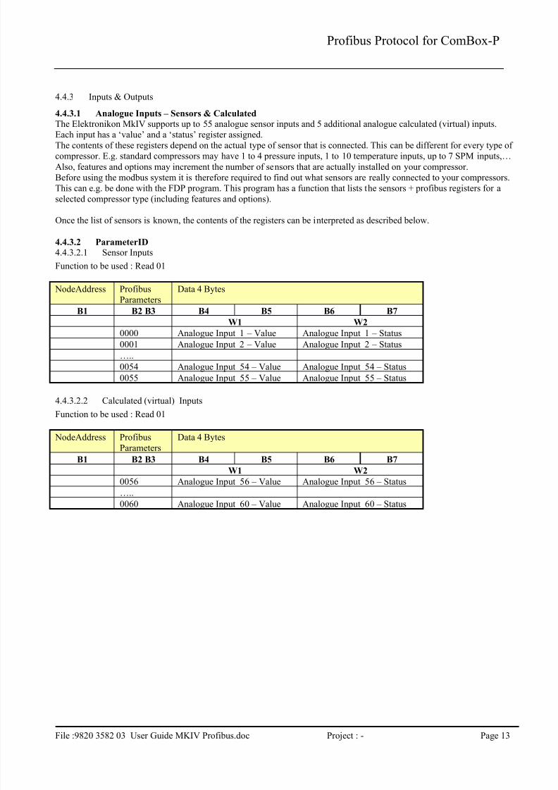
4.4.3 Inputs & Outputs
4.4.3.1 Analogue Inputs – Sensors & Calculated
The Elektronikon MkIV supports up to 55 analogue sensor inputs and 5 additional analogue calculated (virtual) inputs.
Each input has a ‘value’ and a ‘status’ register assigned.The contents of these registers depend on the actual type of sensor that is connected. This can be different for every type of
compressor. E.g. standard compressors may have 1 to 4 pressure inputs, 1 to 10 temperature inputs, up to 7 SPM inputs,…
Also, features and options may increment the number of sensors that are actually installed on your compressor.
Before using the modbus system it is therefore required to find out what sensors are really connected to your compressors.
This can e.g. be done with the FDP program. This program has a function that lists the sensors + profibus registers for a
selected compressor type (including features and options).
Once the list of sensors is known, the contents of the registers can be interpreted as described below.
4.4.3.2 ParameterID
4.4.3.2.1 Sensor Inputs
Function to be used : Read 01
NodeAddress Profibus
Parameters
Data 4 Bytes
B1 B2 B3 B4 B5 B6 B7
W1 W2
0000 Analogue Input 1 – Value Analogue Input 1 – Status
0001 Analogue Input 2 – Value Analogue Input 2 – Status
…..
0054 Analogue Input 54 – Value Analogue Input 54 – Status
0055 Analogue Input 55 – Value Analogue Input 55 – Status
4.4.3.2.2 Calculated (virtual) Inputs
Function to be used : Read 01
NodeAddress Profibus
Parameters
Data 4 Bytes
B1 B2 B3 B4 B5 B6 B7
W1 W2
0056 Analogue Input 56 – Value Analogue Input 56 – Status
…..
0060 Analogue Input 60 – Value Analogue Input 60 – Status

7/23/2019 Profibus MKIV CPrev01
http://slidepdf.com/reader/full/profibus-mkiv-cprev01 15/28
Profibus Protocol for ComBox-P
File :9820 3582 03 User Guide MKIV Profibus.doc Project : - Page 14
4.4.3.3 “Status” register Interpretation
Byte 6 (B6) = 00
Byte 7 (B7) = Input Status
The Input Status must be interpreted as Binary data (bit coded).Each part ( bit ) of the data ( byte ) is indicating a specific item that applies on the Input function. In the following table, an
overview is given of all bits together with the corresponding meaning and interpretation.
Bit 7 Bit 6 Bit 5 Bit 4 Bit 3 Bit 2 Bit 1 Bit 0
Function
Description
Input
Set/Not Set
Sensor
Error
Permissive
Start
Service Shutdown Shutdown
Warning
Warning Pre-
Warning
Bit “1” Set Active Active Active Active Active Active Active
Bit “0” Not Set Not Active Not Active Not Active Not Active Not Active Not Active Not Active
4.4.3.4 “Value” register Interpretation
This depends on the type of inputs.
1.1.1.1.1 Pressure Input
The Pressure Input Value is a 2 byte integer, and contains the actual reading in mbar (0.001 bar)
For negative values, standard 2-complement notation is used.
Example: Value = 7040 decimal or 0x1B80 hexadecimal = 7.040 bar.
Value = -1000 decimal (2-complement) or 0xFC18 = -1.000 bar
For sensor error the value the value 32767 or 7FFF (hex) is returned.
On some high pressure compressors (with working pressures above 30 bar) a special Pressure Input can be defined that
returns data in cBar (0.01 bar) in stead of mBar.
1.1.1.1.2 Temperature Input
The Temperature Input Value is a 2 byte integer, and contains the actual reading in 0.1°CFor negative values, standard 2-complement notation is used.
Example: Value = 855 decimal or 0x0357 hexadecimal = 85.5 °C
Value = -250 decimal (2-complement) or 0xFF06 = -25.0 °C
For sensor error the value the value 32767 or 7FFF (hex) is returned.4.4.3.4.1 Vibration Input
tbd
4.4.3.4.2 Level Input
tbd4.4.3.4.3 Conductivity Input
tbd
4.4.3.4.4 SPM Input
The SPM Input Value is a 2 byte register that must be seen as 2 x 1 byte.
Byte 1 : carpet value (in dB)
Byte 2 : peak value (in dB)
Example: Value = 0x1120 = > carpet value = 0x11, peak value = 0x20
For sensor error the value the value 0xFFFF (hex) is returned.
SPM values cannot be negative
4.4.3.4.5 Current Input
tbd
4.4.3.4.6 Speed Input
tbd
7/23/2019 Profibus MKIV CPrev01
http://slidepdf.com/reader/full/profibus-mkiv-cprev01 16/28
Profibus Protocol for ComBox-P
File :9820 3582 03 User Guide MKIV Profibus.doc Project : - Page 15
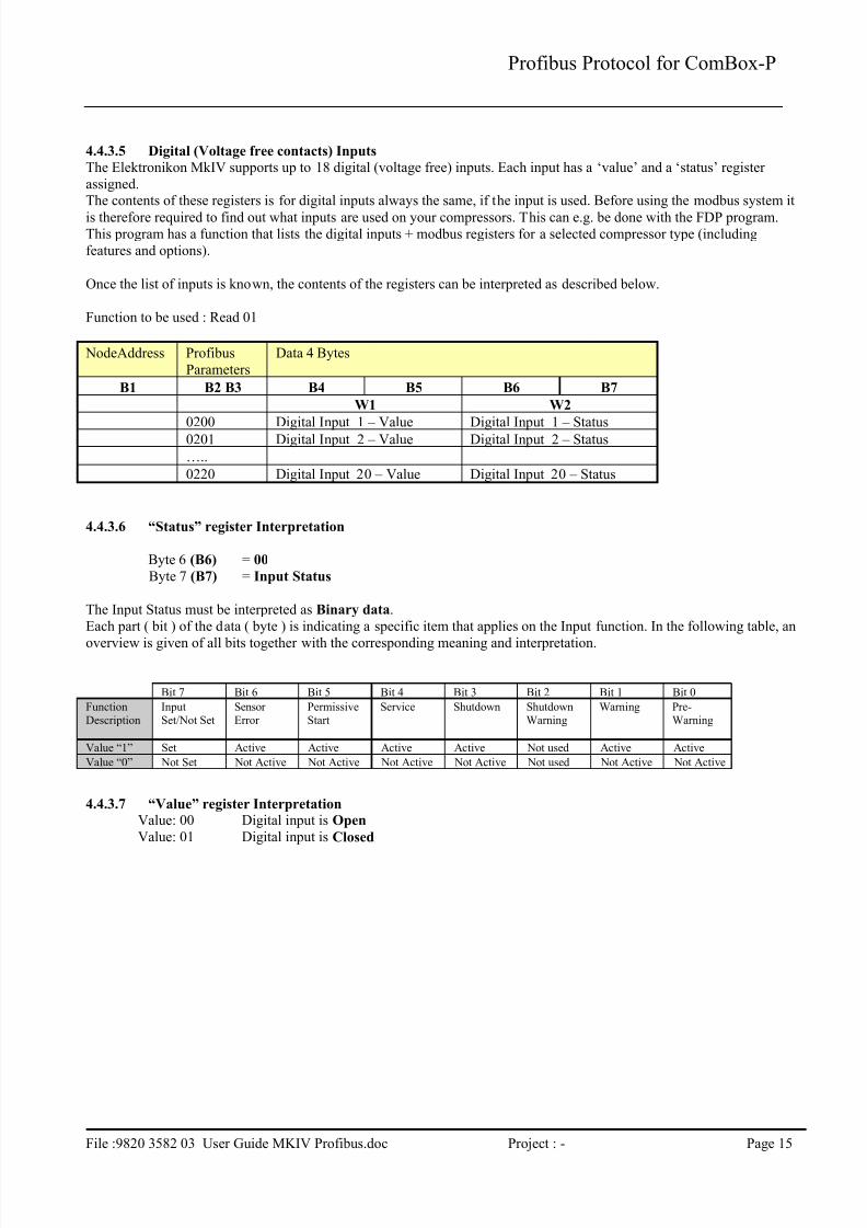
4.4.3.5 Digital (Voltage free contacts) Inputs
The Elektronikon MkIV supports up to 18 digital (voltage free) inputs. Each input has a ‘value’ and a ‘status’ register
assigned.The contents of these registers is for digital inputs always the same, if the input is used. Before using the modbus system it
is therefore required to find out what inputs are used on your compressors. This can e.g. be done with the FDP program.This program has a function that lists the digital inputs + modbus registers for a selected compressor type (including
features and options).
Once the list of inputs is known, the contents of the registers can be interpreted as described below.
Function to be used : Read 01
NodeAddress Profibus
Parameters
Data 4 Bytes
B1 B2 B3 B4 B5 B6 B7
W1 W2
0200 Digital Input 1 – Value Digital Input 1 – Status
0201 Digital Input 2 – Value Digital Input 2 – Status
…..
0220 Digital Input 20 – Value Digital Input 20 – Status
4.4.3.6 “Status” register Interpretation
Byte 6 (B6) = 00
Byte 7 (B7) = Input Status
The Input Status must be interpreted as Binary data.
Each part ( bit ) of the data ( byte ) is indicating a specific item that applies on the Input function. In the following table, an
overview is given of all bits together with the corresponding meaning and interpretation.
Bit 7 Bit 6 Bit 5 Bit 4 Bit 3 Bit 2 Bit 1 Bit 0
Function
Description
Input
Set/Not Set
Sensor
Error
Permissive
Start
Service Shutdown Shutdown
Warning
Warning Pre-
Warning
Value “1” Set Active Active Active Active Not used Active Active
Value “0” Not Set Not Active Not Active Not Active Not Active Not used Not Active Not Active
4.4.3.7 “Value” register Interpretation
Value: 00 Digital input is Open
Value: 01 Digital input is Closed

7/23/2019 Profibus MKIV CPrev01
http://slidepdf.com/reader/full/profibus-mkiv-cprev01 17/28
Profibus Protocol for ComBox-P
File :9820 3582 03 User Guide MKIV Profibus.doc Project : - Page 16
4.4.4 Counters
4.4.4.1 Compressor Counters
The Elektronikon MkIV supports up to 28 counters (32-bit counters). Each input as 2 x 16bit ‘value’ register assigned, to
allow a 32-bit value to be read. Not all types of compressors use all types of counters. The list in this chapter provides an overview of the used counters /
compressor type, and the units that are used
Function to be used : Read 01
NodeAddress
ProfibusParameters
Data 4 Bytes
B1 B2 B3 B4 B5 B6 B7
W1 W2 Units Load/Unload VSD
0300 Running Hours s X X
0301 Loaded Hours s X -/ X*
0302 Motor Starts Number X X
0303 Module Hours s X X0304 Accumulated Volume 1000 m³ - X
0305 Load cycle Number X -/ X*
0306 VSD 1-20% RPM % - X
0307 VSD 20-40% RPM % - X
0308 VSD 40-60% RPM % - X
0309 VSD 60-80% RPM % - X
0310 VSD 80-100% RPM % - X
yes, if VSD has unloading cycle (e.g. Z-VSD)
Interpretation of data in the registers
Example Running Hours
Running Hours B4 B5 B6 B7
00 2C 93 45
2921285 sec 811 hrs
7/23/2019 Profibus MKIV CPrev01
http://slidepdf.com/reader/full/profibus-mkiv-cprev01 18/28
Profibus Protocol for ComBox-P
File :9820 3582 03 User Guide MKIV Profibus.doc Project : - Page 17
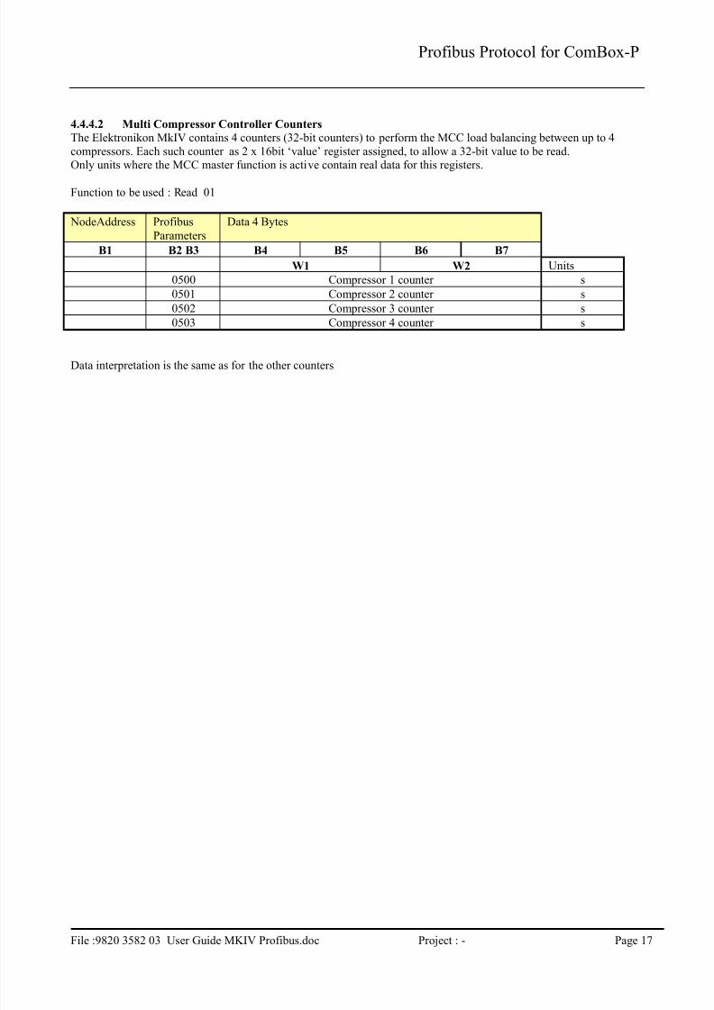
4.4.4.2 Multi Compressor Controller Counters
The Elektronikon MkIV contains 4 counters (32-bit counters) to perform the MCC load balancing between up to 4
compressors. Each such counter as 2 x 16bit ‘value’ register assigned, to allow a 32-bit value to be read.Only units where the MCC master function is active contain real data for this registers.
Function to be used : Read 01
NodeAddress Profibus
Parameters
Data 4 Bytes
B1 B2 B3 B4 B5 B6 B7
W1 W2 Units
0500 Compressor 1 counter s
0501 Compressor 2 counter s
0502 Compressor 3 counter s
0503 Compressor 4 counter s
Data interpretation is the same as for the other counters
7/23/2019 Profibus MKIV CPrev01
http://slidepdf.com/reader/full/profibus-mkiv-cprev01 19/28
Profibus Protocol for ComBox-P
File :9820 3582 03 User Guide MKIV Profibus.doc Project : - Page 18
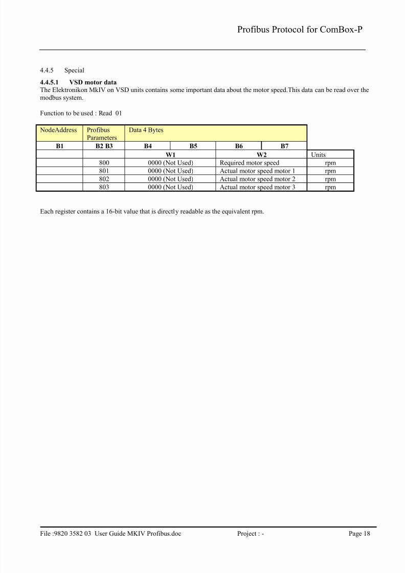
4.4.5 Special
4.4.5.1 VSD motor data
The Elektronikon MkIV on VSD units contains some important data about the motor speed.This data can be read over the
modbus system.
Function to be used : Read 01
NodeAddress Profibus
Parameters
Data 4 Bytes
B1 B2 B3 B4 B5 B6 B7
W1 W2 Units
800 0000 (Not Used) Required motor speed rpm
801 0000 (Not Used) Actual motor speed motor 1 rpm
802 0000 (Not Used) Actual motor speed motor 2 rpm
803 0000 (Not Used) Actual motor speed motor 3 rpm
Each register contains a 16-bit value that is directly readable as the equivalent rpm.

7/23/2019 Profibus MKIV CPrev01
http://slidepdf.com/reader/full/profibus-mkiv-cprev01 20/28
Profibus Protocol for ComBox-P
File :9820 3582 03 User Guide MKIV Profibus.doc Project : - Page 19
4.5 Profibus parameters for change
4.5.1 Load/Unload Pressure Band change
It is possible to change the operating pressure band inside the Elektronikon MkIV, or to switch between the two available pressure bands. These registers are only valid for Load/Unload compressors
Functions to be used :
For reading : Read 01
For writing :Command or reprogramming 03
NodeAddress Profibus
Parameters
Data 4 Bytes
B1 B2 B3 B4 B5 B6 B7
W1 W2
1060 0000 (Not Used) Pressure Band Selection
1061 0000 (Not Used) Loading pressure band 1
1062 0000 (Not Used) Unloading Pressure band 1
1063 0000 (Not Used) Loading pressure band 2
1064 0000 (Not Used) Unloading Pressure band 2
Pressure Band Selection : 1 = band 1, 2 = band 2
Attention : when writing values the following relations should be maintained :
Loading pressure < unloading pressure (per band)
Loading pressure should not be below the minimum setting that was factory defined.
Unloading pressure should not be above the maximum setting that was factory defined.
Values not fulfilling this will be refused.
4.5.2 VSD Setpoint change
It is possible to change the operating set point inside the Elektronikon MkIV, or to switch between the two available
pressure set points. These registers are only valid for VSD compressors
Functions to be used :
For reading : Read 01
For writing :Command or reprogramming 03
NodeAddress Profibus
Parameters
Data 4 Bytes
B1 B2 B3 B4 B5 B6 B7
W1 W2
1050 0000 (Not Used) Setpoint Selection
1051 0000 (Not Used) Setpoint 1
1052 0000 (Not Used) Setpoint 2
Setpoint Selection : 1 = Setpoint 1, 2 = Setpoint 2
The set point must be within the limits that are factory defined for your machine type.
Values not fulfilling this will be refused by the MKIV.
7/23/2019 Profibus MKIV CPrev01
http://slidepdf.com/reader/full/profibus-mkiv-cprev01 21/28
Profibus Protocol for ComBox-P
File :9820 3582 03 User Guide MKIV Profibus.doc Project : - Page 20
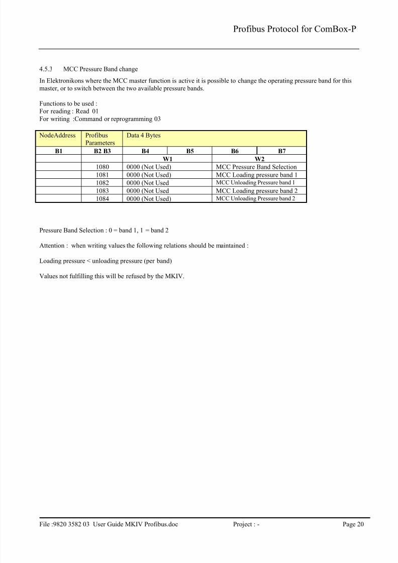
4.5.3 MCC Pressure Band change
In Elektronikons where the MCC master function is active it is possible to change the operating pressure band for this
master, or to switch between the two available pressure bands.
Functions to be used :
For reading : Read 01
For writing :Command or reprogramming 03
NodeAddress ProfibusParameters
Data 4 Bytes
B1 B2 B3 B4 B5 B6 B7
W1 W2
1080 0000 (Not Used) MCC Pressure Band Selection
1081 0000 (Not Used) MCC Loading pressure band 1
1082 0000 (Not Used MCC Unloading Pressure band 1
1083 0000 (Not Used MCC Loading pressure band 2
1084 0000 (Not Used) MCC Unloading Pressure band 2
Pressure Band Selection : 0 = band 1, 1 = band 2
Attention : when writing values the following relations should be maintained :
Loading pressure < unloading pressure (per band)
Values not fulfilling this will be refused by the MKIV.

7/23/2019 Profibus MKIV CPrev01
http://slidepdf.com/reader/full/profibus-mkiv-cprev01 22/28
Profibus Protocol for ComBox-P
File :9820 3582 03 User Guide MKIV Profibus.doc Project : - Page 21
4.6 Profibus parameters for remote control
4.6.1 Control Commands
4.6.1.1 Compressor Control Mode SelectionThe Elektronikon MkIV has a number of control modes that define the behaviour of a compressor in relation to externalinputs (pressure reading, start/stop commands,…).
Each mode has a main type (= number 1 to 4), and a sub-type (a,b,c,..). The number of sub-types is different for each main
type.
When Profibus has to be used to control a compressor the main type ust be set to 4 (=remote control over communication
line). This has to be done through the display, select “LAN Control”. By default the compressor will then enter the “4a”mode.
Through Profibus it is now possible to activate the other sub-types.
Functions to be used :
For writing :Command or reprogramming 03
NodeAddress Profibus
Parameters
Data 4 Bytes
B1 B2 B3 B4 B5 B6 B7
00 00 00 Value
ProfibusParameters
Value to write Description Accepted in mode
2001 1 Switch from 4a or 4c to 4b 4a – 4c
2 Switch from 4b or 4c to 4a 4b
3 Switch from 4a or 4b to 4c 4a – 4b
Note
Mode 4a : remote control of start/stop but pressure control is done by the controller Mode 4b : remote control of start/stop and pressure control is done from remote (Supervisory control) (also for VSD
setpoint control)
Mode 4c : remote control of start/stop with external speed (only vsd) speed control)
4.6.1.2 Compressor Commands
The commands that are described here are only available in the defined Compressor Control Modes.Carefully consult the control concept of the compressors before using them.
Functions to be used :For writing :Command or reprogramming 03
Profibus address Value to write Command Accepted in mode
2000 1 Start 4a / 4b
2 Stop 4a / 4b
3 Load 4a / 4b
4 Unload 4b ( in 4a = Manual unload )
5 MCC Start System 4a / 4d
6 MCC Stop System 4d
7 MCC Local 4d
2003 1 Reset Shutdown In all Modes
2 Reset Start Failures In all Modes

7/23/2019 Profibus MKIV CPrev01
http://slidepdf.com/reader/full/profibus-mkiv-cprev01 23/28
Profibus Protocol for ComBox-P
File :9820 3582 03 User Guide MKIV Profibus.doc Project : - Page 22
4.6.2 VSD – external setpoint/speed control
On VSD units extended external control is possible whereby either the main motor speed of the pressure set point is
directly controlled from remote over Profibus.This can be done with the following Profibus parameters.
Functions to be used :
For reading : Read 01
For writing :Command or reprogramming 03
NodeAddress Profibus
Parameters
Data 4 Bytes
B1 B2 B3 B4 B5 B6 B7
W1 W2
1070 0000 (Not Used) External Setpoint
1071 0000 (Not Used) External Speed
4.6.3 Reset Initial Settings (Analogue , Digital , Counter Inputs)
Functions to be used :
For writing :Command or reprogramming 03
NodeAddress Profibus
Parameters
Data 4 Bytes
B1 B2 B3 B4 B5 B6 B7W1 W2
Existing Node 2100 0000 (Not Used) 0000 (Not Used)

7/23/2019 Profibus MKIV CPrev01
http://slidepdf.com/reader/full/profibus-mkiv-cprev01 24/28
Profibus Protocol for ComBox-P
File :9820 3582 03 User Guide MKIV Profibus.doc Project : - Page 23
4.7 Error Code for Data Record
Node Address Parameter ID Data
B1 B2 B3 B4 …. B7
When the highest bit of the Node Address is Set to 1, then there is an error in the Data Record.
The Error Code will be find in the Data of the Data Record.
Error Code Explanation
1 Node Address Not Found
2 Profibus Parameter Not Exist
3 MCC Not Found
4 Command Not Exist
5 Data For Compressor is Not Valid (Check Cable)
6 Command not accepted because previous command not yet
executed.7 Reprogramming not accepted because previous
reprogramming not yet executed.

7/23/2019 Profibus MKIV CPrev01
http://slidepdf.com/reader/full/profibus-mkiv-cprev01 25/28
Profibus Protocol for ComBox-P
File :9820 3582 03 User Guide MKIV Profibus.doc Project : - Page 24
5 Appendix A
5.1 GSD file example
#Profibus_DP
Model_Name = "Profi2Can"
Revision = "0.00"Ident_Number = 0x0008
Protocol_Ident = 0Station_Type = 0
FMS_supp = 0Hardware_Release = "A01"Software_Release = "Z01"
9.6_supp = 1
19.2_supp = 193.75_supp = 1187.5_supp = 1
500_supp = 11.5M_supp = 13M_supp=16M_supp=112M_supp=1
MaxTsdr_9.6 = 60
MaxTsdr_19.2 = 60MaxTsdr_93.75 = 60MaxTsdr_187.5 = 60MaxTsdr_500 = 100
MaxTsdr_1.5M = 150
MaxTsdr_3M=250MaxTsdr_6M=450MaxTsdr_12M=800
Redundancy = 0Repeater_Ctrl_Sig = 224V_Pins = 0
;--Slave spezifische Werte-----
Freeze_Mode_supp = 1Sync_Mode_supp = 1
Auto_Baud_supp = 1Set_Slave_Add_supp = 0User_Prm_Data_Len = 0
Min_Slave_Intervall = 20
Modular_Station = 1Max_Module = 32Max_Input_Len = 32Max_Output_Len = 32
Max_Data_Len = 64
; Module wort-organisiert mit Sende- und Empfangsdaten
Module = "16 bytes input" 0x1F
EndModuleModule = "16 bytes output" 0x2FEndModule

7/23/2019 Profibus MKIV CPrev01
http://slidepdf.com/reader/full/profibus-mkiv-cprev01 26/28
Profibus Protocol for ComBox-P
File :9820 3582 03 User Guide MKIV Profibus.doc Project : - Page 25
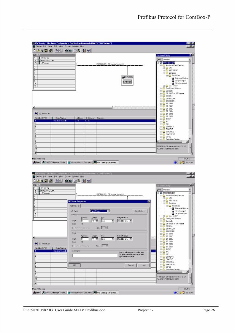
5.2 Configuration Example
ComBox - PProfibus DP Master
Simatic S7-300
CPU 315-2 DP
7/23/2019 Profibus MKIV CPrev01
http://slidepdf.com/reader/full/profibus-mkiv-cprev01 27/28
Profibus Protocol for ComBox-P
File :9820 3582 03 User Guide MKIV Profibus.doc Project : - Page 26

7/23/2019 Profibus MKIV CPrev01
http://slidepdf.com/reader/full/profibus-mkiv-cprev01 28/28
Profibus Protocol for ComBox-P