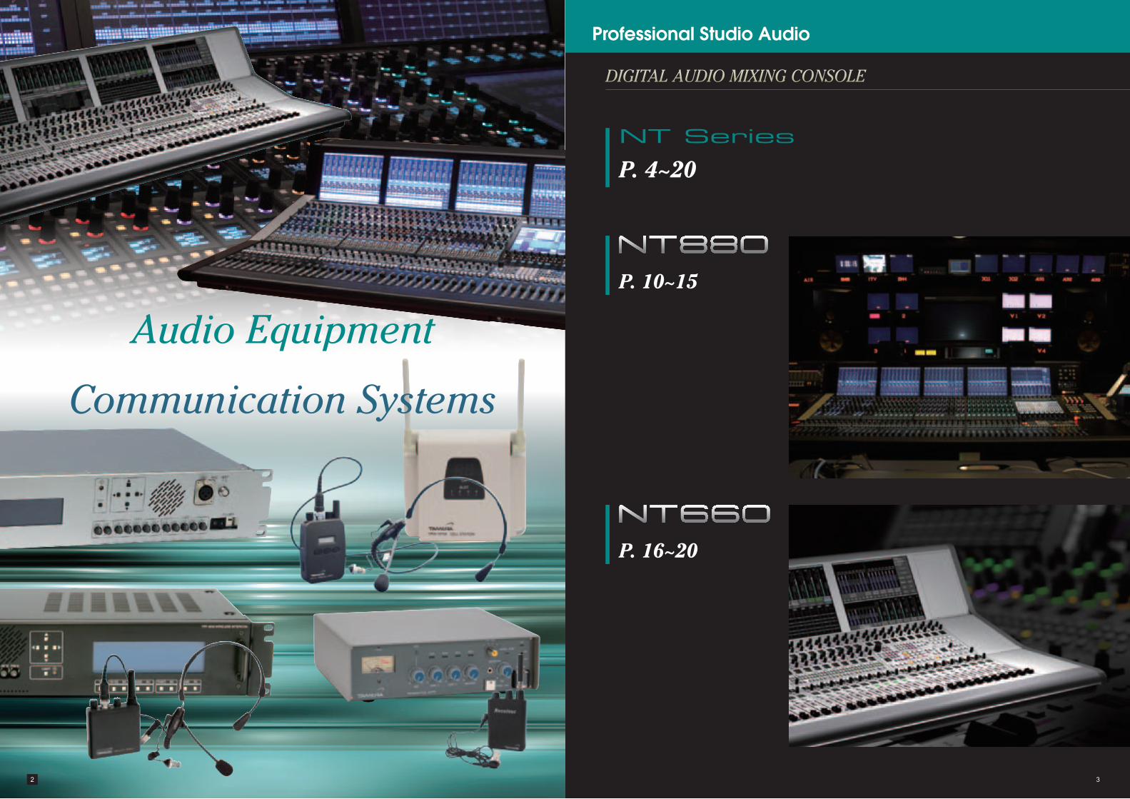
Professional Studio Audio - タムラ製作所 · Professional Studio Audio P. 10~15 P. 4~20 ......
23
Professional Studio Audio English
Transcript of Professional Studio Audio - タムラ製作所 · Professional Studio Audio P. 10~15 P. 4~20 ......
Professional Studio Audio
English
2 3
Audio Equipment
Communication Systems
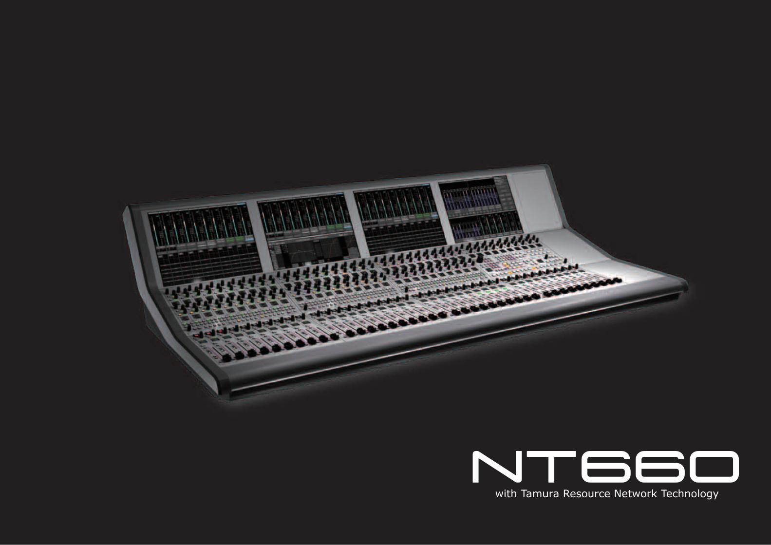
DIGITAL AUDIO MIXING CONSOLE
Professional Studio Audio
P. 10~15
P. 4~20
NT Series
P. 16~20

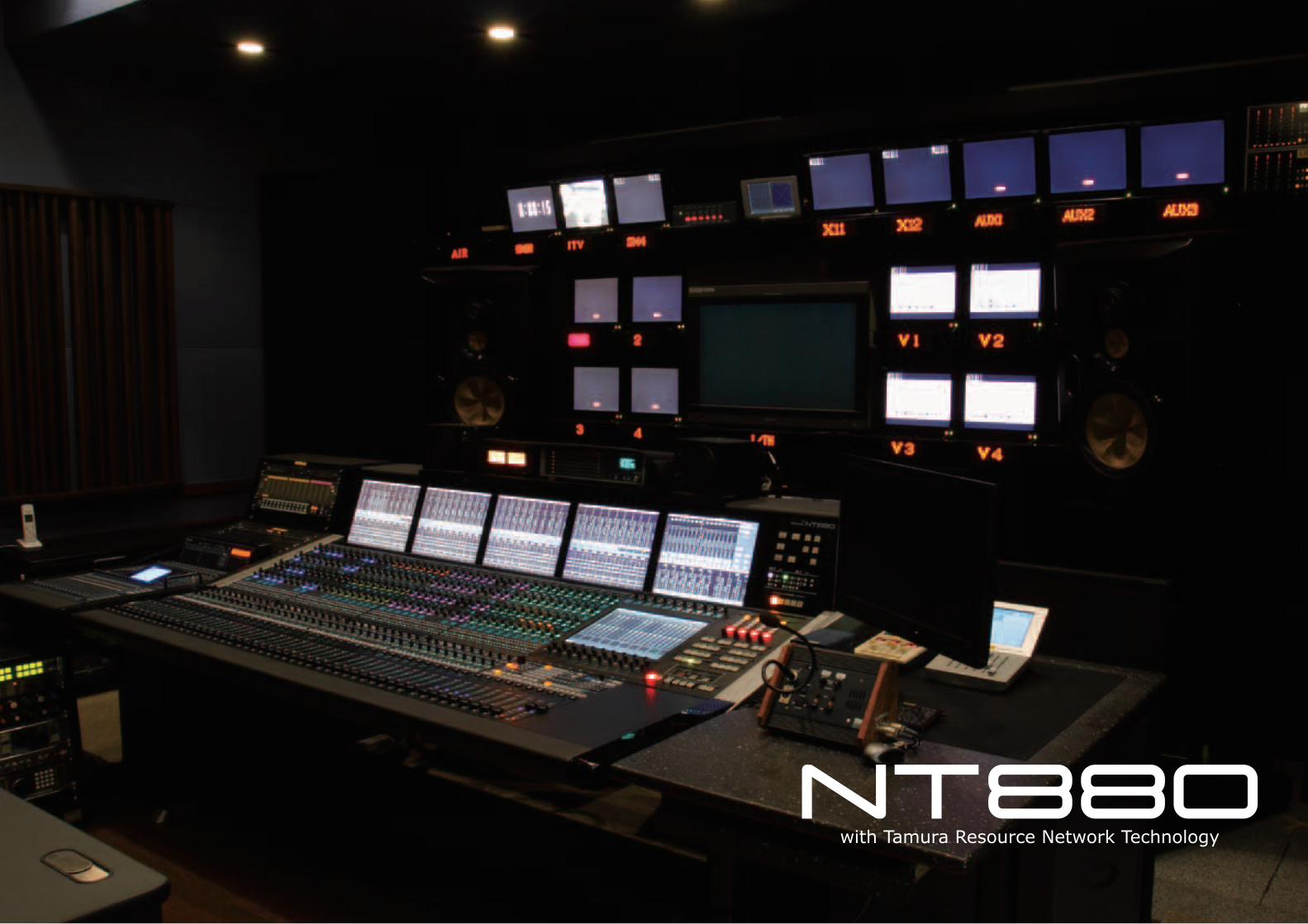
Tamura Resource Network Technology
The ocean is where life began and evolved.
It is said that all life forms were born in the ocean and some of them
returned to the ocean at the end of the cycle of their evolution.
The concept of the NT series is to be the starting point of professional creative work
that can constantly evolve and to continue to be like the ocean, a place for evolution.
Stu
dio
A
Studio B
to Router to Router
High-speed data transmission protocol TR-LINK
Simplified connections between units
A single-mode optical fiber cable is used for TR-LINK.In addition to 512-channel audio signals, synchronous and control signals are transmitted via a single optical fiber cable.Therefore, the synchronous signal cable and control signal cable, which were conventionally required for each unit along with the audio cable, are no longer required, and the units are connected to each other using a pair of optical fiber cables only.
Easy maintenance
Separation of units
32-bit floating point data transmission
MADI was previously used for connections between the I/O unit and the audio processing unit. MADI performs 24-bit fixed point data transmissions, however, and even if the DSP core performs high-precision arithmetic operation, some data loss is unavoidable owing to data transmission using MADI.When using TR-LINK, on the other hand, all audio data are transmitted in a 32-bit floating point data state.Thus, as long as the I/O unit is connected to DSP via TR-LINK, regardless of the distance between them, there will be no data loss at all, as if these units are connected in a single cabinet.Analog audio signals to be input to the I/O unit are converted into 32-bit signals in the I/O unit, whereas analog audio signals to be output from the Line-out card are directly converted into analog audio signals from 32-bit signals in the I/O unit.
A massive volume of data is sent and received between the DSP module and the routing module, and a mutual connection via the backplane inside the same cabinet was the only method used in the past. When the above method is used, all modules are put in an electrically connected state. Therefore, it was not possible to completely eliminate the risk of a trouble occurring in a single module affecting the other modules.On the other hand, using TR-LINK, which can transmit 512-channel audio data in a 32-bit floating point data state, the data can now be transmitted between modules using an optical fiber cable. As a result, the DSP module and routing module can be installed as completely separate units.The units are completely electrically separated from each other and thus it is possible to minimize the risk of a trouble occurring in a single unit affecting the entire system.
Maintenance of the router unit and DSP core, which form the heart of the system, is performed by unit-wise replacement instead of the more troublesome replacement of a circuit board. Because connections between the units are made using optical fiber cables only, a faulty unit can be replaced even when the system is operating. Connecting and disconnecting an optical fiber cable while the system is operating does not affect the system operation.
Hybrid Audio Processing
Higher integrated processor Higher integrated circuit with 44-bit high-precision arithmetic operation capacity
The NT series adopts TAMURA’s own hybrid audio processing system using the DSP and the FPGA.The combined use of superior features of both these devices significantly improves the arithmetic operation capacity and provides a higher integrated processor with high processing performance for the NT series.The entire system has been significantly downsized, for example, a 1U-size DSP unit can perform 256-channel audio signal processing.Power consumption has also been considerably reduced compared with conventional systems because of higher integrated circuits and a downsized system.
TAMURA has developed a new algorithm that can perform a 44-bit floating-point arithmetic operation for function such as an equalizer for which sound quality is particularly important. The distortion produced by deviation is reduced by increasing the accuracy of the arithmetic coefficient, making it possible to achieve an unprecedentedly clear and transparent sound quality.
Availability and fault tolerance
Hot standby system
High-speed startup
Firmware-based system
The router unit, which is a core component of the system, has a backup system that is always on hot standby. That is, exactly the same unit is in a standby state with the same operation status as that of the active unit.The standby system always stores a mirror copy of the active system’s operation status. Therefore, switching to the standby system can be performed immediately.This feature minimizes the system downtime.
The NT series has been built as a firmware-based system without using general-purpose operating systems such as Windows and Linux.Because this system does not require a shutdown operation, the system can be restarted promptly at any time.Furthermore, all operations are always stored in the backup memory; therefore, the status immediately prior to shutdown is restored when the system is restarted. Even when the system is involuntarily restarted after a power trouble or other unexpected accidents, the operation status will be securely maintained.
The startup time of the entire console system from its power-off state is approximately 30 seconds.Even when a critical system error occurs and the entire system must be restarted, this feature can minimize the system downtime.
IO Sharing
Sharing of input audio
The audio input to a single I/O Frame can be shared between multiple systems.For example, you can construct a system that allows a microphone to be used in each studio from either of the two studios.This feature makes it possible to mutually use the systems at two studios for emergency backup or use one of the systems as the Premix Mixer.
Controls, such as the gain control of a microphone input shared by multiple systems, are enabled from any system.Furthermore, the control protect setting is made at any system, which enables the gain control to be performed from a specific system only.The input audio can be shared among a maximum of eight systems.
6 7

Conceptual diagram of mixing system environment
1
2
3
Ambientnoise
MIX
OUTPUT
Direct soundIndirect sound
WindowsLaptop
DSP
DSP ( Back Up)
IO
Sync 1 Sync 2
Router ( Active )
Router ( Standby )
TR-LINKEthernet
Specifications
System
Sampling frequency 48kHz / 96kHz
Routing cross point 10,240�10,240
Maximum number of signal processing channels 1,024ch
Synchronous signal Video(NTSC/PAL)Word
AES3 / AES3id
DSP CORE Maximum 5 DSP core units (including 1 backup unit)
Number of TR-Link audio channels 512ch
ROUTER
Supply voltage AC100-240V 50/60Hz
Number of TR-Link ports 20 ports
Maximum number of signal processing channels 1,024ch
Synchronous signal input connector BNC connector x 2XLR connector x 2
DSP CORE
Supply voltage AC100-240V 50/60Hz
Number of signal processing channels 256ch
IO FRAME
Supply voltage AC100-240V 50/60Hz
Number of installed slots 14 slots
IO cards 8ch Dsub MIC/LINE IN card
8ch BNC AES IN card
HD-SDI card
8ch Dsub LINE OUT card
8ch BNC AES OUT card
MADI IO card
GPIO card
Connection diagram
AUTOMIX function
The AUTOMIX function of NT series models automates some of the mixing operations.In broadcast and content production that use several microphones, an audio mixing engineer must accurately and immediately control the fader for multiple microphone channels depending on the situation.The AUTOMIX function uses network technology to perform an automatic microphone channel fader opera-tion in an effort to lighten the load of the mixing engineer and provide environment in which the engineer can concentrate on sound quality adjustment and other tasks.
The AUTOMIX function of NT series models uses gainsharing technology to provide the following features.
(1) Makes it possible to gain a natural auditory sensation
• Produces a sound without the obvious noise gate effect.• Produces sound right from the start of a speech.• No need for mixing engineer to bother about level fluctuations.• Causes no ambience imbalances.⦆(2) No need to set a threshold level• Ambient noise during a low threshold level does not cause the gate function to activate.• High threshold levels do not cause the gate to be closed.• Even if the threshold level is set in a quiet room, it will operate properly when there is audience clapping or a musical performance.⦆(3) No need to set attack time and hold time⦆(4) No unnatural muting (no ambient) occurs even immediately after a speech has finished and the subsequent feeling of reverberation is maintained.
⦆(5) The endings of words in a speech are captured properly.
⦆(6) The quality of ambient noise does not change when a new speaker starts talking.
⦆(7) No popping noise occurs in the lower frequency range (caused by gate operation).
8 9
Main Specifications of AUTOMIX
Item SpecificationsNo. of Automix SHARC DSPs Maximum 4
Specifications
No. of Automix channels 16ch
Automix ch format Mono
Sample freq FS 48k
Connection channel
Connect ch typeHA/Line Input
GroupM1/M2/M3
Connect ch format Mono/Stereo/5.1
Connect ch signal path Depends on the insertion path
with Tamura Resource Network Technology
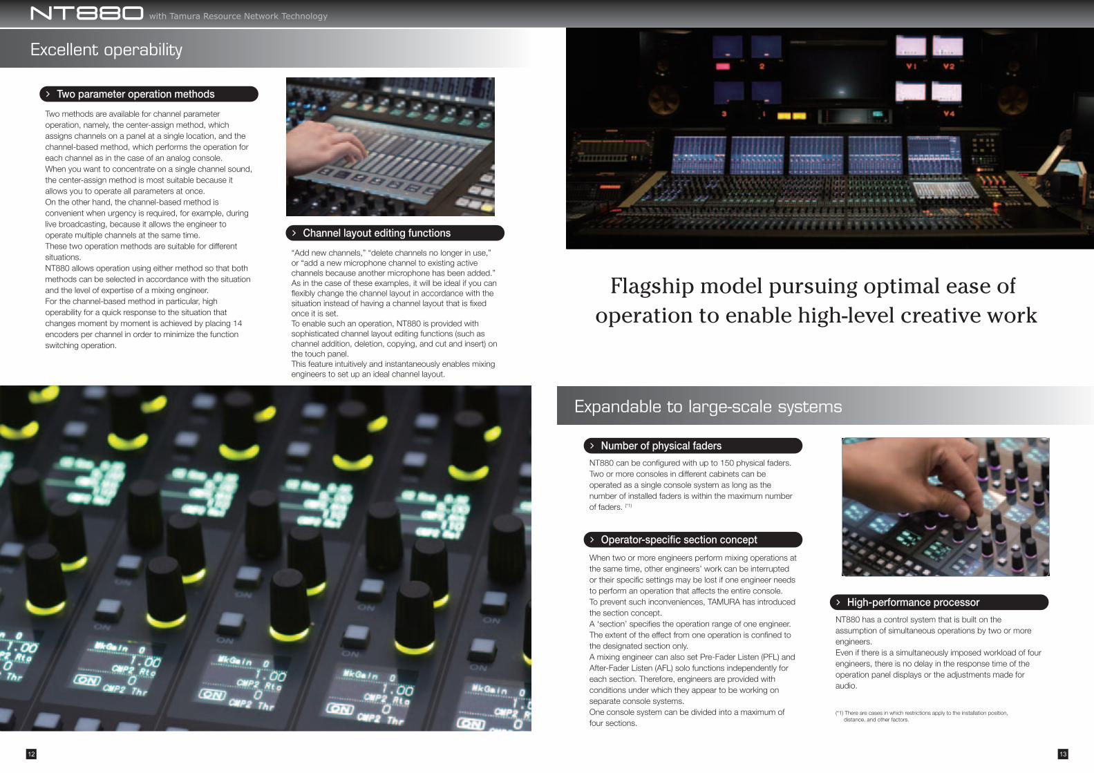
Flagship model pursuing optimal ease of operation to enable high-level creative work
Excellent operability
Expandable to large-scale systems
Two parameter operation methods
Channel layout editing functions
Number of physical faders
Operator-specific section concept
High-performance processor
(*1) There are cases in which restrictions apply to the installation position, distance, and other factors.
Two methods are available for channel parameter operation, namely, the center-assign method, which assigns channels on a panel at a single location, and the channel-based method, which performs the operation for each channel as in the case of an analog console.When you want to concentrate on a single channel sound, the center-assign method is most suitable because it allows you to operate all parameters at once.On the other hand, the channel-based method is convenient when urgency is required, for example, during live broadcasting, because it allows the engineer to operate multiple channels at the same time.These two operation methods are suitable for different situations.NT880 allows operation using either method so that both methods can be selected in accordance with the situation and the level of expertise of a mixing engineer.For the channel-based method in particular, high operability for a quick response to the situation that changes moment by moment is achieved by placing 14 encoders per channel in order to minimize the function switching operation.
“Add new channels,” “delete channels no longer in use,” or “add a new microphone channel to existing active channels because another microphone has been added.” As in the case of these examples, it will be ideal if you can flexibly change the channel layout in accordance with the situation instead of having a channel layout that is fixed once it is set.To enable such an operation, NT880 is provided with sophisticated channel layout editing functions (such as channel addition, deletion, copying, and cut and insert) on the touch panel.This feature intuitively and instantaneously enables mixing engineers to set up an ideal channel layout.
NT880 can be configured with up to 150 physical faders.Two or more consoles in different cabinets can be operated as a single console system as long as the number of installed faders is within the maximum number of faders. (*1)
NT880 has a control system that is built on the assumption of simultaneous operations by two or more engineers.Even if there is a simultaneously imposed workload of four engineers, there is no delay in the response time of the operation panel displays or the adjustments made for audio.
When two or more engineers perform mixing operations at the same time, other engineers’ work can be interrupted or their specific settings may be lost if one engineer needs to perform an operation that affects the entire console.To prevent such inconveniences, TAMURA has introduced the section concept.A ‘section’ specifies the operation range of one engineer. The extent of the effect from one operation is confined to the designated section only.A mixing engineer can also set Pre-Fader Listen (PFL) and After-Fader Listen (AFL) solo functions independently for each section. Therefore, engineers are provided with conditions under which they appear to be working on separate console systems.One console system can be divided into a maximum of four sections.
with Tamura Resource Network Technology
12 13

INPUT
1-1024
GROUP
N-1
MT
MAS
AUX
MONITOR
1-32 1/2/3(SURR)
1-48
1(SURR)2-6(ST)
1-128(N-1+MT=Max128)
1-128(N-1+MT=Max128)
MAS
PFL/AFL
MAS
GROUPAUX
AUX
N-1/MTPFL/AFL
PFL/AFL
PFL/AFL
DIR OUTEXTINS
KEYIN
INS
EXTTB
INSTB
EXTTB
EXTTB
N-1
MT
MAS
AUX
MONI
PFL
MASGROUPAUXN-1/MTPFL/AFLDIR OUT
30 Fader
40 Fader
50 Fader
60 Fader
Specifications
Audio block diagram
Dimension
Audio control parameters
HA Gain +10dBu~-64dBu
Trim +24dB~-24dB
Delay 5000ms or more
Filter Filter1 (HPF/Notch)Filter2 (LPF/Notch)
Equalizer 4Band(Support for all frequency bands)
Dynamics Compressor 2 channelsGate/Expander 1channel
Console
Supply voltage AC100-240V 50/60Hz
Maximum number of physical faders 150 faders
Bank / Layer 6Bank / 2Layer
Number of fader groups 32Group
Audio channel (Fs=48kHz)
Master Bus Maximum 24 buses(3 surround)
Group Bus Maximum 32 buses
Aux Bus Maximum 48 buses
N-1 / MT Bus Maximum 128 buses
AFL 1 surround
AFL / PFL 3 stereo
PFL 1 stereo
Main Monitor 1 surround+stereo
Sub Monitor 5 channels (Stereo)
with Tamura Resource Network Technology
14 15
Flexible Operation
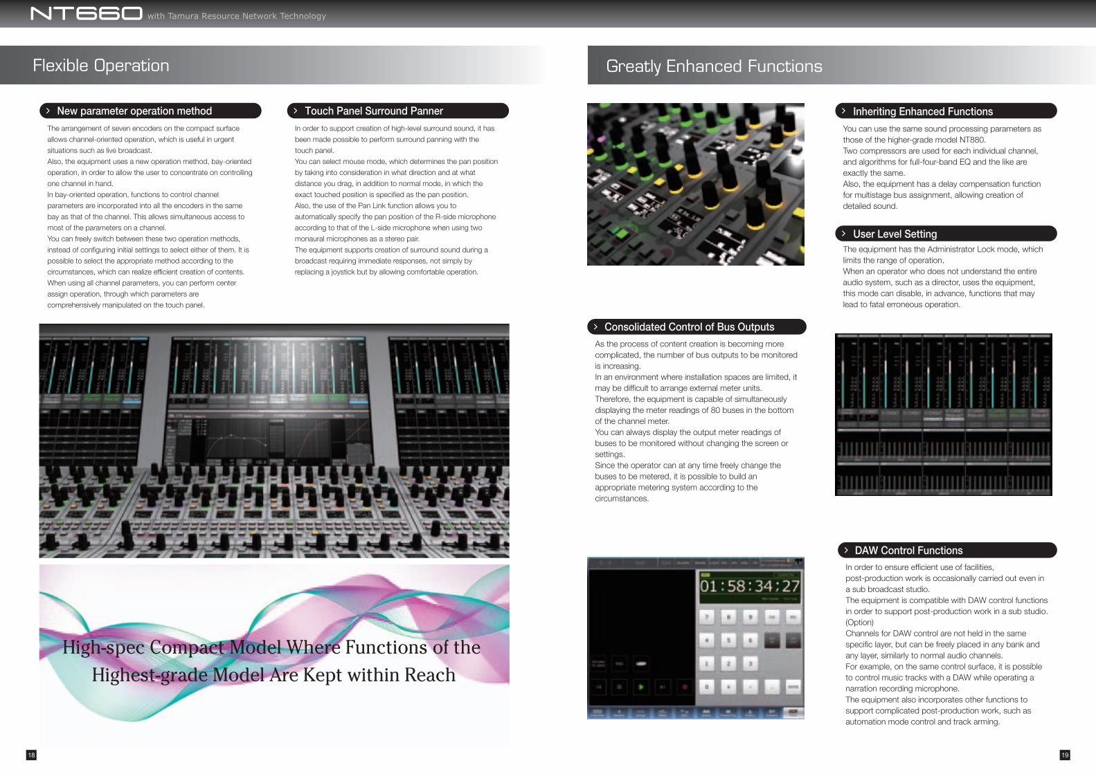
New parameter operation methodThe arrangement of seven encoders on the compact surface
allows channel-oriented operation, which is useful in urgent
situations such as live broadcast.
Also, the equipment uses a new operation method, bay-oriented
operation, in order to allow the user to concentrate on controlling
one channel in hand.
In bay-oriented operation, functions to control channel
parameters are incorporated into all the encoders in the same
bay as that of the channel. This allows simultaneous access to
most of the parameters on a channel.
You can freely switch between these two operation methods,
instead of configuring initial settings to select either of them. It is
possible to select the appropriate method according to the
circumstances, which can realize efficient creation of contents.
When using all channel parameters, you can perform center
assign operation, through which parameters are
comprehensively manipulated on the touch panel.
In order to support creation of high-level surround sound, it has
been made possible to perform surround panning with the
touch panel.
You can select mouse mode, which determines the pan position
by taking into consideration in what direction and at what
distance you drag, in addition to normal mode, in which the
exact touched position is specified as the pan position.
Also, the use of the Pan Link function allows you to
automatically specify the pan position of the R-side microphone
according to that of the L-side microphone when using two
monaural microphones as a stereo pair.
The equipment supports creation of surround sound during a
broadcast requiring immediate responses, not simply by
replacing a joystick but by allowing comfortable operation.
As the process of content creation is becoming more complicated, the number of bus outputs to be monitored is increasing.In an environment where installation spaces are limited, it may be difficult to arrange external meter units.Therefore, the equipment is capable of simultaneously displaying the meter readings of 80 buses in the bottom of the channel meter.You can always display the output meter readings of buses to be monitored without changing the screen or settings.Since the operator can at any time freely change the buses to be metered, it is possible to build an appropriate metering system according to the circumstances.
In order to ensure efficient use of facilities, post-production work is occasionally carried out even in a sub broadcast studio.The equipment is compatible with DAW control functions in order to support post-production work in a sub studio. (Option)Channels for DAW control are not held in the same specific layer, but can be freely placed in any bank and any layer, similarly to normal audio channels.For example, on the same control surface, it is possible to control music tracks with a DAW while operating a narration recording microphone.The equipment also incorporates other functions to support complicated post-production work, such as automation mode control and track arming.
You can use the same sound processing parameters as those of the higher-grade model NT880.Two compressors are used for each individual channel, and algorithms for full-four-band EQ and the like are exactly the same.Also, the equipment has a delay compensation function for multistage bus assignment, allowing creation of detailed sound.
The equipment has the Administrator Lock mode, which limits the range of operation.When an operator who does not understand the entire audio system, such as a director, uses the equipment, this mode can disable, in advance, functions that may lead to fatal erroneous operation.
Touch Panel Surround Panner
Greatly Enhanced Functions
Inheriting Enhanced Functions
User Level Setting
Consolidated Control of Bus Outputs
DAW Control Functions
High-spec Compact Model Where Functions of the Highest-grade Model Are Kept within Reach
with Tamura Resource Network Technology
18 19
40 Fader20 Fader
50 Fader
30 Fader
Specifications
Console
Audio channels (Fs=48kHz)
Audio control parameters
HA Gain +10dBu~-64dBu
Trim +24dB~-24dB
Delay 5000ms or more
Filter Filter1 (HPF/Notch)Filter2 (LPF/Notch)
Equalizer 4Band(Support for all frequency bands)
Dynamics Compressor 2 channelsGate/Expander 1channel
Supply voltage AC100-240V 50/60Hz
Maximum number of physical faders 20/30/40/50 faders
Bank / Layer 6Bank / 2Layer
Number of fader groups 32Group
Master Bus Maximum 24 buses(3 surround)
Group Bus Maximum 32 buses
Aux Bus Maximum 48 buses
N-1 / MT Bus Maximum 128 buses
AFL 1 surround
AFL / PFL 3 stereo
PFL 1 stereo
Main Monitor 1 surround+stereo
Sub Monitor 3 channels (Stereo)
Dimension
with Tamura Resource Network Technology
20 21
Communication System
INDEX
Digital Wireless Intercom SystemP. 24~33
Analog Wireless Intercom SystemP. 34~38
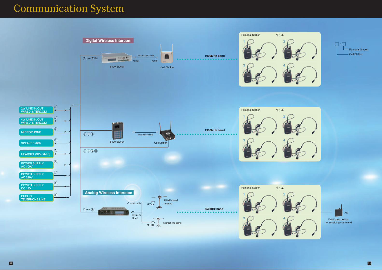
Digital Wireless Intercom
Analog Wireless Intercom
Microphone cable
XLR3P XLR3P
Base Station
Base Station
Cell Station
Cell Station
Dedicated cable
450MHz band
1900MHz band
1900MHz band
□:□Personal Station
Cell Station
Dedicated device for receiving commandMicrophone stand
Antenna410MHz band
M Type
M Type
Coaxial cable
M Type×2(1mw)
①~⑥
②⑧⑨
①②⑤⑧
①~⑦⑨
4W LINE IN/OUTWIRED INTERCOM
MICROPHONE
SPEAKER (8Ω)
HEADSET (SP) / (MIC)
POWER SUPPLYAC 100V
POWER SUPPLYAC 240V
POWER SUPPLYDC 12V
PUBLICTELEPHONE LINE
2W LINE IN/OUTWIRED INTERCOM
Personal Station
Personal Station
Personal Station
×N
1 : 4
1 2
3 4
1 : 4
1 2
3 4
1 : 4
1 2
3 4
22 23
①
②
③
④
⑤
⑥
⑦
⑧
⑨
Communication System
Microphone volume odjustment volumeMonitor speaker volume odjustment volume
Monitor speaker
Power supply indicator
Power switch
Microphoneinput connector
HYB1unit
HYB2unit CS control unit
Independent telephone line(Modular jack)
PGM inputunit
AC100~240V power supplyinput connector
(CS D) (CS C) (CS B) (CS A)
Test originating/receiving jack
Line levelodjustment volume
Side toneodjustment volume
PGM volume odjustment volume
Display panel(LCD) Back light switch
SP jackSynchronization unit(IN/OUT)
Studio floor
Performer anteroom area
感電に注意
SHOCK
WARNING 警告
ELECTRIC
AC100-240V 50/60Hz
AC100V 150VA
AC240V 240VA
MADE IN JAPAN
DCL SYSTEM
BS YFF-1870
A07-0294001T
No.
FUSE
DU-7127
SP/TEL
SP
TEL
1
2
DU-7126
PGM IN
CS A CS B CS C CS D HYB 1 HYB 2
HYB
4W
IN
ONOFFTERM
DU-7124
PUSH
4W
OUT
2W
HYB
ON
2W
DU-7124
PUSH
4W
OUT
TERM
4W
IN
OFF
IN
PU
SH
OUT
DU-7125
CPU/SYNC.
DU−7123
OUT
(DC OUT)
PU
SH
DU−7123
OUT
(DC OUT)
PU
SH
DU−7123
OUT
(DC OUT)
PU
SH
DU−7123
OUT
(DC OUT)
PU
SH
CS CS CS CS
PUSH
100-120V 250V/1.5A
220-240V 250V/1A
100–240V AC
OUT
YFF-1870
BASE STATION
TEST
H.S
MIC
POWERMIC PGMSP IN OUT BAL.T.BINPGMT.B BAL.
430±2
424±2
480±2
50±
176
.2±
188
±1
462±2460±2
250±
24.
2
LIGHT
LINE1 LINE2
12
76
24 25
Standard System
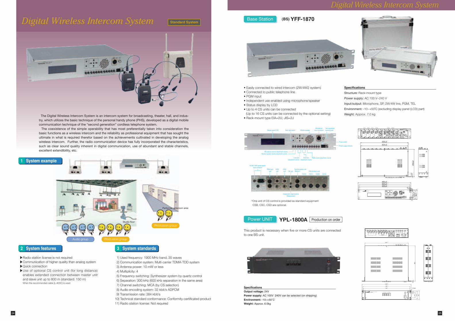
The Digital Wireless Intercom System is an intercom system for broadcasting, theater, hall, and indus-try, which utilizes the basic technique of the personal handy phone (PHS), developed as a digital mobile communication technique of the “second generation” cordless telephone system. The coexistence of the simple operability that has most preferentially taken into consideration the basic functions as a wireless intercom and the reliability as professional equipment that has sought the ultimate in what is required therefor based on the achievements cultivated in developing the analog wireless intercom. Further, the radio communication device has fully incorporated the characteristics, such as clear sound quality inherent in digital communication, use of abundant and stable channels, excellent extendibility, etc.
1)Usedfrequency:1900MHzband,35waves 2)Communicationsystem:Multi-carrierTDMA-TDDsystem 3)Antennapower:10mWorless 4)Multiplicity:4 5)Frequencyswitching:Synthesizersystembyquartzcontrol 6)Separation:300kHz(600kHzseparationinthesamearea) 7)Channelswitching:MCA(byCSselection) 8)Audioencodingsystem:32kbit/sADPCM 9)Transmissionrate:384kbit/s10)Technicalstandardconformance:Conformity-certificatedproduct11)Radiostationlicense:Notrequired
▲
Radiostationlicenseisnotrequired▲ �
Communicationofhigherqualitythananalogsystem▲
Quickconnection▲ �
UseofoptionalCScontrolunit (for longdistance)enablesextendedconnectionbetweenmasterunitandslaveunitupto800m(standard:150m)Whentherecommendedcable[L-4E5C]isused
Digital Wireless Intercom System
System example1
System features2 System standards3
Audiogroup Productiongroup
Productiongroup
*OneunitofCScontrolisprovidedasstandardequipment
CSB,CSC,CSDareoptional.
SpecificationsOutput voltage: 24VPower supply: AC 100V 240V can be selected (on shipping)Environment: -10~+50˚CWeight: Approx. 6.0kg
Digital Wireless Intercom System
(BS) YFF-1870
•Easilyconnectedtowiredintercom(2W/4W2system)•Connectedtopublictelephoneline•PGMinput•Independentuseenabledusingmicrophone/speaker•StatusdisplaybyLCD•Upto4CSunitscanbeconnected(Upto16CSunitscanbeconnectedbytheoptionalsetting)
•Rack-mounttypeEIA=2U,JIS=2J
YPL-1800A
Base Station
SpecificationsStructure:Rack-mounttype
Power supply:AC100V~240V
Input/output:Microphone,SP,2W/4Wline,PGM,TEL
Environment:-10~+50˚C(excludingdisplaypanel(LCD)part)
Weight:Approx. 7.0kg
Power UNIT Production on order
ThisproductisnecessarywhenfiveormoreCSunitsareconnectedtooneBSunit.
Channel display
Slot display
Antenne
LINE INconnector
LINE OUTconnector
DC INconnector
TALK switch (Call switch)
BATT LED HEAD SET connector
SW & VR(Reception volume)
No.
TR
MADE IN JAPAN
DCL SYSTEMCS YRW–1870
DC12−24V 12W
A07−0294001
001IZAA1285
YRW–1870A CELL STATION
SLOT
CH
1 2 3 4
IN OUT(DC OUT)
CSNO.
DC 12~24VPUSH
4
23
153±2
40
155±
2
135±
2
225±
2
51±2
44.5
±2
Metal fittings
Connector cap
Can
be
rota
ted
thro
ugh
180˚
67.7 ±1
Color: White
95.7 ±1
127.2 ±1
25.5 ±1
Color: DIC334
Serial number
Package label
26 27
Digital Wireless Intercom System
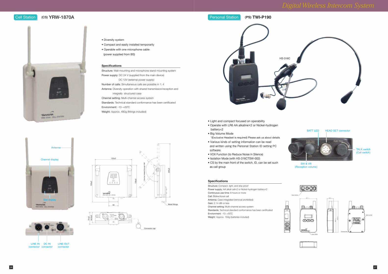
• Diversity system
• Compact and easily installed temporarily
• Operable with one microphone cable
(power supplied from BS)
Specifications
Structure:Wall-mountingandmicrophonestandmountingsystem
Power supply:DC24V(suppliedfromthemaindevice)
DC12V(externalpowersupply)
Number of calls:Simultaneouscallsarepossiblein1:4
Antenna:Diversityoperationwithsharedtransmission/receptionand
integrallystructuredcase
Channel setting:Multi-channelaccesssystem
Standards:Technicalstandardconformancehasbeencertificated
Environment:-10~+50˚C
Weight:Approx. 480g(fittingsincluded)
Cell Station (CS) YRW-1870A
SpecificationsStructure:Compact,light,anddrip-proof
Power supply:AAalkalicell×2orNickel-hydrogenbattery×2
Continuous use time:8hoursormore
Call:Bidirectionalcall
Antenna:Case-integrated(removalprohibited)
Gain:2.14dBiorless
Channel setting:Multi-channelaccesssystem
Standards:Technicalstandardconformancehasbeencertificated
Environment:-10~+50˚C
Weight:Approx. 184g(batteriesincluded)
• Light and compact focused on operability• Operate with LR6 AA alkaline×2 or Nickel-hydrogen
battery×2• Big Volume Mode
*(Exclusive Headset is required) Please ask us about details
• Various�kinds�of�setting�information�can�be�read�and�written�using�the�Personal�Station�ID�setting�PC�software.
• VOX Function (to Reduce Noise in Silence)• Isolation Mode (with HS-316CTSW-002)• CS by the main front of the switch, ID, can be set such
as call group
(PS) TWI-P190Personal Station
HS-316C
Neckband
Flexible tube(φ4)
Cable clip
Cord length 850±50Cord with connector
Coupling connectorSR30-10PQ-6P
Earphone (receiver)
Cord length 300±30
φ2.5 Earphone jack
φ3.3
φ18
111 ±
2
(R75)
Fixing screw
Microphone
28 29
Digital Wireless Intercom System
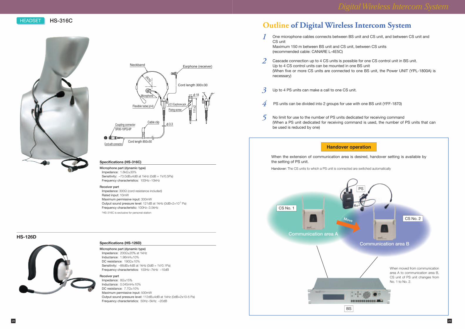
Specifications (HS-316C)
Microphone part (dynamic type)Impedance:1.6kΩ±30%Sensitivity: –73.0dB±4dBat1kHz(0dB=1V/0.5Pa)Frequency characteristics:100Hz~10kHz
Receiver partImpedance:300Ω(cordresistanceincluded)Rated input:10mWMaximum permissive input:300mWOutput sound pressure level:121dBat1kHz(0dB=2×10⁻⁵Pa)Frequency characteristic: 100Hz~3.5kHz
*HS-316Cisexclusiveforpersonalstation
HS-126D
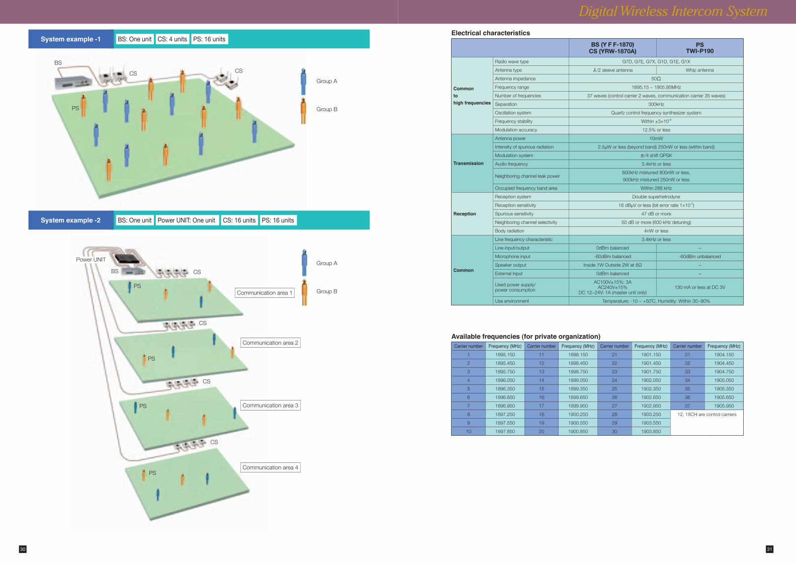
HEADSETOutline of Digital Wireless Intercom System
Handover operation
HS-316C
1
2
5
4
3
PS
When the extension of communication area is desired, handover setting is available by the setting of PS unit.
Handover: TheCSunitstowhichaPSunitisconnectedareswitchedautomatically
CS No. 1
CS No. 2
Communication area A
Communication area B
WhenmovedfromcommunicationareaAtocommunicationareaB,CSunitofPSunitchanges fromNo.1toNo.2.
BS
One microphone cables connects between BS unit and CS unit, and between CS unit and CS unitMaximum 150 m between BS unit and CS unit, between CS units (recommended cable: CANARE L-4E5C)
No limit for use to the number of PS units dedicated for receiving command (When a PS unit dedicated for receiving command is used, the number of PS units that can be used is reduced by one)
PS units can be divided into 2 groups for use with one BS unit (YFF-1870)
Up to 4 PS units can make a call to one CS unit.
Cascade connection up to 4 CS units is possible for one CS control unit in BS unit.Up to 4 CS control units can be mounted in one BS unit(When five or more CS units are connected to one BS unit, the Power UNIT (YPL-1800A) is necessary)
Move
Specifications (HS-126D)
Microphone part (dynamic type)Impedance:200Ω±20%at1kHzInductance:1.96mH±10%DC resistance:190Ω±10%Sensitivity:–86dB±4dBat1kHz(0dB=1V/0.1Pa)Frequency characteristics:100Hz~7kHz–10dB
Receiver partImpedance:8Ω±15%Inductance:0.045mH±10%DC resistance:7.7Ω±10%Maximum permissive input:500mWOutput sound pressure level:112dB±4dBat1kHz(0dB=2x10⁻⁵Pa)Frequency characteristics:50Hz~5kHz–20dB
CS
CS
CS
CS
GroupA
GroupBCommunicationarea1
Communicationarea2
Communicationarea3
Communicationarea4
PS
PS
PS
PS
Available frequencies (for private organization)Carrier number Frequency (MHz) Carrier number Frequency (MHz) Carrier number Frequency (MHz) Carrier number Frequency (MHz)
1 1895.150 11 1898.150 21 1901.150 31 1904.150
2 1895.450 12 1898.450 22 1901.450 32 1904.450
3 1895.750 13 1898.750 23 1901.750 33 1904.750
4 1896.050 14 1899.050 24 1902.050 34 1905.050
5 1896.350 15 1899.350 25 1902.350 35 1905.350
6 1896.650 16 1899.650 26 1902.650 36 1905.650
7 1896.950 17 1899.950 27 1902.950 37 1905.950
8 1897.250 18 1900.250 28 1903.250 12,18CHarecontrolcarriers
9 1897.550 19 1900.550 29 1903.550
10 1897.850 20 1900.850 30 1903.850
Electrical characteristicsBS (Y F F-1870)
CS (YRW-1870A)PS
TWI-P190
Commontohigh frequencies
Radiowavetype G7D,G7E,G7X,G1D,G1E,G1X
Antennatype λ/2sleeveantenna Whipantenna
Antennaimpedance 50ΩFrequencyrange 1895.15~1905.95MHz
Numberoffrequencies 37waves(controlcarrier2waves,communicationcarrier35waves)
Separation 300kHz
Oscillationsystem Quartzcontrolfrequencysynthesizersystem
Frequencystability Within±3×10⁻⁶
Modulationaccuracy 12.5%orless
Transmission
Antennapower 10mW
Intensityofspuriousradiation 2.5μWorless(beyondband)250nWorless(withinband)
Modulationsystem π/4shiftQPSK
Audiofrequency 3.4kHzorless
Neighboringchannelleakpower600kHzmistuned800nWorless,
900kHzmistuned250nWorless
Occupiedfrequencybandarea Within288kHz
Reception
Receptionsystem Doublesuperhetrodyne
Receptionsensitivity 16dBμVorless(biterrorrate1×10-2)
Spurioussensitivity 47dBormore
Neighboringchannelselectivity 50dBormore(600kHzdetuning)
Bodyradiation 4nWorless
Common
Linefrequencycharacteristic 3.4kHzorless
Lineinput/output 0dBmbalanced –
Microphoneinput -60dBmbalanced -60dBmunbalanced
Speakeroutput Inside1WOutside2Wat8Ω –
Externalinput 0dBmbalanced –
Usedpowersupply/powerconsumption
AC100V±15%:3AAC240V±15%
DC12~24V:1A(masterunitonly)130mAorlessatDC3V
Useenvironment Temperature;-10~+50˚C,Humidity:Within30~90%
30 31
Digital Wireless Intercom System
PowerUNIT
BS
System example -2
System example -1 CS: 4 unitsBS: One unit PS: 16 units
CSGroupA
GroupB
CSBS
PS
CS: 16 units PS: 16 unitsBS: One unit Power UNIT: One unit
Personal Station (PS)
2/4W
BATTAF part
TEL
Base Station (BS)
Cell Station (CS)
RF partCommunicationcontrol partAF partH. Set
Synchronous cable
Line input/outputWired intercom
2/4W
Line input/outputWired intercom
4W
TEL
1 2
3 4
32 33
Digital Wireless Intercom System Portable type System
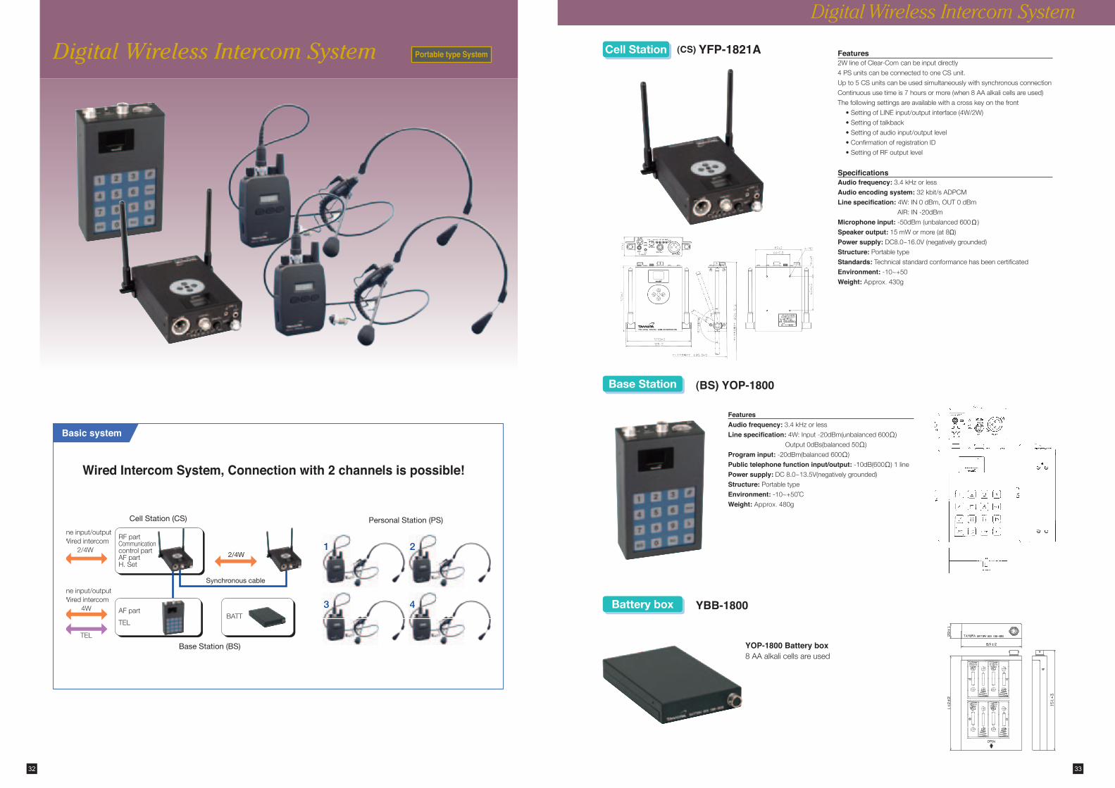
Basic system
Wired Intercom System, Connection with 2 channels is possible!
Features2WlineofClear-Comcanbeinputdirectly
4PSunitscanbeconnectedtooneCSunit.
Upto5CSunitscanbeusedsimultaneouslywithsynchronousconnection
Continuoususetimeis7hoursormore(when8AAalkalicellsareused)
Thefollowingsettingsareavailablewithacrosskeyonthefront
•SettingofLINEinput/outputinterface(4W/2W)
•Settingoftalkback
•Settingofaudioinput/outputlevel
•ConfirmationofregistrationID
•SettingofRFoutputlevel
SpecificationsAudio frequency:3.4kHzorlessAudio encoding system:32kbit/sADPCMLine specification:4W:IN0dBm,OUT0dBm
AIR:IN-20dBm
Microphone input:-50dBm(unbalanced600Ω)
Speaker output:15mWormore(at8Ω)Power supply:DC8.0~16.0V(negativelygrounded)Structure:PortabletypeStandards:TechnicalstandardconformancehasbeencertificatedEnvironment:-10~+50Weight:Approx. 430g
(CS) YFP-1821A
Digital Wireless Intercom System
Cell Station
Base Station
Battery box
(BS) YOP-1800
YBB-1800
YOP-1800 Battery box8AAalkalicellsareused
FeaturesAudio frequency:3.4kHzorlessLine specification:4W:Input-20dBm(unbalanced600Ω)
Output0dBs(balanced50Ω)
Program input:-20dBm(balanced600Ω)
Public telephone function input/output:-10dB(600Ω)1line
Power supply:DC8.0~13.5V(negativelygrounded)Structure:PortabletypeEnvironment:-10~+50˚CWeight:Approx. 480g
Monitor speaker
Microphone input connectorTest header set connector
Transmission switchReception unit switch
Squelch switch
Display panel
PGM volume adjustment volumeSide tone adjustment volumeLine level adjustment volume
Microphone volume adjustment volumeMonitor speaker volume adjustment volume
Backlight switch
FG terminal
AC 100 V power supply input connector
Fuse (3A)
External speaker jack
PGM input connector
AF mixing connector
Originating/receiving call 2W connectorOriginating/receiving call 4W connector
Line switching switch I/O interfaceAntenna connector (M type)
Main power switchPower supply indicator
Channel settingSwitch
Display switching Switch
34 35
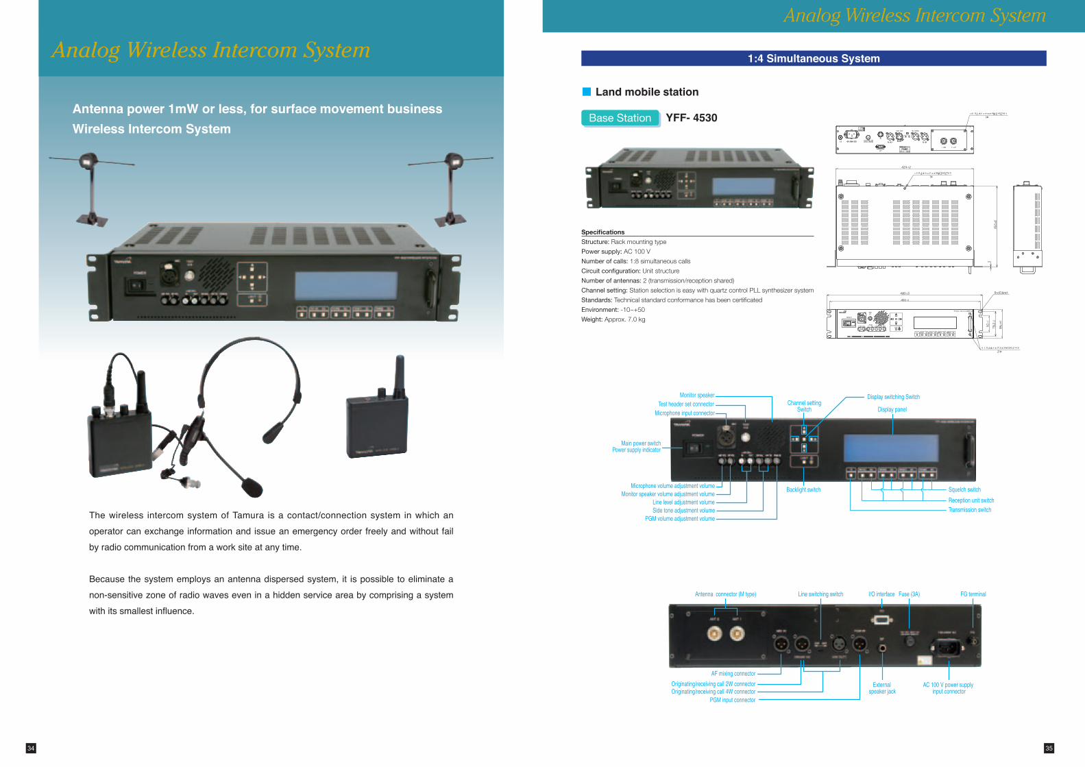
Antenna power 1mW or less, for surface movement businessWireless Intercom System
Analog Wireless Intercom System
The wireless intercom system of Tamura is a contact/connection system in which an operator can exchange information and issue an emergency order freely and without fail by radio communication from a work site at any time.
Because the system employs an antenna dispersed system, it is possible to eliminate a non-sensitive zone of radio waves even in a hidden service area by comprising a system with its smallest influence.
Analog Wireless Intercom System
1:4 Simultaneous System
YFF- 4530Base Station
■ Land mobile station
Specifications
Structure: Rackmountingtype
Power supply:AC100V
Number of calls:1:8simultaneouscalls
Circuit configuration:Unitstructure
Number of antennas:2(transmission/receptionshared)
Channel setting:StationselectioniseasywithquartzcontrolPLLsynthesizersystem
Standards:Technicalstandardconformancehasbeencertificated
Environment:-10~+50
Weight:Approx.7.0kg
85.4±2
22.5
±1
57±
582
±2
70±2
12±1
25±1
83.5±1
35±1
120±2
4±0.5
287.5±
3
50±2
91.5±3
40±2 325±10
単位:mm
TAMURANO.
DIPOLE ANTENNACAW-4510
φ56±2
2-φ4.5±1
85.4±2
22.5
±1
57±
582
±2
36 37
Analog Wireless Intercom System
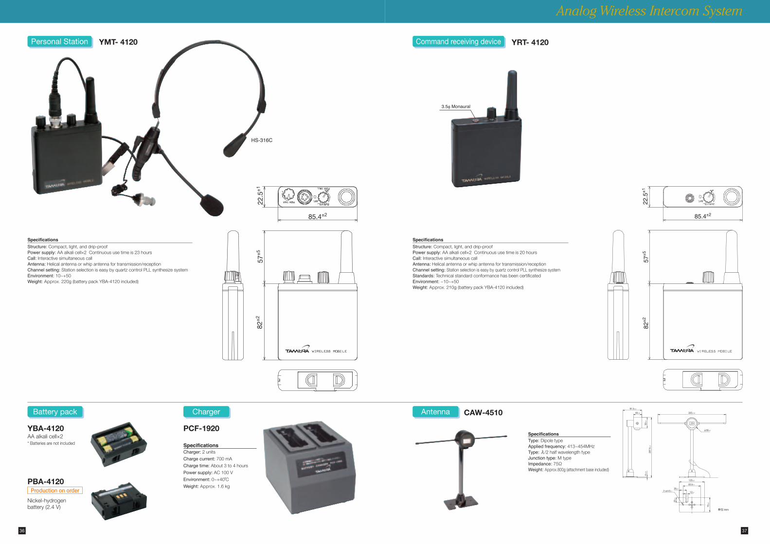
YBA-4120
PBA-4120
AAalkalicell×2
Nickel-hydrogenbattery(2.4V)
*Batteriesarenotincluded
SpecificationsStructure:Compact,light,anddrip-proofPower supply:AAalkalicell×2Continuoususetimeis23hoursCall:InteractivesimultaneouscallAntenna:Helicalantennaorwhipantennafortransmission/receptionChannel setting:StationselectioniseasybyquartzcontrolPLLsynthesizesystemEnvironment:10~+50Weight:Approx. 220g(batterypackYBA-4120included)
SpecificationsStructure:Compact,light,anddrip-proofPower supply:AAalkalicell×2Continuoususetimeis20hoursCall:InteractivesimultaneouscallAntenna:Helicalantennaorwhipantennafortransmission/receptionChannel setting:StationselectioniseasybyquartzcontrolPLLsynthesizesystemStandards:TechnicalstandardconformancehasbeencertificatedEnvironment:−10~+50Weight:Approx. 210g(batterypackYBA-4120included)
YMT- 4120Personal Station
Battery pack
Command receiving device YRT- 4120
CAW-4510Antenna
SpecificationsType:DipoletypeApplied frequency:413~454MHzType:λ/2halfwavelengthtypeJunction type:MtypeImpedance:75ΩWeight:Approx.800g(attachmentbaseincluded)
SpecificationsCharger:2units
Charge current:700mA
Charge time:About3to4hours
Power supply:AC100V
Environment:0~+40˚C
Weight:Approx. 1.6kg
Charger
Production on order
3.5f Monaural
HS-316C
PCF-1920
38
Analog Wireless Intercom System
39
FM70MHz Band Output 10 mW
Electrical characteristics
Base Station YFF-4530
Personal Station YMT-4120
Command receiving deviceYRT-4120
Frequencycommon
Radiowavetype F3E/F2D(however,useisinhibitedonlywithF2D) –
Antennatype Halfwavelengthdipoleantenna Helicalantennaorwhipantenna
Antennaimpedance 75Ω 50Ω
FrequencyrandTransmission:454MHzband,Reception:413MHzband
Transmission:413MHzband,Reception:454MHzband
Reception:454MHzband
Numberoffrequencies Downward(masterunittransmission):24waves,upward(slaveunit)72waves
Separation 12.5kHz(Interleave6.25kHz)
Oscillationsystem QuartzcontrolPLLsynthesizersystem
Frequencystability Within±4ppm
Compandercharacteristic Transmissioncompressor2:1,Receptionexpander1:2
Transmission
Antennapower Within1mW(+20-50%)Totalofantennaterminal –
Strengthintensityofspuriousradiation 2.5μWorless –
Modulationscheme Directfrequencymodulation –
Voicefrequency 3kHzorless(300Hz~3kHz) –
Neighboringchannelleakpower 60dBmorethancarrierwavepower –
OccupiedfrequencyBandwidth Within8.5kHz –
Reception
Frequencydeviation ±2.5kHzlessthanwhencarrierfrequencywithoutmodulation –
Receptionsystem Doublesuperheterodyne
Receptionsensitivity 0dBμVorlessatSINAD12dB
Squelchsensitivity ToneSQ:0dBμVorless,NoiseSQ:0dBμVorless
Cabinetradiation 4nWorless
Common
Audiofrequencycharacteristic Within300Hz~3kHz
Lineinput/output0dBm,balanced600Ω(4W)
-20dBu,unbalanced220Ω(2W)–
Microphoneinput -60dBm,balanced600Ω −60dBm,unbalanced600Ω –
SpeakeroutputInside;1W(8Ω),Outside:1W(8Ω) 15mWormore(at8Ω)
Programinput -20~+10dBmunbalanced600Ω –
Powersupplyuserange AC100V±15%:1.5AAt3.0V:150mAorless At3.0V:120mAorless
Warninglampflashesat2.3Vorless
Useenvironment Temperature:-10~+50˚C,Humidity:within35~90%
Frequency within licenseBS
Downward transmission frequencyChannelNo.
Frequency(MHz)
ChannelNo.
Frequency(MHz)
1 454.05000 2 454.05625
3 454.06250 4 454.06875
5 454.07500 6 454.08123
7 454.08750 8 454.09375
9 454.10000 10 454.10625
11 454.11250 12 454.11875
13 454.12500 14 454.13125
15 454.13750 16 454.14375
17 454.15000 18 454.15625
19 454.16250 20 454.16875
21 454.17500 22 454.18125
23 454.18750 24 454.19375
PSUpward transmission frequency
ChannelNo.
Frequency(MHz)
ChannelNo.
Frequency(MHz)
1 413.70000 2 413.70625
3 413.71250 4 413.71875
5 413.72500 6 413.73125
7 413.73750 8 413.74375
9 413.75000 10 413.75625
11 413.76250 12 413.76875
13 413.77500 14 413.78125
15 413.78750 16 413.79375
17 413.80000 18 413.80625
19 413.81250 20 413.81875
21 413.82500 22 413.83125
23 413.83750 24 413.84375
PSUpward transmission frequency
ChannelNo.
Frequency(MHz)
ChannelNo.
Frequency(MHz)
25 413.85000 26 413.85625
27 413.86250 28 413.86875
29 413.87500 30 413.88125
31 413.88750 32 413.89375
33 413.90000 34 413.90625
35 413.91250 36 413.91875
37 413.92500 38 413.93125
39 413.93750 40 413.94375
41 413.95000 42 413.95625
43 413.96250 44 413.96875
45 413.97500 46 413.98125
47 413.98750 48 413.99375
PSUpward transmission frequency
ChannelNo.
Frequency(MHz)
ChannelNo.
Frequency(MHz)
49 414.00000 50 414.00625
51 414.01250 52 414.01875
53 414.02500 54 414.03125
55 414.03750 56 414.04375
57 414.05000 58 414.05625
59 414.06250 60 414.08875
61 414.07500 62 414.08125
63 414.08750 64 414.09375
65 414.10000 66 414.10625
67 414.11250 68 414.11875
69 414.12500 70 414.13125
71 414.13750 72 414.14375
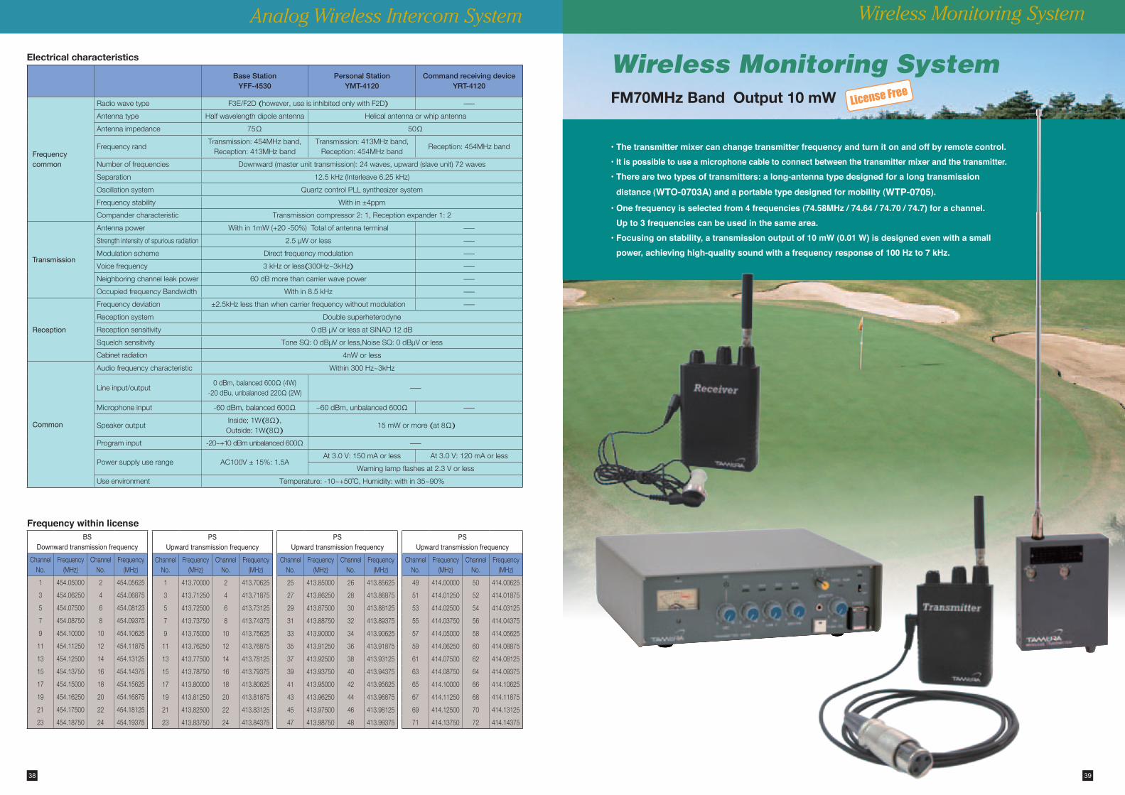
Wireless Monitoring System
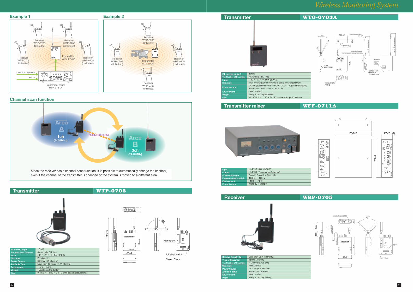
License Free
• The transmitter mixer can change transmitter frequency and turn it on and off by remote control.• It is possible to use a microphone cable to connect between the transmitter mixer and the transmitter.• There are two types of transmitters: a long-antenna type designed for a long transmission
distance (WTO-0703A) and a portable type designed for mobility (WTP-0705).
• One frequency is selected from 4 frequencies (74.58MHz / 74.64 / 74.70 / 74.7) for a channel. Up to 3 frequencies can be used in the same area.
• Focusing on stability, a transmission output of 10 mW (0.01 W) is designed even with a small power, achieving high-quality sound with a frequency response of 100 Hz to 7 kHz.
Wireless Monitoring System
45±2
22.8
80±2
19±2
60±2
180˚
Receiver
Fixing screw:PF1/2
AA alkali cell x2
Element part can be rotated through 360˚
Battery pack:YBA-4120
180±
5 (M
inim
um le
ngth
)
130±
235
±2
105±2
810±
10 (M
axim
um le
ngth
)
Expansion/contraction typerod anten
Tamper proof Torx screw
3 (M2.6x4 flat countersunk head screw) used
4 M3screw holes
260±
2
77±2 (8)250±2
AA alkali cell x1
Case : Black
Nameplate
60±2
180˚
80±
2
149±
10
19±
2
AreaA
AreaB
a
1ch(74.58MHz)
3ch(74.70MHz)
Channel scan
LINE in x 2 Systems
MIC in
Transmitter mixerWFF-0711A
ReceiverWRP-0705(Unlimited)
ReceiverWRP-0705(Unlimited)
ReceiverWRP-0705(Unlimited)
ReceiverWRP-0705(Unlimited)
TransmitterWTO-0703A Receiver
WRP-0705(Unlimited)
ReceiverWRP-0705(Unlimited)
ReceiverWRP-0705(Unlimited)
ReceiverWRP-0705(Unlimited)
TransmitterWTP-0705
40 41
Transmitter
Transmitter mixer
Transmitter
Wireless Monitoring System
Receiver WRP-0705
WTO-0703A
Rf power output 10mWThe Number of Channels 4Channels�PLL�TypeInput �–60�/�–20�/�+4�dBm�(600Ω)Structure Wall-mounting�and�microphone�stand�mounting�system
Power SourceDC10V(supplied�by�WFF-0720)��DC7~15V(External�Power)More�than�18�hours(AA�alkaline×2)
Environment –10℃~+50℃Weight 680g�(Including�batteries)Size W�:�105�×�H�:�130�×�D�:�35�(mm)�except�protuberance�
Receive Sensitivity Less�than�2μV�(SINAD12)Type of Reception Space�DiversityThe Number of Channels 4�Channels�PLL�typeStructure Portable�sizePower Source DC1.5V�(AA�alkaline)�Available Time More�than�18�HoursEnvironment –10℃~+50℃Wight 100g�(Including�Battery)
WFF-0711A
Input LINE�×2�MIC�×1(600Ω)Output LINE�×1�(Transformer�Balanced)Channel Change Remote�Control,�4�ChannelsFrequency Characteristic 100Hz�~�10kHzEnvironment –10℃~+50℃Power Source AC100V�/�DC12V
Channel scan function
Example 1 Example 2
Since the receiver has a channel scan function, it is possible to automatically change the channel, even if the channel of the transmitter is changed or the system is moved to a different area.
WTP-0705
Rf Power Output 10mWThe Number of Channels 4�channels�PLL�typeInput –60�/�–20�/�+4�dBm�(600Ω)Structure Portable�sizePower Source DC1.5V�(AA�alkaline)�Available Time More�than�10�hours�(1�AA�alkaline)Environment –10℃~+50℃Weight 100g�(Including�battery)Size W�:�60�×�H�:�80�×�D�:�19�(mm)�except�protuberance�

Memo Memo
42 43

TAMURA CORPORATIONHEAD OFFICE : Broadcom Business Unit / Sales Department 1-19-43, Higashi-Oizumi, Nerima-ku, Tokyo 178-8511 JapanTel:+81-3-3978-2242 Fax:+81-3-3978-2005 A-2028E-8
2015-10