Presby Wastewater Treatment Systems -...
35
© Copyright December 2016, Presby Environmental, Inc. All Rights Reserved. Presby Wastewater Treatment Systems Indiana Design and Installation Manual for Advanced Enviro-Septic ® , Enviro-Septic ® and Simple-Septic ® Wastewater Treatment Systems Minimizes the Expense Protects the Environment Preserves the Site Presby Environmental, Inc. 143 Airport Rd., Whitefield, NH 03598 Tel: 800-473-5298 Fax: 603-837-9864 [email protected] www.PresbyEnvironmental.com
-
Upload
trinhnguyet -
Category
Documents
-
view
212 -
download
0
Transcript of Presby Wastewater Treatment Systems -...

© Copyright December 2016, Presby Environmental, Inc. All Rights Reserved.
Presby Wastewater Treatment Systems
Indiana Design and Installation Manual
for Advanced Enviro-Septic®, Enviro-Septic® and Simple-Septic®
Wastewater Treatment Systems
Minimizes the Expense Protects the Environment Preserves the Site
Presby Environmental, Inc. 143 Airport Rd., Whitefield, NH 03598 Tel: 800-473-5298 Fax: 603-837-9864
[email protected] www.PresbyEnvironmental.com

The information in this manual is subject to change without notice. We recommend that you check your state’s page on our website on a regular basis for updated information. Your suggestions and comments are welcome. Please
contact us at: 800-473-5298
Presby Environmental, Inc. 143 Airport Road
Whitefield, NH 03598 Phone: 1-800-473-5298 Fax: (603) 837-9864
Website: www.PresbyEnvironmental.com
The products and methods depicted in this manual are protected by one or more patents. For more information: Pat. www.presbyeco.com/patents.
Advanced Enviro-Septic® is a registered trademark of Presby Environmental Inc. Enviro-Septic® is a registered trademark of Presby Environmental, Inc. Simple-Septic® is a registered trademark of Presby Environmental Inc.
IMPORTANT NOTICE: This Manual is intended ONLY for use in designing and installing Presby Environmental’s Advanced Enviro-Septic®, Enviro-Septic® and Simple-Septic® Wastewater Treatment Systems. The use of this Manual with any other product is prohibited. The processes and design criteria contained herein are based solely on our experience with and testing of Advanced Enviro-Septic®, Enviro-Septic® and Simple-Septic®. Substitution of any other large diameter gravelless pipe will result in compromised treatment of wastewater and other adverse effects.
© Presby Environmental, Inc. December 2016
All Rights Reserved
Date of Revised Issue: December 12, 2016
The Next Generation of Wastewater Treatment Technology

© Presby Environmental, Inc., Indiana Design & Installation Manual December 2016 Edition -i-
TABLE OF CONTENTS
Section Number Page Number 1.0 Background ....................................................................................................................................... 1 2.0 Ten Stages of Wastewater Treatment .............................................................................................. 2 3.0 System Components ......................................................................................................................... 3 4.0 Introduction ........................................................................................................................................ 3 5.0 Design Criteria................................................................................................................................... 4 6.0 Indiana State Specific Information .................................................................................................... 5 7.0 Basic Serial Distribution .................................................................................................................... 8 8.0 Combination Serial Distribution ......................................................................................................... 9 9.0 Butterfly Configuration ..................................................................................................................... 10 10.0 Curved Beds.................................................................................................................................... 11 11.0 90° Beds .......................................................................................................................................... 11 12.0 Multiple Bed Distribution ................................................................................................................. 11 13.0 Non-Conventional System Configurations ...................................................................................... 12 14.0 Perimeter Drains ............................................................................................................................. 12 15.0 Table A – Presby Pipe Required ..................................................................................................... 14 16.0 Table B - Presby Sand Bed Area (SSBA) Required ....................................................................... 14 17.0 Table C – System Sand Bed Length (SSBL) .................................................................................. 15 18.0 Table D: System Pipe Row Length and Pipe Layout Width (PLW) ................................................ 15 19.0 Design Procedure ........................................................................................................................... 15 20.0 Pumped System Requirements ...................................................................................................... 19 21.0 Venting Requirements ..................................................................................................................... 20 22.0 Site Selection .................................................................................................................................. 22 23.0 Installation Requirements, Component Handling and Site Preparation ......................................... 23 24.0 System Bacteria Rejuvenation and Expansion ............................................................................... 26 25.0 Operation & Maintenance ............................................................................................................... 27 26.0 Glossary .......................................................................................................................................... 28 27.0 Indiana System Installation Form .................................................................................................... 32

© Presby Environmental, Inc., Indiana Design & Installation Manual December 2016 Edition -1-
1.0 Background Liquid that exits from a septic tank (“effluent”) contains suspended solids that can cause traditional systems to fail prematurely. Solids can overload bacteria, cut off air required for aerobic bacterial activity, and/or seal the underlying soil, interfering with its ability to absorb liquid. By utilizing simple yet effective natural processes, the Presby Treatment System treats septic tank effluent in a manner that prevents suspended solids from sealing the underlying soil, increases system aeration, and provides a greater bacterial treatment area (“biomat”) than traditional systems. 1.1 Why Our System Excels The Presby Treatment System retains solids in its pipe and provides multiple bacterial surfaces to treat effluent prior to its contact with the soil. The continual cycling of effluent (the rising and falling of liquid inside the pipe) enhances bacterial growth. This all combines to create a unique eco-system that no other passive wastewater treatment system is designed to offer. The result is a system that excels by being more efficient, last longer, and have a minimal environmental impact. 1.2 System Advantages
a) costs less than traditional systems b) eliminates the need for washed stone c) often requires a smaller area d) installs more easily and quickly than traditional systems e) adapts easily to residential and commercial sites of virtually any size f) adapts well to difficult sites g) develops a protected receiving surface preventing sealing of the underlying soil h) blends system into sloping terrain i) increases system performance and longevity j) tests environmentally safer than traditional systems k) recharges groundwater more safely than traditional systems l) made from recycled plastic
1.3 Patented Presby Technology At the heart of Advanced Enviro-Septic®, Enviro-Septic®, or Simple-Septic® is a patented corrugated, perforated plastic pipe with interior skimmer tabs and cooling ridges. All Presby Pipe is surrounded by one or more filtering, treatment and dispersal layers (see further product descriptions below). Presby Pipes are assembled and installed in a bed of specified System Sand (IN DOT 23 sand) which can either be below the ground or above. Presby Systems are completely passive in their treatment of wastewater, requiring no electricity, motors, alarms, computers, etc. 1.4 Advanced Enviro-Septic® (AES) The Advanced Enviro-Septic® pipe is assembled into an onsite wastewater treatment system that has been successfully tested and certified to NSF 40, Class I (a certification typically given to mechanical aeration devices), BNQ of Quebec, Class I, II, III and Cebedeau, Belgium standards. Advanced Enviro-Septic® is comprised of corrugated, perforated plastic pipe, Bio-Accelerator® fabric along its bottom which is surrounded by a layer of randomized plastic fibers and a sewn geo-textile fabric. Advanced Enviro-Septic® creates an eco-system designed to simultaneously purify and disperse effluent after primary treatment by a septic tank. Advanced Enviro-Septic® is the “next generation” of our Enviro-Septic® technology. The AES product incorporates Bio-Accelerator®, a proprietary enhancement that screens additional solids from effluent, accelerates treatment processes, assures even distribution and provides additional surface area. Each foot of Advanced Enviro-Septic® provides over 40 sq ft of total surface area for bacterial activity. Caution: see para. 6.8, page 6 concerning product substitutions. 1.5 Enviro-Septic® (ES) The Enviro-Septic® pipe is assembled into an onsite wastewater treatment system. Enviro-Septic® is comprised of corrugated, perforated plastic pipe which is surrounded by a layer of randomized plastic fibers and a sewn geo-textile fabric. The system is designed to simultaneously purify and disperse effluent after primary treatment by a septic tank. Each foot of Enviro-Septic® provides over 25 sq ft of total surface area for bacterial activity. Caution: see para. 6.8, page 6 concerning product substitutions. 1.6 Simple-Septic® (SS) Simple-Septic® is a single layer geo-textile fabric distribution system after primary treatment by a septic tank. Simple-Septic® is similar to other single-layer fabric, large diameter, gravelless pipe (LDGP) systems on the market today, yet provides the added benefit of Presby's patented skimmer tabs and cooling ridges to protect the bacterial surface area of the fabric. Each foot of Simple-Septic® pipe provides over 15 sq ft of total surface area for bacterial activity. Caution: see para. 6.8, page 6 concerning product substitutions.

© Presby Environmental, Inc., Indiana Design & Installation Manual December 2016 Edition -2-
2.0 Ten Stages of Wastewater Treatment
The Presby Wastewater Treatment System's 10 STAGES OF TREATMENT
Advance Enviro-Septic® (AES), Enviro-Septic® (ES) and Simple-Septic® (SS)
Stage 1: Warm effluent enters the pipe and is cooled to ground temperature. Stage 2: Suspended solids separate from the cooled liquid effluent. Stage 3: Skimmers further capture grease and suspended solids from the existing effluent. Stage 4: Pipe ridges allow the effluent to flow uninterrupted around the circumference of the pipe and aid in
cooling. Stage 5: Bio-Accelerator® fabric screens additional solids from the effluent, enhances and accelerates treatment,
facilitates quick start-up after periods of non-use, provides additional surface area for bacterial growth, promotes even distribution, and further protects outer layers and the receiving surfaces so they remain permeable. (AES only)
Stage 6: A mat of coarse, randomly-oriented fibers separates more suspended solids from the effluent. (AES & ES only)
Stage 7: Effluent passes into the geo-textile fabrics and grows a protected bacterial surface. Stage 8: Sand wicks liquid from the geo-textile fabrics and enables air to transfer to the bacterial surface. Stage 9: The fabrics and fibers provide a large bacterial surface to break down solids. Stage 10: An ample air supply and fluctuating liquid levels increase bacterial efficiency.
SYSTEM SAND
CROSS SECTION
12
10
2EFFLUENT
SCUM
SLUDGE
CIRBAF ROTARELECCA-OI
B
AIR SPACE
®
(AES ONLY)
SEWN SEAM(ALWAYS UP)
SKIMMER TABS3
5
4
6
7
8 9
BIO-ACCELERATOR FABRIC (AES) ONLY
GEO-TEXTILE FABRIC
COARSE FIBERS(AES & ES ONLY)
RIDGES
®

© Presby Environmental, Inc., Indiana Design & Installation Manual December 2016 Edition -3-
3.0 System Components 3.1 Presby Pipe
a) Plastic pipe made with a significant percentage of recycled material b) 10 ft sections (can be cut to any length) c) Ridged and perforated, with skimmer tabs on interior d) AES is supplied with Bio-Accelerator® along bottom of the pipe (the sewn seam
indicates “this side up”). e) AES and ES are supplied with a mat of randomly-oriented plastic fibers f) Wrapped in a non-woven geo-textile fabric stitched in place g) Exterior diameter of 12 in. h) Each 10 ft section has a liquid holding capacity of approx. 58 gallons i) A 10 ft length of AES, ES or SS pipe is flexible enough to bend up to 90°
3.2 Offset Adapter An offset adapter is a plastic fitting 12 in. in diameter with a 4 in. hole designed to accept a 4 in. inlet pipe, raised connection or vent pipe. The hole is to be in the 12 o’clock position, 7 in. above bottom of the Presby Pipe. When assembling pipes into rows, note that the geo-textile fabrics are placed over the edges of the Offset Adapter and Couplings. 3.3 Coupling A coupling is a plastic fitting used to create a connection between two pieces of Presby pipe. Note that the couplings are wide enough to cover 1 or 2 pipe corrugations on each of the two pipe ends being joined. The couplings feature a snap-lock feature that requires no tools. When assembling pipes into rows, note that the geo-textile fabric does not go under couplings. Pull fabric back, install coupling, and then pull fabric over coupling. Also note, during installation in cold weather, couplings are easier to work with if stored in a heated location before use; such as a truck cab. 3.4 Raised Connection A raised connection is a PVC Sewer & Drain pipe configuration which is used to connect Presby rows. Raised connections extend 2 in. to 4 in. into pipe and are installed on an angle (as shown below). All PVC joints should be glued.
4.0 Introduction 4.1 Presby Environmental Standards All Presby Systems must be designed and installed in compliance with the procedures and specifications described in this Manual and in the product’s Indiana approval. 4.2 Indiana Rules This manual is to be used in conjunction with Rule 410 IAC 6-8.3 for residential systems, and with Rule 410 IAC 6-10.1 for commercial systems, both of which were effective on November 19, 2012. 4.3 Conflicts between Indiana Rules & Manual In the event of contradictions between this Manual and Indiana State Department of Health (ISDH) regulations, the ISDH and Presby Environmental, Inc. (800-437-5298) must be contacted for technical assistance. 4.4 Certification Requirements Any designers and installers who have not previously attended a Presby Environmental, Inc. “Certification Course” are required to obtain Presby Certification. Certification is obtained by attending a Certification Course presented by Presby Environmental, Inc. or its sanctioned representative. Certification can also be obtained by viewing tutorial videos on our website (high speed connection required) and then successfully passing a short assessment test, which is also available over the internet. All professionals involved in the inspection, review or certification of Presby Systems must also become Presby Certified.
© Presby Environmental, Inc., Indiana Design & Installation Manual December 2016 Edition -4-
4.5 Exceptions to Presby Requirements To resolve any conflicts with or exceptions to any requirements in this Manual, the ISDH and Presby Environmental, Inc. must be contacted. 4.6 Technical Support Presby Environmental, Inc. provides technical support to all individuals using our products. For questions about our products or the information contained in this Manual, or to register for a Certification Course, please contact us at 1-800-473-5298. 5.0 Design Criteria This section presents the various design configurations of the Presby System. The system configuration to be used is determined by characteristics of the receiving soils, vertical distance to the SHWT or restrictive feature, other characteristics specific to the particular site and the design daily flow. 5.1 Advanced Enviro-Septic®, Enviro-Septic® and Simple-Septic® Sizing AES, ES and SS all use the same bed sizing tables, pipe and installation requirements noted in this manual.
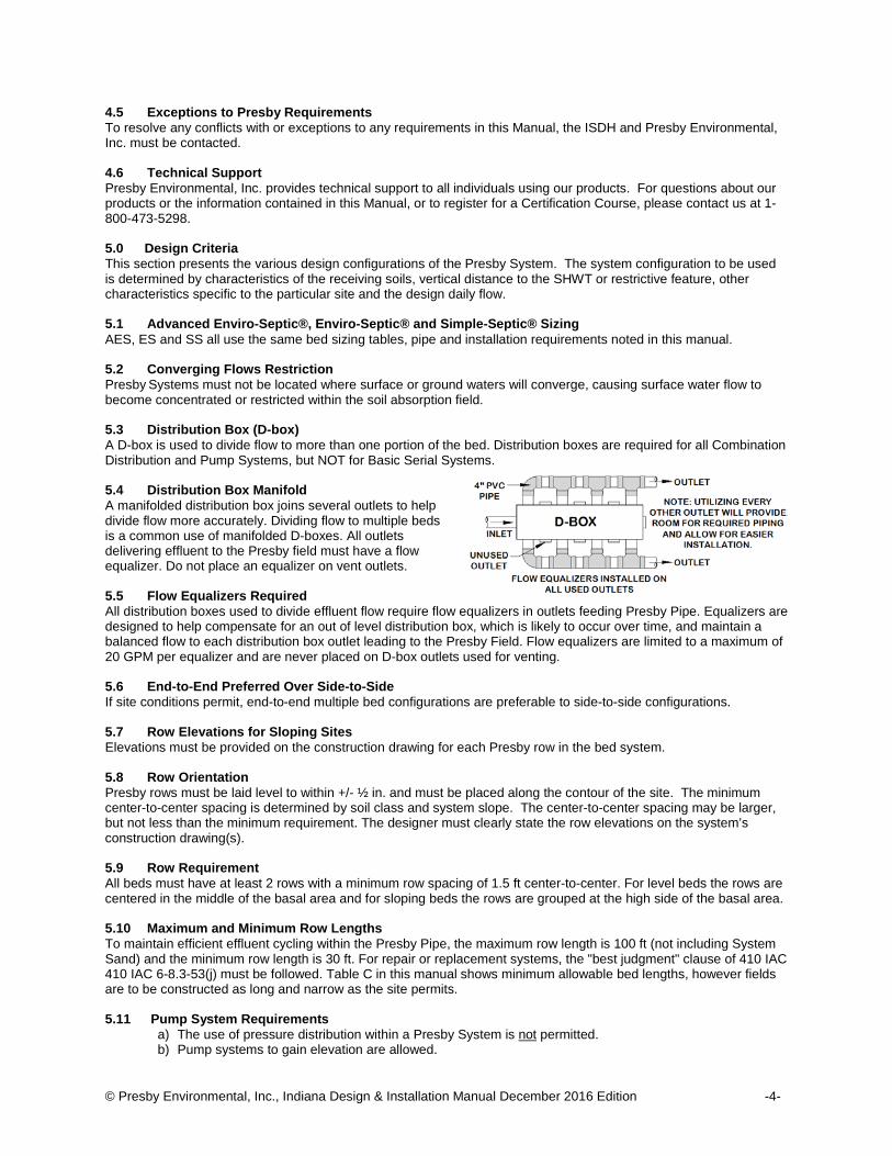
5.2 Converging Flows Restriction Presby Systems must not be located where surface or ground waters will converge, causing surface water flow to become concentrated or restricted within the soil absorption field. 5.3 Distribution Box (D-box) A D-box is used to divide flow to more than one portion of the bed. Distribution boxes are required for all Combination Distribution and Pump Systems, but NOT for Basic Serial Systems. 5.4 Distribution Box Manifold A manifolded distribution box joins several outlets to help divide flow more accurately. Dividing flow to multiple beds is a common use of manifolded D-boxes. All outlets delivering effluent to the Presby field must have a flow equalizer. Do not place an equalizer on vent outlets. 5.5 Flow Equalizers Required All distribution boxes used to divide effluent flow require flow equalizers in outlets feeding Presby Pipe. Equalizers are designed to help compensate for an out of level distribution box, which is likely to occur over time, and maintain a balanced flow to each distribution box outlet leading to the Presby Field. Flow equalizers are limited to a maximum of 20 GPM per equalizer and are never placed on D-box outlets used for venting. 5.6 End-to-End Preferred Over Side-to-Side If site conditions permit, end-to-end multiple bed configurations are preferable to side-to-side configurations. 5.7 Row Elevations for Sloping Sites Elevations must be provided on the construction drawing for each Presby row in the bed system. 5.8 Row Orientation Presby rows must be laid level to within +/- ½ in. and must be placed along the contour of the site. The minimum center-to-center spacing is determined by soil class and system slope. The center-to-center spacing may be larger, but not less than the minimum requirement. The designer must clearly state the row elevations on the system’s construction drawing(s). 5.9 Row Requirement All beds must have at least 2 rows with a minimum row spacing of 1.5 ft center-to-center. For level beds the rows are centered in the middle of the basal area and for sloping beds the rows are grouped at the high side of the basal area. 5.10 Maximum and Minimum Row Lengths To maintain efficient effluent cycling within the Presby Pipe, the maximum row length is 100 ft (not including System Sand) and the minimum row length is 30 ft. For repair or replacement systems, the "best judgment" clause of 410 IAC 410 IAC 6-8.3-53(j) must be followed. Table C in this manual shows minimum allowable bed lengths, however fields are to be constructed as long and narrow as the site permits. 5.11 Pump System Requirements
a) The use of pressure distribution within a Presby System is not permitted. b) Pump systems to gain elevation are allowed.

© Presby Environmental, Inc., Indiana Design & Installation Manual December 2016 Edition -5-
c) Systems incorporating pumps to gain elevation must use differential venting and velocity reduction to control liquid flow.
Reference: See Pump System Requirements, para. 20.0, page 19. 5.12 Septic Tank and Distribution Box Elevations The outlet of a septic tank or distribution box must be set at least 2 in. above the highest inlet of the Presby
row, with the connecting pipe slope not less than 1% (approximately 1/8 in. per foot.) 5.13 System Side Slope Tapers If a bed extends above grade, the IN DOT 23 sand and the cover soils on the system must have side slope tapers until it meets the original grade. Side slope tapering is to be no steeper than 3:1; steeper side slopes require ISDH approval. The side slope taper begins 3 ft from the Presby Pipe, measured parallel to the system slope - if any – (see illustrations in para. 6.13, page 6). 5.14 Ten Foot Increments Work Best It is easier if row lengths are designed in exact 10 ft increments since Presby Pipe comes in 10 ft sections. However, if necessary, the pipe is easily cut to any length to meet site constraints. Using 5 ft increments minimizes waste of pipe material. 5.15 Velocity Reduction Reduce the velocity of liquid entering Presby Pipe to eliminate turbulence. A distribution box with a baffle or inlet tee may be adequate for velocity reduction in most systems. When pumping to gain elevation, pump to a large distribution box or equivalent (like a small septic tank that feeds the d-box) with proper baffles or tee at the end of the delivery line. 5.16 Venting Requirements Venting is required for all Presby Systems. See Venting Requirements, para. 21.0, page 20. 6.0 Indiana State Specific Information 6.1 Infiltrative Surface (Bed Bottom) The infiltrative surface is defined as the bottom of the System Sand (IN DOT 23 sand) bed. Vertical separation distances are measured from the infiltrative surface. 6.2 Bed Loading Limitations Single beds are limited to 750 GPD (5 bedrooms) maximum.
6.3 Sloping Sites and Sloping Systems
a) The percentage of slope in all system drawings (in this manual) refers to the slope of the Presby System and not the existing terrain.
b) Maximum site and system slope is 15% for subsurface beds. c) Maximum site and system slope is 6% for elevated beds. d) Rows are grouped at the high side of the System Sand bed (see illustrations in para. 7.0, page 8 and
para. 8.0, page 9). e) Contact Presby Environmental or ISDH if the system slope and the terrain slope will not be the same. f) The slope of the site and/or the system may contain more than one slope provided the maximum allowed
slope is not exceeded (see para. 13.1.1, page 12). 6.4 Design Daily Flow Design daily flow is calculated in accordance with Indiana rules.
6.5 Elevated Bed Systems
a) To qualify as an elevated bed, the infiltrative surface must be less than 4 in. below the original grade. b) Elevated systems must have at least 12 in. of System Sand (IN DOT 23 sand) below all Presby Pipes
(see para. 6.7, p. 6) c) Cover material extensions (materials extending beyond the edges of the Presby pipe perimeter) are
required before beginning the slope tapers (see para. 6.13, page 6). d) Elevated systems are allowed on slopes up to 6%.

© Presby Environmental, Inc., Indiana Design & Installation Manual December 2016 Edition -6-
6.6 Subsurface (In-Ground) System a) The infiltrative surface must be a minimum of 4 in. below the original grade. b) Subsurface systems must have at least 6 in. of System Sand (IN DOT 23 sand) below all Presby Pipes. c) Subsurface systems are allowed on slopes up to 15% d) When the System Sand (IN DOT 23 sand) or the cover material extends above original grade, the
INDOT Spec. 23 sand and the soil material covering the system must have side slopes tapering at a maximum of 3: I.
6.7 Section Views of Subsurface and Elevated Systems
6.8 Presby Pipe Substitutions Substitutions to the Presby pipe shown on the approved septic system design is not allowed without the written approval of the health department that approved the design and the system’s designer. This includes substituting another manufacturer’s pipe or even other models of Presby Pipe. For example: if Advanced Enviro-Septic® pipe was specified by the approved plan, no other competing product or Presby pipe (Enviro-Septic® or Simple-Septic® pipe) can be substituted without written approval. 6.9 System Sand Requirements for All Beds It is critical to the proper functioning of the Presby System that the proper amount and type of System Sand be installed. System Sand must be clean, granular sand, free of organic matter and must adhere to Indiana DOT 23 sand requirements. Material passing the #200 sieve must be verified by washing the sample. In this manual the terms System Sand and Indiana DOT 23 sand are used interchangeably. The Presby Spec-Check® is a device created to help determine the suitability of material for use as System Sand without the need for an expensive lab test. Go to www.PresbyEnvironmental.com for more details.
6.10 System Sand Bed Height Dimensions The height of a Presby System measures 21 inches minimum for In-Ground Systems and 27 inches minimum for Elevated Systems (not including cover material – see illustrations in para. 6.7 above):
a) 6 inches minimum of System Sand below the Presby Pipe for In- Ground Systems; b) 12 inches minimum of System Sand below the Presby Pipe for Elevated Systems; c) 12 inches diameter of the Presby Pipe; and d) 3 inches minimum of System Sand above the Presby Pipe.
6.11 System Sand Extension Systems that slope more than 10% require, a 3 ft System Sand extension on the down slope side of the System Sand bed (see illustration in para. 6.13 below). The System Sand Extension area (any part of the System Sand bed that is more than 1 ft away from Presby Pipes) is required to be a minimum of 6 in. deep. The System Sand extension should not be confused with the “cover material extension,” which refers to the material used to cover the field. 6.12 Sand Fill Indiana DOT 23 sand is to be used as “sand fill” whenever sand fill is required. 6.13 Cover Material Extensions and Side Slope Tapers
a) A 3 ft cover material extension (measured from the Presby Pipe) is required on each side of any bed that extends above the original grade, which has a system slope of 10% or less, before the side slope tapering can begin.
b) If the system slope is greater than 10%, the soil cover material extension must be increased to 5 ft, but only on the down slope side of the field (the remaining three sides only require a 3 ft cover material extension).
c) Side slope tapers are to be a minimum of 3 horizontal feet for each 1 foot of vertical drop. Refer to Site Preparation Prior to Excavation, para. 23.3, page 24 for erosion control and surface water diversion

© Presby Environmental, Inc., Indiana Design & Installation Manual December 2016 Edition -7-
procedures. Do not confuse the “cover material extension” with a System Sand extension. The cover material extension refers to the material used to cover a Presby Field.
d) Illustrations of beds that extend above the original grade:
6.14 Topsoil Suitable earth cover, similar to the naturally occurring soil at the site and capable of sustaining plant growth, is required as the uppermost layer over the entire system (including cover material extensions, side slope extensions and System Sand extensions). The topsoil layer should be a minimum of 9 inches deep and should be immediately seeded or mulched in order to prevent erosion. 6.15 Observation Port All beds require at least one 4 in. diameter perforated Observation Port wrapped with geo-textile fabric and installed at the bottom of the infiltrative surface (bed bottom). For level beds, the port is to be located at the outermost edge of the tall portion of the System Sand or System Sand extension (if present). For sloping beds, locate the port at the lowest elevation of the System Sand extension. The port must extend to final grade for easy access and have a threaded cap (see illustrations in para. 6.13 above). 6.16 Filters, Alarms & Baffles
a) Effluent Filters are not required when using a Presby System. b) If a filter is used they must be maintained on at least an annual basis. Follow manufacturer’s instructions
regarding required inspections, cleaning and maintenance of the effluent filter. Effluent Filters must allow the free passage of air to ensure the proper functioning of the system. A blocked filter in any on-site septic system could interfere with venting, causing the system to convert to an anaerobic state.
c) All pump systems must have a high water alarm float or sensor installed inside the pump chamber. d) All septic tanks must be equipped with baffles to prevent excess solids from entering the Presby System. e) Charcoal filters in vent stacks (for odor control) are not recommended by PEI. They can block air flow
and potentially shorten system life. Contact PEI for recommendations to correct odor problems.
6.17 Field Renovation (Set-Aside Area) In the event of system malfunction, contact PEI for technical assistance prior to attempting Rejuvenation procedures or system replacement. Refer to System Bacteria Rejuvenation and Expansion, para. 24.0, page 26. In the unlikely event that a Presby System needs to be replaced …
a) The system can be repaired and left in the same location if an alternate site is not available and if allowed by state and local authorities.
b) Prior to constructing the repair system construction , the failed system components and any unsuitable System Sand must be removed, except that the original infiltrative surface shall not be disturbed other than by hand raking.
c) Disposal of hazardous materials to be in accordance with state and local requirements. d) Contact the appropriate local or state department for necessary permits.
6.18 Pressure Distribution The use of pressure distribution lines in Presby Systems is prohibited. Pumps may be utilized when necessary only to gain elevation and to feed a distribution box which then distributes effluent by gravity to the field. 6.19 Separation Distances Measured to System Sand Horizontal and vertical setbacks to restrictive features and the seasonal high water table (SHWT) are measured from the outermost edge of the System Sand (this includes any System Sand extensions – if present). 6.20 Barrier Materials over System No geo-textile barrier materials are to be placed between the System Sand and soil cover material; such materials may cut off necessary oxygen supply to the system.

© Presby Environmental, Inc., Indiana Design & Installation Manual December 2016 Edition -8-
6.21 Restrictive Layer Any horizon that has an IN-SLR less than 0.25 GPD/ft² or greater than 1.20 GPD/ft² are considered restrictive layers. 6.22 Vertical Separation Distances
Required minimum vertical separation distance to the infiltrative surface: Bed Elevation Distance to Restrictive Feature Distance to SHWT
Subsurface (Infiltrative surface >4 in. below
original grade)
24 in. for daily flows < 3 bedrooms (450 GPD) 30 in. for daily flows of 3 bedrooms (450 GPD) +
(note: individual bed loading used to determine separation)
24 in. (may be lowered to that level with the use
of subsurface drains) Elevated (Infiltrative surface <4 in. below
original grade) 20 in. regardless of daily flow
20 in. (may be lowered to that level with the use
of subsurface drains) 6.23 Dispersal Area for IN-SLR 0.5 GPD/ft² or less A dispersal area (outside the System Sand Bed Area) is required for systems placed on soil with IN-SLR of 0.5 GPD/ft² or less in accordance with Indiana 410 IAC 6-8.3-58 or 410 IAC 6-10.1-62 or the most current version of the Indiana rules. 6.24 Basic Serial Systems and Flow Equalizers Flow Equalizers are only required when dividing flow (see para. 5.5, page 4). Basic Serial Systems do not divide flow (even when pumping to a d-box for a Basic Serial System) and therefore do not require a Flow Equalizer. 7.0 Basic Serial Distribution Basic Serial distribution may be used for single beds of 750 GPD or less. Basic Serial distribution systems are quick to develop a strong biomat in the first row and provide a longer flow route and improved effluent treatment.
a) Basic Serial distribution incorporates rows in serial distribution in a single bed. b) Presby rows are connected at the ends with raised connections, using offset adapters and PVC pipe. c) Maximum length of any row is 100 ft. d) Beds must contain a minimum of two rows. e) Illustration of a level four row Basic Serial system:
f) Illustration of sloping four row Basic Serial system:

© Presby Environmental, Inc., Indiana Design & Installation Manual December 2016 Edition -9-
7.1 Parallel Distribution All rows in this configuration must be the same length.
a) Flow equalizers must be used in the D-Box. b) Use a Vent Manifold to connect the ends of all rows to ensure adequate air flow. Manifold to be sloped
toward Presby Pipes (see para. 21.7, page 22). c) Maximum row length is 100 ft. d) Place the D-box on level, firmly compacted soil. e) All rows must be laid level end-to-end. f) A 2 in. min. drop is required between the D-box outlet and the Presby pipe inlets. g) Parallel distribution illustration for level system:
h) Parallel distribution illustration for sloping system:
8.0 Combination Serial Distribution Combination Serial distribution is required for systems with design daily flows greater than 750 GPD. Combination Serial distribution is quick to develop a strong biomat in the first row of each section, providing improved effluent treatment.
a) Combination Serial distribution consists of two or more serial sections installed in a single bed. b) Each serial section consists of a series of rows connected at the ends with raised connections, using
Offset Adapters and PVC pipe. c) Maximum length of any row is 100 ft. d) Serial Section loading limit is 600 GPD. Ex: 750 GPD ÷ 600 = 1.25, round up to two e) There is no limit on the number of Combination Serial Sections within a bed.

© Presby Environmental, Inc., Indiana Design & Installation Manual December 2016 Edition -10-
f) Level Combination Serial system illustration (two serial sections shown):
g) Sloping Combination Serial system illustration (two serial sections shown):
Note: manifold runs over the top of inlets (as shown above) when on same side as d-box. 8.1.1 Section Length Requirement
a) Each serial section must have the same minimum linear feet of pipe. b) The minimum linear feet of pipe per section is determined by dividing the total linear feet required in the
system by the number of sections required. A section may exceed the minimum linear length. c) Rows within a section may vary in length to accommodate site constraints (see para. 13.0, page 12).
9.0 Butterfly Configuration A Butterfly Configuration system is considered a single bed (see illustration below).
a) Maximum length of any row is 100 ft. b) Serial Section loading limit is 600 GPD. c) Beds can contain any number of serial sections. d) The configuration shown below can accept up to the maximum bed loading of 750 GPD (750 ÷ 600 =
1.25, rounded up to 2 serial sections)

© Presby Environmental, Inc., Indiana Design & Installation Manual December 2016 Edition -11-
10.0 Curved Beds Curved configurations work well around structures, setbacks, and slopes. Multiple curves can be used within a system to accommodate various contours of the site.
11.0 90° Beds Angled configurations generally have one or more specific bends, but the rows and bed are to be oriented along the contours of the site as illustrated below. Rows are angled by bending pipes (first drawing, below) or through the use of offset adapters (second drawing, to right).
Notes: A 10 ft length of Presby Pipe may be bent up to 90°. The angled system shown to the right requires 30 ft minimum row lengths.
12.0 Multiple Bed Distribution Multiple Bed distribution incorporates two or more beds, each bed proportionately sized for the effluent flow into it. Each bed may be constructed as Basic Serial, Combination Serial, or Parallel distribution. Multiple beds must be oriented along the contour of the site or along the slope of the site. End-to-end configurations are preferred to side-to-side configurations. 12.1.1 Side-to-Side Configuration (bed separation distance per Indiana rules): In Side-to-Side configuration one bed is placed beside another or one bed is place down slope of another. Side -to-Side Illustration:

© Presby Environmental, Inc., Indiana Design & Installation Manual December 2016 Edition -12-
12.1.2 End-to-End Two Bed System (bed separation distance per Indiana rules):
12.1.3 Bed Separation Distances Separation distances between beds placed end-to-end are measured from the end of the Presby Pipe, while the separation distance for beds placed side-to-side is measured from the outermost edge of the System Sand or System Sand extension if present. 13.0 Non-Conventional System Configurations Non-conventional system configurations may have irregular shapes to accommodate site constraints. If the site will accommodate a conventional Presby system configuration, a non-conventional Presby system may not be used. Non-conventional configurations are limited to soils with an IN-SLR of 0.6 GPD/ft² or faster. 13.1.1 Multiple Slopes within a Bed
A sloping bed may be designed to incorporate more than one slope. This is often done to match the existing terrain. See illustration to right: 13.2 Non-Conventional Configurations Below are illustrations of beds with varying row lengths. The first row of a trapezoidal systems must be the longest row.
14.0 Perimeter Drains Perimeter drains may be installed around the entire perimeter of any Presby System. A properly constructed perimeter drain surrounds the system on all four sides and is a minimum of 10 ft away from the outer edges of the System Sand or System Sand extension if present. Ongoing maintenance by the owner to ensure that the outlet remains unobstructed is essential to proper functioning; animal guards are required on the drain outlet to prevent animal activity that could result in obstruction. No other drainage systems (such as foundation drains, sump pumps, etc.) should be incorporated into the perimeter drain design or discharge in the area of the onsite system.
a) Drains installed with a minimum (0.2 ft per 100 ft) slope toward drain outlet. b) System is never designed to accommodate additional water from foundation or floor drains, roof gutters
or surface water. Finish grading should direct surface water around and away from field. c) Side-by-side configuration requires a segment drain between the beds. Bed separation is 20 ft plus the
width of the drain (see illustration in para. 12.1.1, page 11).

© Presby Environmental, Inc., Indiana Design & Installation Manual December 2016 Edition -13-
Section view of perimeter drains:

© Presby Environmental, Inc., Indiana Design & Installation Manual December 2016 Edition -14-
15.0 Table A – Presby Pipe Required Presby pipe requirements per bedroom vary with the model being used. Use Table A below to determine the minimum quantity of pipe required for the model being used. One model of Presby Pipe may not be substituted for another model without written approval from regulating authorities and the system’s designer (see para. 6.8, page 6 for more information on product substitutions).
Table A – Presby Pipe Required Presby Pipe Model Quantity per bedroom
(ft minimum) Advanced Enviro-Septic® 50
Enviro-Septic® 70 Simple-Septic® 70
16.0 Table B - Presby Sand Bed Area (SSBA) Required Find the Indiana soil loading rate (IN-SLR) in Table A below to determine the System Sand Bed Area.
Table B - System Sand Bed Area (SSBA) required, minimum (ft²) Indiana Soil
Loading Rate (IN-SLR) Class
Presby Soil Loading
Rate (PR-SLR) (GPD/ft²)
Bedrooms / Gallons per Day 2 3 4 5 6 7 8 9 10
300 450 600 750 900 1,050 1,200 1,350 1,500
1.2 1.79 168 252 335 419 503 587 670 754 838 0.75 1.12 268 402 536 670 804 938 1,072 1,206 1,340 0.6 0.90 335 503 670 838 1,005 1,173 1,340 1,508 1,675 0.5 0.75 402 603 804 1,005 1,206 1,407 1,608 1,809 2,010 0.3 0.45 670 1,005 1,340 1,675 2,010 2,345 2,680 3,015 3,350 0.25 0.37 804 1,206 1,608 2,010 2,412 2,814 3,216 3,618 4,020
System Sand Bed Area minimum (ft²)
Indiana 410 IAC 6-8 Tables IV & V – Soil Loading Rates (GPD/ft²) Structure Texture Si
ngle
Gra
in
Gra
nula
r
Stro
ng:
Ang
ular
, Sub
-A
ngul
ar B
lock
y,
Pris
mat
ic
Mod
erat
e:
Ang
ular
, Sub
-A n
gula
r Blo
cky,
P
rism
atic
W
eak:
A
ngul
ar, S
ub-
A ngu
lar B
lock
y,
Pris
mat
ic; P
laty
1
Frag
ic
Cha
ract
erist
ics: V
ery
Coa
rse
Pris
mat
ic
Stru
ctur
eles
s,
Mas
sive
, Fr
iabl
e,
Ver
y Fr
iabl
e
Stru
ctur
eles
s M
assi
ve,
Com
pact
, Fi
rm, V
ery
Firm
; P
laty
2
Gravel, Coarse Sand >1.2 N/A N/A N/A N/A N/A N/A N/A Loamy Coarse Sand, Medium Sand 1.20 1.20 N/A N/A 1.20 N/A N/A N/A
Fine Sand, Loamy Sand, Loamy Fine Sand
0.60 0.75 0.60 N/A
0.60 0.75
0.60 0.75 N/A
0.60 0.75 N/A
Very Fine Sand, Loamy Very Fine Sand 0.50 0.50 N/A
0.50 0.75
0.50 0.60 N/A
0.50 0.60 N/A
Sandy Loam, Coarse Sandy Loam N/A
0.60 0.75 N/A 0.60 0.60 0.00 0.60 0.00
Fine Sandy Loam, Very Fine Sandy Loam N/A
0.60 0.75 N/A 0.60 0.60 0.00 0.60 0.00
Loam N/A 0.50 0.75
0.50 0.75 0.50 0.50 0.00 0.50 0.00
Silt Loam, Silt N/A
0.50 0.75
0.50 0.75 0.50
0.50 0.30 0.00
0.50 0.30 0.00
Sandy Clay Loam N/A 0.50 0.60
0.50 0.60 0.50
0.50 0.30 0.00
0.50 0.30 0.00
Silty Clay Loam, Clay Loam, Sandy Clay N/A
0.25 0.60
0.25 0.60
0.25 0.30 0.25 0.00 0.25 0.00
Silty Clay, Clay N/A
0.25 0.60
0.25 0.50
0.25 0.30 0.25 N/A 0.25 0.00
Organic Soil Material N/A N/A N/A N/A N/A N/A 0.00 N/A Limnic Soil Materials N/A N/A N/A N/A N/A N/A N/A 0.00 Bedrock N/A N/A N/A N/A N/A N/A N/A N/A
Upper left of diagonally split cells = above ground systems, Lower right value in split cells = subsurface systems. 1 Naturally occurring platy structure. 2 Platy structure caused by compaction has a soil loading rate of 0.00 GPD/ft² unless broken up by methods approved by ISDH.

© Presby Environmental, Inc., Indiana Design & Installation Manual December 2016 Edition -15-
17.0 Table C – System Sand Bed Length (SSBL) Use Table B below to determine the minimum System Sand Bed Length (SSBL).
Table C – System Sand Bed Length (SSBL) minimum (ft)
Indiana Soil Loading Rate
(IN-SLR) Class
Presby Soil Loading
Rate (PR-SLR) (GPD/ft²)
Bedrooms / Gallons per Day 2 3 4 5 6 7 8 9 10
300 450 600 750 900 1,050 1,200 1,350 1,500 1.20 1.79 32 32 32 32 32 32 32 32 32 0.75 1.12 42 42 42 42 42 42 42 42 42 0.60 0.90 52 52 52 52 52 52 52 52 52 0.50 0.75 52 55 58 60 62 63 64 65 66 0.30 0.45 52 55 58 60 62 63 64 65 66 0.25 0.37 52 55 58 60 62 63 64 65 66
Sand Bed Length min (ft)
18.0 Table D: System Pipe Row Length and Pipe Layout Width (PLW) Total Linear Feet of Presby Pipe
Row
Len
gth
Ft
30 60 90 120 150 180 210 240 270 300 330 360 390 420 450 35 70 105 140 175 210 245 280 315 350 385 420 455 490 525 40 80 120 160 200 240 280 320 360 400 440 480 520 560 600 45 90 135 180 225 270 315 360 405 450 495 540 585 630 675 50 100 150 200 250 300 350 400 450 500 550 600 650 700 750 55 110 165 220 275 330 385 440 495 550 605 660 715 770 825 60 120 180 240 300 360 420 480 540 600 660 720 780 840 900 65 130 190 260 325 390 455 520 585 650 715 780 845 910 975 70 140 210 280 350 420 490 560 630 700 770 840 910 980 1050 75 150 225 300 375 450 525 600 675 750 825 900 975 1050 1125 80 160 240 320 400 480 560 640 720 800 880 960 1040 1120 1200 85 170 255 340 425 510 595 680 765 850 935 1020 1105 1190 1275 90 180 270 360 450 540 630 720 810 900 990 1080 1170 1260 1350 95 190 285 380 475 570 665 760 855 950 1045 1140 1235 1330 1425
100 200 300 400 500 600 700 800 900 1000 1100 1200 1300 1400 1500 # Rows 2 3 4 5 6 7 8 9 10 11 12 13 14 15
1.5 ft Spacing 2.50 4.00 5.50 7.00 8.50 10.00 11.50 13.00 14.50 16.00 17.50 19.00 20.50 22.00
Pipe Layout Width (PLW) in feet (outermost width of rows)
19.0 Design Procedure
Step #1: Find the minimum quantity of Presby Pipe required from Table A and multiply by the number of bedrooms.
Step #2: From Table B, find the minimum System Sand Bed Area (SSBA) using the IN-SLR. The sand bed area is also known as the Basal Area.
Step #3: From Table C, find the minimum System Sand Bed Length (SSBL) for the design daily flow.
Step #4: Calculate the number of serial sections required (skip if using parallel configuration). The serial sections required = design daily flow ÷ 600 GPD/section (always round up to nearest whole number).
Step #5: Select a row length that is suitable for the site (long and narrow is preferred) and calculate the number of rows required by dividing the pipe required from Step #1 by your selected row length. Remember that the minimum row length is equal to or greater than (SSBL from Step #3) – (2ft). The number of rows must be evenly divisible by the number of serial sections required. Increase the number of rows if needed.
Step #6: Using Table D, find the Pipe Layout Width (PLW) for the row length and number of rows being used.
Step #7: Calculate the minimum System Sand Bed Width (SSBW) a) Beds sloping 10% or less: Divide the SSBA from Step #2 by the (row length + 2 ft). If this is greater
than (PLW + 2 ft), there will be a System Sand extension(s). If the bed is level: the rows are centered in the middle of the basal area. If the bed is sloping: the rows are grouped at the top of the basal area.
b) Beds sloping over 10%: Divide the SSBA from Step #2 by the (row length + 2 ft). If this is greater than or equal to (PLW + 5 ft) no increase to the sand bed width is needed otherwise the minimum System Sand Bed Width = (PLW + 5 ft). The System Sand extension is placed entirely on the down slope side of the bed and = System Sand bed width just calculated – (PLW + 2 ft).

© Presby Environmental, Inc., Indiana Design & Installation Manual December 2016 Edition -16-
19.1 Design Example #1: Single Family Residence using Advanced Enviro-Septic® pipe Design criteria = (3) bedrooms, 450 GPD, IN-SLR = 0.75 GPD/ft², construct level, subsurface bed, Basic Serial Distribution
Step #1: Presby Pipe required per bedroom for AES from Table A = 50 ft, 50 ft x 3 bedrooms = 150 ft minimum row
Step #2: Minimum SSBA (Basal Area) from Table B = 402 ft²
Step #3: Minimum SSBL from Table C = 42 ft
Step #4: Number of Serial Section required = 450 GPD ÷ 600 = 0.75 (rounding up to one = basic serial layout)
Step #5: Choosing a row length of 50 ft provides 3 rows in this bed (150 ft ÷ 50 ft) and is greater than the minimum SSBL of 42 ft from Table C, no increase in row length is necessary.
Step #6: Table D shows a PLW of 4 ft. for a row length of 50 ft, row spacing of 1.5 ft and the150 ft of pipe requirement.
Step #7: a) SSBW of 402 ft² ÷ 52 ft = 7.73 ft, which is greater than the (PLW of 4 ft) + (2 ft), so there will be System Sand extensions on either side of the rows. The System Sand extensions are = [7.73 ft - (4 ft PLW+ 2 ft)] ÷ 2 = 0.9 ft ea. (use 1 ft). Basal Area provide = 52 ft x 8 ft = 416 ft². (b) isn’t required because our bed is being constructed level. Illustration of example #1 system using Advanced Enviro-Septic® pipe (not to scale):
Example #1 using Enviro-Septic® or Simple-Septic® pipe: Step #1: Enviro-Septic® pipe required from Table A = 70 ft/bedroom x 3 bedrooms = 210 ft of pipe minimum
Step #2: Minimum SSBA from Table B is the same and = 402 ft² (this design provides 72 ft x 6 ft = 432 ft²)
Step #3: Minimum SSBL from Table C is the same (42 ft)
Step #4: Serial sections required = 450 GPD ÷ 600 GPD/section = 0.75 (round up to 1)
Step #5: Choosing a row length of 70 ft provides 3 rows
Step #6: The PLW from Table E is 4 ft
Step #7: The minimum SSBW is 402 ft² ÷ 72 ft = 5.6 ft, which is less than the PLW of 4 ft + 2 ft = 6 ft, no System Sand extensions are needed. Basal Area provide by this bed = 72 ft x 6 ft = 432 ft². (b) isn’t required because our bed is being constructed level. Illustration of example #1 using Enviro-Septic® or Simple-Septic® pipe (70 ft per bedroom = 210 ft of pipe minimum):

© Presby Environmental, Inc., Indiana Design & Installation Manual December 2016 Edition -17-
19.2 Design Example #2: Single Family Residence using Advanced Enviro-Septic® pipe Design criteria: (4) bedrooms, IN-SLR = 1.2 GPD/ft² (loamy coarse sand), subsurface, sloping 11%, use basic serial distribution
Step #1: Presby Pipe required from Table A = 4 x 50 ft = 200 ft minimum Step #2: Minimum SSBA from Table B = 335 ft² Step #3: Minimum SSBL from Table C = 32 ft Step #4: Serial sections required = 600 GPD ÷ 600 GPD/section = 1 section = basic serial system Step #5: Choosing a row length of 70 ft provides 3 rows in this bed (200 ft ÷ 70 ft = 2.9, rounded up to 3) and is greater than the minimum SSBL of 32 ft from Table C, no increase in row length is necessary. Step #6: Table D shows a PLW of 4.00 ft. for a row length of 70 ft, row spacing of 1.5 ft and the 200 ft of pipe requirement. Step #7: a) bed slopes > 10% use next step. b) Minimum SSBW = 335 ft² ÷ 72 ft = 4.7 ft, which is less than the (PLW of 5 ft + 2 ft), so the minimum System Sand bed width = (4 ft PLW + 5 ft) = 9 ft. The System Sand extension must be placed entirely on the down slope edge of the sand bed because this bed is sloping over 10%. The System Sand extension = 9 ft – (4 ft PLW + 2 ft) = 9 ft – 6 ft = 3 ft. Illustration of example #2 bed (not to scale):
Example #2 using Enviro-Septic® or Simple-Septic® pipe: Step #1: Presby Pipe required from Table A = 4 x 70 ft = 280 ft minimum Step #2: Minimum SSBA from Table B = 335 ft² Step #3: Minimum SSBL from Table C = 32 ft Step #4: Serial sections required = 600 GPD ÷ 600 GPD/section = 1 section = basic serial system Step #5: Choosing a row length of 70 ft provides 4 rows in this bed (280 ft ÷ 70 ft = 4) and is greater than the minimum SSBL of 32 ft from Table C, no increase in row length is necessary. Step #6: Table D shows a PLW of 5.5 ft. for a row length of 70 ft, row spacing of 1.5 ft and the 280 ft of pipe. Step #7: a) bed slopes > 10% use next step. b) Minimum SSBW = 351 ft² ÷ 72 ft = 4.9 ft, which is less than the (PLW of 5 ft), so the minimum System Sand bed width = (5.5 ft PLW + 5 ft) = 10.5 ft. The System Sand extension must be placed entirely on the down slope edge of the sand bed because this bed is sloping over 10%. The System Sand extension = 10.5 ft – (5.5 ft PLW + 2 ft) = 10.5 ft – 7.5 ft = 3 ft. Illustration of Example #2 using Enviro-Septic® or Simple-Septic® pipe:
19.3 Design Example #3: Single Family Residence using Advanced Enviro-Septic® pipe Design Criteria: (4) bedroom, IN-SLR = 0.25, subsurface with perimeter drains, level bed, serial distribution

© Presby Environmental, Inc., Indiana Design & Installation Manual December 2016 Edition -18-
Step #1: Presby Pipe required from Table = 50 ft/bedroom x 4 bedrooms = 200 ft minimum Step #2: The minimum SSBA from Table B = 1,608 ft² Step #3: The minimum SSBL from Table C = 58 ft. Step #4: Serial Section required = (4 bedrooms x 150 GPD) = 600 GPD ÷ 600 GPD/section = 1 = basic serial system Step #5: Choosing a row length of 100 ft provides 2 rows (200 ft of pipe).This row length + 2 ft (102 ft) satisfies the minimum SSBL of 58 ft from Table B. Step #6: Table D shows a PLW of 2.50 ft. Step #7: The minimum SSBW = 1,608 ft² SSBA ÷ (100 ft row + 2 ft) = 15.8 ft, which is greater than (2.5 ft PLW + 2 ft = 4.5 ft), System Sand extensions will be present and equally divided to both sides of the rows grouped in the middle of the sand bed (basal area). The System Sand extensions = (15.8 ft – 4.5 ft) ÷ 2 = 5.7 ft each.
Illustration of Design Example #3:
Design Example #3 using Enviro-Septic® or Simple-Septic® pipe: Step #1: Presby Pipe required from Table = 70 ft/bedroom x 4 bedrooms = 280 ft minimum Step #2: The minimum SSBA from Table B = 1,608 ft² Step #3: The minimum SSBL from Table C = 58 ft. Step #4: Serial Section required = (4 bedrooms x 150 GPD) = 600 GPD ÷ 600 GPD/section = 1 = basic serial system Step #5: Choosing a row length of 100 ft provides 3 rows (300 ft of pipe).This row length + 2 ft (102 ft) satisfies the minimum SSBL of 58 ft from Table B. Step #6: Table D shows a PLW of 4 ft. Step #7: The minimum SSBW = 1,608 ft² SSBA ÷ (100 ft row + 2 ft) = 15.8 ft, which is greater than (4 ft PLW + 2 ft = 6 ft), System Sand extensions will be present and equally divided to both sides of the rows grouped in the middle of the sand bed (basal area). The System Sand extensions = (15.8 ft – 6 ft) ÷ 2 = 4.9 ft each (use 5 ft each).
Illustration of Example #3 using Enviro-Septic® or Simple-Septic® pipe:

© Presby Environmental, Inc., Indiana Design & Installation Manual December 2016 Edition -19-
19.4 Design Example #4: Single Family Residence using Advanced Enviro-Septic® pipe Design criteria: (5) bedrooms, IN-SLR = 0.5, subsurface sloping bed (18” below grade), level bed Step #1: Presby Pipe required from Table A = 50 ft/bedroom x 5 bedrooms = 250 ft minimum Step #2: The minimum SSBA from Table B = 1,005 ft² Step #3: The minimum SSBL from Table C = 60 ft. Step #4: Serial Section required = (5 bedrooms x 150 GPD) = 750 GPD ÷ 600 GPD/section = 1.25 (round up to 2). This bed will be a Combination System, which must utilize a d-box for dividing flow. Step #5: Choosing a row length of 63 ft provides 4 rows (252 ft of pipe).This row length + 2 ft (65 ft) satisfies the minimum SSBL of 60 ft from Table C. Step #6: Table D shows a PLW of 5.50 ft. Step #7: The minimum SSBW = 1,005 ft² SSBA ÷ (63 ft row + 2 ft) = 15.5 ft, which is greater than (5.5 ft PLW + 2 ft = 7.5 ft), System Sand extensions will be present and equally divided to both sides of the rows grouped in the middle of the sand bed (basal area). The System Sand extensions = (15.5 ft – 7.5 ft) ÷ 2 = 4 ft each. Illustration of example #4 bed (not to scale):
20.0 Pumped System Requirements Pumped systems supply effluent to the Presby System using a pump and distribution box when site conditions do not allow for a gravity system. Dosing siphons are also an acceptable means of delivering effluent to the Presby System. 20.1 Alarm Indiana requires all pump systems to have a high water alarm float or sensor installed inside the pump chamber. 20.2 Differential Venting All pump systems and dosing siphons must use differential venting (see Differential Venting, para.21.2, page 20). 20.3 Distribution Box All pump systems require a distribution box (see Velocity Reduction on next page). 20.4 Velocity Reduction The rate at which effluent enters the Presby Pipe must be controlled. Excessive effluent velocity can disrupt solids that settle in the pipes.
a) Effluent must never be pumped directly into Presby Pipes. b) A D-Box or tank must be installed before the Presby Pipe to reduce effluent velocity. c) Force mains must discharge into a distribution box (or equivalent) with velocity reducer and a baffle, 90°
bend, tee or equivalent. 20.5 Dose Volume
a) Pump volume per dose must be no greater than 1 gallon times the total linear feet of Presby Pipe. b) Pump dosing should be designed for a minimum of 6 cycles per day. c) If possible, the dosing cycle should provide one hour of drying time between doses.

© Presby Environmental, Inc., Indiana Design & Installation Manual December 2016 Edition -20-
20.6 Basic Serial Distribution Limit Pumped systems with Basic Serial distribution are limited to a maximum dose rate of 40 GPM. Never pump directly into Presby Pipe. 21.0 Venting Requirements 21.1 General Rules
a) Adequate air supply is essential to the proper functioning of the Presby System. b) Venting as described below is required for all systems. c) Vent openings must be located to ensure the unobstructed flow of air through the entire Presby System. d) The low vent inlet must be a minimum of 1 ft above final grade. e) One 4 in. vent is required for every 1,000 feet of Presby Pipe. f) A single 6 in. vent may be installed in place of up to three 4 in. vents. g) If a vent manifold is used, it must be the same diameter as the vent(s). h) When venting multiple beds, it is preferred that each bed be vented separately rather than manifolding
bed vents together. i) Remote Venting (see, para. 21.5, page 21 ) may be utilized to minimize the visibility of vent stacks.
21.2 Differential Venting
a) Differential venting is the use of high and low vents in a system. b) In a gravity system, the roof stack acts as the high vent. c) High and low vent openings must be separated by a minimum of 10 vertical feet. d) If possible, the high and low vents should be of the same capacity. e) Sch. 40 PVC or equivalent should be used for all portions of the vent that extends above the ground.
21.3 Pump System Vent Locations a) A low vent is installed through an offset adapter at the end of each section, Basic Serial bed or attached
to a vent manifold. b) A high vent is installed through an unused distribution box outlet (see diagram below). c) A 10 ft minimum vertical differential is required between high and low vent openings. d) When venting multiple beds, it is preferred that each bed be vented separately (have their own high and
low vents) rather than manifolding bed vents together. e) Illustration of Differential Venting for Pump Systems:
Note: the low vent may be attached to the D-box and the high vent attached to the end of the last row (or manifold) only when the D-box is insulated against freezing.
21.4 Vent Locations for Gravity Systems
a) A low vent through an offset adapter is installed at the end of the last row of each section or the end of the last row in a Basic Serial bed, or at the end of each row in a D-Box Distribution Configuration system. A vent manifold may be used to connect the ends of multiple sections or rows.
b) The house (roof) vent functions as the high vent as long as there are no restrictions or other vents between the low vent and the house (roof) vent.
c) When the house (roof) vent functions as the high vent, there must be a minimum of a 10 ft vertical differential between the low and high (roof) vent (see illustration on next page).

© Presby Environmental, Inc., Indiana Design & Installation Manual December 2016 Edition -21-
Illustration of Gravity System Air Flow:
21.5 Remote Venting If site conditions do not allow the vent pipe to slope toward the system, or the owner chooses to utilize remote venting for aesthetic reasons (causing the vent pipe not to slope toward the system), the low point of the vent line must be drilled with several 1/4 in. holes to allow drainage of condensation. This procedure may only be used if the vent pipe connecting to the system has a high point that is above the highest point of the Presby Pipes or the D-Box and the low point opened for drainage (1/4 in. holes). See Remote Differential Venting Illustration on next page. Illustration of Remote Venting:

© Presby Environmental, Inc., Indiana Design & Installation Manual December 2016 Edition -22-
21.6 By-Pass Venting
21.7 Vent Manifolds A vent manifold may be incorporated to connect the ends of a number of sections or rows of Presby Pipe to a single vent opening. D-box Configurations require the ends of all rows be manifolded together. The vent stack must be attached to the manifolded rows. See diagram below. Vent Manifold in a Combination System:
21.8 Vent Piping Slope Vent piping should slope downward toward the system to prevent moisture from collecting in the pipe and blocking the passage of air. 22.0 Site Selection 22.1 Access Systems should be located to allow access for septic tank maintenance and to at least one end of all Presby rows. Planning for future access will facilitate Rejuvenation in the unlikely event the system malfunctions. (See System Bacteria Rejuvenation and Expansion, para. 24.0, page 26.) 22.2 Common Causes of Excessive Hydraulic Loading While an onsite system can easily handle isolated, occasional surges in volume either of effluent or storm water runoff, prolonged dosing in excess of what the system was designed to handle can be problematic. Some of the more common sources of excess hydraulic loading discovered were the result of drain or gutter systems discharging into or near the treatment field, inadequate perimeter drains, ineffective surface diversion/swale installations, and leaking septic tank connections. These are the most common installation errors contributing to hydraulic overloading of onsite systems. Also, leaks in the plumbing system can also result in overloading the onsite system and should be repaired immediately. Care should be taken to ensure that the septic tank and all of its connections, access ports, risers, etc. are properly sealed and watertight to prevent ground water from infiltrating and overburdening the system. 22.3 Determining Site Suitability Refer to Indiana Rules regarding site suitability requirements.

© Presby Environmental, Inc., Indiana Design & Installation Manual December 2016 Edition -23-
22.4 Hydraulic Loading Systems should not be located where lawn irrigation, roof drains, or natural flows increase water loading to the soils around the system. Systems should not be located where structures such as curbs, walls or foundations might adversely restrict the soil’s ability to transport water away from the system. 22.5 Rocky or Wooded Areas Avoid locating systems in rocky or wooded areas that require additional site work, since this may alter the soil’s ability to accept water. No trees or shrubs should be located within 10 ft of the system to prevent root infiltration. 22.6 Reserve (Set-Aside) Area Presby Environmental does not require a reserve or set-aside area for future use as a system replacement location in the unlikely event a Presby System malfunctions, which can often be rejuvenated (see para.24.0, page 26). Presby Fields may be constructed in the same location as failed systems provided all the contaminated materials are removed and replaced. Contact our Technical Support for recommendations (800-473-5298). 22.7 Surface Water Diversions Surface water runoff must be diverted away from the system. Diversions must be provided up-slope of the system and designed to avoid ponding. Systems must not be located in areas where surface or groundwater flows are concentrated. In selecting the location of the onsite system, it is important to consider the surrounding topography and select a site where surface and subsurface waters do not naturally converge. Adequate soil cover material (loam/topsoil, minimum of 6 in. deep) must be installed above the System Sand; this cover material should be “crowned” to direct surface waters away from the system. Crowning is a very simple procedure: simply make the center of the system area the “high” point and grade the cover material so it gently slopes away from the center (see illustration in para. 6.7, page 6); keep in mind there will be some natural settling of cover material. We have found that poor final grading, or using less than the required amount of soil cover above a system, results in “pockets” which hold surface water, allowing it to infiltrate the system and possibly cause saturation. After final grading, the site must be seeded and mulched or sodded immediately to prevent erosion; only shallow-rooted vegetation such as grass or wildflowers should be planted above an onsite system. There should be no trees or gardens planted within ten (10) feet of the system; the State of Indiana does not permit “hardscape” (paving, patios, driveways, parking lots, etc.) to be installed above the system. Swales are another means of directing surface water away from the system. Swales are installed in undisturbed soil in order to intercept and divert surface water flows away from the system. The sale must be located a minimum of 10 ft from the outer edge of the System Sand bed or System Sand extension (if present). If a perimeter drain is used, the swale is located above or immediately upslope from the perimeter drain area. Swales must have a positive grade of at least 0.2 feet per 100 feet to prevent standing water. Swales should be sufficiently deep to redirect surface water away from the treatment field effectively. It is also important to explain the purpose of swales to the system owner so they will not alter or backfill them. The Monroe County Indiana Health Department recently issued a directive making swales mandatory if a perimeter drain is used. They also stressed the importance of explaining the purpose of swales to the system owner, since in many cases properly installed swales are filled in by homeowners or landscapers who do not understand how critical these surface diversions are to the onsite system’s function. 22.8 Systems under Traffic Bearing Surfaces The State of Indiana does not permit systems to be installed under traffic bearing surfaces. 22.9 Topography Locate systems on convex, hill slope or level locations that do not concentrate surface flows. Avoid swales, low areas, or toe-of-slope areas that may not provide sufficient drainage away from the system. 23.0 Installation Requirements, Component Handling and Site Preparation 23.1 Component Handling
a) Keep mud, grease, oil, etc. away from all components. b) Avoid dragging pipe through wet or muddy areas. c) Store pipe on high and dry areas to prevent surface water and soil from entering the pipes or
contaminating the fabric prior to installation. d) The outer fabric of the Presby Pipe is ultra-violet stabilized; however, this protection breaks down after a
period of time in direct sunlight. To prevent damage to the fabric, cover the pipe with an opaque tarp if stored outdoors.

© Presby Environmental, Inc., Indiana Design & Installation Manual December 2016 Edition -24-
23.2 Critical Reminder Prevent Soil Compaction It is critical to keep construction equipment off the excavated or tilled surface of a bed. Before installing the System Sand, excavation equipment should be operated around the bed perimeter, not on the bed itself and never directly down slope of the field for sloping systems. 23.3 Site Preparation Prior to Excavation
a) Locate and stake out the System Sand bed, extension areas and soil material cover extensions on the site according to the approved plan.
b) Install sediment/erosion control barriers prior to beginning excavation to protect the system from surface water flows during construction.
c) Do not travel across or locate excavation equipment within the portion of the site receiving System Sand. d) Do not stockpile materials or equipment within the portion of the site receiving System Sand. e) It is especially important to avoid using construction equipment down slope of the system to prevent soil
compaction. 23.4 When to Excavate Do not work wet or frozen soils (see Indiana 410 IAC 6-8.3-74(e) for complete instructions and testing criteria). Do not excavate the system area immediately after, during or before precipitation. 23.5 Tree Stumps Cut and remove excessive vegetation at the bed site.
a) If possible, locate the system on the site such that no tree stumps greater than 3” in diameter are located in the system bed or dispersal area.
b) Avoid soil disturbance, relocation, or compaction. c) Avoid mechanical leveling or tamping of dislodged soil. d) Fill all voids created by unintentional stump or root removal with System Sand.
23.5.1 Elevated Systems a) Cut tree stumps 3 inches in diameter and smaller, measured at the ground surface, flush with the ground
surface. b) Remove tree stumps larger than 3 inches in diameter, measured at the ground surface, and the central
root system below grade. c) Use a backhoe or excavator with a mechanical “thumb” or similar extrication equipment, lifting or
leveraging stump in a manner that minimizes soil disturbance. d) Fill all voids created by stump removal with System Sand e) If possible, do not locate the down slope edge of the system bed directly above tree stumps greater than
3” in diameter.
23.5.2 Subsurface Systems a) Remove all tree stumps and the central root system below grade. b) Use a backhoe or excavator with a mechanical “thumb” or similar extrication equipment, lifting or
leveraging stump in a manner that minimizes soil disturbance. c) Fill all voids created by stump removal with System Sand.
23.6 Organic Material Removal Before tilling, remove all grass, leaves, sticks, brush and other organic matter or debris from the excavated system site. Do not remove topsoil for elevated systems. It is not necessary for the soil of the system site to be smooth when the site is prepared. 23.7 Raking and Tilling Procedures All areas receiving System Sand, sand fill and cover material extensions must be raked or tilled. If a backhoe/excavator is used to till the site, fit it with chisel teeth and till the site. The excavator should remain outside of the proposed System Sand area and extensions. When installing System Sand, keep at least 6” of System Sand between the vehicle tracks and the tilled soil of the site. Equipment with tires should be avoided due to likely wheel compaction of underlying soil structures. 23.7.1 Proper Tilling Procedures
a) If a chisel plow or a bulldozer with a ripper is used, make only one pass parallel to the contour of the site. b) If a moldboard plow is used, it must have at least 2 bottoms and make only one pass parallel to the
contour of the site. On slopes greater than ½%, turn the furrows upslope. c) If a backhoe/excavator is used to till a wooded site, fit it with chisel teeth, till the site using the chisel
teeth, and keep the backhoe on untilled soil at all times.

© Presby Environmental, Inc., Indiana Design & Installation Manual December 2016 Edition -25-
d) If a plow pan exists not exceeding 12” from the original grade, till the soil to at least 2” below the bottom of the plow pan.
e) The state or local department of health may require field supervision of tilling operations. 23.7.2 Subsurface Systems
a) For in-ground bed systems, excavate the system bed area to a depth of at least 4 in. below original grade.
b) Using an excavator or backhoe, tilt the bucket teeth perpendicular to the bed and use the teeth to rake furrows 2 in.- 6 in. deep into the bottom of the entire area receiving System Sand or sand fill (“receiving area”).
c) After tilling the site, cut off all roots that protrude above the tilled surface (without compaction of the soil material).
d) Remove all stumps, organic material, stones larger than 6”, and construction debris e) Add 6 in. of System Sand (measured from the original grade) to the excavated site on the same day the
system is excavated and before any precipitation.
23.7.3 Elevated Systems The site for elevated systems shall be prepared in accordance with Indiana 410 IAC 6-8.3-86 and -87, or the most current version of the rules that control this practice. After preparing the surface place as least 12 inches of System Sand (IN DOT 23 sand) on the prepared surface before placing the Presby Pipes.
23.8 Install System Sand and/or Sand Fill Immediately After Excavation
a) To protect the tilled area (System Sand bed area and System Sand extension area) from damage by precipitation, System Sand should be installed immediately after tilling (6 in. for below grade and 12 in. for elevated systems).
b) When installing the System Sand, work off either end or the uphill side of the system to avoid compacting soil (see “Critical Reminder” in para. 23.2, page 24).
c) When installing System Sand, keep at least 6 in. of sand between the vehicle tracks and the tilled soil of the site if equipment must work on receiving soil.
d) Track construction equipment should not travel over the installed system area until at least 12 in. of cover material is placed over the Presby Pipes.
e) Heavy equipment with tires must never enter the receiving area due to likely wheel compaction of underlying soil structures.
23.9 Distribution Box Installation To prevent movement, be sure D-boxes are placed level on compacted soil, sand or pea gravel base, or concrete pad. 23.10 Level Row Tolerances Use a laser level or transit to install rows level. Variations beyond a total of 1 in. (±1/2 in.) may affect system performance and are not acceptable. 23.11 Correct Alignment of Bio-Accelerator® When using Advanced Enviro-Septic® pipe: the Bio-Accelerator® (white geo-textile fabric) is to be positioned centered along the bottom of the pipe rows with the sewn seam up (12 o'clock position). No pipe substitutions are allowed when Advanced Enviro-Septic® pipe is specified on the approved septic system design without the written approval of the health department that issued the approval and the system’s designer. 23.12 Row Spacers System Sand may be used to keep pipe in place while covering, but simple tools may also be constructed for this purpose. Two examples are shown below. One is made from rebar, the other from wood. Grade stakes may also be used. Caution: Remove all tools used as row spacers before final covering. Two methods for spacing pipe for backfill.

© Presby Environmental, Inc., Indiana Design & Installation Manual December 2016 Edition -26-
23.13 Connect Rows Using Raised Connections Raised connections consist of offset adapters, 4 in. PVC sewer and drain pipe, and 90° elbows. They enable greater liquid storage capacity and increase the bacterial surfaces being developed. Use raised connections to connect the rows of the Presby System. 23.14 Backfilling Rows
a) Confirm pipe rows are positioned with Bio-Accelerator® along the bottom with the sewn seam up (12 o'clock position) when using Advanced Enviro-Septic®
b) Spread System Sand between the rows. c) Straddle each row of pipe and walk heel-to-toe its entire length, ensuring that System Sand fills all void
spaces beneath the Presby Pipe. d) Finish spreading System Sand to the top of the rows and leave them exposed for inspection purposes.
23.15 Backfilling and Final Grading Spread System Sand to a minimum of 3 in. over the pipe and a minimum of 12 in. beyond the Presby Pipe on all four sides. Spread soil material free of organics, stones over 4 in. and building debris having a texture similar to the soil at the site, without causing compaction. Construction equipment should not travel over the installed system area until at least 12 in. of cover material is placed over the Presby Pipes (H-10 Loading). 18 in. of cover material over the Presby System is required for H-20 loading. Vehicular traffic is not allowed on systems in Indiana at this time. 23.16 System Soil Cover Material A minimum of 9 inches of suitable earth cover (topsoil or loam), with a texture similar to the soil at the site and capable of sustaining plant growth, must be placed above the installed system (see para. 6.14, page 7). 23.17 Erosion Control To prevent erosion, soil cover above the system shall be planted with native, shallow-rooted vegetation such as grass, wildflowers and certain perennials or ground covers. 23.18 Trees and Shrubs No trees or shrubs should be located within 10 ft of the system perimeter to prevent roots from growing into and damaging the system. 24.0 System Bacteria Rejuvenation and Expansion This section covers procedures for bacteria rejuvenation and explains how to expand existing systems. Presby Environmental, Inc. must be contacted for technical assistance prior to attempting rejuvenation procedures. 24.1 Why would System Bacteria Rejuvenation be needed? Bacteria rejuvenation is the return of bacteria to an aerobic state. Flooding, improper venting, alteration or improper depth of soil material cover, use of incorrect sand, sudden use changes, introduction of chemicals or medicines, and a variety of other conditions can contribute to converting bacteria in any system from an aerobic to an anaerobic state. This conversion severely limits the bacteria’s ability to effectively treat effluent, as well as limiting liquids from passing through. With the exception of Simple-Septic®, a unique feature of the Presby Systems are their ability to be rejuvenated in place. 24.2 How to Rejuvenate Bacteria System bacteria are “rejuvenated” when they return to an aerobic state. By using the following procedure, this can be accomplished in most Presby Systems without costly removal and replacement. Caution: This procedure must be followed in such a way as to not create a public health hazard:
1. Contact ISDH for the appropriate permit. 2. Contact Presby Environmental before attempting Rejuvenation for technical assistance. 3. Determine the problem causing the bacteria conversion. 4. Drain the system by excavating one end of all the rows and removing the offset adapters. Sewage from the
system must be removed by an Indiana licensed Septic Tank Cleaner. 5. If foreign matter has entered the system, flush the pipes. 6. Safeguard the open excavation. 7. Guarantee a passage of air through the system. 8. Allow all rows to dry for 72 hours minimum. The System Sand should return to its natural color. 9. Re-assemble the system to its original design configuration. Presby components are not biodegradable and
may be reused as long as there is no physical damage and they are adequately cleaned.
© Presby Environmental, Inc., Indiana Design & Installation Manual December 2016 Edition -27-
24.3 System Expansion Presby Systems are easily expanded by adding equal lengths of pipe to each row of the original design or by adding additional equal sections. All system expansions must comply with State and local regulations. Permits will be required prior to Presby System expansion. 24.4 System Replacement If a Presby System requires replacement follow the procedure outlined below. Caution: This procedure must be followed in such a way as to not create a public health hazard.
a) Secure the required state and local permits/approvals prior to beginning any work. b) Use an Indiana licensed Septic Tank Cleaner to remove any sewage, contaminated components (not
being reused) or contaminated soils from the site. c) Replace damaged components with new Presby Products. If components are not damaged, they may be
flushed and reused. d) Replace in the same excavated location with new System Sand (IN DOT 23 sand). e) All system replacements must comply with State and Local regulations.
25.0 Operation & Maintenance 25.1 Proper Use The Presby Wastewater Treatment System requires minimal maintenance provided the system is not subjected to abuse. An awareness of proper use and routine maintenance will guarantee system longevity. We encourage all system owners and service providers to obtain and review a copy of our Owner’s Manual, available from our website www.PresbyEnvironmental.com or via mail upon request to (800) 473-5298 or [email protected]. 25.2 System Abuse Conditions The following conditions constitute some examples of system abuse:
a) Liquid in high volume (excessive number of occupants, excessive use of water in a short period of time, leaking fixtures, whirlpool tubs, hot tubs, water softening equipment or additional water discharging fixtures if not specified in system design).
b) Solids in high volume (excessive number of occupants, paper products, personal hygiene products, garbage disposals or water softening equipment if not specified in system design)
c) Antibiotic medicines in high concentrations d) Cleaning products in high concentrations e) Fertilizers or other caustic chemicals in any amount f) Petroleum products in any amount g) Latex and oil paints h) System suffocation (compacted soils, barrier materials, etc.) i) Special Note: Presby Environmental, Inc. and most regulatory agencies do not recommend the use of
septic system additives.
25.3 System Maintenance/Pumping of the Septic Tank a) Inspect the septic tank at least once every two years under normal usage. b) Pump the tank when surface scum and bottom sludge occupy one-fourth or more of the liquid depth of
the tank (only use a licensed Septic Tank Cleaner for sewage removal). c) If a garbage disposal is used, the septic tank will likely require more frequent pumping. d) After pumping, inspect the septic tank for integrity to ensure that no groundwater is entering it. Also
check the integrity of the tank inlet and outlet baffles and repair if needed. e) Inspect the system to ensure that vents are in place and free of obstructions. f) Effluent filters require ongoing maintenance due to their tendency to clog and cut off oxygen to the
System. Follow filter manufacturer’s maintenance instructions and inspect filters frequently.
25.4 Site Maintenance It is important that the system site remain free of shrubs, trees, and other woody vegetation to within a minimum of 10 ft of the system, including the entire System Sand bed area, and areas impacted by side slope tapering and perimeter drains (if used). Roots can infiltrate and cause damage or clogging of system components. If a perimeter drain is used, it is important to make sure that the outfall pipes are screened to prevent animal activity. Also check outfall pipes regularly to ensure that they are not obstructed in any way.

© Presby Environmental, Inc., Indiana Design & Installation Manual December 2016 Edition -28-
26.0 Glossary This Manual contains terminology which is common to the industry and terms that are unique to the Presby System. While alternative definitions may exist, this section defines how these terms are used in this Manual. 26.1 Advanced Enviro-Septic® (AES) Pipe A single unit comprised of corrugated plastic pipe, Bio-Accelerator® fabric (see illustration in para. 2.0, page 2, and description in para. 26.5, page 28) along its bottom which is surrounded by a layer of randomized plastic fibers and a sewn geo-textile fabric, is 10 ft in length, with an outside diameter of 12 in. and a storage capacity of approximately 58 gallons. Each foot of Advanced Enviro-Septic® provides over 40 sq ft of total surface area for bacterial activity. The sewn seam is always oriented up (12 o'clock position) within the bed. A white tag is sewn into the seam indicating the product is Advanced Enviro-Septic® pipe. Pipes are joined together with couplings to form rows. Advanced Enviro-Septic® is a combined wastewater treatment and dispersal system. 26.2 Enviro-Septic® (ES) Pipe A single unit comprised of corrugated plastic pipe which is surrounded by a layer of randomized plastic fibers and a sewn geo-textile fabric, is 10 ft in length, with an outside diameter of 12 in. and a storage capacity of approximately 58 gallons. Each foot of Enviro-Septic® provides over 25 sq ft of total surface area for bacterial activity. A white tag is sewn into the seam indicating the product is Enviro-Septic® pipe. Pipes are joined together with couplings to form the rows. Enviro-Septic® is a combined wastewater treatment and dispersal system. 26.3 Simple-Septic® (SS) Pipe A single unit comprised of corrugated plastic pipe which is surrounded by a single layer of sewn geo-textile fabric, is 10 ft in length, with an outside diameter of 12 in. and a storage capacity of approximately 58 gallons. Each foot of Simple-Septic® provides over 15 sq ft of total surface area for bacterial activity. A white tag is sewn into the seam indicating the product is Simple-Septic® pipe. Pipes are joined together with couplings to form rows. Simple-Septic® is a single layer geo-textile fabric distribution system after primary treatment by a septic tank. Simple-Septic® is similar to other single-layer fabric, large diameter, gravelless pipe (LDGP) systems on the market today, yet provides the added benefit of Presby's patented skimmer tabs and cooling ridges to protect the bacterial surface area of the fabric. Due to the limited surface area of this and other single-layer fabric, LDGP systems, the bacterial surface is susceptible to overloading, which may result in a shorter lifespan than our AES or ES systems 26.4 Basic Serial Distribution Basic Serial distribution incorporates Presby rows in serial distribution in a single bed. See Basic Serial Distribution in para. 7.0, on page 8. 26.5 Bio-Accelerator® Bio-Accelerator® fabric screens additional solids from the effluent, enhances and accelerates treatment, facilitates quick start-up after periods of non-use, provides additional surface area for bacterial growth, promotes even distribution, and further protects outer layers and the receiving surfaces so they remain permeable. Bio-Accelerator® is only available with Advanced Enviro-Septic®. 26.6 Butterfly Configuration A variation of a standard, single bed system with the D-box located in the center, with rows oriented symmetrically on either side, and with each side or section receiving an equal volume of flow from the D-Box. See Butterfly Configuration, para. 9.0, on page 10. 26.7 Center-to-Center Spacing The distance from the center of one Presby row to the center of the adjacent row. 26.8 Coarse Randomized Fiber A mat of coarse, randomly-oriented fibers (AES & ES only) which separates more suspended solids from the effluent protecting the bacterial surface in the geo-textile fabric (see illustration in para. 2.0, page 2). 26.9 Combination Serial Distribution Incorporates two or more sections of Presby Pipe in a single bed, with each section receiving a maximum of 600 GPD of effluent from a distribution box (see para. 8.0, on page 9). 26.10 Cooling Ridges Pipe ridges that allow the effluent to flow uninterrupted around the circumference of the pipe and aid in cooling (see illustration in para. 2.0, page 2).

© Presby Environmental, Inc., Indiana Design & Installation Manual December 2016 Edition -29-
26.11 Coupling A plastic fitting that joins two Presby Pipe pieces in order to form rows. See para. 3.3, page 3. 26.12 Cover Material Extension Utilized in constructing Elevated Systems and blending the raised portion of the system with side slope tapering to meet existing grade (see illustrations in para. 6.13, page 6). For all systems the cover material extensions are 3 ft minimum on all sides, measured from the Presby Pipe. Systems sloping greater than 10% require a 5 ft cover material extension on only the down slope side of the field. 26.13 Design daily flow The peak daily flow of wastewater to a system, expressed in gallons per day (GPD); systems are typically sized based on the design daily flow. Design flow calculations are set forth in the Indiana Rules. In general, actual daily use is expected to be one-half to two-thirds of the “design daily flow.” 26.14 Differential Venting A method of venting a Presby System utilizing high and low vents. See Venting Requirements, para.21.2, on page 20. 26.15 Distribution Box or “D-Box” A distribution box is a device designed to distribute effluent from the septic tank equally to each of the outlet pipes that carry effluent into the Presby System. D-Boxes are also used for velocity reduction, see Velocity Reduction, para. 20.4, page 19. 26.16 Distribution Box Manifold A PVC configuration which connects several distribution box outlets together in order to equalize effluent flow. Refer to drawing in para. 6.3, on page 4 . 26.17 Elevated Bed System A soil absorption field with the infiltrative surface less than 4 inches below the original grade or higher. Elevated systems utilize 12 in. of System Sand below all the Presby Pipes. 26.18 End-to-End Configuration Consists of two or more beds constructed in a line (i.e., aligned along the width of the beds). A butterfly system is not considered an end-to-end configuration, but a single bed. 26.19 Flow Equalizer An adjustable plastic insert installed in the outlet pipes of a D-Box to equalize effluent distribution to each outlet. 26.20 GPD An acronym for Gallons per Day. 26.21 GPM An acronym for Gallons per Minute. 26.22 High and Low Vents Pipes used in differential venting. Detailed information about venting requirements can be found in Venting Requirements, para. 21.0, page 20. 26.23 IN DOT An acronym for Indiana Department of Transportation. 26.24 Infiltrative surface The surface used for the absorption of effluent by soil. For subsurface bed systems, bed sidewalls are not included in the calculation of the total infiltrative surface area required for the soil absorption field. For elevated bed systems, the infiltrative surface is the original grade. 26.25 Multiple Bed Distribution Incorporates two or more beds, each bed with Basic Serial, Combination Serial, or D-Box distribution and receiving effluent from a distribution box. 26.26 Non-Conventional Configurations Have irregular shapes or row lengths shorter than 30 ft in order to accommodate site constraints. See Non-conventional Configurations, para. 13.0, page 12.

© Presby Environmental, Inc., Indiana Design & Installation Manual December 2016 Edition -30-
26.27 Offset Adapter A plastic fitting with a 4 in. hole installed at the 12 o’clock position which allows for connections from one row to another and for installation of venting (see para. 3.2, page 3). 26.28 Parallel Configuration A design in which each Presby row receives effluent from a distribution box outlet. Such a system is also called a “parallel system” or a “finger system.” See D-Box (Parallel) Distribution, para. 8.25, page 9. 26.29 Pressure Distribution Pressure distribution is a pressurized, small-diameter pipe system used to deliver effluent to an absorption field. The Presby System is designed to promote even distribution without the need for pressure distribution. 26.30 Pump Systems Utilize a pump to gain elevation in order to deliver effluent to a distribution box (see para. 20.0, page 19). 26.31 Raised Connection A U-shaped, 4” diameter, PVC pipe configuration which is used to connect rows oriented in a serial configuration and to maintain the proper liquid level inside each row. See drawing in Presby Components, para. 3.4, page 3. 26.32 Raking and Tilling Refers to methods of preparing the native soil that will be covered with System Sand or Sand Fill, creating a transitional layer between the sand and the soil (see para. 23.7, page 24). 26.33 Row Consists of a number of Presby Pipe sections connected by couplings with an offset adapter on the inlet end and an offset adapter or double offset adaptor on the opposite end. Rows are typically between 30 ft and 100 ft long. 26.34 Sand Fill (IN DOT 23 Sand) Clean sand, free of organic materials and meeting the specifications set forth in System Sand and Fill Material Specifications, para. 6.12, page 6. Sand fill is used to raise the elevation of the system to meet required separation distance or in side slope tapers. System Sand (IN DOT 23 sand) is used for Sand Fill. 26.35 Section / Serial Section A group of interconnected rows receiving effluent from one distribution box outlet. Each Serial Section is limited to 600 GPD design daily flow. More than one Serial Section forces the use of Combination Serial Distribution (see para. 8.0, page 9). 26.36 Serial Distribution Two or more Presby rows connected by a raised connection. Basic Serial distribution is described in detail in para. 7.0, page 8; Combination Serial distribution is described in detail in para. 8.0, on page 9). 26.37 SHWT An acronym for Seasonal High Water Table. 26.38 Skimmer Tabs Projections into the AES, ES and SS pipe that help to capture grease and suspended solids from the existing effluent (see illustration in para. 2.0, page 2). 26.39 Side-to-Side Configuration Consist of two or more beds arranged so that the rows are parallel to one another. 26.40 Slope (3:1) In this Manual's illustrations, slope is expressed as a ratio of run to rise. Example: A slope with a grade of three to one (3:1) is the difference in horizontal distance of three (3) horizontal feet (run) over an elevation difference of one (1) ft (rise). 26.41 Slope (%) Expressed as a percent, is the difference in elevation divided by the difference in horizontal distance between two points on the surface of a landform. Example: A site slope of one (1) percent is the difference in elevation of one (1) foot (rise) over a horizontal distance of one hundred (100) feet (run).

© Presby Environmental, Inc., Indiana Design & Installation Manual December 2016 Edition -31-
26.42 Smearing The mechanical sealing of soil air spaces along an excavated, tilled or compressed surface. This is also referred to as “compacting.” In all installations, it is critical to avoid smearing or compacting the soils under and around the Presby System. 26.43 Surface Diversion A natural or manmade barrier that changes the course of surface flow of water around an onsite system’s soil absorption field. 26.44 System Sand Bed System Sand area required/used in Presby Systems extends a minimum of 6 in. below (in-ground systems), 12 in. below (mound systems), 3 in. above and 12 in. horizontally from the outside edges of the pipes in the system. 26.45 System Sand Extension Area Any portion of the System Sand bed that is more than 1 ft away from the Presby Pipe. The System Sand extension area is a minimum of 6 in. deep (see illustration in para. 6.13, page 6). 26.46 Subsurface Bed System A soil absorption field with the infiltrative surface (bottom of the System Sand bed) a min. of 4” below original grade. 26.47 Topsoil Material Topsoil, also known as Loam, is soil material cover capable of sustaining plant growth which forms the topmost layer of cover material above the system.

27.0 Indiana System Installation Form
Installers must complete and fax or mail a copy of this form to the local approving authority and to: Presby Environmental, Inc., 143 Airport Rd, Whitefield, NH 03598 Fax: (603) 837-9864
Installer’s Name:
Installer’s PEI Certification Number:
Company Name: Street Address: City:
State: Zip:
Installer’s Phone Number: Designer’s Name:
Company Name:
Street Address: City: State: Zip:
Phone Number: Property Owner(s): Site Street Address: City:
State: Zip:
System Information (check all that apply):
New Construction Replacement Mound In-ground Gravity Pump to D-Box Serial Distribution Number of Beds: _______________ Effluent Filter Used Design Flow (bedrooms or GPD):_____________ Indian Soil Loading Rate (GPD/ft²): ___________ Installation Date:
System Startup Date:
State Permit Number: Local Construction Permit Number:
Comments: