PP-BOB1-v2 PARALLEL PORT BREAKOUT BOARD · PP-BOB1-v2 PARALLEL PORT BREAKOUT BOARD ... used for any...
20
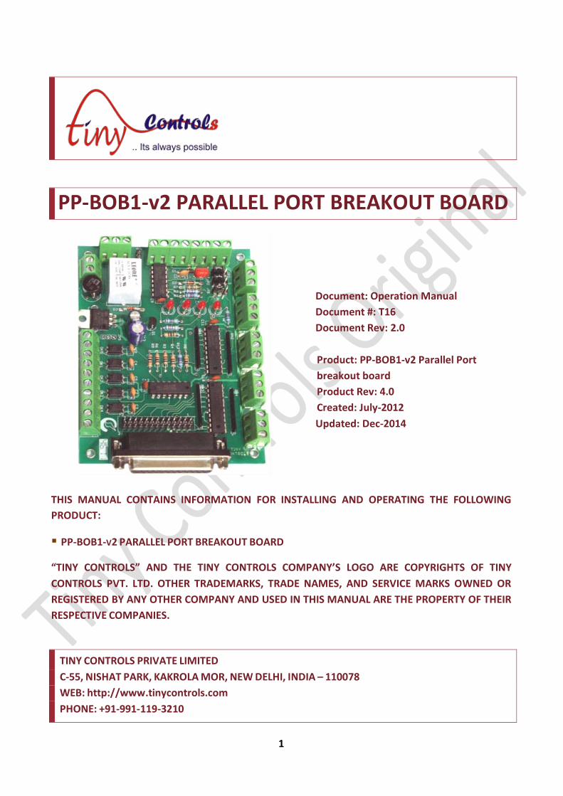
1 PP-BOB1-v2 PARALLEL PORT BREAKOUT BOARD Document: Operation Manual Document #: T16 Document Rev: 2.0 Product: PP-BOB1-v2 Parallel Port breakout board Product Rev: 4.0 Created: July-2012 Updated: Dec-2014 THIS MANUAL CONTAINS INFORMATION FOR INSTALLING AND OPERATING THE FOLLOWING PRODUCT: PP-BOB1-V2 PARALLEL PORT BREAKOUT BOARD “TINY CONTROLS” AND THE TINY CONTROLS COMPANY’S LOGO ARE COPYRIGHTS OF TINY CONTROLS PVT. LTD. OTHER TRADEMARKS, TRADE NAMES, AND SERVICE MARKS OWNED OR REGISTERED BY ANY OTHER COMPANY AND USED IN THIS MANUAL ARE THE PROPERTY OF THEIR RESPECTIVE COMPANIES. TINY CONTROLS PRIVATE LIMITED C-55, NISHAT PARK, KAKROLA MOR, NEW DELHI, INDIA – 110078 WEB: http://www.tinycontrols.com PHONE: +91-991-119-3210
Transcript of PP-BOB1-v2 PARALLEL PORT BREAKOUT BOARD · PP-BOB1-v2 PARALLEL PORT BREAKOUT BOARD ... used for any...
1
PP-BOB1-v2 PARALLEL PORT BREAKOUT BOARD
Document: Operation Manual
Document #: T16
Document Rev: 2.0
Product: PP-BOB1-v2 Parallel Port
breakout board
Product Rev: 4.0
Created: July-2012
Updated: Dec-2014
THIS MANUAL CONTAINS INFORMATION FOR INSTALLING AND OPERATING THE FOLLOWING
PRODUCT:
PP-BOB1-V2 PARALLEL PORT BREAKOUT BOARD
“TINY CONTROLS” AND THE TINY CONTROLS COMPANY’S LOGO ARE COPYRIGHTS OF TINY
CONTROLS PVT. LTD. OTHER TRADEMARKS, TRADE NAMES, AND SERVICE MARKS OWNED OR
REGISTERED BY ANY OTHER COMPANY AND USED IN THIS MANUAL ARE THE PROPERTY OF THEIR
RESPECTIVE COMPANIES.
TINY CONTROLS PRIVATE LIMITED
C-55, NISHAT PARK, KAKROLA MOR, NEW DELHI, INDIA – 110078
WEB: http://www.tinycontrols.com
PHONE: +91-991-119-3210
CONTENTS
1. MECHANICAL INSTALLATION 3
2. GENERAL DESCRIPTION 4
3. SPECIFICATIONS 5
4. BREAKOUT BOARD TERMNALS 6
5. CONNECTING OUTPUTS 7
6. CONNECTING INPUTS 8
7. JUMPER SETTINGS 9
8. LED INDICATORS 10
9. EXAMPLES: INPUT/ OUTPUT CONNECTIONS 10
10. CONNECTION DIAGRAM 12
11. MACH3 CONFIGURATION EXAMPLE 13
In the following pages, PP-BOB1-V2 “Parallel Port Breakout Board” is termed as
Breakout Board or simply BOB.
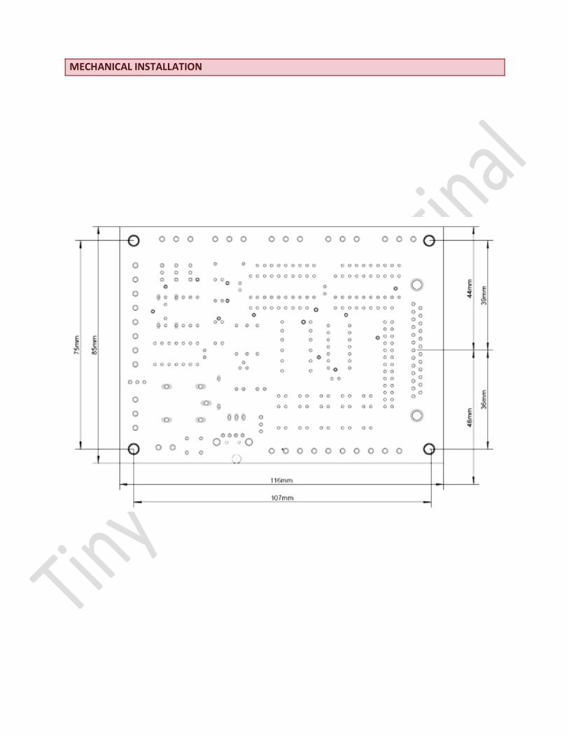
MECHANICAL INSTALLATION

GENERAL DESCRIPTION
The parallel port breakout board card is designed for a flexible interface between CNC
machine and computer system. The board is fully compatible with software like Mach3,
Turbo CNC, EMC2, KCAM etc.
The Breakout Board (BOB) translates signals between CNC machines and PC and
isolate PC motherboard from electrical problems. The BOB gives step and direction
outputs to steppers for 4 axes of CNC. The outputs for X- axis are buffered twice and
received from two different connectors to make card useful for gantry style machines
also. All the outputs are buffered and received through screw terminals from card.
A relay is provided on the board and an on-board 5V regulator drives a 5V output.
An on-board charge pump is provided for safety of card. This is jumper configurable and
it can be operated from frequencies as low as 200Hz to more than 15 KHz. Charge
pump can be set disabled and this buffered output can be used as general purpose
output.
Input terminals are compatible to 5-24V are given on the board. These are filtered for
noise immunity ensuring that there is no possibility of error.
LED indicators for relay, power, emergency input and CPGD make the signal debugging
task easy.
All the outputs can also be used as general purpose outputs making the system flexible.
A DB-25 connector and 26 pins pin-header is provided on the board making its
connections with PC easy.
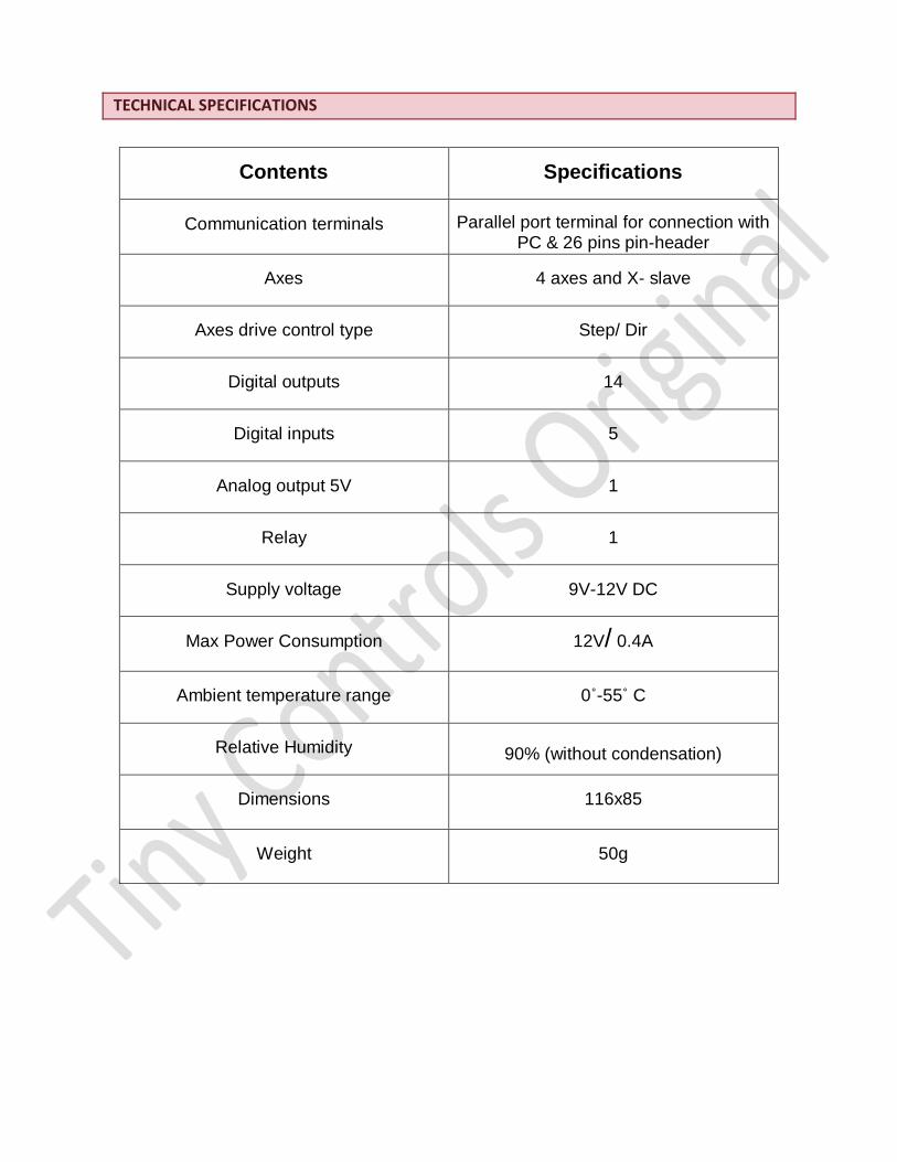
TECHNICAL SPECIFICATIONS
Contents
Specifications
Communication terminals
Parallel port terminal for connection with PC & 26 pins pin-header
Axes
4 axes and X- slave
Axes drive control type
Step/ Dir
Digital outputs
14
Digital inputs
5
Analog output 5V
1
Relay
1
Supply voltage
9V-12V DC
Max Power Consumption
12V/ 0.4A
Ambient temperature range
0˚-55˚ C
Relative Humidity
90% (without condensation)
Dimensions
116x85
Weight
50g
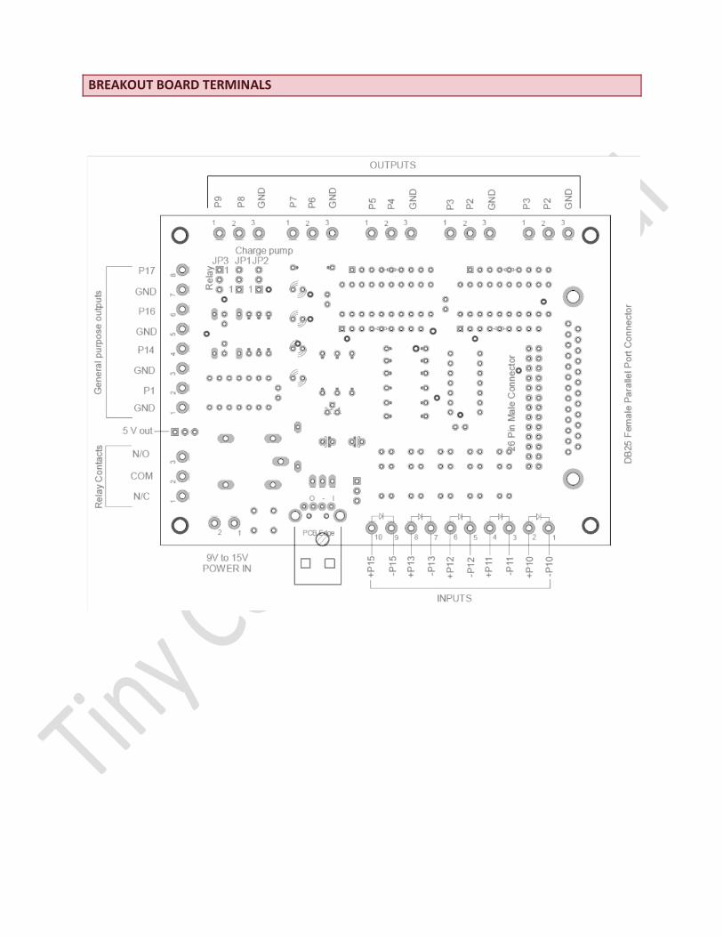
BREAKOUT BOARD TERMINALS
CONNECTING OUTPUTS:
AXES OUTPUTS:
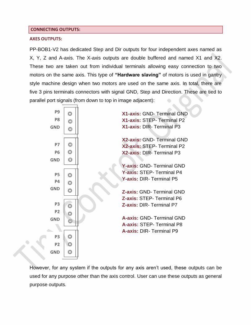
PP-BOB1-V2 has dedicated Step and Dir outputs for four independent axes named as
X, Y, Z and A-axis. The X-axis outputs are double buffered and named X1 and X2.
These two are taken out from individual terminals allowing easy connection to two
motors on the same axis. This type of “Hardware slaving” of motors is used in gantry
style machine design when two motors are used on the same axis. In total, there are
five 3 pins terminals connectors with signal GND, Step and Direction. These are tied to
parallel port signals (from down to top in image adjacent):
X1-axis: GND- Terminal GND
X1-axis: STEP- Terminal P2
X1-axis: DIR- Terminal P3
X2-axis: GND- Terminal GND
X2-axis: STEP- Terminal P2
X2-axis: DIR- Terminal P3
Y-axis: GND- Terminal GND
Y-axis: STEP- Terminal P4
Y-axis: DIR- Terminal P5
Z-axis: GND- Terminal GND
Z-axis: STEP- Terminal P6
Z-axis: DIR- Terminal P7
A-axis: GND- Terminal GND
A-axis: STEP- Terminal P8
A-axis: DIR- Terminal P9
However, for any system if the outputs for any axis aren’t used, these outputs can be
used for any purpose other than the axis control. User can use these outputs as general
purpose outputs.
P9
P8
GND
P7
P6
GND
P5
P4
GND
P3
P2
GND
P3
P2
GND

ANALOG OUTPUT 5V:
A 5V analog output signal is also provided on the control board. It is a regulator output
and remains active until the power supply continues to be supplied to the board.
RELAY:
Relay Contact terminals are attached directly from this
3 pin connector. Pins are marked as N/O; COM and
N/C. Digital Output signal P17 controls the relay or it
can also be used as a general purpose output and it
depends on mounting of jumper J3. This is discussed
in detail in Jumper settings section of the manual.
P14 and P16:
These outputs are general purpose outputs.
CONNECTING INPUTS:
POWER SUPPLY:
Connect a power supply of 9V-12V DC at the input pin of parallel port breakout board
for its operation.
The board ha s five opto-isolated inputs connected to signal P10, P11, P12, P13 and
P15. All inputs are filtered for noise immunity and are active low. Active low means
when the input of opto-isolator is driven, the signal becomes low.
Signal P15 is dedicated to emergency switch and the corresponding LED indicator
“ESTOP” shows the activity of this signal. The LED glows when the input is driven to
terminal.
The inputs are directly connected to the opto-couplers with 470 ohm series resistors.
Care must be taken to use appropriate resistor while connecting the signals above +5V
to the board so as to avoid any damage to the board. For 5V, no additional resistor is to
be added for input signal. See the connection diagram for more details. For more than
+5V, appropriate series resistors should be added.
The example circuits mentioned further in the manual show how to wire different types
of signals/ devices to board inputs.
JUMPER SETTINGS:
JUMPER 1 (JP1) AND JUMPER 2 (JP2):
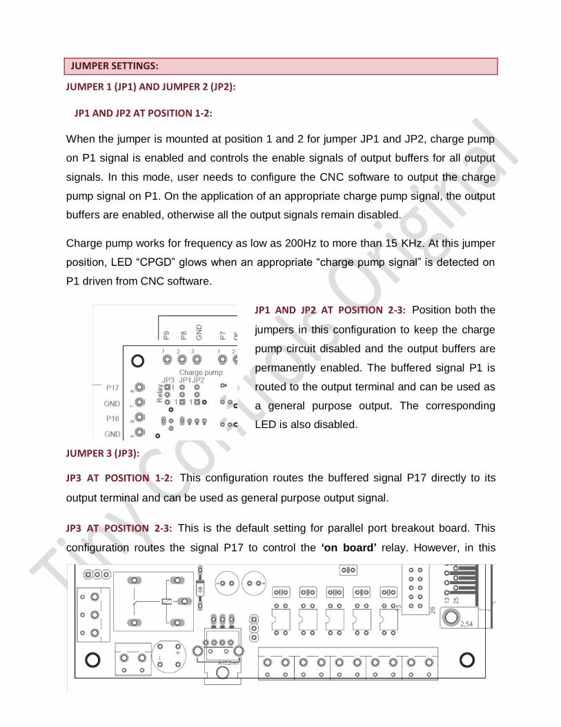
JP1 AND JP2 AT POSITION 1-2:
When the jumper is mounted at position 1 and 2 for jumper JP1 and JP2, charge pump
on P1 signal is enabled and controls the enable signals of output buffers for all output
signals. In this mode, user needs to configure the CNC software to output the charge
pump signal on P1. On the application of an appropriate charge pump signal, the output
buffers are enabled, otherwise all the output signals remain disabled.
Charge pump works for frequency as low as 200Hz to more than 15 KHz. At this jumper
position, LED “CPGD” glows when an appropriate “charge pump signal” is detected on
P1 driven from CNC software.
JP1 AND JP2 AT POSITION 2-3: Position both the
jumpers in this configuration to keep the charge
pump circuit disabled and the output buffers are
permanently enabled. The buffered signal P1 is
routed to the output terminal and can be used as
a general purpose output. The corresponding
LED is also disabled.
JUMPER 3 (JP3):
JP3 AT POSITION 1-2: This configuration routes the buffered signal P17 directly to its
output terminal and can be used as general purpose output signal.
JP3 AT POSITION 2-3: This is the default setting for parallel port breakout board. This
configuration routes the signal P17 to control the ‘on board’ relay. However, in this
1
1
position, output signal on terminal P17 isn’t available.
Signal P17 have an associated LED to indicate the activity, the LED works irrespective
of jumper position.
LED INDICATORS:
POWER: This LED glows when power is supplied to the card.
CPGD: This LED glows when a valid charge pump signal is detected.
RELAY: This LED glows when relay is activated.
ESTOP: This LED glows when an input signal is driven to emergency input terminal, P15.
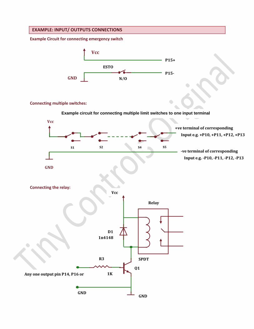
EXAMPLE: INPUT/ OUTPUTS CONNECTIONS
Example Circuit for connecting emergency switch
Connecting multiple switches:
Connecting the relay:
P15+
P15-
Vcc
GND N/O
ESTO
P
D1
1n4148
R3
1K
GND GND
Vcc
Relay
SPDT
Q1
2N3904/2N2222/BC547 Any one output pin P14, P16 or
P17
GND
Vcc
S1
+ve terminal of corresponding
Example circuit for connecting multiple limit switches to one input terminal
S2 S4 S5
Input e.g. +P10, +P11, +P12, +P13
-ve terminal of corresponding
Input e.g. -P10, -P11, -P12, -P13
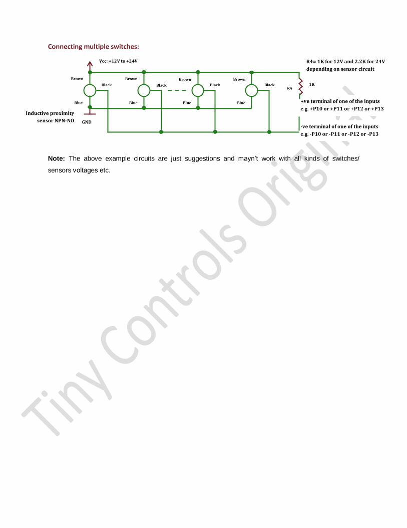
Connecting multiple switches:
Note: The above example circuits are just suggestions and mayn’t work with all kinds of switches/
sensors voltages etc.
GND
Black
Brown
Blue
Vcc: +12V to +24V
Black Black Black
Brown Brown Brown
Blue Blue Blue
Inductive proximity
sensor NPN-NO
R4
R4= 1K for 12V and 2.2K for 24V
depending on sensor circuit
1K
+ve terminal of one of the inputs
e.g. +P10 or +P11 or +P12 or +P13
-ve terminal of one of the inputs
e.g. -P10 or -P11 or -P12 or -P13
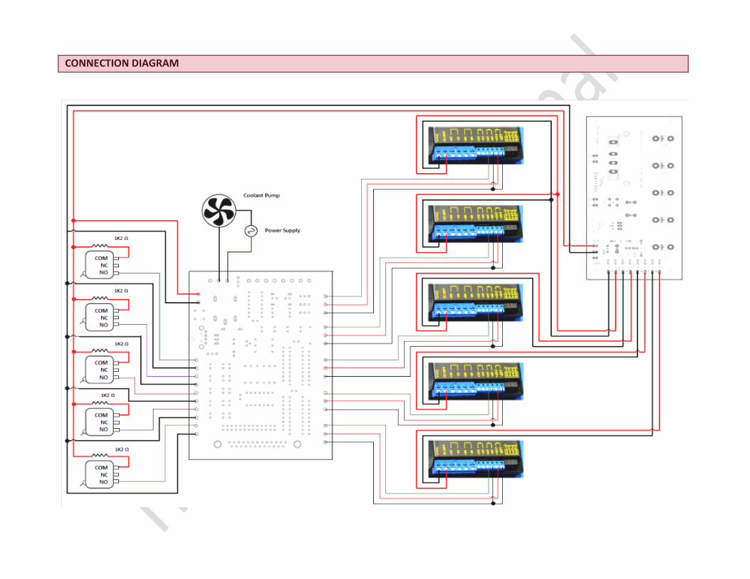
CONNECTION DIAGRAM
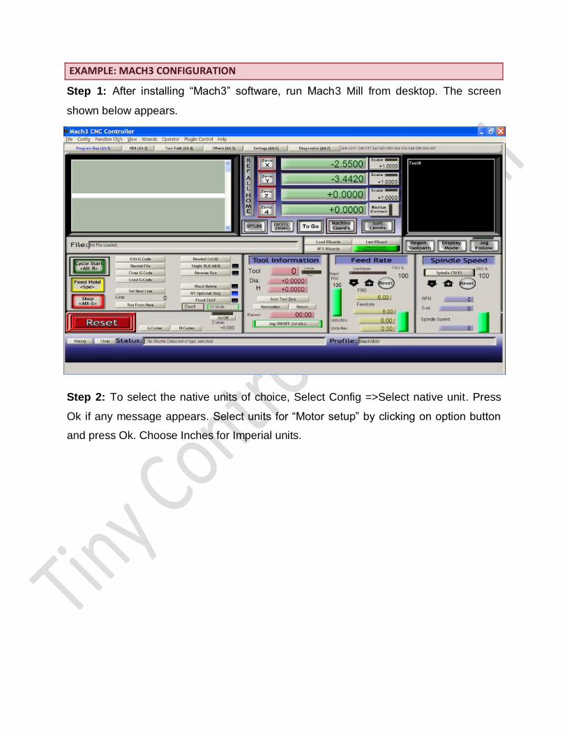
EXAMPLE: MACH3 CONFIGURATION
Step 1: After installing “Mach3” software, run Mach3 Mill from desktop. The screen
shown below appears.
Step 2: To select the native units of choice, Select Config =>Select native unit. Press
Ok if any message appears. Select units for “Motor setup” by clicking on option button
and press Ok. Choose Inches for Imperial units.
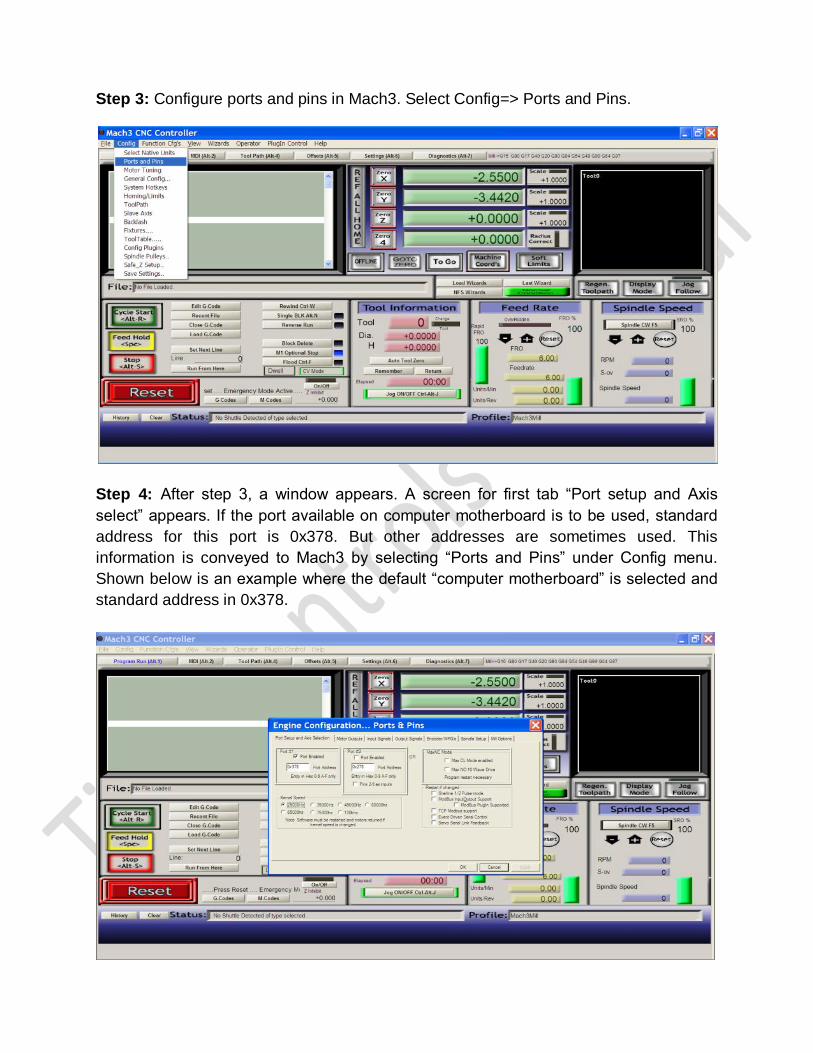
Step 3: Configure ports and pins in Mach3. Select Config=> Ports and Pins.
Step 4: After step 3, a window appears. A screen for first tab “Port setup and Axis
select” appears. If the port available on computer motherboard is to be used, standard
address for this port is 0x378. But other addresses are sometimes used. This
information is conveyed to Mach3 by selecting “Ports and Pins” under Config menu.
Shown below is an example where the default “computer motherboard” is selected and
standard address in 0x378.
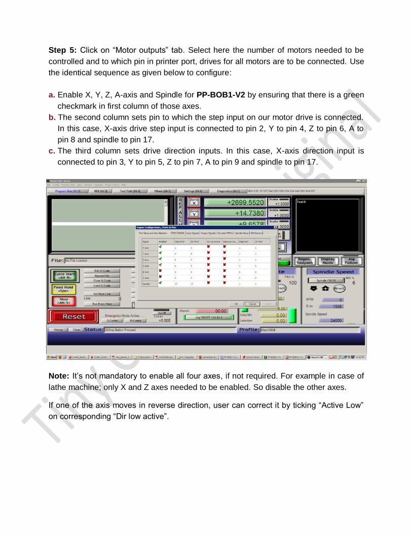
Step 5: Click on “Motor outputs” tab. Select here the number of motors needed to be
controlled and to which pin in printer port, drives for all motors are to be connected. Use
the identical sequence as given below to configure:
a. Enable X, Y, Z, A-axis and Spindle for PP-BOB1-V2 by ensuring that there is a green
checkmark in first column of those axes.
b. The second column sets pin to which the step input on our motor drive is connected.
In this case, X-axis drive step input is connected to pin 2, Y to pin 4, Z to pin 6, A to
pin 8 and spindle to pin 17.
c. The third column sets drive direction inputs. In this case, X-axis direction input is
connected to pin 3, Y to pin 5, Z to pin 7, A to pin 9 and spindle to pin 17.
Note: It’s not mandatory to enable all four axes, if not required. For example in case of
lathe machine; only X and Z axes needed to be enabled. So disable the other axes.
If one of the axis moves in reverse direction, user can correct it by ticking “Active Low”
on corresponding “Dir low active”.
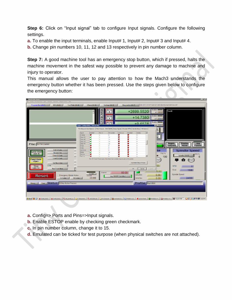
Step 6: Click on “Input signal” tab to configure Input signals. Configure the following
settings.
a. To enable the input terminals, enable Input# 1, Input# 2, Input# 3 and Input# 4.
b. Change pin numbers 10, 11, 12 and 13 respectively in pin number column.
Step 7: A good machine tool has an emergency stop button, which if pressed, halts the
machine movement in the safest way possible to prevent any damage to machine and
injury to operator.
This manual allows the user to pay attention to how the Mach3 understands the
emergency button whether it has been pressed. Use the steps given below to configure
the emergency button:
a. Config=> Ports and Pins=>Input signals.
b. Enable ESTOP enable by checking green checkmark.
c. In pin number column, change it to 15.
d. Emulated can be ticked for test purpose (when physical switches are not attached).
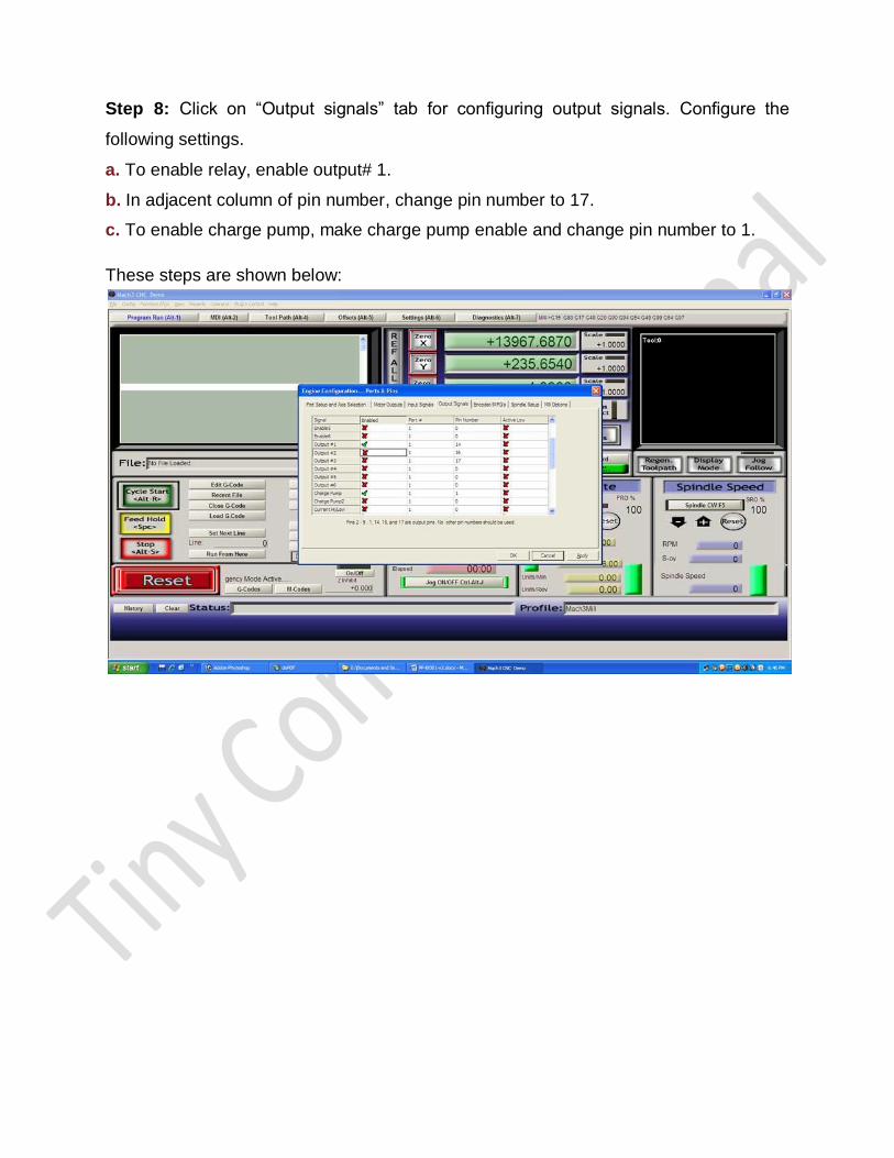
Step 8: Click on “Output signals” tab for configuring output signals. Configure the
following settings.
a. To enable relay, enable output# 1.
b. In adjacent column of pin number, change pin number to 17.
c. To enable charge pump, make charge pump enable and change pin number to 1.
These steps are shown below:
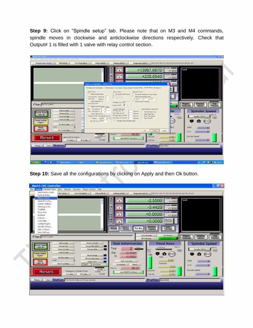
Step 9: Click on “Spindle setup” tab. Please note that on M3 and M4 commands,
spindle moves in clockwise and anticlockwise directions respectively. Check that
Output# 1 is filled with 1 valve with relay control section.
Step 10: Save all the configurations by clicking on Apply and then Ok button.
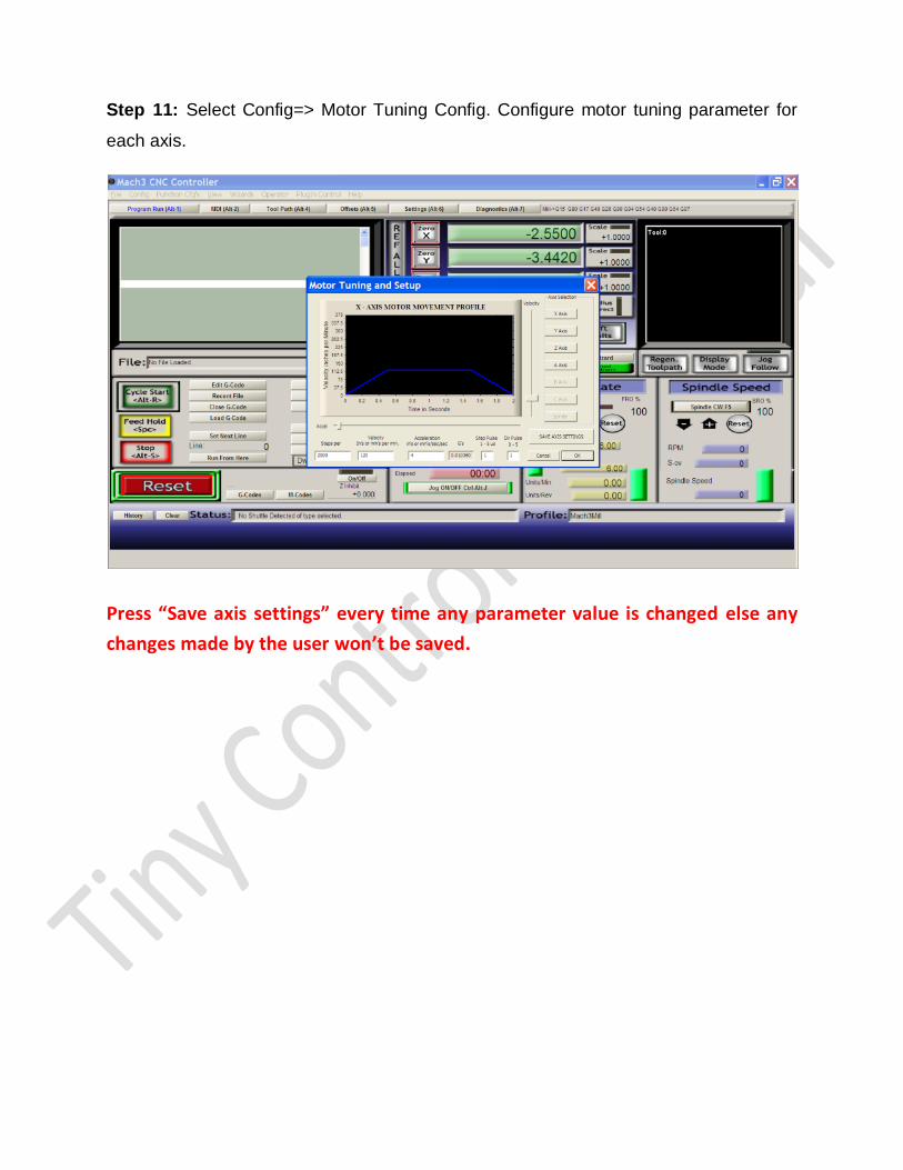
Step 11: Select Config=> Motor Tuning Config. Configure motor tuning parameter for
each axis.
Press “Save axis settings” every time any parameter value is changed else any
changes made by the user won’t be saved.