
Porting Linux to a Hypervisor Based Embedded...
45
IT 13 047 Examensarbete 30 hp Juni 2013 Porting Linux to a Hypervisor Based Embedded System G Hariprasad Institutionen för informationsteknologi Department of Information Technology
Transcript of Porting Linux to a Hypervisor Based Embedded...
IT 13 047
Examensarbete 30 hpJuni 2013
Porting Linux to a Hypervisor Based Embedded System
G Hariprasad
Institutionen för informationsteknologiDepartment of Information Technology

Teknisk- naturvetenskaplig fakultet UTH-enheten Besöksadress: Ångströmlaboratoriet Lägerhyddsvägen 1 Hus 4, Plan 0 Postadress: Box 536 751 21 Uppsala Telefon: 018 – 471 30 03 Telefax: 018 – 471 30 00 Hemsida: http://www.teknat.uu.se/student
Abstract
Porting Linux to a Hypervisor Based EmbeddedSystem
G Hariprasad
Virtualization is used to improve overall system security, isolate the hardware and it properly manages the available system resources also. The main purpose of using virtualization in embedded systems is to increase the system security by isolating the underlying hardware and also by providing multiple secure execution environments for the guests. A hypervisor also called as the Virtual Machine monitor is responsible for mapping virtual resources to physical resources. Hypervisor based virtualization is gaining more popularity in embedded systems because of the security focussed mission critical applications. Linux OS is chosen because of its popular use in embedded systems. In this thesis, we list out the modifications required to port a Linux kernel onto a hypervisor. This Linux Kernel is already ported to ARM CPU and the hypervisor in question has been developed by Swedish Institute of Computer Science (SICS).
Tryckt av: Reprocentralen ITCIT 13 047Examinator: Philipp RümmerÄmnesgranskare: Arnold PearsHandledare: Oliver Schwarz

Acknowledgments
My sincere thanks to Christian Gehrmann for giving me an opportunity to carryout my thesis work at SICS. I would like to thank Oliver Schwarz, my supervi-sor for guiding me during the course of my thesis work. Viktor Do and ArashVahidi for helping me out with all the technical questions and details.
My heartiest thanks to Nikos Nikoleris and Dr. Philipp Rummer for their sup-port, guidance and patience in reviewing my thesis. Without them this wouldnot have been possible.
I also want to thank my friends and family for their love and support.

Contents
1 Introduction 121.1 Operating Systems . . . . . . . . . . . . . . . . . . . . . . . . . . 121.2 Embedded Systems . . . . . . . . . . . . . . . . . . . . . . . . . . 121.3 Virtualization and Embedded Systems . . . . . . . . . . . . . . . 131.4 Hypervisors . . . . . . . . . . . . . . . . . . . . . . . . . . . . . . 14
1.4.1 The SICS Hypervisor . . . . . . . . . . . . . . . . . . . . 151.5 Problem Definition . . . . . . . . . . . . . . . . . . . . . . . . . . 151.6 Thesis Organization . . . . . . . . . . . . . . . . . . . . . . . . . 16
2 Background 172.1 Kernels . . . . . . . . . . . . . . . . . . . . . . . . . . . . . . . . 172.2 Linux Kernel . . . . . . . . . . . . . . . . . . . . . . . . . . . . . 17
2.2.1 Linux System Call . . . . . . . . . . . . . . . . . . . . . . 182.2.2 Linux Interrupt Handling . . . . . . . . . . . . . . . . . . 182.2.3 Linux Memory Management . . . . . . . . . . . . . . . . . 18
2.3 Virtualization and Virtual Machines . . . . . . . . . . . . . . . . 192.3.1 Binary Translation . . . . . . . . . . . . . . . . . . . . . . 192.3.2 Para-Virtualization . . . . . . . . . . . . . . . . . . . . . . 192.3.3 Hardware Virtualization . . . . . . . . . . . . . . . . . . . 19
2.4 ARM Architecture . . . . . . . . . . . . . . . . . . . . . . . . . . 202.4.1 ARM Introduction . . . . . . . . . . . . . . . . . . . . . . 202.4.2 ARM Processor modes . . . . . . . . . . . . . . . . . . . . 202.4.3 ARM Registers . . . . . . . . . . . . . . . . . . . . . . . . 212.4.4 CPSR . . . . . . . . . . . . . . . . . . . . . . . . . . . . . 212.4.5 Interrupt Handling in ARM . . . . . . . . . . . . . . . . . 212.4.6 ARM Coprocessor . . . . . . . . . . . . . . . . . . . . . . 222.4.7 MMU . . . . . . . . . . . . . . . . . . . . . . . . . . . . . 232.4.8 Page Tables . . . . . . . . . . . . . . . . . . . . . . . . . . 232.4.9 TLB . . . . . . . . . . . . . . . . . . . . . . . . . . . . . . 23
3 Related Work 13.1 Hypervisors . . . . . . . . . . . . . . . . . . . . . . . . . . . . . . 1
3.1.1 Xen Hypervisor . . . . . . . . . . . . . . . . . . . . . . . . 13.2 Related porting work done . . . . . . . . . . . . . . . . . . . . . . 3
3.2.1 OpenBSD is ported on Fiasco . . . . . . . . . . . . . . . . 33.3 freeRTOS porting to ARM based Hypervisor . . . . . . . . . . . 4
3.3.1 Interposition . . . . . . . . . . . . . . . . . . . . . . . . . 43.3.2 Memory Protection . . . . . . . . . . . . . . . . . . . . . . 4
4
4 OVP Installation and Setup 64.1 Introduction to OVP . . . . . . . . . . . . . . . . . . . . . . . . . 64.2 OVP Tools . . . . . . . . . . . . . . . . . . . . . . . . . . . . . . 6
4.2.1 ARM Integrator/CP . . . . . . . . . . . . . . . . . . . . . 64.2.2 Sourcery G++ Lite for ARM EABI . . . . . . . . . . . . 7
4.3 Server-Client Setup . . . . . . . . . . . . . . . . . . . . . . . . . . 7
5 Kernel Modifications 85.1 SICS Hypervisor . . . . . . . . . . . . . . . . . . . . . . . . . . . 8
5.1.1 The Hypervisor . . . . . . . . . . . . . . . . . . . . . . . . 85.1.2 Hypervisor Modes . . . . . . . . . . . . . . . . . . . . . . 85.1.3 Hypercall Interface . . . . . . . . . . . . . . . . . . . . . . 95.1.4 DMA Virtualization . . . . . . . . . . . . . . . . . . . . . 10
5.2 Linux Kernel . . . . . . . . . . . . . . . . . . . . . . . . . . . . . 105.3 IVT and modification . . . . . . . . . . . . . . . . . . . . . . . . 11
5.3.1 Program flow . . . . . . . . . . . . . . . . . . . . . . . . . 125.4 Page Tables . . . . . . . . . . . . . . . . . . . . . . . . . . . . . . 13
6 Conclusion and Future Work 156.1 Conclusion . . . . . . . . . . . . . . . . . . . . . . . . . . . . . . 156.2 Future Work . . . . . . . . . . . . . . . . . . . . . . . . . . . . . 15
5
List of Figures
1.1 Use case for Virtualization in Embedded systems . . . . . . . . . 131.2 Standard security use case . . . . . . . . . . . . . . . . . . . . . . 141.3 General Hypervisor . . . . . . . . . . . . . . . . . . . . . . . . . . 141.4 SICS Hypervisor . . . . . . . . . . . . . . . . . . . . . . . . . . . 15
2.1 CPSR . . . . . . . . . . . . . . . . . . . . . . . . . . . . . . . . . 21
3.1 Xen Architecture . . . . . . . . . . . . . . . . . . . . . . . . . . . 2
5.1 IVT Modification . . . . . . . . . . . . . . . . . . . . . . . . . . . 12
6
List of Tables
2.1 Vector Table . . . . . . . . . . . . . . . . . . . . . . . . . . . . . 222.2 ARM Page tables . . . . . . . . . . . . . . . . . . . . . . . . . . . 23
5.1 Hypercall Interface . . . . . . . . . . . . . . . . . . . . . . . . . . 10
7

ABI Application Binary Interface
API Application Programming Interface
CPSR Current Program Status Register
CPU Central Processing Unit
DMA Direct Memory Access
DMAC Direct Memory Access Controller
DMR Dual Modular redundancy
DRM Digital Rights Management
EPT Extended Page Table
FCSE PID Fast Context-Switch Extension Process ID
I/O Input/Output
IOMMU I/O Memory Management Unit
IPC interprocess communication
ISA Instruction Set Architecture
MAC Mandatory Access Control
MMM Mixed-Mode Multicore reliability
MMU Memory management Unit
MPU Memory Protection Unit
MVA Modified Virtual Address
NUMA Non-Uniform Memory Architecture
OMTP Open Mobile Terminal Platform
OSTI Open and Secure Terminal Initiative
OVP Open Virtual Platforms
SPMD Single Program Multiple Data
SPSR Saved Program Status Register
9
TCB Trusted Computing Base
TCB Task Control Block
TCG Trusted Computing Group
TLB Translation Lookaside Buffer
TPM Trusted platform Module
TPR Task Priority Register
VBAR Vector Base Address Register
VM Virtual Machine
VMCB Virtual Machine Control Block
VMCS Virtual Machine Control Structure
VMI VM Introspection
VMM VM Monitor
VPID Virtual Process Identifier
10

Chapter 1
Introduction
Security has always been an essential feature of embedded systems and therapid increase in growth, design requirements and performance of the embed-ded systems has made security a challenging feature of the modern systems.The demand for a secure system is natural. Even though by creating an inde-pendent execution environment in the hardware where the trusted applicationis safe, this method is expensive.A way to create a secure system is through virtualization which uses hypervisorsto provide an abstraction layer separating virtual machines from the CPU andisolating the virtual machines from one another. Also, in a complex multi-corehardware abstraction layer provided can manage the system more easily.
In this thesis, we describe the modifications needed to port a complex oper-ating system like Linux onto a hypervisor and the challenges faced.
1.1 Operating Systems
General purpose computers typically have an operating system, a software whichacts as an interface between the user and the hardware. By providing an in-terface to the user, the operating systems makes the computer more convenientto use. It is designed to manage the system resources and the memory alloca-tion, controlling input and output devices [16]. With the development of lighterkernels, the use of operating systems in embedded systems has become common.
1.2 Embedded Systems
An embedded system can be defined as a computer which is designed for aspecific purpose. Since it is designed for a particular task, embedded systemcannot be used as general purpose computer. The firmware, which is the soft-ware required for an embedded system is typically stored on the chip whereasin a general purpose computer, the software is stored in the disk. Dependingon the task it is designed for, an embedded system can use real time operat-ing systems with smaller footprints. Designing embedded systems faces designconstraints like limited memory, low cost, low power consumption, reliability,and guaranteed real time behaviour [9]. The embedded systems are widely usedin industries like power generation, process control, manufacturing, defence,
12
telecommunication, automotive systems etc. An embedded system mainly con-sists of 2 parts:
1. The hardware which in turn consists of a micro-controller/microprocessoralong with memory, input/output peripherals, display and any other userinterface.
2. The software written to perform a dedicated task is written, compiled andflashed into the non volatile memory within the hardware.
1.3 Virtualization and Embedded Systems
A few decades back, when the concept of embedded systems was introduced,it basically meant systems which are simple, single purpose and came with lotof design constraints. They offered relatively less complex software. But thepresent and future embedded systems like smartphones or mission critical sys-tems offer more functionality compared to their predecessors and the developersneeds to address a lot of issues. They are expected to run applications meantfor general purpose systems and designed accordingly.By introducing virtualization in embedded systems, the system developer canaddress certain key issues:
1. Since embedded systems tend to become more open, the developers needto isolate the proprietary software and open source software [10]. Theembedded hypervisor provides isolation between the open source softwareand proprietary software to coexist in the same system.
2. By running the operating system in a virtual machine, access to the rest ofthe system is minimal thereby increasing the security in an open system.
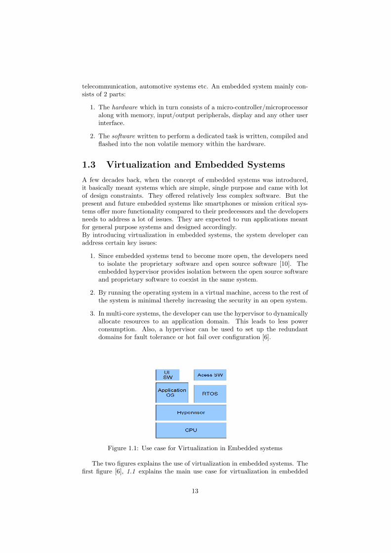
3. In multi-core systems, the developer can use the hypervisor to dynamicallyallocate resources to an application domain. This leads to less powerconsumption. Also, a hypervisor can be used to set up the redundantdomains for fault tolerance or hot fail over configuration [6].
Figure 1.1: Use case for Virtualization in Embedded systems
The two figures explains the use of virtualization in embedded systems. Thefirst figure [6], 1.1 explains the main use case for virtualization in embedded
13
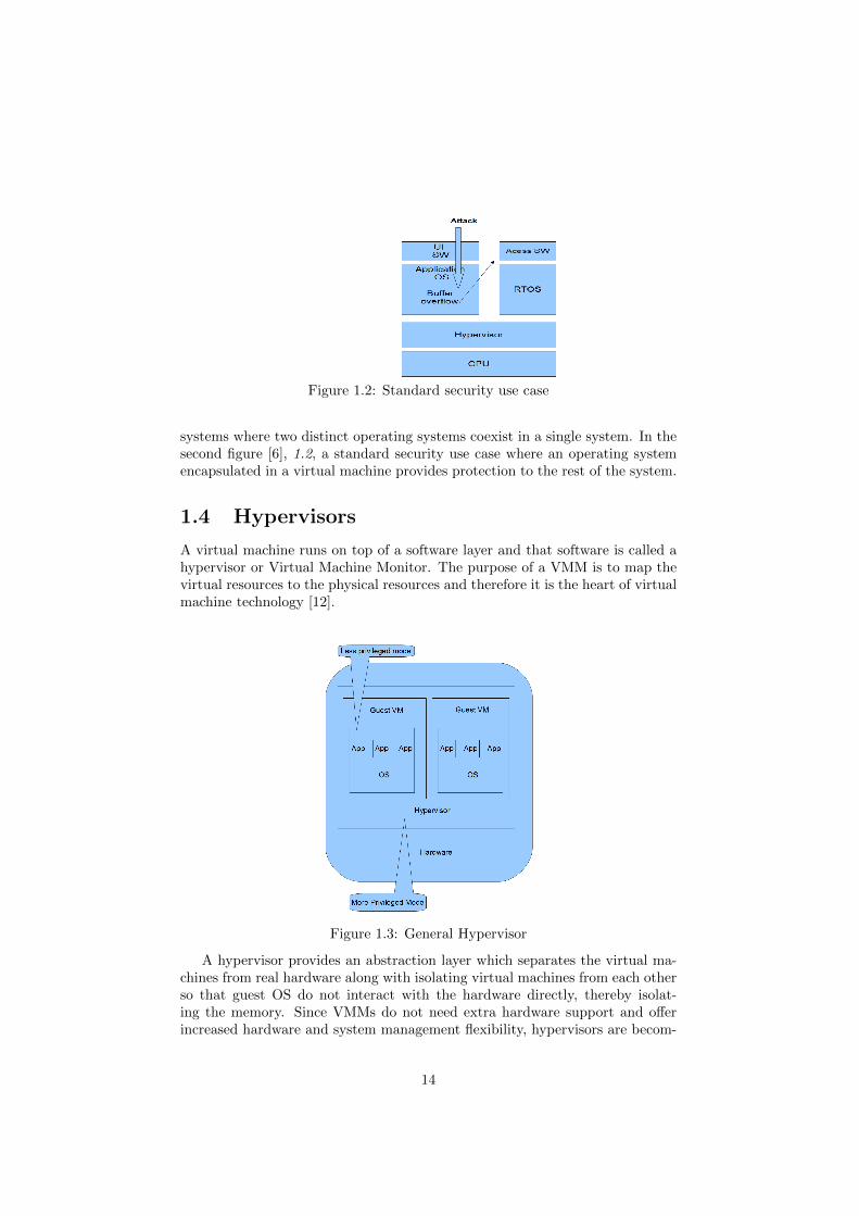
Figure 1.2: Standard security use case
systems where two distinct operating systems coexist in a single system. In thesecond figure [6], 1.2, a standard security use case where an operating systemencapsulated in a virtual machine provides protection to the rest of the system.
1.4 Hypervisors
A virtual machine runs on top of a software layer and that software is called ahypervisor or Virtual Machine Monitor. The purpose of a VMM is to map thevirtual resources to the physical resources and therefore it is the heart of virtualmachine technology [12].
Figure 1.3: General Hypervisor
A hypervisor provides an abstraction layer which separates the virtual ma-chines from real hardware along with isolating virtual machines from each otherso that guest OS do not interact with the hardware directly, thereby isolat-ing the memory. Since VMMs do not need extra hardware support and offerincreased hardware and system management flexibility, hypervisors are becom-
14
ing more popular. Xen and VMWare ESX are examples of popular hypervisors.Both hypervisors achieve complete virtualization of the system through differentmeans, Xen uses paravirtualization and VMWare ESX uses binary translation.
Hypercalls are functions which are used by modified guest operating systems tocommunicate with the hypervsior [11]. When a hypercall is issued, the systemcontrol is transferred to a more privileged state and highly privileged operationslike updating page tables can take place. The hypercall in a hypervisor is similarto system call in an operating system.
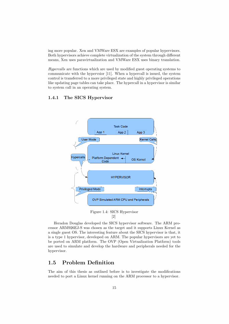
1.4.1 The SICS Hypervisor
Figure 1.4: SICS Hypervisor[2]
Heradon Douglas developed the SICS hypervisor software. The ARM pro-cessor ARM926EJ-S was chosen as the target and it supports Linux Kernel asa single guest OS. The interesting feature about the SICS hypervisor is that, itis a type 1 hypervisor, developed on ARM. The popular hypervisors are yet tobe ported on ARM platform. The OVP (Open Virtualization Platform) toolsare used to simulate and develop the hardware and peripherals needed for thehypervisor.
1.5 Problem Definition
The aim of this thesis as outlined before is to investigate the modificationsneeded to port a Linux kernel running on the ARM processor to a hypervisor.
15
1.6 Thesis Organization
The thesis is organized into 6 chapters. The first chapter is about Introduction,which will have general information about the operating systems, embeddedsystems, virtualization and embedded systems, hypervisors and the SICS hy-pervisor. The 2nd chapter Background has information about kernels, Linuxkernel, types of virtualization, and a brief description about the ARM archi-tecture. In chapter 3, Related Work we describe the Xen hypervisor and thepara-virtualization using Xen. Also, the OpenBSD porting on Fiasco and freeR-TOS porting on the SICS hypervsior are discussed. The differences between thenormal freeRTOS kernel and the changes made to it so that it can be ported toa hypervisor are also included.
Chapter 4 OVP Installtion and Setup describes the tools needed to modify,re-compile and simulate the system. In chapter5 Kernel Modifications we dis-cuss the porting of the Linux kernel. It includes the identification of the Linuxkernel to be modified and two major modifications needed to port the identifiedLinux kernel on to the hypervisor are explained. The last chapter6, Conclusionand Future Work has the conclusion of the thesis and possible future work re-lated to this is discussed. The literature work done by others related to thisthesis is also included.
16
Chapter 2
Background
This background chapter has all the needed information about kernels, generalLinux kernel, system calls in Linux, handling interrupts in Linux and managingmemory in Linux. Also, ARM architecture and its features are explained.
2.1 Kernels
A kernel is the main component of an operating system, immediately above thehardware architecture level and generally considered as the lowest level of soft-ware. The most basic operations performed by an operating system is resourcemanagement and resource sharing are taken care of by the kernel [8]. Also, thekernel provides the abstractions for the processes running in the user mode. Thisabstraction is necessary since the processes running in the user mode requireaccess to the hardware resource but cannot access them directly. To achieveprotection between the processes, we can divide the OS into two parts [19], thekernel space and the user space.
There are two types of kernel architectures available. One is the monolithickernel and the second one is the micro-kernel. A monolithic kernel architecturehas all the code to get executed in the kernel space. All the needed devicedrivers, protocols, IPC modules are included in that kernel. In a micro-kernel,only the code needed to run an operating system gets executed in the kernelspace. The device drivers, file systems, protocol stacks run in user space. Bothmonolithic kernels and micro kernels have their own advantages and disadvan-tages. When the monolithic kernel crashes, then the entire system crashes. Also,monolithic kernel has a typically larger memory footprint when compared witha micro kernel. On the other hand, performance has been a major challenge formicro-kernels.
2.2 Linux Kernel
Developed by Linus Torvalds, the Linux kernel is a member of family of Unixlike operating systems. Linux is an open source operating system and its sourcecode is available under the GNU General Public License (GPL).
17
2.2.1 Linux System Call
A system call can be defined as a request sent by the programs to the operatingsystem to access services that are strictly controlled by the kernel. Some exam-ples of popular system calls are open, read, write, close, exit, fork, kill,
wait etc. There are around 300 system calls in the Linux operating system.The following steps describes how to create and add Linux system calls in theLinux OS.
1. The system call table is found in the file /arch/arm/kernel/calls.S.The programmer adds his own system call at the end of the file in thefollowing format .long SYS_CALL_NAME
2. Then the system call is declared in the file unistd.h present in thefolder /arch/arm/include/asm/unistd.h. Increment the existing sys-tem call number by 1. The new system call declaration looks like this#define __NR_SYS_CALL_NAME XXX
3. Define the system call function in C language and store the .c file in thefolder /usr/src/Linux-x.x.x/Kernel
4. Declare the system call in the file /include/linux/syscalls.h so thatthe system call gets linked with the ASM table in the file calls.h Thelinkage is done through asmlinkage long CALL_NAME(parameters)
5. Now create a makefile in the folder where the system call is defined.The make file must contain the path to the system call definition filecore-y += /kernel /.../... /syscall.
6. Finally the object file of the system call definition is added to the makefile. obj-y := mysyscall.o
2.2.2 Linux Interrupt Handling
In the Linux operating system, interrupts are handled in a similar way to thesignals in the user space. In simple words, the device’s interrupt handler is reg-istered and are invoked when an interrupt is generated. If the software handleris not registered in the Linux kernel, then the interrupt is simply ignored. Aregistry is available in the Linux kernel which keeps the interrupt lines some-thing analogous to the I/O port registry. When an interrupt channel is neededby a module, the particular module requests an interrupt channel or IRQ andthe same module has to release it after finished using the interrupt channel.The library file <linux/interrupt.h> contains the necessary functions neededto implement interrupt registration [1].
2.2.3 Linux Memory Management
Like any other operating system, Linux also provides memory related serviceslike virtual memory, shared memory and protection to the applications run-ning on it. These services [5] are built on a programming foundation includ-ing a peripheral device called MMU. The purpose of a MMU is to trans-late the physical address into linear address and when a CPU tries to ac-cess the memory region illegally the MMU requests for a page fault interrupt.
18
Linux’s pte_*(), flush_tlb_*() and update_mmu_cache() functions are thekernel’s Memory Management Unit API. These functions connect Linux’s hardware-generic memory management service algorithms to the host processor’s MemoryManagement Unit hardware. They are sufficiently abstract, however, in thatthey depend completely on the MMU API. A thorough understanding of thisAPI is therefore essential to successful use of Linux in an embedded setting.
2.3 Virtualization and Virtual Machines
We can define virtualization as the creation of a virtual version of resources, likememory or operating systems or servers or network resources [21]. In this thesiswe deal with a certain type of virtualization called para-virtualization where onecan create many virtual systems inside a single physical system. System virtu-alization is achieved by running an additional layer called hypervisor, betweenthe hardware and the virtualized systems. This hypervisor manages in sharingof all hardware resources of the hardware between the guests. A virtual machinecan be defined as a software implementation of a computer which functions likea real physical machine.
Some privileged instructions have one result when executed in privileged modeand a different result when executed in non-privileged mode. Those instruc-tions are called privilege-sensitive instructions. An Instruction Set Architecture(ISA) can be called classically virtualizable provided if it does not contain theprivilege-sensitive instructions.
2.3.1 Binary Translation
The Intel x86 architecture has privilege-sensitive instructions making full vir-tualization impossible. So, to achieve virtualization in Intel x86 architecture,VMware employed Binary translation.
2.3.2 Para-Virtualization
A guest OS is modified and recompiled prior to installation inside a virtualmachine. The guest OS is modified in such a way that the instructions whichare non virtualizable are replaced by hypercalls. The hypercalls communicatedirectly with the virtualization layer hypervisor [24]. This virtualization tech-nology is called Para-Virtualization, and provides an interface to the virtualmachine that can differ slightly from that of the underlying hardware [20]. Oneimportant advantage of para-virtualization over binary translation is that it typ-ically has lower performance overhead. The guest operating systems run witha fully paravirtualized disk and network interfaces, timers, interrupts, access topage table[4].
2.3.3 Hardware Virtualization
In hardware virtualization, a hypervisor is used to abstract the physical hard-ware layer [7]. A good example is the AMD-V and Intel virtualization technology
19
processor where the hardware is custom made to support the external virtual-ization software. Virtualizing the hardware enables the use of more than oneoperating system on the same hardware [13].
2.4 ARM Architecture
2.4.1 ARM Introduction
As mentioned earlier, the hypervisor developed by SICS is implemented on topof the ARM926EJ-S CPU. The contemporary CPUs available in the market canbe classified as either RISC or CISC CPUs. Many 32-bit embedded systems arebuilt on an ARM CPU, which is a RISC (Reduced Instruction Set Computer).The important attributes exhibited by a RISC CPU are:
1. A large uniform register file.
2. Load/Store architecture, which implies that the operations executed op-erate only on the contents of the register and not on the memory contents.
3. Simple addressing mode.
4. For simplifying the instruction decode, uniform and fixed length instruc-tion fields are provided.
The instructions for CISC are more complex, variable in size and need moreexecution cycles. This is due to the fact that CISC machines are dependenton the hardware for the instruction functionality. The ability to achieve targetcode density and low power consumption has made the ARM processor to bepresent in almost all the embedded devices manufactured.
2.4.2 ARM Processor modes
There are 7 processor modes supported by the ARM CPU. They are:
1. User mode The normal execution mode for user programs
2. Fast Interrupt (FIQ) This mode supports high speed interrupts.
3. Interrupt request (IRQ) This mode handles the general interrupts
4. Supervisor mode The mode in which the OS operates normally and alsothe mode when the power is applied to the system
5. Abort mode The mode is needed for implementing virtual memory
6. Undefined Supports software emulation of hardware co-processors
7. System This mode runs the OS tasks
Other than the user mode all the other modes are privileged modes. The dif-ference between a privileged mode and non privileged mode is that a privilegedmode has both read and write control over the CPSR whereas a non privilegedmode has only read control over the CPSR.
20
2.4.3 ARM Registers
There are 31 registers available on an ARM core where only 16 registers (r0-r15)are visible at a particular point of time. Among the 16 registers available, thelast 3 registers, r13-r15 are assigned with special functions.
Stack Pointer : The register r13 is used as the stack pointer, where thehead of the stack is stored in current processor mode.
Link Register : The register r14 is used as the Link register. Whenever asubroutine is called the CPU stores the return address in LR.
Program Counter: The register r15 is used as the Program Counter. Theaddress of the next instruction to be fetched is stored here.
2.4.4 CPSR
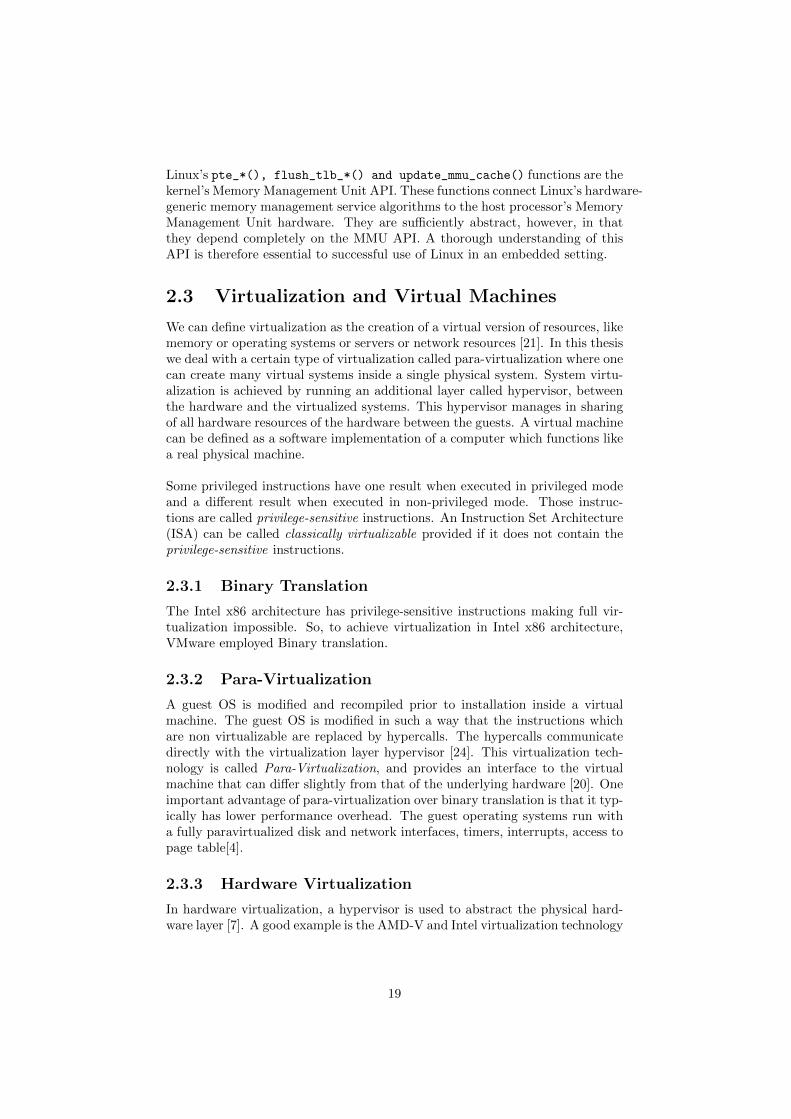
The current program status register is a 32-bit register apart from the 16 generalpurpose registers, which is used to monitor and control the internal operationsof the ARM CPU. As seen in the figure below [17], the CPSR has 4 sub-fieldseach 8 bits wide.
The first 8 bits represent the control field and contain the details about theprocessor modes, thumb state and the interrupt masks. The next 16 bits rep-resent an extension and status fields and they are reserved for future use. Thelast 8 bits are the flag fields where the last 4 bits represent the conditional flagswhere the results of the arithmetic operations are stored.
Figure 2.1: CPSR
2.4.5 Interrupt Handling in ARM
In this section we will discuss the exception handling mechanism in the ARMprocessor. Whenever the system is interrupted, the CPU suspends temporarilythe execution and starts executing the interrupt service routine (ISR). This ISRis stored in the exception vector table which in turn is saved at a specific memory
21
address. The entries in the vector table usually contain a branch instructionwhich points to the start of a routine.
1. Reset Vector: This contains the location of the instruction executed firstwhen power is applied to the processor. This will branch into theinitialization code.
2. Undefined Instruction Vector: If the processor cannot decode aninstruction then this vector table entry is used.
3. Software Interrupt Vector: Whenever there is a software interrupt,this vector table entry is used.
4. Prefetch Abort Vector: If the CPU violates the access rights by tryingto access an instruction from an address by violating the access rights thenthis vector table entry is used.
5. Data Abort Vector: If an instruction attempts to access the data mem-ory without the right access permissions, data abort vector is used.
6. Interrupt request Vector: If an external hardware interrupts the CPUthen this vector is used. It also requires the unmasking of IRQs in theCPSR
7. Fast Interrupt request Vector: It is similar to the interrupt requestand reserved for hardware requiring faster response times. It can only beraised if FIQs are not masked in the CPSR
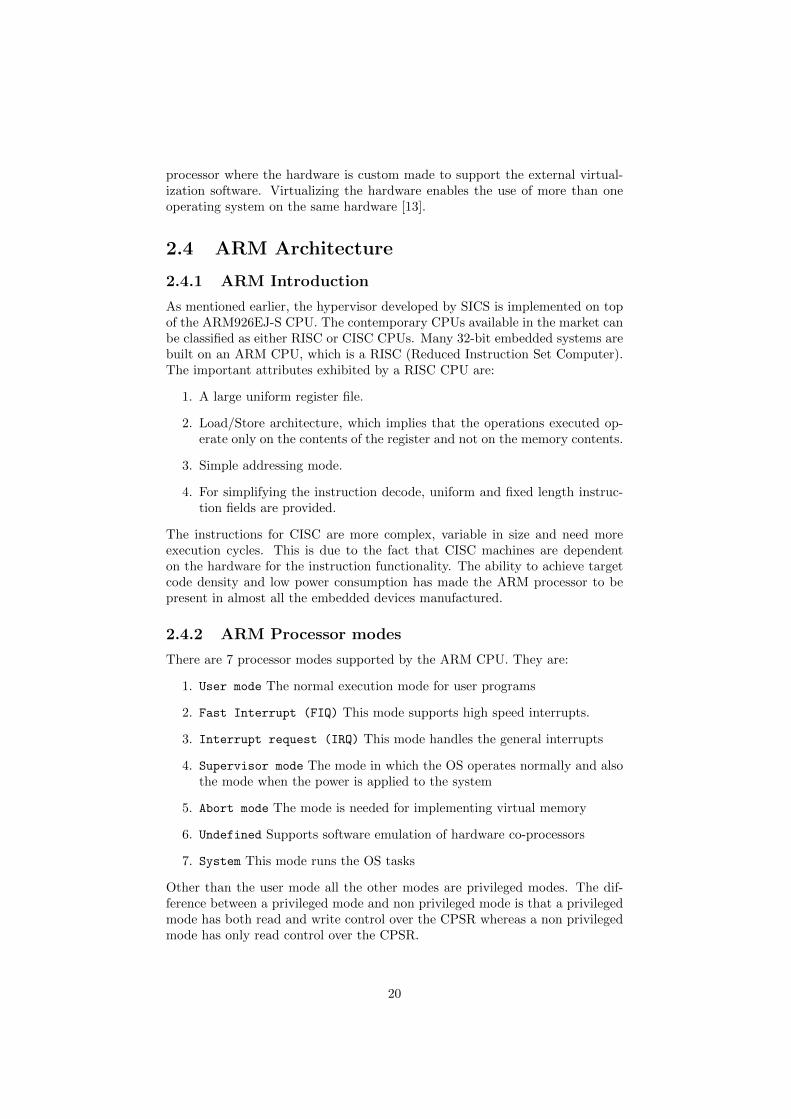
Table 2.1: Vector TableException/Interrupt Shorthand Address High Address
Reset RESET 0x00000000 0xffff0000Undefined instruction UNDEF 0x00000004 0xffff0004
Software interrupt SWI 0x00000008 0xffff0008Prefetch abort PABT 0x0000000c 0xffff000c
Data abort DABT 0x00000010 0xffff0010Reserved – 0x00000014 0xffff0014
Interrupt Request IRQ 0x00000018 0xffff0018Fast Interrupt request FIQ 0x0000001c 0xffff001c
2.4.6 ARM Coprocessor
The aim of adding coprocessors to a CPU core is to provide an extension tothe already existing instruction set of the CPU. Data transfer, memory transferinstructions, register transfer instructions are included in the coprocessor in-structions. Up to 16 coprocessors can be added to the ARM CPU, where the15th coprocessor is dedicated for the control functions. The control functionsinclude cache control, MMU and the TLB. It is important to know the func-tioning of the MMU in ARM which will provide a clear picture of the securityservices provided by the hypervisor.
22
2.4.7 MMU
The MMU is a hardware feature of the ARM co-processor which needs to behandled in order to achieve virtualization. The MMU converts the virtual ad-dresses provided by a compiler or linker into the physical addresses where theactual program is stored. As a result programs executes using the same virtualaddresses but using different physical addresses. If the MMU is disabled thenall the virtual addresses will be mapped one to one to the physical addresses.The MMU generates an abort exception when there is a translation failure,permission or domain faults.
As mentioned earlier, the virtual addresses must be translated before access-ing the memory. If the program tries to map the virtual address to physicaladdress individually, the entire process will be a cumbersome one. For makingthe translations easier, the MMU will divide the physical memory into contigu-ous sections called pages. The page table is the one which stores the virtualaddress to physical address mapping and access permissions to the memorypages.
2.4.8 Page Tables
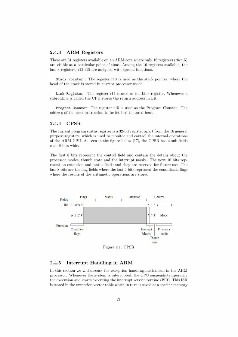
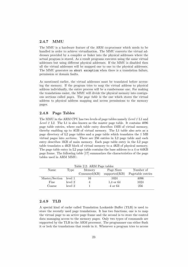
The MMU in the ARM CPU has two levels of page tables namely Level 1 L1 andLevel 2 L2. The L1 is also known as the master page table. It contains 4096page table entries, where each table entry describes 1MB of virtual memory,thereby enabling up to 4GB of virtual memory. The L1 table also acts as apage directory of L2 page tables and a page table which translates the 1 MBvirtual pages into sections. There are 256 entries in L2 page table and eachentry describes 1KB of main memory. Each page table entry in the L2 pagetable translates a 4KB block of virtual memory to a 4KB of physical memory.The page table entry in L2 page table contains the base address to a 4 or 64KBpage frame. The following table [17] summarizes the characteristics of the pagetables used in ARM MMU:
Table 2.2: ARM Page tablesName Type Memory Page Sizes Number of
Consumed(KB) supported(KB) Pagetable entries
Master/Section level 1 16 1024 4096Fine level 2 4 1,4 or 64 1024
Coarse level 2 1 4 or 64 256
2.4.9 TLB
A special kind of cache called Translation Lookaside Buffer (TLB) is used tostore the recently used page translations. It has two functions, one is to mapthe virtual page to an active page frame and the second is to store the controldata managing access to the memory pages. Only two types of commands aresupported by the TLB in the ARM processor. The programmer can either flushit or lock the translations that reside in it. Whenever a program tries to access
23
the memory, the MMU looks up the virtual page address values stored in thecache. If the lookup is successful then the TLB provides the translation of thephysical address and this is called as TLB hit. If the valid translation is notpresent in the TLB then it is defined as TLB miss. On a TLB miss, the pagetable provides the translation of the virtual to the physical address and this newtranslation is stored in the TLB. The register to be replaced is selected by theTLB in the ARM processor using the round robin algorithm.
24
List of Abbreviations
July 3, 2013
Chapter 3
Related Work
3.1 Hypervisors
A number of hypervisors are implemented and available on the market. In thischapter, we describe Xen which is widely used and serves as a good introductionto para-virtualization.
3.1.1 Xen Hypervisor
The Xen hypervisor, a free hypervisor licensed under the GNU general publiclicense was originally developed at Cambridge University. It can support theprocessors like x86, x86-64, Itanium, PowerPC, and ARM processor and OS likeLinux, NetBSD, FreeBSD, Solaris, Windows as guest operating systems runningon it.
Xen Architecture
The following are the vital components of the Xen environment [25].
1. Xen Hypervisor
2. Domain 0 guest
3. Domain U Guest (Dom U)
The Xen hypervisor, situated between the hardware and the operating sys-tems, is responsible for CPU scheduling and memory partitioning of the variousvirtual machines running on the CPU. Domain 0 [25] is a modified Linux kernel.It is a unique virtual machine running on the Xen hypervisor with special rightsto access physical I/O resources and it can also interact with the other virtualmachines. Running Domain 0 is a mandatory requirement by all Xen virtual-ization environments so that other virtual machines can be started for running.The Domain U is an unprivileged and has two subtypes. The Domain U PVGuests denotes all the para-virtualized virtual machines like modified LinuxOS, Solaris, FreeBSD etc., running on the Xen hypervsior. The Domain UHVM Guests denote all the fully virtualized virtual machines like WindowsOS. When hardware support is provided, a Domain U PV Guest differs froma Domain U HVM Guest, since it has been modified so that it does not accessdirectly the hardware.
1
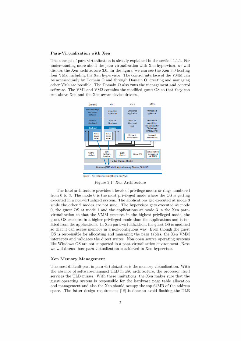
Para-Virtualization with Xen
The concept of para-virtualization is already explained in the section 1.1.1. Forunderstanding more about the para-virtualization with Xen hypervisor, we willdiscuss the Xen architecture 3.0. In the figure, we can see the Xen 3.0 hostingfour VMs, including the Xen hypervisor. The control interface of the VMM canbe accessed only by Domain O and through Domain O, creating and managingother VMs are possible. The Domain O also runs the management and controlsoftware. The VM1 and VM2 contains the modified guest OS so that they canrun above Xen and the Xen-aware device drivers.
Figure 3.1: Xen Architecture
The Intel architecture provides 4 levels of privilege modes or rings numberedfrom 0 to 3. The mode 0 is the most privileged mode where the OS is gettingexecuted in a non-virtualized system. The applications get executed at mode 3while the other 2 modes are not used. The hypervisor gets executed at mode0, the guest OS at mode 1 and the applications at mode 3 in the Xen para-virtualization so that the VMM executes in the highest privileged mode, theguest OS executes in a higher privileged mode than the applications and is iso-lated from the applications. In Xen para-virtualization, the guest OS is modifiedso that it can access memory in a non-contiguous way. Even though the guestOS is responsible for allocating and managing the page tables, the Xen VMMintercepts and validates the direct writes. Non open source operating systemslike Windows OS are not supported in a para-virtualization environment. Nextwe will discuss how para virtualization is achieved in Xen hypervisor.
Xen Memory Management
The most difficult part in para virtulaization is the memory virtualization. Withthe absence of software-managed TLB in x86 architecture, the processor itselfservices the TLB misses. With these limitations, the Xen makes sure that theguest operating system is responsible for the hardware page table allocationand management and also the Xen should occupy the top 64MB of the addressspace. The latter design requirement [18] is done to avoid flushing the TLB
2
while entering and leaving the hypervisor. But since we are dealing with theARM CPU, this memory virtualization is easier with the help of the softwaremanaged TLB provided by the ARM architecture. The reason behind this issoftware-managed TLB instructions are explicit and can be translated explicitly.
CPU Virtualization
Only two privileged levels are provided by most processor architectures, whichcreates a system where the modified guest operating system runs in the nonprivileged level. In ARM architecture, there are two processor modes whichare analogous to the privileged levels of the x86 CPU. They are a supervisormode with high priority and user mode with lesser priority. The x86 architec-ture virtualizes exceptions including the memory faults and software traps ina straightforward manner. For each type of exception, a table describing thehandler is registered with the Xen. Though the exception stack frames are leftunmodified [18] in the para virtualized system, the page fault handler has to bemodified.
The system call performance is increased by allowing each guest operating sys-tem to register for a fast exception handler. The processor can access this fastexception handler without indirecting via ring 0. This same technique cannotbe applied to the page fault handler because the faulting address from the reg-ister CR2 can only be read by the code executed in ring 0. By validating theexception handlers when they are presented to the Xen hypervisor, the systemsafety can be achieved.
3.2 Related porting work done
3.2.1 OpenBSD is ported on Fiasco
In this section we describe the modifications [15] done to run OpenBSD on topof Fiasco. In his thesis work, Christian Ludwig has described the methods tore-host the open BSD on the Fiasco micro-kernel. This fiasco is a L4 familyof micro-kernels. The L4 micro-kernel, proposed by Jochen Liedkte has thememory management unified with the IPC semantics which enabled user levelmemory management. Fiasco.OC and OKL4 from open kernel labs are exam-ples of various implementations of the L4 micro-kernel.
One modification [15] made to OpenBSD was changing the memory configura-tion for porting it.uvm(9) is the machine independent memory manager whichknows about the high level information. The machine dependent memory man-ager is called pmap and it has to be implemented in the architecture code ofthe OpenBSD kernel. The topmost gigabyte of every task is occupied by theFiasco micro-kernel which implies that the re-hosted OpenBSD kernel has to beimplemented as an user space application. The kernel has to be re-linked to anaddress below the Fiasco kernel memory space. Since the user space and kernelspace will be separated in the re-hosted system, the OpenBSD kernel will actas a L4 server by servicing OpenBSD applications separately.
The second modification [15] was changing the page tables on OpenBSD for
3
re-hosting it. Since the page tables cannot be directly reloaded on the MMU,the server has to maintain mappings of the page table and whenever there is achange on the page tables, inform the Fiasco to carry out the context switch.
3.3 freeRTOS porting to ARM based Hypervi-sor
In his thesis [3], Heradon Douglas explains the freeRTOS porting done on ARMbased hypervisor. For porting freeRTOS, three primary kernel source files wereidentified. Additional platform dependent code was also needed to port themon ARM platform. The additional code contains[3],
1. To set up the hardware, timer interrupt, establishing stacks in the memory,registering the kernel’s timer tick handler, populating exception vectorswe need low level boot and initialization code.
2. For saving and restoring the CPU context, enabling and disabling theinterrupts we need Assembler code.
3. Interrupt service routines for handling the interrupts
4. For allocating stack space to tasks, memory management code is needed
There were several issues identified and addressed while porting the freeR-TOS kernel to the ARM based hypervisor. These issues are explained here.
3.3.1 Interposition
As mentioned earlier, the hypervisor is designed to run in the privileged modewhile the modified guest OS and its tasks run in user mode. The designer has tomake sure that interposition between the hardware and freeRTOS is achievedby the hypervisor. The hypervisor also virtualizes the privileged operationsrequired by the kernel and the tasks. For enabling or disabling the interrupts[3], the platform dependent code is implemented though a hyper call.
3.3.2 Memory Protection
The freeRTOS kernel is designed such that each task runs in a privileged modeand the stack of the task gets a dynamically allocated block of memory. Thisblock of memory is allocated from the heap which is maintained by the kernel.That way, no virtual memory address space is allocated by the kernel for itstasks. Also, the tasks can access any memory in the system since there is noinbuilt memory protection. From this the system designer can come to threeconclusions[3]:
1. Since there is no table to shadow, the hypervisor does not need to supportany shadow page tables.
2. As there is no inbuilt memory protection, the hypervisor can be designedto provide memory protection.
4
3. If the hypervisor is located in the 32-bit address space as the kernel, thenTLB flushing is not needed as part of the context switch.
The memory space can be partitioned using the ARMv5 MMU, into domH,domK and domA. The domA contains the task memory and the domH is a clientdomain which is only accessible in privileged mode. The unmodified freeRTOSkernel contains the kernel and tasks running at the same privilege level and areimplemented as library calls. Now, the hypervisor should be designed such thatthese tasks should not tamper the kernel memory. This problem is addressedby using the wrapper mechanism by few ports of freeRTOS to systems witha Memory Protection Unit. When the wrapper mechanism is used, the taskscannot access the kernel directly and need to use a controlled wrapper functionto call the desired kernel function.
The next issue addressed in order to port the freeRTOS kernel onto the hy-pervisor is task protection. By separating the stack memory the tasks can beprotected from one another. To achieve this, the memory allocation code hasto be modified so that memory from different spaces are allocated to differenttasks. So, when a particular task gets executed, only that task’s domain for thestack will be enabled while disabling the other stack domains.
5
Chapter 4
OVP Installation and Setup
4.1 Introduction to OVP
OVP stands for Open Virtualization Platforms. It is an initiative, which aimsat making embedded software development easier on virtual platforms. Thisinitiative is made possible by the company called Imperas, which provides allthe needed infrastructure like free open source models, API documentation anda simulator for the virtual platforms. OVP is selected because of its features likeflexibility, powerful, ability to simulate custom hardware, efficient developmentand testing. The source code of much of the simulated hardware is availablefrom the OVP website which makes it more helpful in simulating an ARM basedsystem.
4.2 OVP Tools
In this chapter we will discuss the OVP tools needed, their installation andnecessary configuration. First of all, the entire tools required were installedin a Ubuntu OS running under an Oracle Virtualbox with Windows OS asthe host. Then the executable OVPsim.20111125.2.sfx is downloaded fromthe OVP website and installed from the command prompt using the com-mand ./OVPsim.20111125.2.sfx. We need to create a separate directory titledImperas.20111125 where the software is installed. Then the following executa-bles, OVPpse.toolchain.20111125.2.sfx andOVPsim_demo_linux_ArmIntegratorCP_arm_Cortex-A9UP.20111125.2.sfx aredownloaded and they are installed from the command prompt into the same di-rectory Imperas.20111125.
4.2.1 ARM Integrator/CP
The purpose of ARM Integrator/CP is to provide a flexible environment fordeveloping ARM based devices. With this board, one can model a product andallows hardware and software development. The baseboard is divided into twoparts [14]:
1. First is the baseboard providing the interface clocks, power, boot andmemory interfaces
6
2. Second is the core module providing the ARM core, SDRAM, SSRAM,memory and core clocks, and an FPGA that implements peripheral de-vices.
The purpose of installing the ARM Integrator/CP is to boot the Linux kernelported on the ARM processor and see the modifications made to the kernel forporting it.
4.2.2 Sourcery G++ Lite for ARM EABI
The Sourcery G++ Lite is CodeSourcery’s customized and validated versionof the GNU tool chain useful for building ARM based applications. C/C++compilers, assemblers, linkers, and libraries and anything else required for thedevelopment of the application is included in the tool chain.It provides the following features for programmers:
1. Running/Debugging the program in a simulator: Without the target hard-ware, one can run/debug the program written using the instruction setsimulator provided by Sourcery G++.
2. Debug Sprite to debug a program on the target: When the target hardwareis present one can load and execute the code written from the debugger,which is named as Debug Sprite.
3. Using a third party device to debug the program on the target: Thirdparty debugging device can be used to debug programs on the remotetarget. The communication between the remote target and the third partydebugging device takes place through the GDB remote serial protocol.
4.3 Server-Client Setup
For installing the OVP tools and running them in Ubuntu, we need to have alicense file which supports the server-client relationship between the host OSand Ubuntu OS. Since Windows OS is the host it will be the server and theclient will be the Ubuntu. The license file is placed in the server and the clientis connected to the server by running MSYS on the server. The MSYS standsfor Minimal System, which consists of GNU utilities like bash, grep etc neededfor building the programs which are dependent on UNIX tools. Once the msysterminal is displayed, we can navigate to the IMPERAS_ARCH folder and run thecommand lmgrd.exe -c /c/Imperas/OVPsim_float.lic -z. Now the serveris up and running and available to the client’s access.
From the Ubuntu terminal, we have to execute the following commands:source /home/master/OVP/Imperas.20111125/bin/setup.sh
setupImperas /home/master/OVP/Imperas.20111125/ which will set up theImperas environment variables.
Next is the important step for binding the server and client. For this we mustbe aware of the IP address of the server and run the following command inthe Ubuntu terminal, export IMPERASD_LICENSE_FILE=Port ID@IP Address
which will bind the server and the client.
7
Chapter 5
Kernel Modifications
5.1 SICS Hypervisor
Heradon Douglas [3] developed the SICS hypervisor in the year 2010 and thehypervisor was designed to run on the ARM926EJ-S CPU. Also, the freeRTOSkernel was modified and ported on the hypervisor. The final system had threeparts:
1. The core modified kernel
2. The code needed by the core kernel
3. The Hypervisor
To carry out the critical and low level tasks, the platform dependent code isneeded by the kernel. Note that after modification, the kernel will be runningin the less privileged level and hypervisor will be running in the most privilegedlevel. This means, all the privileged instructions were replaced by hypercallsand the platform dependent code of the guest OS is para-virtualized.
5.1.1 The Hypervisor
As mentioned earlier, the SICS hypervisor was developed for a particular ARMplatform. Hence, it contains boot code, exception handlers, and to allow the safeimplementation of critical platform dependant functionality it has the hypercallinterface. By having several virtual guest modes, multiple execution environ-ments are possible and these multiple environments are supported by the SICShypervisor. The hypervisor uses the MMU to provide the memory isolationbetween the different operating systems and its safety critical applications.
5.1.2 Hypervisor Modes
The number of guest modes supported by the hypervisor is arbitrary. Also, eachguest mode has its own memory configuration and execution context with thehypervisor controlling the guest mode under execution. The SICS hypervisorsupports 4 guest modes at present:
1. Kernel Mode for executing the kernel code
8
2. Task Mode for executing the application code
3. Trusted Mode for executing trusted code
4. Interrupt Mode for executing interrupt code
The ARMv7 architecture comes with new virtualization extensions and theseguest modes are no more necessary. The ARMv7 architecture provides a newexecution mode which has more priority than the supervisor mode. So, thehypervisor can execute in the new mode and the guest OS can execute with itsdefault privileges. This also removes the necessity for para-virtualization thussimplifying the design.
By having a linker script file, the designer can control the location of hyper-visor, kernel, task and trusted code in the memory. The hypervisor domain isonly accessible in privileged mode and this domain contains the hypervisor andthe critical devices. The hardware is set and the MMU is configured by the hy-pervisor when the system is booted. Initially the kernel applications run in theuser mode and when a hypercall is issued or hardware exception is encounteredtransition to the privileged mode takes place. This results in making sure thatonly the hypervisor can modify the memory configurations of the MMU.
The kernel contains the kernel code and the data required by the kernel code.After modifying the guest OS, the kernel APIs are wrapped around the collectionof wrapper functions, enter transition hypercall and exit transition hypercall toprotect the kernel from task applications. Those two transitions cause the guestOS mode to change from user mode to kernel mode, thereby providing a se-cure interface to use the kernel functions. When an exit transition hypercallis issued, the mode changes from privileged mode to the user mode. For thesecurity critical applications, a separate domain completely isolated from all theother domains is allotted. Remote Procedure Call (RPC) is the secure and welldefined interface provided to access all these secure services.
5.1.3 Hypercall Interface
Totally 11 hypercalls given the table 5.1 are provided by the hypervisor andthese hypercalls are used to access the privilege functions safely [2]. The termOrigin Restriction refers to where the origin of the hypercall is restricted by thehypervisor. The last 5 hypercalls can be issued by the tasks itself and hencethey require no origin restriction.As the name suggests, the EIN and DIN hypercalls are used to enable anddisable the interrupt. To save and restore the execution context, SCO and GCOhypercalls are used. To change from guest mode to kernel mode and change backto guest mode, Begin and End transition hypercall is used by the kernel wrapperfunctions. To ensure that a particular task is the only task with exclusive rightsto the shared resource in the critical section. When the particular task entersthe critical section, interrupts will be disabled by those hypercalls and enablethe interrupts at exit. When there are multiple guest modes, the RPC is used toachieve communication between those different guest modes. Starting the kernelscheduler or task yielding are the possible operations that can be made with the
9
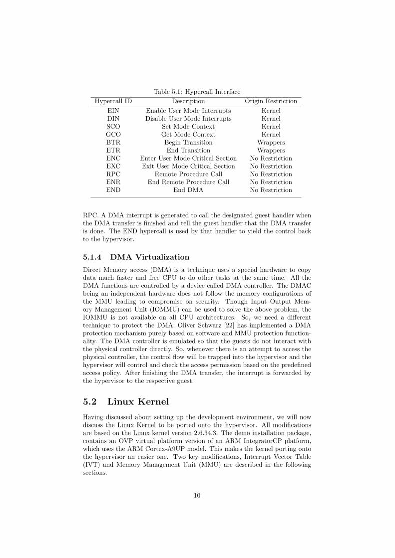
Table 5.1: Hypercall Interface
Hypercall ID Description Origin Restriction
EIN Enable User Mode Interrupts KernelDIN Disable User Mode Interrupts KernelSCO Set Mode Context KernelGCO Get Mode Context KernelBTR Begin Transition WrappersETR End Transition WrappersENC Enter User Mode Critical Section No RestrictionEXC Exit User Mode Critical Section No RestrictionRPC Remote Procedure Call No RestrictionENR End Remote Procedure Call No RestrictionEND End DMA No Restriction
RPC. A DMA interrupt is generated to call the designated guest handler whenthe DMA transfer is finished and tell the guest handler that the DMA transferis done. The END hypercall is used by that handler to yield the control backto the hypervisor.
5.1.4 DMA Virtualization
Direct Memory access (DMA) is a technique uses a special hardware to copydata much faster and free CPU to do other tasks at the same time. All theDMA functions are controlled by a device called DMA controller. The DMACbeing an independent hardware does not follow the memory configurations ofthe MMU leading to compromise on security. Though Input Output Mem-ory Management Unit (IOMMU) can be used to solve the above problem, theIOMMU is not available on all CPU architectures. So, we need a differenttechnique to protect the DMA. Oliver Schwarz [22] has implemented a DMAprotection mechanism purely based on software and MMU protection function-ality. The DMA controller is emulated so that the guests do not interact withthe physical controller directly. So, whenever there is an attempt to access thephysical controller, the control flow will be trapped into the hypervisor and thehypervisor will control and check the access permission based on the predefinedaccess policy. After finishing the DMA transfer, the interrupt is forwarded bythe hypervisor to the respective guest.
5.2 Linux Kernel
Having discussed about setting up the development environment, we will nowdiscuss the Linux Kernel to be ported onto the hypervisor. All modificationsare based on the Linux kernel version 2.6.34.3. The demo installation package,contains an OVP virtual platform version of an ARM IntegratorCP platform,which uses the ARM Cortex-A9UP model. This makes the kernel porting ontothe hypervisor an easier one. Two key modifications, Interrupt Vector Table(IVT) and Memory Management Unit (MMU) are described in the followingsections.
10
5.3 IVT and modification
As discussed already, there are 7 types of exceptions/interrupts, each one cantrigger transition from one mode to the other. We know that the guest operatingsystems interacts with the hypervisor by issuing hypercalls which are in turntreated as SWI (Software Interrupts) by the ARM CPU. So, we must modifythe interrupt vector table so that whenever a SWI is encountered, the CPUbranches to the address where the Interrupt Service Routine (ISR) for the SWIis stored. When an interrupt occurs the programmer takes the following actions:
1. Copy the CPSR to the supervisor mode SPSR, SPSR_SVC.
2. The CPSR mode bits are set so that it causes the mode change to super-visor mode
3. The IRQs are disabled by setting the IRQ bit. But still FIQs will beaccepted since the FIQ bit is not set.
4. The link register should be made to point to the next instruction to beexecuted. This is done by saving the value PC-4 into the Link Register inthe Supervisor mode
5. Now the PC is stored with the address 0x8, which is the address of theSWI handler
Also, to implement an interrupt service routine:
1. Interrupt Vector Table (IVT) of the Linux Kernel is identified in the fileentry-armv.S
2. The ISR is written in C language and stored in a separate file.
3. The IVT is modified so that the CPU branches to the address of the ISRwhenever there is a SWI
Now the following steps are followed to return from the SWI handler afterexecuting it:
1. The SPSR_SVC is copied back into the CPSR which restores the systembefore the SWI was encountered.
2. The value stored in the LR_SVC(Link Register in the Supervisor mode) ismoved back to the PC
The instruction MOVS pc, lr can accomplish the above mentioned return ac-tion in a single instruction. In the privileged mode, the MOVS instruction copiesthe SPSR to CPSR provided, the return address is stored in the register r14and the destination register is the PC. The programmer must also ensure that,when a SWI calls another SWI ie nested handlers, then the Link Register(LR)and SPSR must be stacked before branching to the nested SWI. This should bedone to avoid corruption of the LR and SPSR values.
The IVT consist of the ARM instructions which can manipulate the PC to jumpto a specific address to handle an interrupt or exception. The IVT starts at theaddress 0x00000000 and the SWI handler is stored in the address 0x00000008.Now after writing the SWI handler, we must modify the IVT accordingly sothat when the SWI is encountered, the corresponding handler is called.
11
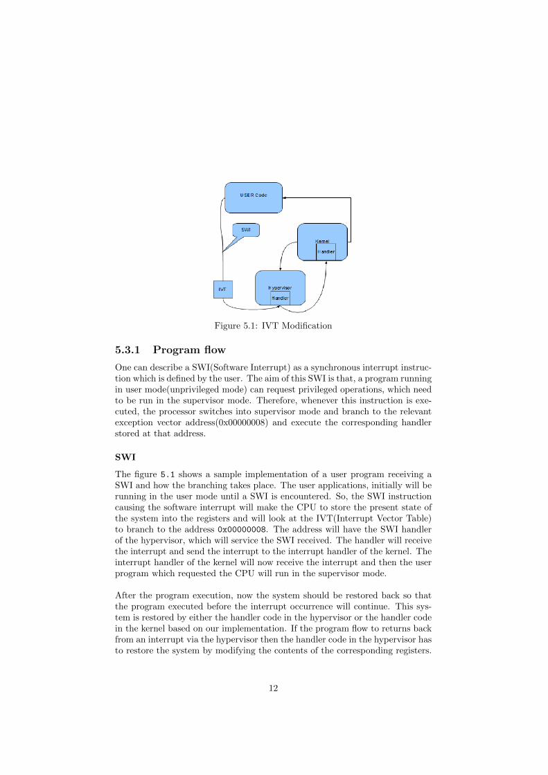
Figure 5.1: IVT Modification
5.3.1 Program flow
One can describe a SWI(Software Interrupt) as a synchronous interrupt instruc-tion which is defined by the user. The aim of this SWI is that, a program runningin user mode(unprivileged mode) can request privileged operations, which needto be run in the supervisor mode. Therefore, whenever this instruction is exe-cuted, the processor switches into supervisor mode and branch to the relevantexception vector address(0x00000008) and execute the corresponding handlerstored at that address.
SWI
The figure 5.1 shows a sample implementation of a user program receiving aSWI and how the branching takes place. The user applications, initially will berunning in the user mode until a SWI is encountered. So, the SWI instructioncausing the software interrupt will make the CPU to store the present state ofthe system into the registers and will look at the IVT(Interrupt Vector Table)to branch to the address 0x00000008. The address will have the SWI handlerof the hypervisor, which will service the SWI received. The handler will receivethe interrupt and send the interrupt to the interrupt handler of the kernel. Theinterrupt handler of the kernel will now receive the interrupt and then the userprogram which requested the CPU will run in the supervisor mode.
After the program execution, now the system should be restored back so thatthe program executed before the interrupt occurrence will continue. This sys-tem is restored by either the handler code in the hypervisor or the handler codein the kernel based on our implementation. If the program flow to returns backfrom an interrupt via the hypervisor then the handler code in the hypervisor hasto restore the system by modifying the contents of the corresponding registers.
12
Otherwise, if the program flow returns back from an interrupt from the kernel,then the handler code in the kernel is responsible for restoring the system bymodifying the corresponding registers.
5.4 Page Tables
The hypervisor is designed to run at the privileged level of the processor. Hence,virtualizing the Memory Management Unit(MMU) and the Input Output Mem-ory Management Unit(IOMMU) of the CPU is the best way to protect them[23]. This CPU based virtualization is better when compared to software basedvirtualization because it will reduce the code size of the hypervisor and minimalchanges are required to port OS kernels to run on the hypervisor. The pagetables can be used as the basis of the MMU based memory protections sincethe page tables are supported by a large number of CPU architectures. We canfollow either of the these two ways to protect the page tables.
1. Keeping the page tables in the address space of the hypervisor and allowingthe kernel to read and modify it through safe function calls.
2. Virtualizing the physical memory. The result is the addresses sent on thememory bus are different from the physical addresses seen by the kernel[23]. So, the page tables responsible for translating the kernel’s physicaladdresses to the actual physical addresses seen on the memory bus shouldbe kept in the hypervisor’s address space and should be maintained bythe hypervisor. One more important point to note is that the kernel isnot aware of the virtualization of the physical memory.
Each method mentioned above has its own advantages and disadvantages.
1. In the first method using the function call interface, the kernel directlywrites in to the page tables. As a result there is no synchronization over-head and this is the faster method. This method will make changes to thekernel’s page table handling code leading to increase in the time requiredfor porting a new kernel to the hypervisor.
2. The second method is secure and allows easy porting of a kernel to thehypervisor. This is slow due to the synchronization overhead.
Since we are particular about security and easy portability, the second methodie to virtualize the physical memory is preferred.
Configuring the shared address space
In any OS, the kernel is the first program that gets executed when the system isbooted. So, a part of the kernel memory is made executable by the initializationof the page tables by the hypervisor. The same address space is shared by theuser and kernel memories in most of the operating systems and sharing thesame address space makes the control flow of the kernel to execute user codewith kernel privilege vulnerable to an external modification. The shared addressspace should be configured in a way that prevents any external modification.The programmer has to take care that the hypervisor modifies the page table sothat the user memory is executable when the CPU is in the user mode and not
13
executable when the CPU is in the kernel mode[23]. Also, all the transitionsmodifying the user memory execute permissions in the page table, taking placebetween the user and kernel mode must be intercepted by the hypervisor. Thehypervisor sets the execution permissions only for the memory of the mode thatis getting executed currently in the page table.
Protecting Write and Execute permissions
Only the approved code is made executable by the hypervisor which sets theexecution rights in the page tables. For this, when the processor enters the kernelmode, an instruction pointer is set to an address in the approved code. Thereare certain entry points through which the processor enters the kernel modeand the information about these entry points are informed by the kernel to theprocessor. The addresses of those entry points are written into the processorregisters and data structures like IVT. Those entry points are virtualized by thehypervisor and only is allowed to operate on them[23]. For virtualizing the entrypoints, safe function calls are provided by the hypervisor to the kernel throughwhich those entry points are read and modified. This will lead to a situationwhere, whenever there is an attempt to execute the not approved code in thekernel mode, an exception will be generated by the processor. This exceptiongenerated will cause the OS termination by the hypervisor and also the approvedcode pages in the page table are marked read-only by the hypervisor preventingany external modifications[23]. Also, the programmer has to make sure that thekernel memory pages in the kernel mode are either writable or executable butnot both.
Protecting DMA writes
There are situations where writing by a DMA can modify the approved codepages in the page table. To avoid such modifications, the hypervisor must usethe DMA write protection functionality of the IOMMU to protect the approvedpages in the page table[23]. This DMA write protection along with the read-onlyprotection makes sure that only the hypervisor modifies the memory containingthe approved code and no modifications are done by any code running on theCPU.
14
Chapter 6
Conclusion and FutureWork
6.1 Conclusion
This thesis explains the necessary background details required for porting aLinux Kernel onto the SICS hypervisor. In the first half of the thesis, settingup the OVP tools, ARM IntegratorCP, the development environment are dis-cussed. Compiling and Building the Linux kernel image using the OVP toolsare detailed. In the second half of the thesis, adding system calls in the Linuxkernel, Linux kernel’s interrupt vector tables are explained. Two major modifi-cations for the Linux kernel for porting it on to the hypervisor are described inthe 5th chapter.
Also, when the freeRTOS kernel was ported onto the hypervisor, tests werecarried to calculate the performance overhead. Using a thin hypervisor on anembedded platform resulted in a minimum overhead which was acceptable giventhe security of the system is improved. So, when the Linux OS is ported therewill be minimal performance overhead with a more secure system.
6.2 Future Work
The future work may consist of two parts. First is to list out the remainingmodifications to be done and the second is to implement those modificationson the kernel. Simulating the kenel using the OVP tools, comparing the resultsbefore and after porting to analyze the impact of porting also needed to bedone.
15
Bibliography
[1] Linux Device Drivers. O’REILLY, 2005.
[2] Viktor Do. Security services on an optimized thin hypervisor for embeddedsystems. Master’s thesis, Lunds Tekniska Hogskola, 2011.
[3] Heradon Douglas. Thin hypervisor-based security architectures for embed-ded platforms. Master’s thesis, The Royal Institute of Technology, Stock-holm, Sweden, 2010.
[4] George Dunlap. The Paravirtualization Spectrum, part 1: The Endsof the Spectrum. http://blog.xen.org/index.php/2012/10/23/
the-paravirtualization-spectrum-part-1-the-ends-of-the-spectrum,2012. [Online; accessed 02-April-2013].
[5] William Gatliff. The linux kernel?s memory management unit api, 2001.
[6] Gernot Heiser. The role of virtualization in embedded systems. In FirstWorkshop on Isolation and Integration in Embedded Systems, number ACM978-1-60558-126-2. IIES’08, Open Kernel Labs and NICTA and Universityof New South Wales Sydney, Australia, 2008.
[7] Bill Hill. Intro to Virtualization: Hardware, Software, Memory, Stor-age, Data and Network Virtualization Defined. http://www.petri.co.il/intro-to-virtualization.htm#hardware-virtualization, 2012. [On-line; accessed 30-December-2012].
[8] Thom Holwerda. Kernel designs explained. http://www.osnews.com/
files/17537/kernel\_designs\_explained.pdf, March 2007. [Online;accessed 13-April-2013].
[9] Intel Inc. Introduction to embedded systems. http://www.intel.com/
education/highered/Embedded/Syllabus/Embedded\_syllabus.pdf.
[10] M. Tim Jones. Virtualization for embedded systems. publisher, 2011.
[11] Cuong Hoang H. Le. Protecting xen hypercalls intrusion detection/ pre-vention in a virtualization environment. Master’s thesis, The University ofBritish Columbia, 2009.
[12] John L.Hennessy and David A.Patterson. Computer Architecture A Quan-titative Approach. Morgan Kaufmann, 4th edition edition, 2007.
16
[13] John Lister. What Is Hardware Virtualization? http://www.wisegeek.
com/what-is-hardware-virtualization.htm, 2008-2013. [Online; ac-cessed 13-April-2013].
[14] ARM Ltd. Integrator/CP Compact Platform Baseboard HBI-0086. ARMLtd, 2002.
[15] Christian Ludwig. Porting openbsd to fiasco. Technical report, 2011.
[16] Jelena Mamcenko. Lecture Notes On OPERATING SYSTEMS, chapter 2.Vilnius Gediminas Technical University, year.
[17] Andrew N.Sloss, Dominic Symes, and Chris Wright. ARM System Devel-oper’s guide Designing and Optimizing System Software.
[18] Keir Fraser Steven Hand Tim Harris Alex Ho Rolf Neugebauery Ian PrattAndrew Warfield Paul Barham, Boris Dragovic. Xen and the art of virtual-ization. Technical report, University of Cambridge Computer Laboratory,2003.
[19] Benjamin Roch. Monolithic vs microkernel. IEEE Multimedia.
[20] Margaret Rouse. Para-virtualization. http://searchservervirtualization.techtarget.com/definition/paravirtualization.Online; accessed 30-July-2012.
[21] Margaret Rouse. Virtualization. http://searchservervirtualization.techtarget.com/definition/virtualization,2010. Online; accessed 27-July-2012.
[22] Oliver Schwarz and Christian Gehrmann. Securing dma through virtu-alization. In Proceedings of the 2nd IEEE International Conference onComplexity in Engineering, 2012.
[23] Arvind Seshadri, Mark Luk, Ning Qu, and Adrian Perrig. Secvisor: A tinyhypervisor to provide lifetime kernel code integrity for commodity oses.Technical report.
[24] VMware. Understanding Full Virtualization, Paravirtualization, and Hard-ware Assist. VMware Inc, 2007.
[25] Xen. How does xen work. pages 3–5, December 2009.
17


![Hypervisor Introspection - Bitdefender · Hypervisor Introspection Détecter les attaques ciblées avec l’introspection de l‘hyperviseur [2] Guides et solutions Sommaire 1. Aperçu](https://static.fdocument.pub/doc/165x107/5f765c2213e0df36e237adb0/hypervisor-introspection-bitdefender-hypervisor-introspection-dtecter-les-attaques.jpg)