Plasma antenna
29
PLASMA ANTENNA REPRESENTED BY ADITYA KUMAR TRIPATHY REGD NO-1241019150 BRANCH-EI&CE SEC-A
-
Upload
aditya-kumar-tripathy -
Category
Engineering
-
view
834 -
download
1
Transcript of Plasma antenna
PLASMA ANTENNA
REPRESENTED BYADITYA KUMAR TRIPATHY
REGD NO-1241019150BRANCH-EI&CE
SEC-A

OUTLINE
1. Introduction.2. What is plasma?3. What is plasma antenna?4. How does Plasma antenna work?5. Working principle.6. Pros and Cons.7. Scope.8. Conclusion.
05/01/2023 2
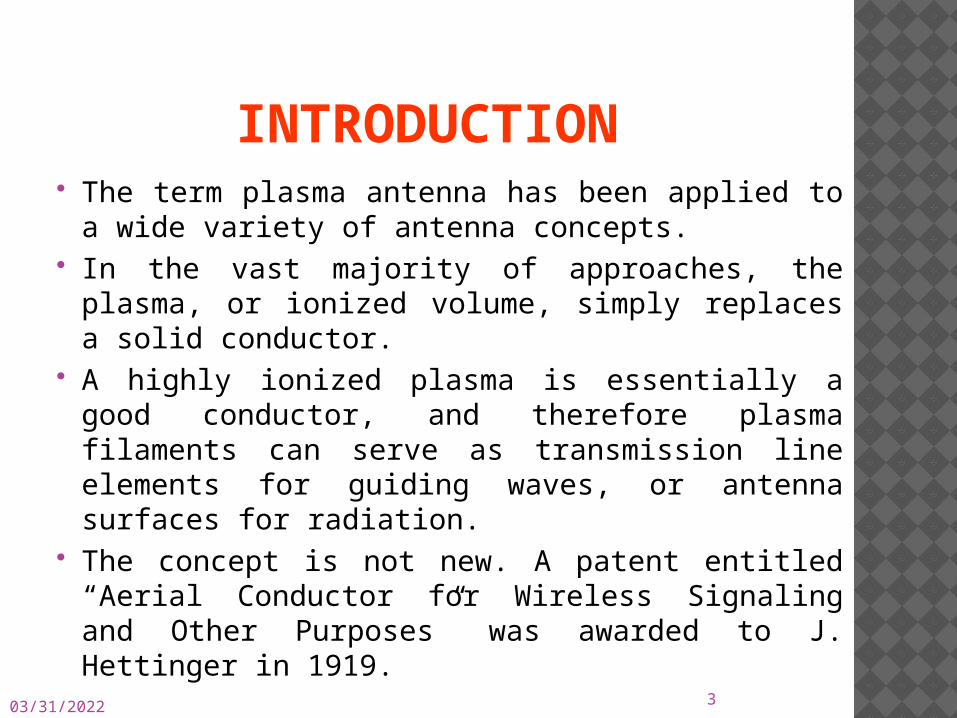
INTRODUCTION The term plasma antenna has been applied to a
wide variety of antenna concepts. In the vast majority of approaches, the plasma,
or ionized volume, simply replaces a solid conductor.
A highly ionized plasma is essentially a good conductor, and therefore plasma filaments can serve as transmission line elements for guiding waves, or antenna surfaces for radiation.
The concept is not new. A patent entitled “Aerial Conductor for Wireless Signaling and Other Purposes” was awarded to J. Hettinger in 1919.
05/01/2023 3
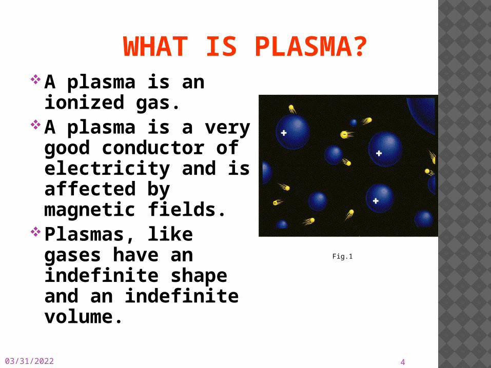
WHAT IS PLASMA?A plasma is an
ionized gas.A plasma is a very
good conductor of electricity and is affected by magnetic fields.
Plasmas, like gases have an indefinite shape and an indefinite volume.
05/01/2023 4
Fig.1
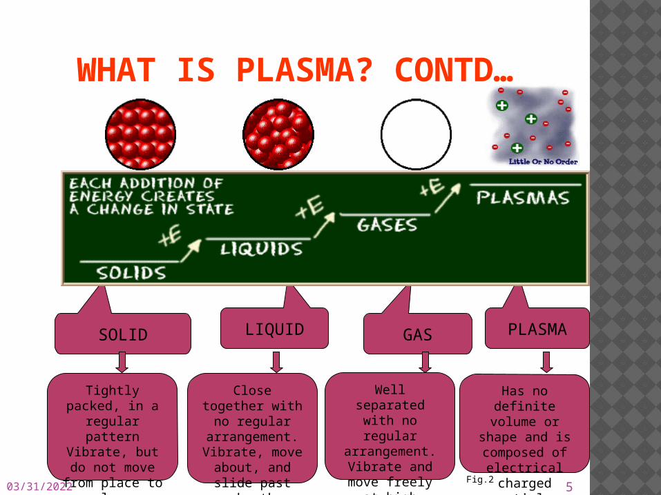
WHAT IS PLASMA? CONTD…
SOLID LIQUID GAS PLASMA
Tightly packed, in a regular
patternVibrate, but do not move from place to place
Close together with no regular arrangement.Vibrate, move
about, and slide past each other
Well separated with no regular arrangement.Vibrate and
move freely at high speeds
Has no definite volume or
shape and is composed of
electrical charged particles05/01/2023 5
Fig.2
05/01/2023 6
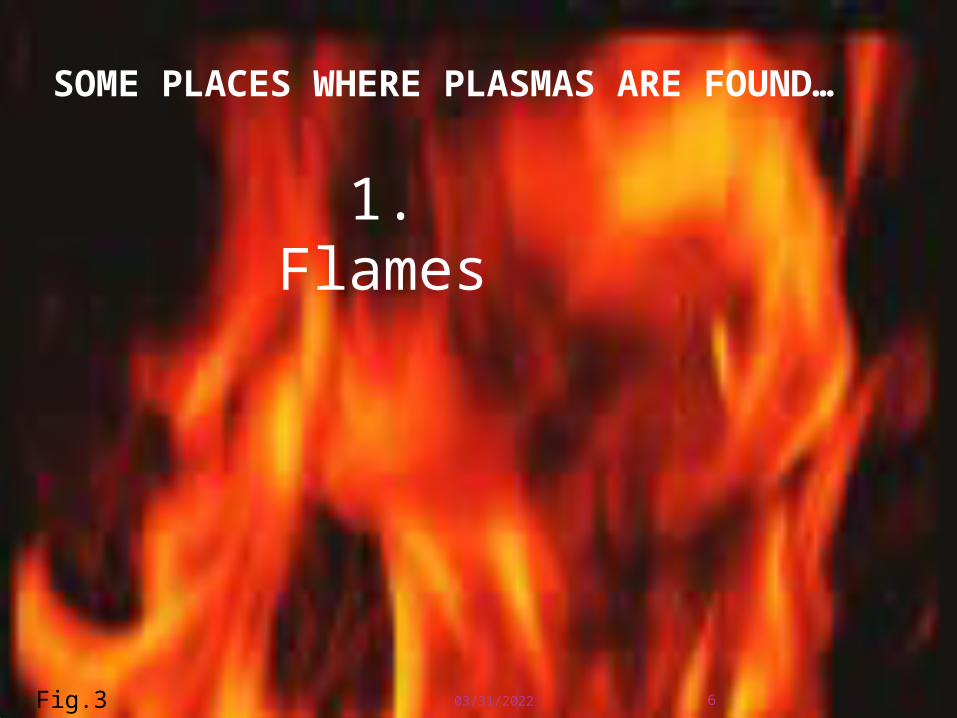
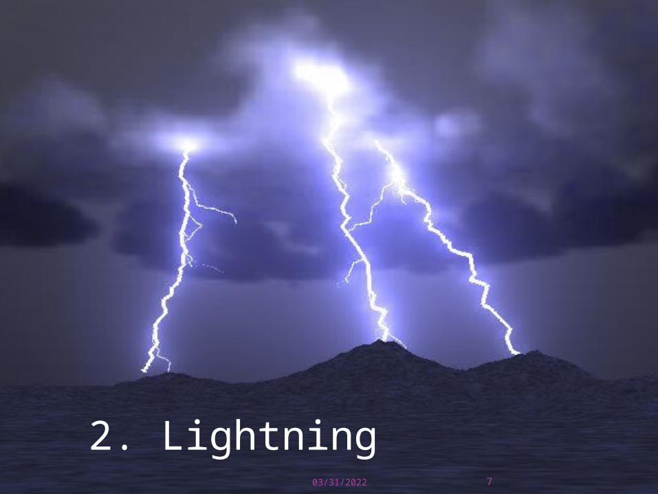
SOME PLACES WHERE PLASMAS ARE FOUND…
1. Flames
Fig.3
05/01/2023 7
2. LightningFig.4
05/01/2023 8
3. Aurora (Northern Lights)
Fig.5

05/01/2023 9
The Sun is an example of a star in its plasma state
Fig.6
WHAT IS PLASMA ANTENNA?
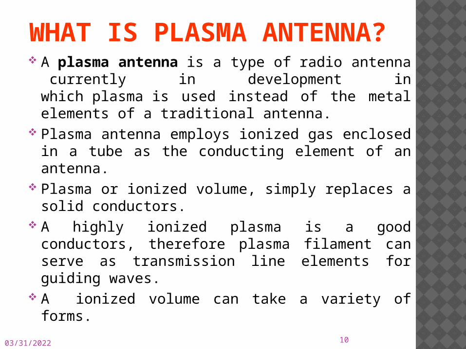
A plasma antenna is a type of radio antenna currently in development in which plasma is used instead of the metal elements of a traditional antenna.
Plasma antenna employs ionized gas enclosed in a tube as the conducting element of an antenna.
Plasma or ionized volume, simply replaces a solid conductors.
A highly ionized plasma is a good conductors, therefore plasma filament can serve as transmission line elements for guiding waves.
A ionized volume can take a variety of forms.
05/01/2023 10
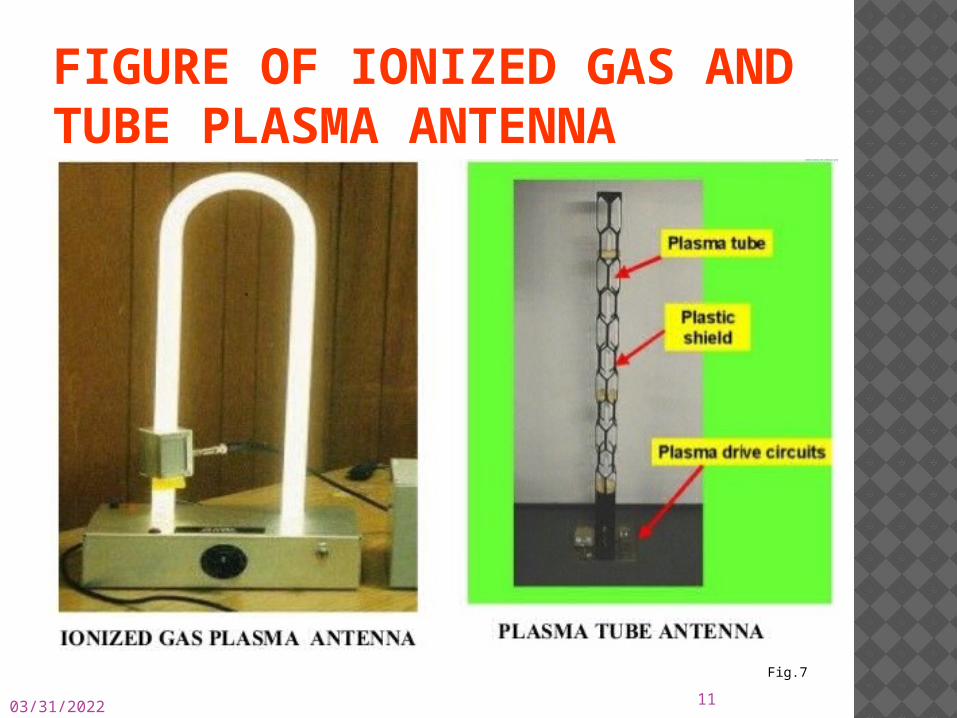
FIGURE OF IONIZED GAS AND TUBE PLASMA ANTENNA
05/01/2023 11Fig.7
05/01/2023
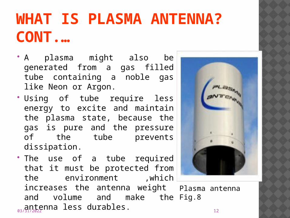
WHAT IS PLASMA ANTENNA? CONT.… A plasma might also be
generated from a gas filled tube containing a noble gas like Neon or Argon.
Using of tube require less energy to excite and maintain the plasma state, because the gas is pure and the pressure of the tube prevents dissipation.
The use of a tube required that it must be protected from the environment ,which increases the antenna weight and volume and make the antenna less durables.
12
Plasma antenna Fig.8
05/01/2023 13
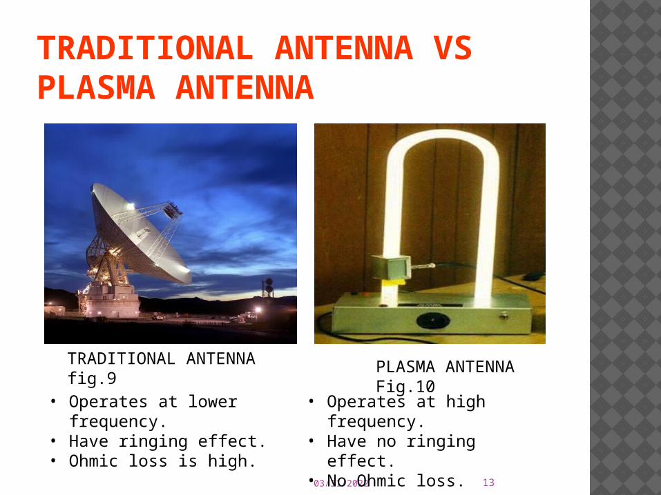
TRADITIONAL ANTENNA VS PLASMA ANTENNA
• Operates at high frequency.
• Have no ringing effect.• No Ohmic loss.
• Operates at lower frequency.
• Have ringing effect.• Ohmic loss is high.
TRADITIONAL ANTENNA fig.9 PLASMA ANTENNA
Fig.10
HOW DOES PLASMA ANTENNA WORK?When supply is given to the tube, the
gas inside it gets ionized to plasma.When plasma is highly energized, it
behaves as a conductor.Antenna generates a localized
concentration of plasma to form a plasma mirror that deflects RF beam launched from a central feed located at focus of mirror.
05/01/2023 14

STRUCTURE OF PLASMA ANTENNA EXCITED BY HIGH VOLTAGE
05/01/2023 15Experimental setup Fig.11
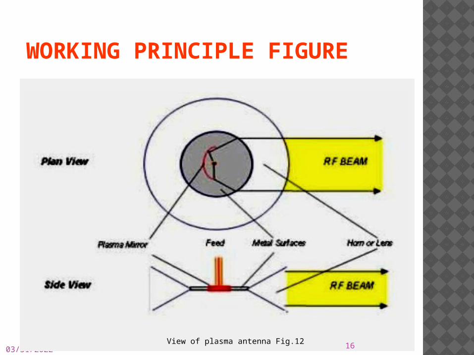
WORKING PRINCIPLE FIGURE
05/01/2023 16View of plasma antenna Fig.12
GENERATION OF ELECTRIC AND MAGNETIC FIELD When voltage applied to an antenna,
electric field is applied. It causes current to flow in antenna. Due to current flow ,magnetic field is
produced. These two fields are emitted from an
antenna and propagate through space over very long distance.
05/01/2023 17
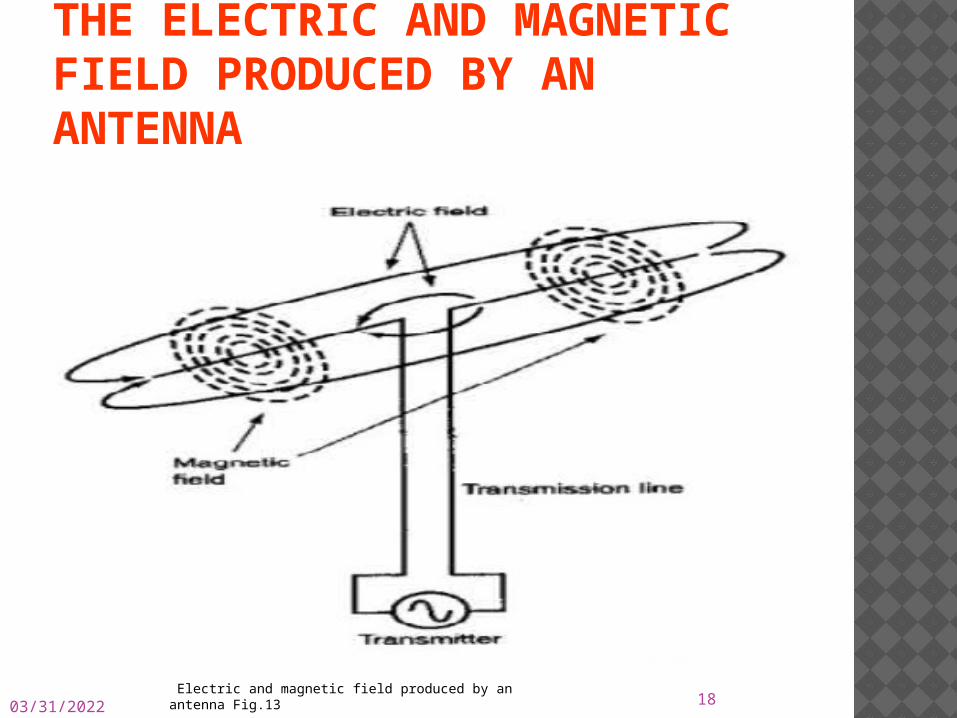
THE ELECTRIC AND MAGNETIC FIELD PRODUCED BY AN ANTENNA
05/01/2023 18 Electric and magnetic field produced by an antenna Fig.13
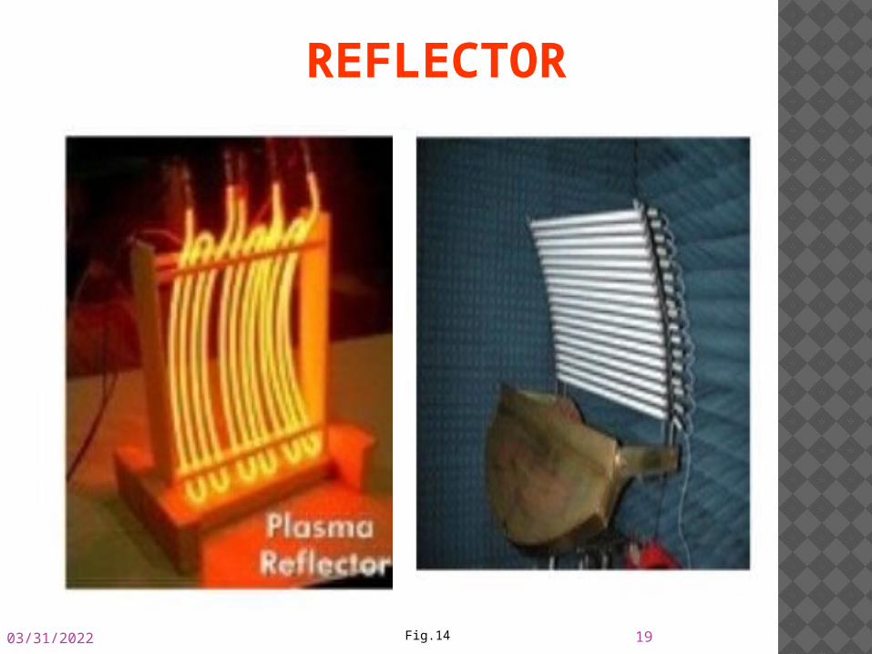
REFLECTOR
05/01/2023 19Fig.14
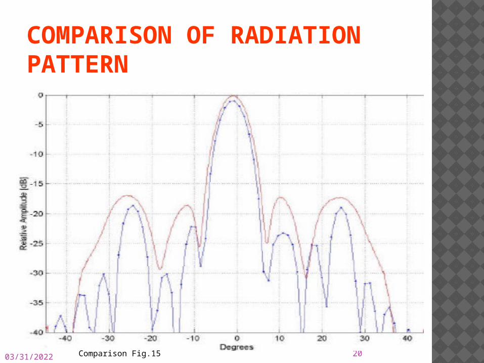
COMPARISON OF RADIATION PATTERN
05/01/2023 20Comparison Fig.15
05/01/2023 21
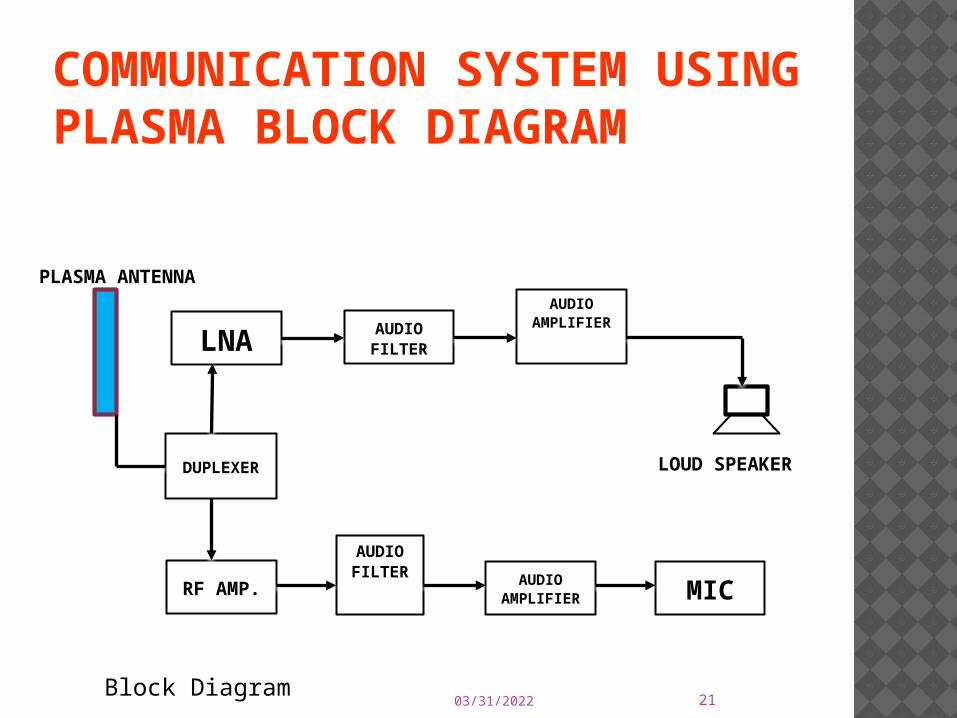
COMMUNICATION SYSTEM USING PLASMA BLOCK DIAGRAM
DUPLEXER
LNA AUDIO FILTER
AUDIO AMPLIFIER
RF AMP.
AUDIO FILTER
AUDIO
AMPLIFIER MIC
PLASMA ANTENNA
LOUD SPEAKER
Block Diagram
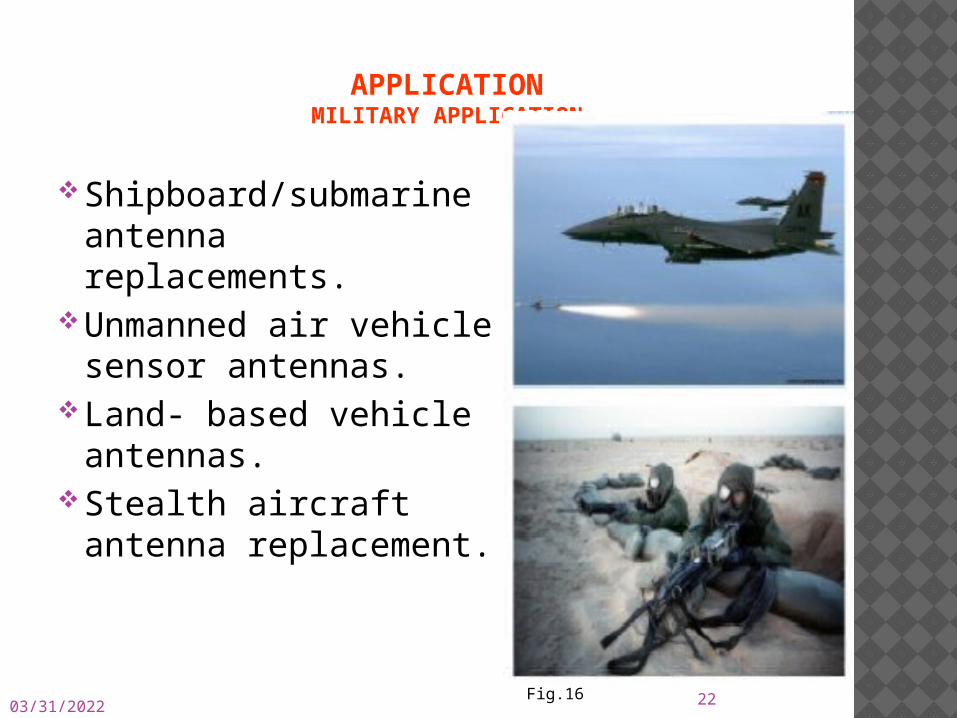
APPLICATIONMILITARY APPLICATION
Shipboard/submarine antenna replacements.
Unmanned air vehicle sensor antennas.
Land- based vehicle antennas.
Stealth aircraft antenna replacement.
05/01/2023 22Fig.16
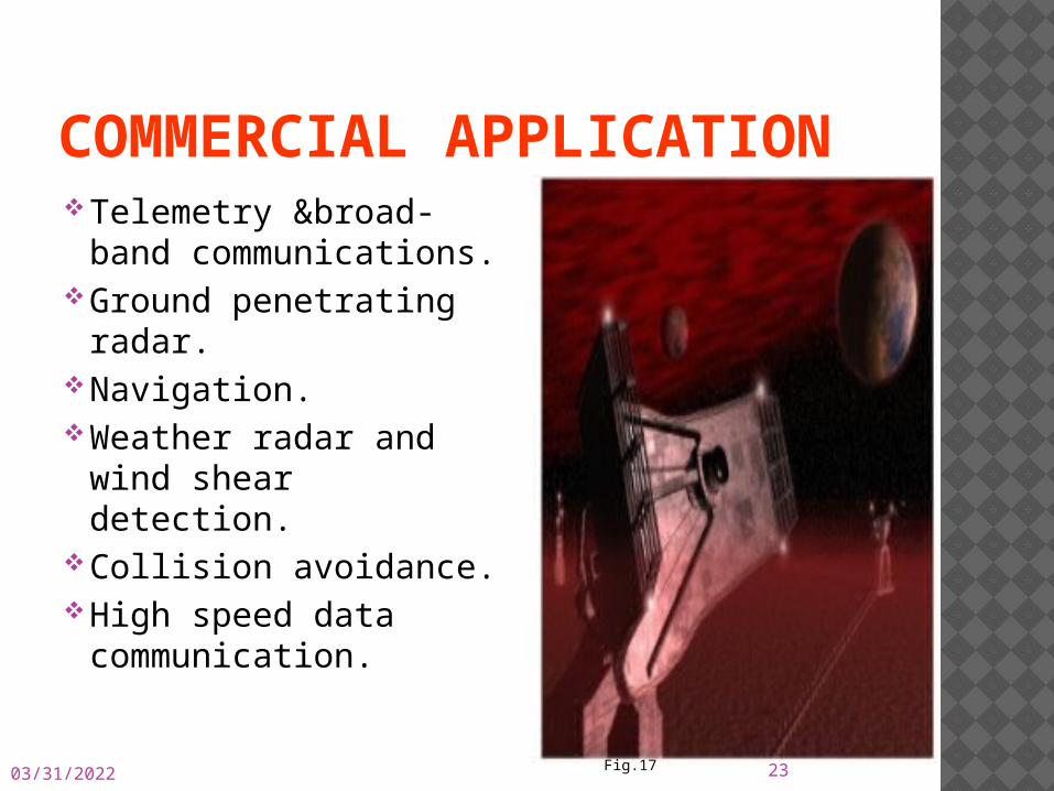
COMMERCIAL APPLICATION Telemetry &broad-
band communications. Ground penetrating
radar. Navigation. Weather radar and
wind shear detection. Collision avoidance. High speed data
communication.
05/01/2023 23Fig.17

PROS & CONS The length of an ionized filament can be
change rapidly, thereby ‘returning’ the antenna to a new frequency.
The antenna can be ‘turned off’ to make it electrically invisible. This reduce scattering and eliminating coupling, interference with other nearby antenna.
High gain.Wide band width.Compact and light weight.Maintenance free. It can operate up to 20GHZ.
05/01/2023 24
PROS & CONSPlasma volumes must be stable and
repeatable. when a gas is ionized, not all 100% of gas will ionize to become plasma.
The ionizer increases power consumption, more energy is required to ionize the gases or to make the silicon chips release electrons. Therefore, plasma antennas actually use more power than normal antennas.
05/01/2023 25
SCOPE The future of high-frequency, high-speed wireless
communications could very well be plasma antennas capable of transmitting focus radio waves that would quickly dissipate using conventional antennas. Thus, plasma antennas might be able to revolutionize not just high-speed wireless communications.
Higher frequencies mean shorter wavelengths and hence smaller antennas. The antenna actually becomes cheaper with the smaller size.
Plasma antenna to be used for next generation Wi-Gig (its version 1.0 was announced in December 2009) that can reach up to 7 Gbps bandwidth over frequencies up to 60 GHz.
05/01/2023 26
CONCLUSION The plasma antenna works according to the
same principles and physics laws as the normal antenna, with plasma replacing the metal conductors of the normal antenna.
But because the conducting material used is plasma, it affords some advantages over a normal antenna.
The most notable advantage of the plasma antenna is the fact that it is practically invisible to radar and can release short pulses of signals.
Therefore, the military US is currently racing to implement the plasma antenna into their exciting systems.
05/01/2023 27

REFERENCES[1]. Plasma Antennas – G.G. Borg et. Al.,
Phys. Plasmas 7, 2198, (2000).; I.Alexeff et. Al., IEEE Trans. Plasma Sci., vol. 34,
no. 2, pp 166-172, April2006; Igor Alexeff et. Al., Phys. Plasmas 15, 1,
2008.[2]. Plasma Lenses - P. Linardakis, Borg., G.
and Martin, N.Electron. Lett. 42, 444 (2006).[3]. Plasma Frequency Selective Surfaces – I.
Alexeff etal., IEEE Trans. Plasma Sci., vol. 35, no. 2, pp
407-415, April 2007.05/01/2023 28

05/01/2023 29