Photonic Crystal Resonators and Light Emitters - CMU · Photonic Crystal Resonators and Light...
23
Photonic Crystal Resonators and Light Emitters Yong H. Lee Department of Physics, KAIST http://pbg.kaist.ac.kr
Transcript of Photonic Crystal Resonators and Light Emitters - CMU · Photonic Crystal Resonators and Light...

Photonic Crystal Resonatorsand Light Emitters
Yong H. Lee
Department of Physics, KAIST
http://pbg.kaist.ac.kr

Contents
1. Wavelength-size Laser2. Electrical Single-cell Photonic
Crystal Laser3. µ-fiber Coupled Photonic
Crystal Laser4. Summary

Wavelength-size Laser
Strong Photon Confinement in Very Small Volume
2-D Slab Photonic Crystal
The Smallest Laser ?
λ/2
VCSEL 2D PBG Laser
(λ/2n)3
Ultimate Laser- V ~ (λ/2n)3
- High Speed
- High Efficiency

1.00.10.01E-3E-4
Monopole Mode
1. λ-scale
2. Low-loss
3. Nondegenerate
4. Central-zero
H. G. Park, et al., Appl. Phys. Lett. 79, 3032 (2001).

Introduction of Central Post
2rp
central node
A post does not affect Q factor significantly !!!
Q = ωτp

r =0.35a, r’ = 0.25a, a = 540nmt =0.37a, rp= 0.5a, 1.0a
dp
Single-cell Resonator with Post
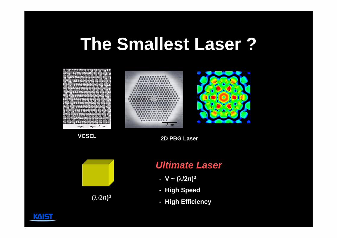
Experiments:Single-cell Cavity with Central Post
• Optical pumping @ ~1% duty cycle
• Quadrupole mode

Electrically-driven Photonic Crystal Laser
Dr. Hong-Gyu Park (Harvard)
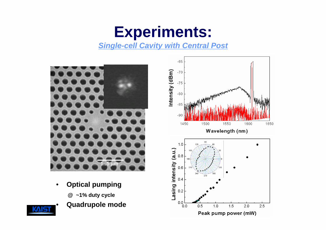
Current Injection Scheme
• Highly-doped n-i-p structure: mobility of electron > mobility of hole
dielectric material
p-InP substrate
p-InP post
nip
InGaAsP slab
tip (current injection)

Fabricated e-PBG Resonator
Top view Cross-sectional view
H. G. Park et al., Science, vol. 305, 1444 (2004)
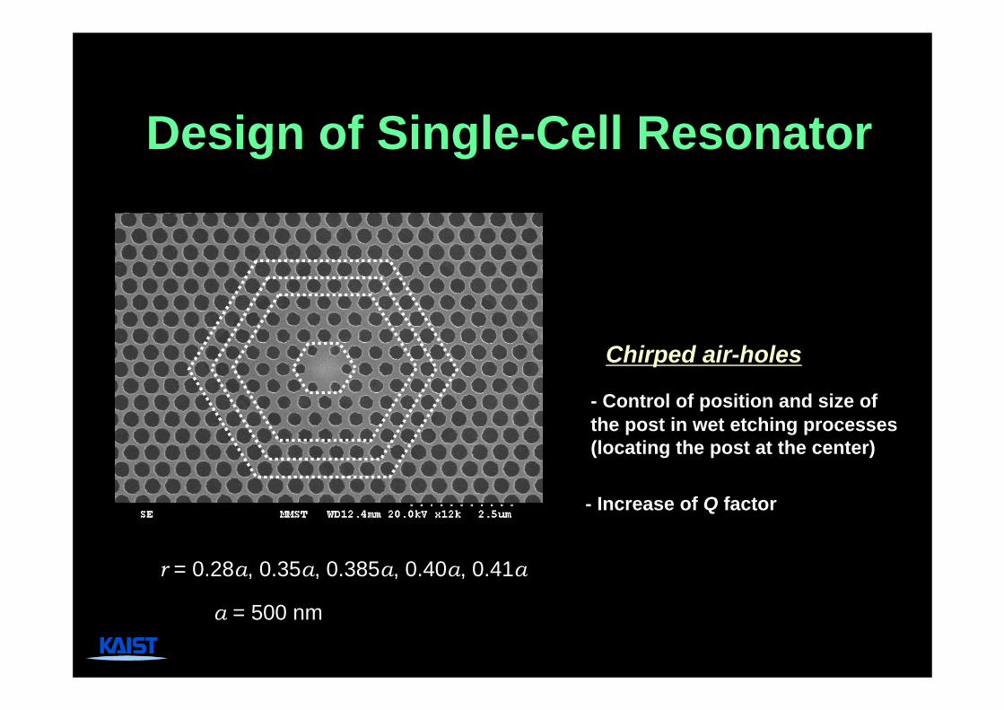
Design of Single-Cell Resonator
- Control of position and size of the post in wet etching processes (locating the post at the center)
- Increase of Q factor
r = 0.28a, 0.35a, 0.385a, 0.40a, 0.41a
a = 500 nm
Chirped air-holes
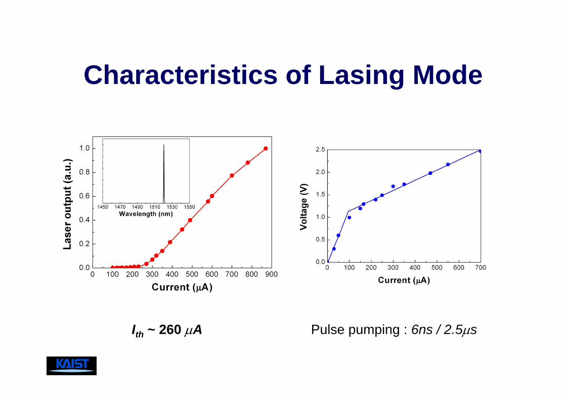
Characteristics of Lasing Mode
Pulse pumping : 6ns / 2.5µsIth ~ 260 µA

Confirmation: The Monopole Mode
Experimental measurements agree well with 3D FDTD computations based on structural data taken directly from the SEM picture.
<CCD near-field image> <Calculated Poynting vector> <Calculated E-intensity>
H. G. Park et al., Science, vol. 305, 1444 (2004)

Spontaneous Emission Factor β
• Record-high β value
• Effective carrier localization by electrical pumping
• Nondegenerate monopole mode
• Small modal volume
β ~0.25

µ-fiber CoupledPhotonic Crystal Laser
Prof. In-Gak Hwang (Chun Nam University)

Curved µ-fiber Coupling
250 µm
1 µmModified PC cavitydesigned for efficient fiber coupling
µ-fiber- D ~1.3 µm - Curvature ~ 1/50 µm-1
Optical I/O

+ better phase matching (along x)-modified linear cavity
+ larger mode overlap (along y)−µ-fiber
original cavity
Ey− 0 +
modifiedcavity
Microfiber
(a = 430 nm, r=0.35)
(a = 500 nm, r=0.35:0.30:0.25)x
y
z
y
Qint ~ Qair = 26000.
λ /neff
Modified Linear PhC Cavity

0 50 100 150 200 250 300
0
5
10
15
Pfib
er1 (
nW)
Peak pump power (µW)
1450 1500 1550 1600
30 dB
Wavelength (nm)
PC Laser with Fiber I/O
Pfiber1
WDMcoupler
Pfiber2
single-mode fiber
980 nmpump
PC laser
All-fiber PC laser- Low threshold of 35 µW- High output power of >10 nW
- Extremely local pumping- Highly efficient out-coupling
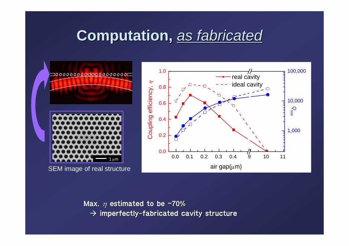
Max. Max. ηη estimated to be ~70% estimated to be ~70%
imperfectlyimperfectly--fabricated cavity structurefabricated cavity structure
1 µm
SEM image of real structure
0.0 0.1 0.2 0.3 0.4 9 10 110.0
0.2
0.4
0.6
0.8
1.0 real cavity ideal cavity
Qtotal
air gap(µm)
Cou
plin
g ef
ficie
ncy,
η
1,000
10,000
100,000
Computation, Computation, as fabricatedas fabricated

To Close

Toward the Ultimate Photon Source
– (λ/n)3, High-Q Resonator (Q/V)– QD Active Material– Photon Out-coupling– Reliable Current Injection Scheme– Strong Coupling Regime / Cavity QED– On-demand Single Photon Gun ?
For more information, visit, http://pbg.kaist.ac.kr

The TeamKAIST
http://pbg.kaist.ac.kr
– I. K. Hwang– H. G. Park (Harvard)– S. H. Kwon– K. H. Kim – S. H. Kim– S. K. Kim– J. K. Yang– H. J. Chang– M. K. Seo– F. Huyssen
ETRI- J. S. Kim - S. B. Kim
Financial Supporters:
1. National Research Laboratory Project, Korea
2. National R&D Project for Nano Science and Technology, Korea
3. AOARD-05-4-69, USA
NTT Lab- M. Notomi
Samsung- I. Kim
CEA- J-M Gerard


![Title Periodic FMMs and Calderon's preconditioning in acoustics … · 2016. 6. 20. · and metamaterials [10] in optics. The photonic crystal, for instance, is a periodic structure](https://static.fdocument.pub/doc/165x107/5fbd40de7967a66f4302dc28/title-periodic-fmms-and-calderons-preconditioning-in-acoustics-2016-6-20-and.jpg)