PART IV. EXTERNAL TANK - NASA · PART IV. EXTERNAL TANK Introduction The external tank ......
54
SPACE TRANSPORTATION SYSTEM HAER No. TX-116 Page 283 PART IV. EXTERNAL TANK Introduction The external tank (ET) was the largest element of the STS and the only non-reusable major component. The complete ET structure measured approximately 154’ in length, more than 30’ longer than the orbiter. Since it was expendable, the ET was designed “to minimize active or moving parts.” 1225 The ET contained and delivered approximately 1.6 million pounds of propellants (fuel and oxidizer) for the three SSMEs. The LO2 oxidizer was held in a forward tank, while the larger, rear tank contained the LH2 fuel. A structural connector called the intertank separated the two propellant tanks. In addition to serving as the shuttle’s “fuel tank,” the ET also was the backbone structure for attachment of the orbiter and SRBs. It accommodated the stresses created by both its own weight and that of the orbiter prior to launch, as well as the stresses generated by the SSMEs and SRBs during launch. The ET was designed by the Martin Marietta Corporation, and manufactured and assembled by the Lockheed Martin Space Systems Company 1226 at NASA’s government owned - contractor operated Michoud Assembly Facility (MAF) in New Orleans, Louisiana. 1227 The ET program was managed by the ET Project Office at MSFC. Lockheed Martin had approximately 2,000 subcontractors and suppliers located across the United States who provided materials for the ET. Historically, the suppliers included the Aluminum Company of America for SRB attachment fittings, ball forgings, longerons, forward ogive forgings and diagonal struts; both Reynolds Metals and Kaiser Industries Corporation for machined aluminum for LH2 tank barrel panels; Kaman Aerospace for slosh baffle segments; Aerochem for LO2 tank barrel panels; and Aircraft Hydroforming, Inc. for gore and ogive panels, as well as outer, inner and intermediate chords. 1228 Historical Overview Early Design Concepts The tank design concepts developed in the late 1960s for the USAF Flight Dynamics Laboratory foreshadowed the Shuttle ET designs of the early 1970s. Both Lockheed and McDonnell Douglas submitted their early designs, prepared for the USAF, to NASA as part of the Phase A 1225 Martin Marietta Corporation, System Definition Handbook, Space Shuttle External Tank (Lightweight Model), Configuration & Operation Volume I, (New Orleans, LA: Martin Marietta Corporation, August 1980), III-5, MSFC History Office, Huntsville. 1226 In March 1995, the Martin Marietta Corporation and Lockheed Corporation merged to form the Lockheed Martin Corporation. 1227 MAF was previously used for building the first stage of the Saturn IB and Saturn V rockets for the Apollo Program. 1228 Edward H. Kolcum, “Space Shuttle Lightweight Tank Production Begins,” Aviation Week & Space Technology, November 16, 1981: 135.
Transcript of PART IV. EXTERNAL TANK - NASA · PART IV. EXTERNAL TANK Introduction The external tank ......

SPACE TRANSPORTATION SYSTEM HAER No. TX-116 Page 283
PART IV. EXTERNAL TANK Introduction The external tank (ET) was the largest element of the STS and the only non-reusable major component. The complete ET structure measured approximately 154’ in length, more than 30’ longer than the orbiter. Since it was expendable, the ET was designed “to minimize active or moving parts.”1225 The ET contained and delivered approximately 1.6 million pounds of propellants (fuel and oxidizer) for the three SSMEs. The LO2 oxidizer was held in a forward tank, while the larger, rear tank contained the LH2 fuel. A structural connector called the intertank separated the two propellant tanks. In addition to serving as the shuttle’s “fuel tank,” the ET also was the backbone structure for attachment of the orbiter and SRBs. It accommodated the stresses created by both its own weight and that of the orbiter prior to launch, as well as the stresses generated by the SSMEs and SRBs during launch. The ET was designed by the Martin Marietta Corporation, and manufactured and assembled by the Lockheed Martin Space Systems Company1226 at NASA’s government owned - contractor operated Michoud Assembly Facility (MAF) in New Orleans, Louisiana.1227 The ET program was managed by the ET Project Office at MSFC. Lockheed Martin had approximately 2,000 subcontractors and suppliers located across the United States who provided materials for the ET. Historically, the suppliers included the Aluminum Company of America for SRB attachment fittings, ball forgings, longerons, forward ogive forgings and diagonal struts; both Reynolds Metals and Kaiser Industries Corporation for machined aluminum for LH2 tank barrel panels; Kaman Aerospace for slosh baffle segments; Aerochem for LO2 tank barrel panels; and Aircraft Hydroforming, Inc. for gore and ogive panels, as well as outer, inner and intermediate chords.1228 Historical Overview Early Design Concepts The tank design concepts developed in the late 1960s for the USAF Flight Dynamics Laboratory foreshadowed the Shuttle ET designs of the early 1970s. Both Lockheed and McDonnell Douglas submitted their early designs, prepared for the USAF, to NASA as part of the Phase A
1225 Martin Marietta Corporation, System Definition Handbook, Space Shuttle External Tank (Lightweight Model), Configuration & Operation Volume I, (New Orleans, LA: Martin Marietta Corporation, August 1980), III-5, MSFC History Office, Huntsville. 1226 In March 1995, the Martin Marietta Corporation and Lockheed Corporation merged to form the Lockheed Martin Corporation. 1227 MAF was previously used for building the first stage of the Saturn IB and Saturn V rockets for the Apollo Program. 1228 Edward H. Kolcum, “Space Shuttle Lightweight Tank Production Begins,” Aviation Week & Space Technology, November 16, 1981: 135.
SPACE TRANSPORTATION SYSTEM HAER No. TX-116 Page 284
Space Shuttle competition.1229 The Star Clipper vehicle concept developed by Lockheed included two 23.67’-diameter fuel tanks that formed a “vee” around the orbiter’s nose. This represented the first major concept that moved part of the propellants (LH2 fuel) externally into expendable tanks.1230 The Model 176, developed by McDonnell Douglas for the USAF study, used parallel fuel tanks with both LH2 fuel and LO2 oxidizer tanks located external to the orbiter. The two 150’-long x 24’-diameter fuel tanks were mounted on either side of the orbiter, and the 73’-long oxidizer tanks were attached on the orbiter’s top and bottom.1231 NASA augmented the Phase B Space Shuttle study efforts in April 1971, with the addition of an analysis of an external hydrogen tank for the orbiter of a fully reusable shuttle.1232 As a result, a new task was added to the existing McDonnell Douglas and North American Rockwell Phase B study contracts, as well as to the Lockheed Phase A Alternate Shuttle Concepts contract. A final report for the expendable LH2 tank prepared by each contractor was submitted between June 25 and June 30, 1971.1233 In May 1971, NASA had made the decision to put both the LO2 and LH2 tanks outside the orbiter airframe. “As with all shuttle components, cost was of primary importance in tank design.”1234 The intended consequence was to reduce total Shuttle development costs by half, and within the range considered supportable by Congress.1235 An expendable ET allowed the orbiter to be smaller and lighter, and with less costly TPS materials.1236 The original design requirements for the ET were written by Rockwell International, NASA’s orbiter and systems integration contractor. At this time, the program mission model called for 445 flights at the rate of sixty per year. According to Myron Pessin, former Chief Engineer for the External Tank Project at MSFC, the RFP developed by the ET Project Office, headed by James Odom, was based on the requirements prepared by Lockheed. Accordingly, “because of the high build rate envisioned, major attention was given to features to encourage low cost production approaches.”1237 Additionally, “ET design and processes had to be optimized for high rate production.”1238
1229 Jenkins, Space Shuttle, 68-69. 1230 Jenkins, Space Shuttle, 68. 1231 Jenkins, Space Shuttle, 69. 1232 Whalen and McKinley, “Chronology,” 11. 1233 Whalen and McKinley, “Chronology,” 13. 1234 Dunar and Waring, Power to Explore, 292. 1235 Dunar and Waring, Power to Explore, 283. 1236 Jenkins, Space Shuttle, 140. 1237 Myron A. Pessin, “Lessons Learned From Space Shuttle External Tank Development – A Technical History of the External Tank,” (technical history, NASA MSFC, October 30, 2002), 2. 1238 Myron A. Pessin, interview by Rebecca Wright, NASA STS Recordation Oral History Project, June 30, 2010, http://www.jsc.nasa.gov/history/oral_histories/STS-R/PessinMA/PessinMA_6-30-10.htm.
SPACE TRANSPORTATION SYSTEM HAER No. TX-116 Page 285
Contract Awards The ET was the third major procurement for the STS, following the award of initial contracts for the orbiter and the SSME. Following a series of reviews and presentations for prospective contractors, held at MSFC on September 7, 1972, December 12, 1972, and March 6, 1973, the RFP for the DDT&E of the Shuttle ET was released to industry on April 2, 1973.1239 This procurement included the manufacture of three ground test tanks (Structural Test Article, Propulsion Test Article, and Dynamic Test Article) and six developmental flight tanks (ET-1 through ET-6), with the last delivery in 1979.1240 Four companies were invited to bid: the McDonnell Douglas Astronautics Company of Huntington Beach, California; the Boeing Company of Seattle, Washington; the Chrysler Corporation Space Division of New Orleans, Louisiana; and Martin Marietta Aerospace, Denver Division.1241 Because it had been selected by NASA as the prime orbiter contractor, Rockwell was prohibited from proposing on the ET contract. However, this firm teamed with Chrysler to provide a joint bid.1242 In March 1973, appointments were made to the Space Shuttle ET Project Source Evaluation Board, which was co-chaired by Robert E. Lindstrom, Director of the Shuttle Office at MSFC, and James R. Odom, ET Project Manager.1243 By the end of May, NASA received a proposal from each contractor team. On August 16, 1973, NASA announced the selection of Martin Marietta for the ET DDT&E contract.1244 A letter contract was executed on September 1, 1973. The period of performance for this initial contract (No. NAS8-30300), valued at roughly $40.5 million, ran through December 16, 1974. A letter contract extending the period of performance through January 31, 1975, with no increase in price, was approved by NASA Headquarters on November 25, 1974.1245 By January 1975, NASA and the contractor “agreed on terms for a $156.565 million cost-plus-award-fee contract.”1246 Martin Marietta subcontracted the manufacture of the intertank aluminum panels to Avco Corporation’s Aerostructures Division of Nashville, Tennessee. The $3.2 million contract between Martin Marietta and Avco was signed on June 11, 1975. Work was
1239 Whalen and McKinley, “Chronology,” 22-24; “Shuttle Tank Effort,” Marshall Star, March 14, 1973, 2; “Space Shuttle External Tank Proposals Released,” Marshall Star, April 4, 1973, 1, 4. 1240 “Martin-Marietta to develop Space Shuttle Tank,” NASA News Release No. 73-163, August 16, 1973, Folder: Space Shuttle-External Tank #1 1972-1973, MSFC History Office, Huntsville. 1241 “NASA Asks Proposals for Shuttle ET,” NASA News Release No. 73-64, April 2, 1973, Folder: Space Shuttle-External Tank #1 1972-1973, MSFC History Office, Huntsville. 1242 Jenkins, Space Shuttle, 187. 1243 James B. Odom, interview by Rebecca Wright, NASA STS Recordation Oral History Project, July 20, 2010, http://www.jsc.nasa.gov/history/oral_histories/STS-R/OdomJB/OdomJB_7-20-10.htm. 1244 “Martin Marietta to develop Space Shuttle External Tank,” Marshall Star, August 29, 1973, 2. 1245 “Letter contract extension,” no date, Programs/Projects: Space Shuttle, Drawer 23, Folder: Shuttle-External Tank August-December 1974, MSFC History Office, Huntsville. 1246 Dunar and Waring, Power to Explore, 302.
SPACE TRANSPORTATION SYSTEM HAER No. TX-116 Page 286
slated to begin during the latter half of 1975 on ten intertank units, with delivery scheduled for late 1978.1247 At the time of RFP release, the shuttle systems requirements, including the orbiter tile design, had not been finalized. Later, as the systems requirements matured, design changes to the ET were needed, especially to the TPS materials and their locations.1248 The Space Shuttle ET Project Requirement Review Board, chaired by Mr. Odom, met at MSFC in early February 1974, to define the program and technical requirements for subsequent design and development. All aspects of the STS hardware interfaces, ET subsystems, test and verification, and flight operations were addressed.1249 A major discussion point at this time was the proposal to increase by 1,000 pounds the ET control weight of 75,000 pounds. In a note to Dr. William R. Lucas, Director of MSFC (1974-1986), Shuttle Program Manager Robert (Bob) Lindstrom reported that “The loads situation of Shuttle continues to be serious – our most recent ET loads will give us a few hundred pounds impact plus a cost and schedule penalty.”1250 Robert Thompson, Manager of the Space Shuttle Program Office at JSC (1970-1981), expressed concern for all shuttle element weights. As a result, the “Level II management reserve at MECO of 7,000 pounds” was established “to be used to implement new requirements or tradeoffs among element weight . . .”1251 Reducing the weight of the ET to enable increased payload capacity was a continued concern throughout the SSP. On August 28, 1974, NASA awarded a $26,453,600 contract to Martin Marietta for ET contract support through August 31, 1978. This four-year facilities contract provided for the acquisition of plant equipment at MAF, rehabilitation of existing facilities, and construction, modification, maintenance, and repair of facilities.1252 This contract was amended on February 17, 1977, with the provision of approximately $3.7 million to fund construction of one new facility plus the addition of Cell D to the Vertical Assembly Building. The amended facilities contract also provided for the continuation of previously authorized facility work.1253 According to James Odom, “the buying and the designing of the tooling was extremely crucial to the success of the program.”1254 He estimated NASA’s original investment in specialized tooling at about $900 million.
1247 “Nashville Firm Gets $32 Million Shuttle Contract,” Marshall Star, June 18, 1975, 4. 1248 Pessin, “Lessons Learned,” 3. 1249 “Shuttle ET Review Being Held Here,” Marshall Star, January 30, 1974, 1, 2. 1250 Bob Lindstrom to Dr. Lucas, December 23, 1974, Programs/Projects: Space Shuttle, Drawer 23, Folder: Shuttle-External Tank Aug-Dec 1974, MSFC History Office, Huntsville. 1251 Robert F. Thompson to Manager, Shuttle Projects Office, MSFC, August 14, 1974, Programs/Projects: Space Shuttle, Drawer 23, Folder: Shuttle-External Tank Aug-Dec 1974, MSFC History Office, Huntsville. 1252 “MSFC Awards Support Contract to Martin Marietta,” NASA MSFC News Release No. 74-157, August 28, 1974, Programs/Projects: Space Shuttle, Drawer 23, Folder: Shuttle-External Tank Aug-Dec 1974, MSFC History Office, Huntsville; Whalen and McKinley, “Chronology,” 30. 1253 Whalen and McKinley, “Chronology,” 46-47. 1254 Odom, interview.
SPACE TRANSPORTATION SYSTEM HAER No. TX-116 Page 287
NASA’s second major contract with Martin Marietta, valued at $230 million, was awarded in July 1980, for the beginning of full-scale flight tank production to support Shuttle operations. It covered delivery of seven ETs, and provided long lead time procurement for components and subassemblies for five additional tanks and raw material for nineteen more units.1255 Effective to this contract, NASA’s MSFC applied its amendment to the existing ET DDT&E contract with Martin Marietta to add more than $42.9 million to cover weight reduction redesign and development efforts and to modify tooling to be used in future production. The redesign was in accordance with NASA’s plan to reduce the weight of the ET by 6,000 pounds to permit increased payload carrying capacity. Under this new contract, the first lightweight ET was expected to be delivered in the summer of 1982.1256 Production Buys 2 through 4 (Contract No. NAS8-33708) for fifty-four operational flight tanks and related launch site and flight support, covered the period between June 30, 1980 and June 3, 1991. The value at the end of this contract was $2,225.9 million. Production Buy 5 (Contract No. NAS8-36200) was for the manufacture, assembly, test, checkout, and delivery of thirty-five lightweight tanks plus twenty-five super lightweight tanks. The $3,773.0 million contract covered the period between November 2, 1984, and September 30, 2002. Production Buy 6 (Contract No. NAS8-00016, Schedule A), valued at $908.3 million, covered thirty-five flight tanks plus support for the period of September 27, 1999 through January 29, 2006. Following the Columbia accident, this contract was replaced by Schedule F, which called for the manufacture, assembly, test, checkout and delivery of nineteen tanks, between January 30, 2006, and September 30, 2010. The production portion of this contract was valued at $996.9 million.1257 Cumulatively, Lockheed Martin’s ET contract with NASA was valued at approximately $11 billion. Approximately 70 percent of the funds committed to the external tank went to subcontractors, most of whom supplied materials to Lockheed Martin.1258 ET Test Programs In his technical history of the ET, Myron Pessin described five types of development test programs. These included materials testing, components testing, structural tests, dynamic tests, and propulsion tests. A summary of each follows.
1255 “ET Production Contract Let,” Marshall Star, July 2, 1980, 1; “NASA Awards Martin Marietta $230 Million Contract for Production of Shuttle External Tanks,” NASA News, MSFC, Release No. 80-90, Programs/Projects: Space Shuttle, Drawer 23, Folder: ET 1979 and 19809, MSFC History Office, Huntsville. 1256 “External Tank to be Lightened,” Marshall Star, July 2, 1980, 1. 1257 NASA MSFC, Transition Project Office, “STS Stack Recordation Data Package,” June 15, 2009. 1258 Dunar and Waring, Power to Explore, 303.
SPACE TRANSPORTATION SYSTEM HAER No. TX-116 Page 288
Materials and Components Tests According to Pessin, the primary focus of the materials test program was the thermal protection materials, including foam insulation and ablators.1259 Foams were tested under realistic flight conditions in wind tunnels at the USAF’s Arnold Engineering Development Center in Tennessee, and ablators were tested in the plasma arc jets at Ames. Unique tests of spray-on foam insulation (SOFI) were conducted at Eglin Air Force Base in Florida. SOFI testing at Eglin made use of a 10’-diameter tank filled with liquid nitrogen and “subjected to various rain, wind, humidity and temperature conditions to determine the rate of ice growth.”1260 These data were later incorporated into a computer program used at KSC to predict whether ice would form during tanking or would exist prior to launch. During 1976, MSFC engineers used an aluminum “mini-tank” to test the TPS for the LH2 tank. Thirteen tanks, each coated with SOFI, were tested to evaluate the ability of the insulation to withstand various types of stress during launch and flight. Acoustic environment tests exposed the insulation to sound levels averaging about 170 decibels. These tests were conducted to insure that the insulation would not be cracked by sound vibrations created by the SRBs and the SSMEs. The test series also included vacuum tests designed to detect any air pockets between the aluminum tank surface and the foam due to poor bonding. Such air pockets, in a space vacuum, could expand and result in rupturing of the insulation. A third type of mini-tank test examined three kinds of LH2 conditions: pressure, boil off, and hold. The pressure tests helped the NASA engineers determine if the insulation had enough elasticity to expand when the tank was filled and pressurized. Boil off tests, which measured the loss through evaporation, calculated the efficiency of the foam TPS. The objective of the hold tests was to determine the effects of a seven-hour idle period on the insulation system of a full LH2 tank. The knowledge gained during the mini-tank tests was used in the further development of a durable and efficient spray foam TPS for the ET’s LH2 tanks.1261 Tests of individual ET components, such as attach fittings and slosh baffles, were performed at both MSFC and MAF. The largest component test was of the ET/orbiter complete aft interface structure, which was run at MAF. For this test, a load frame was built at MAF to simulate the loads from the orbiter.1262 Structural Tests The structural qualification program, according to Odom, was designed “to really understand the capability of literally every square foot on the tank.”1263 The static structural tests were
1259 Pessin, “Lessons Learned,” 7. 1260 Pessin, “Lessons Learned,” 8. 1261 “Shuttle External Tank Tests Being Conducted at Marshall,” Marshall Star, August 4, 1976, 4. 1262 Pessin, “Lessons Learned,” 8. 1263 Odom, interview.
SPACE TRANSPORTATION SYSTEM HAER No. TX-116 Page 289
performed to simulate the loads in the critical areas of prelaunch and flight. Four structural test articles, a LH2 tank, a LO2 tank, and two intertanks, were manufactured and assembled at MAF during 1977.1264 The two flight-type intertanks differed in TPS materials and instrumentation. Intertank 1 lacked TPS materials, and its instrumentation configuration reflected the requirements for the two standard and one modal test. Intertank 2 featured TPS materials in the vicinity of the LH2 tank interface, and its instrumentation supported the requirements for one test only, the LH2 static test.1265 A key element of the ET testing program, according to Odom, was that all the test articles were built on exactly the same tooling as the flight articles.”1266 Testing at MSFC was scheduled to verify the structural integrity of the ET components prior to the first static test firing of the shuttle’s main propulsion system at SSC.1267 The structural test program was conducted by MSFC’s Test Lab, part of the Center’s Science and Engineering Directorate. Three configurations were tested: the actual intertank with a LO2 tank simulator above and LH2 tank simulator below; the actual intertank and LO2 tank simulator; and the actual intertank and LH2 tank simulator. The intertank structural test article was shipped from MAF by barge on February 25, 1977, and arrived at MSFC on March 11.1268 Also transported were a LH2 tank simulator, a LO2 tank simulator, and a LO2 tank modal ring. The intertank and two tank simulators were used in the first series of structural tests, which were completed successfully in mid-November 1977.1269 During the tests, loads as high as 4.35 million pounds were applied to the intertank test article to verify its capability to withstand the stress of Space Shuttle launch and powered flight. Forces were exerted to induce bending and twisting effects, as well as straight up-and-down loads.1270 The second phase of ET structural testing focused on the LO2 tank, attached to the intertank.1271 Initially, the LO2 tank was tested with the tank empty, but under internal pressure. Next, testing was performed with the tank filled with barium sulfate (“driller’s mud”) and water to simulate the acceleration effects of the LO2 in flight. The tests simulated both liftoff and maximum acceleration conditions of flight. The final series in this test phase was conducted to verify the structural stability of the tank for LO2 loading during prelaunch operations.1272
1264 “Shuttle ET Test Articles Near Completion at MAF,” Marshall Star, July 6, 1977, 2. 1265 Martin Marietta Corporation, System Definition Handbook, Configuration and Operation, Space Shuttle External Tank (Huntsville, AL: MSFC History Office, November 1975), XIII-8. 1266 Odom, interview. 1267 “Shuttle Structural Hardware Shipped to Marshall Center,” NASA News, MSFC, Release No. 77-30, February 25, 1977, Programs/Projects: Space Shuttle, Drawer 23, Folder: ET 1977, MSFC History Office, Huntsville. 1268 “ET Intertank Test Article To Arrive at MSFC March 11,” Marshall Star, March 9, 1977, 1, 4. 1269 “Major Tank Test Article Shipped,” Marshall Star, March 2, 1977, 3; “ET Test Hardware Arrives,” Marshall Star, March 16, 1977, 4; “1977 Was a Busy Year for Marshall,” Marshall Star, December 21, 1977, 3; “External Tank Segment Successfully Tested,” NASA News, MSFC, Release No. 77-212, November 11, 1977, Programs/Projects: Space Shuttle, Drawer 23, Folder: ET 1977, MSFC History Office, Huntsville. 1270 “External Tank Structural Testing Begins at MSFC,” Marshall Star, August 24, 1977, 1. 1271 “Intertank Passes Tests,” Marshall Star, November 16, 1977, 1. 1272 “Structural Testing of Liquid Oxygen Tank Begins Here,” Marshall Star, July 18, 1979, 1, 2.
SPACE TRANSPORTATION SYSTEM HAER No. TX-116 Page 290
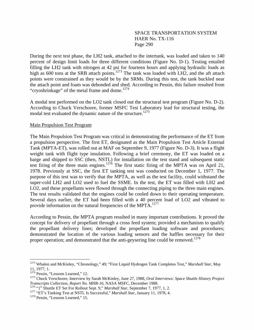
During the next test phase, the LH2 tank, attached to the intertank, was loaded and taken to 140 percent of design limit loads for three different conditions (Figure No. D-1). Testing entailed filling the LH2 tank with nitrogen at 42 psi for fourteen hours and applying hydraulic loads as high as 600 tons at the SRB attach points.1273 The tank was loaded with LH2, and the aft attach points were constrained as they would be by the SRMs. During this test, the tank buckled near the attach point and foam was debonded and shed. According to Pessin, this failure resulted from “cryoshrinkage” of the metal frame and dome.1274 A modal test performed on the LO2 tank closed out the structural test program (Figure No. D-2). According to Chuck Verschoore, former MSFC Test Laboratory lead for structural testing, the modal test evaluated the dynamic nature of the structure.1275 Main Propulsion Test Program The Main Propulsion Test Program was critical in demonstrating the performance of the ET from a propulsion perspective. The first ET, designated as the Main Propulsion Test Article External Tank (MPTA-ET), was rolled out at MAF on September 9, 1977 (Figure No. D-3). It was a flight weight tank with flight type insulation. Following a brief ceremony, the ET was loaded on a barge and shipped to SSC (then, NSTL) for installation on the test stand and subsequent static test firing of the three main engines.1276 The first static firing of the MPTA was on April 21, 1978. Previously at SSC, the first ET tanking test was conducted on December 1, 1977. The purpose of this test was to verify that the MPTA, as well as the test facility, could withstand the super-cold LH2 and LO2 used to fuel the SSME. In the test, the ET was filled with LH2 and LO2, and these propellants were flowed through the connecting piping to the three main engines. The test results validated that the engines could be cooled down to their operating temperature. Several days earlier, the ET had been filled with a 40 percent load of LO2 and vibrated to provide information on the natural frequencies of the MPTA.1277 According to Pessin, the MPTA program resulted in many important contributions. It proved the concept for delivery of propellant through a cross feed system; provided a mechanism to qualify the propellant delivery lines; developed the propellant loading software and procedures; demonstrated the location of the various loading sensors and the baffles necessary for their proper operation; and demonstrated that the anti-geysering line could be removed.1278
1273 Whalen and McKinley, “Chronology,” 49; “First Liquid Hydrogen Tank Completes Test,” Marshall Star, May 11, 1977, 1. 1274 Pessin, “Lessons Learned,” 12. 1275 Chuck Verschoore, Interview by Sarah McKinley, June 27, 1988, Oral Interviews: Space Shuttle History Project Transcripts Collection, Report No. MHR-16, NASA MSFC, December 1988. 1276 “1st Shuttle ET Set For Rollout Sept. 9,” Marshall Star, September 7, 1977, 1, 2. 1277 “ET’s Tanking Test at NSTL Is Successful,” Marshall Star, January 11, 1978, 4. 1278 Pessin, “Lessons Learned,” 15.
SPACE TRANSPORTATION SYSTEM HAER No. TX-116 Page 291
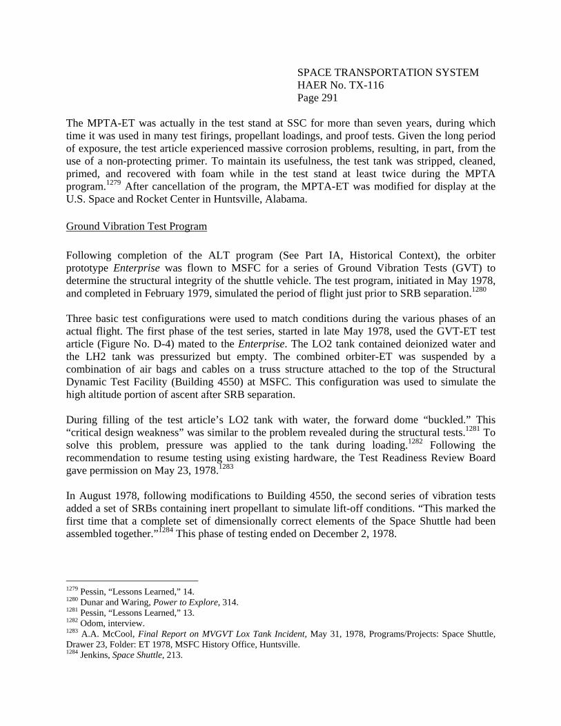
The MPTA-ET was actually in the test stand at SSC for more than seven years, during which time it was used in many test firings, propellant loadings, and proof tests. Given the long period of exposure, the test article experienced massive corrosion problems, resulting, in part, from the use of a non-protecting primer. To maintain its usefulness, the test tank was stripped, cleaned, primed, and recovered with foam while in the test stand at least twice during the MPTA program.1279 After cancellation of the program, the MPTA-ET was modified for display at the U.S. Space and Rocket Center in Huntsville, Alabama. Ground Vibration Test Program Following completion of the ALT program (See Part IA, Historical Context), the orbiter prototype Enterprise was flown to MSFC for a series of Ground Vibration Tests (GVT) to determine the structural integrity of the shuttle vehicle. The test program, initiated in May 1978, and completed in February 1979, simulated the period of flight just prior to SRB separation.1280 Three basic test configurations were used to match conditions during the various phases of an actual flight. The first phase of the test series, started in late May 1978, used the GVT-ET test article (Figure No. D-4) mated to the Enterprise. The LO2 tank contained deionized water and the LH2 tank was pressurized but empty. The combined orbiter-ET was suspended by a combination of air bags and cables on a truss structure attached to the top of the Structural Dynamic Test Facility (Building 4550) at MSFC. This configuration was used to simulate the high altitude portion of ascent after SRB separation. During filling of the test article’s LO2 tank with water, the forward dome “buckled.” This “critical design weakness” was similar to the problem revealed during the structural tests.1281 To solve this problem, pressure was applied to the tank during loading.1282 Following the recommendation to resume testing using existing hardware, the Test Readiness Review Board gave permission on May 23, 1978.1283 In August 1978, following modifications to Building 4550, the second series of vibration tests added a set of SRBs containing inert propellant to simulate lift-off conditions. “This marked the first time that a complete set of dimensionally correct elements of the Space Shuttle had been assembled together.”1284 This phase of testing ended on December 2, 1978.
1279 Pessin, “Lessons Learned,” 14. 1280 Dunar and Waring, Power to Explore, 314. 1281 Pessin, “Lessons Learned,” 13. 1282 Odom, interview. 1283 A.A. McCool, Final Report on MVGVT Lox Tank Incident, May 31, 1978, Programs/Projects: Space Shuttle, Drawer 23, Folder: ET 1978, MSFC History Office, Huntsville. 1284 Jenkins, Space Shuttle, 213.
SPACE TRANSPORTATION SYSTEM HAER No. TX-116 Page 292
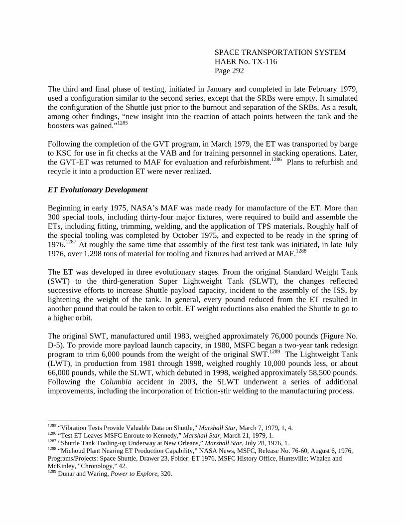
The third and final phase of testing, initiated in January and completed in late February 1979, used a configuration similar to the second series, except that the SRBs were empty. It simulated the configuration of the Shuttle just prior to the burnout and separation of the SRBs. As a result, among other findings, “new insight into the reaction of attach points between the tank and the boosters was gained.”1285 Following the completion of the GVT program, in March 1979, the ET was transported by barge to KSC for use in fit checks at the VAB and for training personnel in stacking operations. Later, the GVT-ET was returned to MAF for evaluation and refurbishment.1286 Plans to refurbish and recycle it into a production ET were never realized. ET Evolutionary Development Beginning in early 1975, NASA’s MAF was made ready for manufacture of the ET. More than 300 special tools, including thirty-four major fixtures, were required to build and assemble the ETs, including fitting, trimming, welding, and the application of TPS materials. Roughly half of the special tooling was completed by October 1975, and expected to be ready in the spring of 1976.1287 At roughly the same time that assembly of the first test tank was initiated, in late July 1976, over 1,298 tons of material for tooling and fixtures had arrived at MAF.1288 The ET was developed in three evolutionary stages. From the original Standard Weight Tank (SWT) to the third-generation Super Lightweight Tank (SLWT), the changes reflected successive efforts to increase Shuttle payload capacity, incident to the assembly of the ISS, by lightening the weight of the tank. In general, every pound reduced from the ET resulted in another pound that could be taken to orbit. ET weight reductions also enabled the Shuttle to go to a higher orbit. The original SWT, manufactured until 1983, weighed approximately 76,000 pounds (Figure No. D-5). To provide more payload launch capacity, in 1980, MSFC began a two-year tank redesign program to trim 6,000 pounds from the weight of the original SWT.1289 The Lightweight Tank (LWT), in production from 1981 through 1998, weighed roughly 10,000 pounds less, or about 66,000 pounds, while the SLWT, which debuted in 1998, weighed approximately 58,500 pounds. Following the Columbia accident in 2003, the SLWT underwent a series of additional improvements, including the incorporation of friction-stir welding to the manufacturing process.
1285 “Vibration Tests Provide Valuable Data on Shuttle,” Marshall Star, March 7, 1979, 1, 4. 1286 “Test ET Leaves MSFC Enroute to Kennedy,” Marshall Star, March 21, 1979, 1. 1287 “Shuttle Tank Tooling-up Underway at New Orleans,” Marshall Star, July 28, 1976, 1. 1288 “Michoud Plant Nearing ET Production Capability,” NASA News, MSFC, Release No. 76-60, August 6, 1976, Programs/Projects: Space Shuttle, Drawer 23, Folder: ET 1976, MSFC History Office, Huntsville; Whalen and McKinley, “Chronology,” 42. 1289 Dunar and Waring, Power to Explore, 320.
SPACE TRANSPORTATION SYSTEM HAER No. TX-116 Page 293
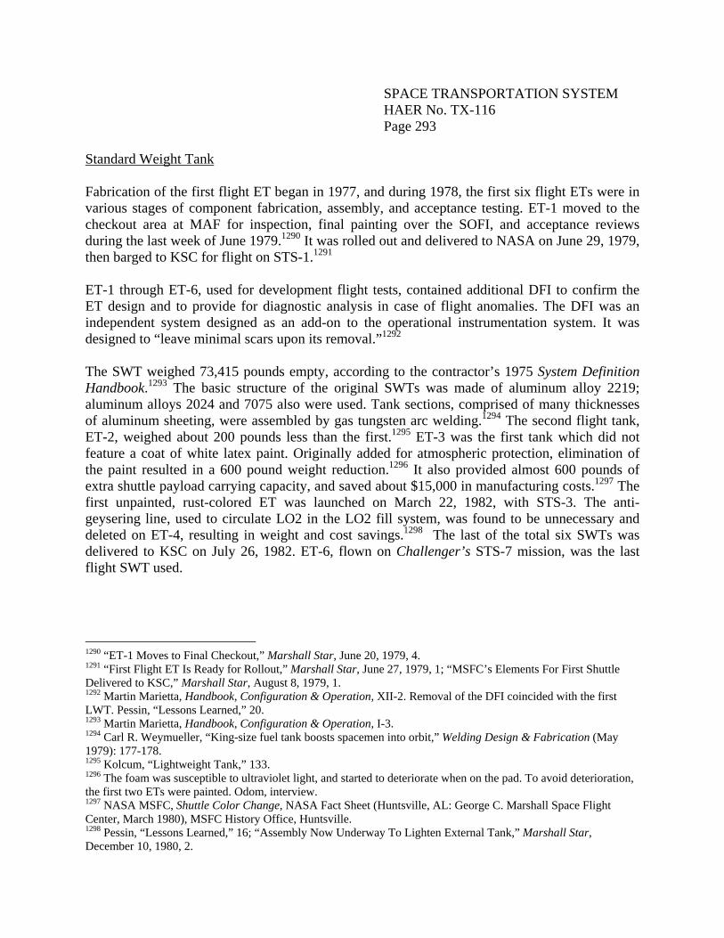
Standard Weight Tank Fabrication of the first flight ET began in 1977, and during 1978, the first six flight ETs were in various stages of component fabrication, assembly, and acceptance testing. ET-1 moved to the checkout area at MAF for inspection, final painting over the SOFI, and acceptance reviews during the last week of June 1979.1290 It was rolled out and delivered to NASA on June 29, 1979, then barged to KSC for flight on STS-1.1291 ET-1 through ET-6, used for development flight tests, contained additional DFI to confirm the ET design and to provide for diagnostic analysis in case of flight anomalies. The DFI was an independent system designed as an add-on to the operational instrumentation system. It was designed to “leave minimal scars upon its removal.”1292 The SWT weighed 73,415 pounds empty, according to the contractor’s 1975 System Definition Handbook.1293 The basic structure of the original SWTs was made of aluminum alloy 2219; aluminum alloys 2024 and 7075 also were used. Tank sections, comprised of many thicknesses of aluminum sheeting, were assembled by gas tungsten arc welding.1294 The second flight tank, ET-2, weighed about 200 pounds less than the first.1295 ET-3 was the first tank which did not feature a coat of white latex paint. Originally added for atmospheric protection, elimination of the paint resulted in a 600 pound weight reduction.1296 It also provided almost 600 pounds of extra shuttle payload carrying capacity, and saved about $15,000 in manufacturing costs.1297 The first unpainted, rust-colored ET was launched on March 22, 1982, with STS-3. The anti-geysering line, used to circulate LO2 in the LO2 fill system, was found to be unnecessary and deleted on ET-4, resulting in weight and cost savings.1298 The last of the total six SWTs was delivered to KSC on July 26, 1982. ET-6, flown on Challenger’s STS-7 mission, was the last flight SWT used.
1290 “ET-1 Moves to Final Checkout,” Marshall Star, June 20, 1979, 4. 1291 “First Flight ET Is Ready for Rollout,” Marshall Star, June 27, 1979, 1; “MSFC’s Elements For First Shuttle Delivered to KSC,” Marshall Star, August 8, 1979, 1. 1292 Martin Marietta, Handbook, Configuration & Operation, XII-2. Removal of the DFI coincided with the first LWT. Pessin, “Lessons Learned,” 20. 1293 Martin Marietta, Handbook, Configuration & Operation, I-3. 1294 Carl R. Weymueller, “King-size fuel tank boosts spacemen into orbit,” Welding Design & Fabrication (May 1979): 177-178. 1295 Kolcum, “Lightweight Tank,” 133. 1296 The foam was susceptible to ultraviolet light, and started to deteriorate when on the pad. To avoid deterioration, the first two ETs were painted. Odom, interview. 1297 NASA MSFC, Shuttle Color Change, NASA Fact Sheet (Huntsville, AL: George C. Marshall Space Flight Center, March 1980), MSFC History Office, Huntsville. 1298 Pessin, “Lessons Learned,” 16; “Assembly Now Underway To Lighten External Tank,” Marshall Star, December 10, 1980, 2.
SPACE TRANSPORTATION SYSTEM HAER No. TX-116 Page 294
Lightweight Tank Assembly of the first LWT, ET-81299 (Figure No. D-6), began in November 1980, with work on the aft dome of the LH2 tank. The tank arrived at KSC on September 8, 1982, and launched with STS-6 in April 1983. The eighty-fifth and final LWT was delivered to KSC on April 19, 1999, and flew on STS-99. The second generation ET (Figure No. D-7) weighed approximately 10,000 pounds less than the SWT.1300 To accomplish the weight reduction, the thickness of many of the aluminum skin panels was reduced. Selected stringers in the LH2 tank were eliminated, and fewer ring stiffeners were used in the barrel assemblies. Major frames in the LH2 tank were modified, and the slosh baffle in the LO2 tank was redesigned, resulting in a 600 pound reduction.1301 Dome caps, which were chemically milled on only one side, were now milled on both sides to reduce thickness and weight without reducing strength.1302 Beginning with ET-8, the GH2 pressurization line was relocated and the cable trays were reduced in size. This change allowed for the elimination of ablator from a section of the tank.1303 A titanium alloy which was stronger, lighter, and less expensive than the previous material, was used for the aft SRB attachments. Specifically, all 5A1-2.5 titanium alloy fittings were changed to 6A1-4V titanium alloy, and all 7075-T73 aluminum hardware was changed to 7050-T73 aluminum.1304 Like the SRBs, the original SWT contained a RSS capable of destroying the vehicle. The ET package consisted of linear-shaped charges on both the LO2 and LH2 tanks. Beginning with ET-80, the ET RSS was eliminated; the RSS was retained in the SRBs.1305 Elimination also enabled removal of the high temperature ablator, MA25S, from the cable tray segments where the linear-shaped charges were located, thus resulting in a small weight savings to the ET.1306 STS-78/ET-79 was the last to carry the ET RSS; STS-79/ET-82 was the first flight without it. According to Pessin, in order to enhance operations, two modifications were made which increased the ET weight. Approximately 200 pounds were added to the LO2 tank “to permit the topping and replenish flows to take place,” and over 400 pounds of aluminum were added to the LH2 tank aft domes in the form of circumferential ribs to stiffen the gores.1307 New welding techniques made LWT production more labor and cost efficient. Beginning in 1984, MSFC adopted Variable Polarity Plasma Arc welding. This method required less preweld
1299 Martin Marietta did not assign the number ET-7 since the tank was never completed. 1300 The weight savings from deleting the anti-geysering line and the white paint, both effected during SWT production, as well as the removal of DFI, were “booked” to the LWT reduction. Pessin, “Lessons Learned,” 20. 1301 Martin Marietta, “First Lightweight Propellant Tank to Fly on Shuttle Tomorrow,” n.d., Sweetsir Collection, STS-6C, Folder 125, Kennedy Space Center Archives, Florida. 1302 Kolcum, “Lightweight Tank,” 133; Martin Marietta, “Propellant Tank.” 1303 Pessin, “Lessons Learned,” 16. 1304 Jenkins, Space Shuttle, 422. 1305 Jenkins, Space Shuttle, 434. 1306 Pessin, “Lessons Learned,” 25. 1307 Pessin, “Lessons Learned,” 12, 20.
SPACE TRANSPORTATION SYSTEM HAER No. TX-116 Page 295
cleaning and edge preparation, and also minimized weld defects. Plasma Arc welding became the baseline process until the SLWT tools came along.1308 Super Lightweight Tank The SLWT, introduced in 1998, weighed 7,500 pounds less than the previous LWT, and allowed the Space Shuttle to carry heavy components for assembly of the ISS (Figure No. D-8).1309 The primary difference between the LWT and the SLWT was a change in material; no changes were made to the basic components. Aluminum alloy 2219 was replaced with aluminum-lithium (Al-Li) alloy 2195 in most of the major structures. This alloy was part of the Weldalite family developed and patented by Lockheed Martin Laboratories in Baltimore, Maryland. Al-Li alloy 2195 is composed of 1 percent lithium, 4 percent copper, 0.4 percent silver, 0.4 percent magnesium, and 94.2 percent aluminum. It is 30 percent stronger and 5 percent less dense than the original 2219 aluminum alloy.1310 Pre-production laboratory tests showed that Al-Li alloy 2195 could be welded, and could withstand a temperature of minus 423 degrees F, the temperature at which LH2 is stored. Originally, Reynolds Metals in Chicago, Illinois, provided the Al-Li material for SLWT production. After the company was sold to Alcan, located in Ravenswood, West Virginia, Alcan became the supplier.1311 While this aluminum-lithium alloy had superior qualities, NASA and Lockheed Martin engineers experienced many difficulties as they learned to form, weld and repair this new material.1312 As Pessin noted, “we were starting a program with a squeezed schedule, one on which the whole reputation of NASA was riding, and we could not make the material and could not make the repairs in it.”1313 Weld repairs were a significant challenge for production of the SLWTs using the new Al-Li alloy 2195. In the LH2 tank, the Al-Li 2195 replaced aluminum alloy 2219 in the dome cap and eleven of the twelve gore panels; the major ring frame outer chord at Station 1129;1314 the barrel panels; the ring frames; and the forward dome gore panels. Material replacement in the LO2 tank included the aft dome cap and gore panels; the Station 852 outer chord; the forward and aft ogive gores; the barrel panels; and the Station 745 T-ring outer chord.1315 The LH2 aft dome gore was left as 2219 aluminum “to eliminate the need to develop the weld processes in aluminum lithium.1316
1308 Pessin, “Lessons Learned,” 22; Dunar and Waring, Power to Explore, 321. 1309 Lockheed Martin Corporation, “External Tank,” 2010, http://www.lockheedmartin.com/ssc/ michoud/ExternalTank/index.html; NASA MSFC, “Super Lightweight External Tank,” April 2005, http://www.nasa.gov/centers/marshall/pdf/113020main_shuttle _lightweight.pdf. 1310 Lockheed Martin, “External Tank;” NASA MSFC, “Super Lightweight External Tank.” 1311 Lockheed Martin Space Systems Company, “Space Shuttle Super Lightweight External Tank,” July 2010, http://www.lockheedmartin.com/data/assets/9166.pdf. 1312 Pessin, “Lessons Learned,” 28-30. 1313 Pessin, “Lessons Learned,” 31. 1314 See page 314 for a definition of “station.” 1315 R.S. Ryan, “A History of Aerospace Problems, Their Solutions, Their Lessons,” NASA Technical Paper 3653 (Huntsville, AL: MSFC History Office, September 1996), 112, 114. 1316 Pessin, “Lessons Learned,” 36.
SPACE TRANSPORTATION SYSTEM HAER No. TX-116 Page 296
Many of the mechanically fastened materials in the intertank, skins, stringers, and doublers were changed to Alcoa’s Al-Li 2090. Compared with the LWT, membrane thickness in the SLWT was resized in the LH2 tank dome cap and eleven gores, as well as the LH2 aft dome cap, gore panels, and barrel panels.1317 Many SLWT weld lands were increased in thickness by up to 0.35” to allow more margin for potential weld repairs. These robust weld lands included the longeron to barrel panel; barrel panel to barrel panel on Barrel No. 2 forward of the longerons; Frame 1623 and 1377 chord to chord aluminum 2195 welds; LH2 forward and aft dome gore to dome gore; LH2 forward and aft chord to gore; LH2 aft dome cap to dome body; and LH2 aft manhole and siphon plate.1318 In addition to the change in material, the SLWT’s structural design was improved. The SLWT featured a new orthogonal waffle grid design (called an orthogrid) to improve strength and stability. The new design replaced the LH2 tank T-stiffeners, and provided almost half of the SLWT weight savings. Weight savings also were made by machining off the excess foam on the entire intertank, resulting in a reduction of approximately 270 pounds of foam. Additionally, the thickness of the foam applied to the LH2 barrel section was controlled, saving about 55 pounds on the SLWT. 1319 Seven Z frames were eliminated in the LH2 tank barrel panels, and one baffle tray was removed from the LO2 tank.1320 The first SLWT, ET-96, arrived at KSC in February 1998. It flew with Discovery’s STS-91 mission, launched on June 2, 1998. ET-138, the last production SLWT, flew on STS-135 (July 8, 2011), the final mission of the SSP (Figure No. D-9). Prior to the STS-91 mission, between February and September 1996, a special Aluminum Lithium Test Article (ALTA) was used in a series of SLWT certification and capability tests at MSFC. The test article consisted of a single ET barrel with a forward LH2 dome and an aft LO2 dome. It measured 40’ long and 27’ in diameter.1321 Reynolds Metals Company cast the Al-Li 2195 ingots for the ALTA.1322 To verify the structural integrity of the LH2 tank’s new orthogonal waffle-like design and new aluminum lithium material, the test article was exposed to loads and pressures to simulate the conditions while at the pad, at liftoff, and when the SRBs separated from the shuttle. Following completion of the certification test series, the test article underwent a series of capability tests, including testing the article to the point of failure. While
1317 Ryan, “Aerospace Problems,” 112, 114. 1318 Lockheed Martin, Space Shuttle External Tank, System Definition Handbook SLWT, Layout Drawings Volume II (New Orleans, LA: Lockheed Martin, December 1997), III-5, MSFC History Office, Huntsville. 1319 Pessin, “Lessons Learned,” 32, 36, 37. 1320 Ryan, “Aerospace Problems,” 112, 114. 1321 Pessin, “Lessons Learned,” 34; Ed Campion and June Malone, “Super Lightweight External Tank Certification Testing to Begin,” February 1996, http://findarticles.com/p/articles/mi_pasa/is_199602/ai_901012153. 1322 Martin Marietta Manned Space Systems, “Tank weld assembly team prepares for test schedule,” Mission Success Bulletin (Huntsville, AL: MSFC History Office, August 23, 1994), 2.
SPACE TRANSPORTATION SYSTEM HAER No. TX-116 Page 297
not required to certify the tank for flight, these tests provided valuable data about the SLWT’s structural capability.1323 A “second generation” of SLWTs used a lighter, stronger alloy (Al-Li 2297) in the intertank thrust panels, resulting in a significant weight savings. Following on this change, although adding weight back, all of the dome gores and ogive gores were converted back to 2219 aluminum, which was easier to weld, and which drastically reduced repairs.1324 The final enhancement to the SLWT was the introduction of friction stir welding. This process was selected by ET project managers because it produced stronger welds that were easier to make on the lighter-weight Al-Li 2195 alloy. Friction stir welding also had “significantly fewer process elements to control,” compared with fusion welding, used in the manufacture of the earlier tanks.1325 Additionally, the process variables were highly repeatable, and minimized the risk of weld defects.1326 NASA and Lockheed Martin initially demonstrated the effectiveness of the friction stir welding process in 1998 using a 27.5’-diameter simulated LH2 tank with six barrel panels. Two subsequent special studies were completed between 1999 and 2001, and friction stir welding was implemented into production in 2001. Eight longitudinal weld joints on the LH2 barrel and four longitudinal welds on the LO2 barrel were welded using this process, totaling approximately 700’ of weldments on each ET.1327 ET-132 was the first ET to fly (STS-132, launched on August 28, 2009) with a friction stir weld.1328 It featured longitudinal friction stir welds on two of the LH2 tank barrels. ET-133, flown with Atlantis in November 2009, also featured friction stir welds on two barrels. ET-134, the 130th tank Lockheed Martin fabricated for the SSP, and which flew on Endeavour’s STS-134 mission, was the first flight ET to feature longitudinal friction stir welds on all four LH2 tank barrels and the single LO2 tank barrel.1329 ET-134 also featured lighter aluminum lithium material on the intertank thrust panels and on the LO2 tank aft ogive panels.1330
1323 Michael Braukus and June Malone, “Shuttle Super Lightweight Fuel Tank Completes Test Series,” July 1996, http://findarticles.com/p/articles/mi_pasa/is_199607/ai_238988282. 1324 Pessin, “Lessons Learned,” 37. 1325 NASA MSFC, “Friction Stir Welding,” 2001, http://www.nasa.gov/centers/ Marshall/ pdf/104835main_friction.pdf. 1326 Jeff Ding, et al., “A Decade of Friction Stir Welding R&D At NASA’s Marshall Space Flight Center and a Glance into the Future,” NASA MSFC, no date, http://ntrs.nasa.gov/archive/nasa/casi.ntrs.nasa.gov/ 20080009619_2008009118.pdf. 1327 Ding, et al., “Friction Stir Welding.” Each ET has approximately one-half mile of total weldments. 1328 Lockheed Martin, “Flight Info.” 1329 “External Tank Flies with Improved Welds.” ET-134 also debuted improved intertank, thrust panels constructed of Al-Li 2297, a lighter material, which replaced AL-Li 2219, used on all previous intertanks. 1330 Lockheed Martin, “Flight Info,” 97. Aluminum 2219 was substituted with Aluminum 2297, which has lower density (7 percent) with similar mechanical properties. This change resulted in an approximate 226 pound reduction in structural weight. Chris Bergin, “STS-132 FRR approves May 14 launch date – External Tank Boost,” May 5, 2010, http://www.nasaspaceflight.com/2010/05/sts-132-frr-approve-may-14-external-tank-boost/.
SPACE TRANSPORTATION SYSTEM HAER No. TX-116 Page 298
Thermal Protection System Changes “Of all the changes other than the weight reduction – which is by design,” James Odom stated, “the changes to the TPS was [sic] probably the most difficult and probably cost us the most money.”1331 Every time a component in a foam was changed, the foam needed to be recertified. Porter Bridwell, former ET Program Manager, agreed that the TPS materials represented a major change to the tank.1332 Compliance with new federal environmental regulations was a key driver of change in NASA’s use of ET TPS materials, particularly affecting the use of certain types of insulating foam. On September 16, 1987, leaders from the U.S. and other world nations signed the “Montreal Protocol on Substances that Deplete the Ozone Layer.” Under this international environmental treaty, Class I ozone-depleting compounds, such as chlorofluorocarbons (CFCs), were to be phased out of production by the end of 1995. The Environmental Protection Agency (EPA) set a date of January 1, 1996, for the total phase out of CFCs.1333 CFC-11, a Freon-based blowing agent, was a major constituent in foams used for the ET, including those in the CPR, NCFI, BX, and PDL families.1334 Production of this compound after 1995 was allowed only by special exemption, and with Montreal Protocol approval. After extensive testing, NASA’s ET Project proposed to replace CFC-11 with the hydrochlorofluorocarbon (HCFC) HCFC-141b for applying the NCFI foams.1335 At the same time, the EPA allowed NASA to continue use of stockpiled supplies of CFC-11 until HCFC-141b was certified for use on the Space Shuttle and phased in. Provided with several years of advance notice, according to Pessin, NASA and Lockheed Martin worked to develop and qualify a second source for the sidewall foam. When this foam was reformulated with the HCFC-141b blowing agent, it was able to meet all known ET requirements.1336 The new foam, NCFI 24-124 containing HCFC-141b, was certified for flight, and phased in over three tanks. It was first used on the LH2 tank aft dome of ET-82 which flew with STS-79 in 1996. In 1997, beginning with ET-88/STS-86, the HCFC-141b-containing foam was applied on the tank’s acreage.1337 In 1999, the EPA expanded its ban on ozone-depleting substances. As a result, BX-250, a polyurethane foam containing CFC-11, was banned. NASA’s request for an exception was
1331 Odom, interview. 1332 Porter Bridwell, interview by Jessie Whalen and Sarah McKinley, December 18, 1987, Oral Interviews: Space Shuttle History Project Transcripts Collection, NASA MSFC, December 1988, 37. 1333 U.S. EPA, “Montreal Protocol on Substances that Deplete the Ozone Layer,” no date, http://www.epa.gov/ozone/downloads/MP20_FactSheet.pdf. 1334 CPR denotes Chemical Products Research (which was bought by Upjohn, which, in turn, was purchased by Dow); NCFI is the North Carolina Foam Industries; PDL denotes Product Development Laboratory. 1335 The HCFCs were later targeted for phase-out by the EPA. U.S. EPA, “Montreal Protocol.” 1336 Pessin, “Lessons Learned,” 26. 1337 NASA MSFC, External Tank Thermal Protection System, NASA Facts, (Huntsville, AL: Marshall Space Flight Center, April 2005), http://www.nasa.gov/centers/marshall/pdf/114022main_TPS_FS.pdf.
SPACE TRANSPORTATION SYSTEM HAER No. TX-116 Page 299
granted by the EPA, and subsequently, NASA developed BX-265 foam, applied with HCFC-141b, as a replacement. In December 2001, BX-265 first flew as a replacement of BX-250. However, tanks already insulated with BX-250 continued to be flown as BX-265 was implemented through the manufacturing process.1338 Post-Columbia Modifications to the ET Historical Background On January 22 and 24, 1981, the LH2 and LO2 tanks of ET-1 were loaded with 1.6 million pounds of propellants in preparation for STS-1. A few days later, The Huntsville Times reported that engineers at KSC were inspecting damaged foam insulation on Columbia’s ET. Two sections of foam insulation had come loose in the area of the bipod that attached the orbiter’s nose to the tank. The cause was believed to be related to the slight shrinkage of the aluminum tank as the supercold LH2 and LO2 were loaded.1339 Repairs began on March 8, and Columbia was launched on April 12, 1981, marking the beginning of the Space Shuttle flight program.1340 While the STS-1 mission was a success, about 300 orbiter tiles needed replacement due to damage from ET foam impacts. The foam “liberation” on the Shuttle’s first flight ET foreshadowed the events ahead, culminating with the Columbia accident, when foam debris struck the orbiter’s wing leading edge, resulting in the loss of the STS-107 shuttle crew and vehicle. As underscored in the report of the CAIB, “the shedding of External Tank foam – the physical cause of the Columbia accident – had a long history. Damage caused by debris has occurred on every Space Shuttle flight, and most missions have had insulating foam shed during ascent.”1341 The CAIB report also noted that of the seventy-nine missions for which photographic imagery was available, there was evidence of foam shedding for sixty-five of the missions.1342 In the aftermath of the tragedy, the CAIB recommended that NASA initiate an aggressive program to eliminate all ET TPS debris-shedding at the source (Figure No. D-10). In response, NASA developed and implemented a three-phase approach. Phase 1, implemented prior to RTF, focused on already built tanks. Tests and analyses were conducted to understand the root causes of foam shedding. As a result, structural changes were made to the LH2 tank ice/frost ramps; the LO2 feedline brackets; the forward ET/orbiter attach fitting, called the bipod; and the LO2 tank feedline bellows.
1338 NASA MSFC, Thermal Protection System. 1339 Whalen and McKinley, “Chronology,” 79. 1340 Whalen and McKinley, “Chronology,” 81. 1341 CAIB, Report, Volume I, 121. 1342 CAIB, Report, Volume I, 122.
SPACE TRANSPORTATION SYSTEM HAER No. TX-116 Page 300
In addition to these modifications, enhanced process controls were implemented to improve safety and to reduce instances of liberated foam. These included test panels, video review of spray applications, increased inspections, and more refined engineering requirements. Beginning with the first RTF mission, STS-114, an enhanced finishing procedure was implemented to improve foam application to the stringers, or intertank ribbing, and to the upper and lower area of the LH2 intertank flange.1343 Phase 2 efforts, not considered mandatory for RTF, focused on continuous improvement, such as practical debris elimination enhancements that could be incorporated into production. Phase 3 encompassed long-term development activities that would eliminate TPS foam on the vehicle. The Phase 3 changes were never implemented, due to the retirement of the SSP.1344 NASA conducted two RTF missions to validate the effectiveness of the changes made to meet the recommendations of the CAIB: STS-114/ET-121 in July 2005, and STS-121/ET-119 in July 2006. ET-120 was the first tank to be modified with new safety improvements mandated by the CAIB. It shipped from MAF on December 31, 2004, and was scheduled to fly with Discovery on the first RTF mission, STS-114, originally set to launch on May 22, 2005.1345 However, when the results of a tanking test indicated ice build up on the LO2 feedline bellows, a problem that could not be addressed on the pad, Discovery was returned to the VAB where ET-120 was swapped out with ET-121. On July 26, 2005, at 127 seconds into the flight, a piece of foam, measuring about 36” long and 11” wide, detached from the tank. The location of the foam loss was approximately 15’ below the flange that joined the intertank to the LH2 tank, or about 20’ from the top of the LH2 Protuberance Air Load (PAL) ramp. Thus, despite significant modifications to reduce the possibility of foam loss, STS-114 experienced foam liberation during ascent; the foam did not impact the orbiter. After STS-114, in October 2005, NASA shipped both ET-119 and ET-120 back to MAF for destructive evaluation and non-destructive evaluation (NDE) to determine the most probable cause of the foam losses, and “to redesign, test, and eliminate those causes.”1346 Subsequently, in October 2005, ET-120 was used as a dissection test article during an investigation at MAF to better understand the foam loss on the PAL and ice/frost ramps during the STS-114 mission.1347 Dissections revealed TPS cracking at the LH2 PAL ramp and LH2 ice/frost ramp locations of ET-120. Unlike ET-120, which had been through two tanking and thermal cycles, ET-119, which
1343 NASA MSFC, Space Shuttle External Tank ET-128, STS-124, NASA Facts, (Huntsville, AL: George C. Marshall Space Flight Center, 2008), http://www.nasa.gov/centers/marshall/pdf/228641main_8-368946_%282%29.pdf. 1344 NASA, NASA’s Implementation Plan, 1-4. 1345 NASA, STS-120, Harmony: A Global Gateway (Washington, DC: NASA, October 2007), 68, http://www.nasa.gov/pdf/ 192725main_STS-120_Shuttle_Press_Kit.pdf. 1346 NASA, Implementation Plan, xiii. 1347 Following its use in the foam loss investigation, ET-120 was repaired to return it to flight status. Repair work began in October 2006, and ET-120 supported the launch on need effort for Endeavour’s STS-118 mission, launched in August 2007. Later, ET-120 flew with Discovery’s STS-120 mission, launched on October 23, 2007.
SPACE TRANSPORTATION SYSTEM HAER No. TX-116 Page 301
had not been through these cycles, did not have cracks in the LH2 tank’s PAL ramp foam. The cracks most likely occurred during thermal cycling, it was concluded, “and similar cracks were the most likely cause of the foam loss on STS-114/ET-121.1348 PAL ramps (Figure No. D-11) were manually sprayed wedge-shaped layers of foam. Originally, they were designed as a safety precaution to protect the pressurization lines and cable tray along the side of the ET from airflow during ascent. Prior to their elimination, each ET had two PAL ramps. One was located near the aft end of the LO2 tank, just above the intertank, and the other was below the intertank, along the upper end of the LH2 tank. Both ramps extended about 5’ into the intertank area. The LO2 PAL ramp was 13.7’ long and the LH2 PAL ramp was 36.6’ long. Prior to STS-114, PAL ramp foam loss had been observed on STS-4/ET-4 and STS-7/ET-6. The likely causes of these losses were believed to be repairs and cryo-pumping (air ingestion) into the ablator panels under and adjacent to the PAL ramps.1349 Following nearly three years of studies and testing, NASA determined that eliminating the PAL ramps was the best means of reducing the risk of foam debris. Removal of the PAL ramps reduced the weight of the ET foam by about 37 pounds.1350 ET-119, flown on the second RTF mission, STS-121, which launched on July 4, 2006, was the first to fly without PAL ramps.1351 The tank featured small, foam ice/frost ramp extensions, which had been added to the ice/frost ramp locations where the PAL ramps were removed. A total of nine extensions were added, six on the LH2 tank and three on the LO2 tank. Each weighed 0.10 pounds.1352 This mission demonstrated that removal of the PAL ramp was successful in reducing the debris risk. As a result, the PAL ramps were removed from all future tanks. ET-128, launched with STS-124 on May 31, 2008, was the first tank to fly with all RTF improvements incorporated during production instead of being added after manufacturing was complete.1353 Description of Structural Changes Beginning with RTF, several elements of the ET were the focus of redesign and structural modifications which generally aimed at mitigating foam loss. These key areas included the ice/frost ramps, the LO2 feedline brackets, the LO2 feedline bellows, the LH2 tank/intertank flange region, the forward bipod fitting, and the +Z aerovent. In addition to these changes, a new observation camera system was implemented, in accordance with the CAIB recommendations. A summary of these modifications follows.
1348 NASA, Implementation Plan, 1-4. 1349 NASA, Implementation Plan, 1-2. 1350 NASA MSFC, Return to Flight External Tank, ET-119, NASA Facts, (Huntsville, AL: George C. Marshall Space Flight Center, June 2005), http://www.nasa.gov/centers/marshall/pdf/150034main_Shuttle_ET-119_FS.pdf. 1351 Lockheed Martin, “Flight Info,” 89; NASA MSFC, ET-119; NASA, STS-120, 68. 1352 NASA MSFC, Preparing the External Tank, ET-118, NASA Facts (Huntsville, AL: George C. Marshall Space Flight Center, August 2006), http://www.nasa.gov/centers/marshall/pdf/155290main_shuttle_et118_fs.pdf. 1353 NASA MSFC, Tank ET-128.
SPACE TRANSPORTATION SYSTEM HAER No. TX-116 Page 302
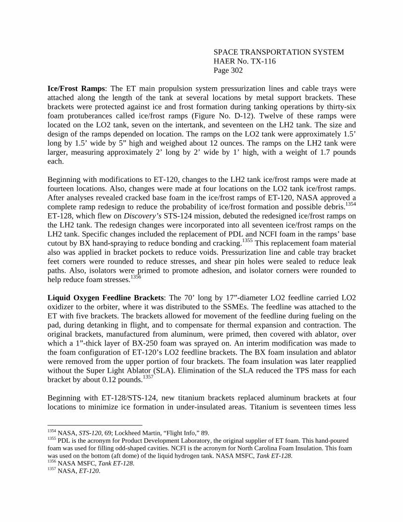
Ice/Frost Ramps: The ET main propulsion system pressurization lines and cable trays were attached along the length of the tank at several locations by metal support brackets. These brackets were protected against ice and frost formation during tanking operations by thirty-six foam protuberances called ice/frost ramps (Figure No. D-12). Twelve of these ramps were located on the LO2 tank, seven on the intertank, and seventeen on the LH2 tank. The size and design of the ramps depended on location. The ramps on the LO2 tank were approximately 1.5’ long by 1.5’ wide by 5” high and weighed about 12 ounces. The ramps on the LH2 tank were larger, measuring approximately 2’ long by 2’ wide by 1’ high, with a weight of 1.7 pounds each. Beginning with modifications to ET-120, changes to the LH2 tank ice/frost ramps were made at fourteen locations. Also, changes were made at four locations on the LO2 tank ice/frost ramps. After analyses revealed cracked base foam in the ice/frost ramps of ET-120, NASA approved a complete ramp redesign to reduce the probability of ice/frost formation and possible debris.1354 ET-128, which flew on Discovery’s STS-124 mission, debuted the redesigned ice/frost ramps on the LH2 tank. The redesign changes were incorporated into all seventeen ice/frost ramps on the LH2 tank. Specific changes included the replacement of PDL and NCFI foam in the ramps’ base cutout by BX hand-spraying to reduce bonding and cracking.1355 This replacement foam material also was applied in bracket pockets to reduce voids. Pressurization line and cable tray bracket feet corners were rounded to reduce stresses, and shear pin holes were sealed to reduce leak paths. Also, isolators were primed to promote adhesion, and isolator corners were rounded to help reduce foam stresses.1356 Liquid Oxygen Feedline Brackets: The 70’ long by 17”-diameter LO2 feedline carried LO2 oxidizer to the orbiter, where it was distributed to the SSMEs. The feedline was attached to the ET with five brackets. The brackets allowed for movement of the feedline during fueling on the pad, during detanking in flight, and to compensate for thermal expansion and contraction. The original brackets, manufactured from aluminum, were primed, then covered with ablator, over which a 1”-thick layer of BX-250 foam was sprayed on. An interim modification was made to the foam configuration of ET-120’s LO2 feedline brackets. The BX foam insulation and ablator were removed from the upper portion of four brackets. The foam insulation was later reapplied without the Super Light Ablator (SLA). Elimination of the SLA reduced the TPS mass for each bracket by about 0.12 pounds.1357 Beginning with ET-128/STS-124, new titanium brackets replaced aluminum brackets at four locations to minimize ice formation in under-insulated areas. Titanium is seventeen times less
1354 NASA, STS-120, 69; Lockheed Martin, “Flight Info,” 89. 1355 PDL is the acronym for Product Development Laboratory, the original supplier of ET foam. This hand-poured foam was used for filling odd-shaped cavities. NCFI is the acronym for North Carolina Foam Insulation. This foam was used on the bottom (aft dome) of the liquid hydrogen tank. NASA MSFC, Tank ET-128. 1356 NASA MSFC, Tank ET-128. 1357 NASA, ET-120.
SPACE TRANSPORTATION SYSTEM HAER No. TX-116 Page 303
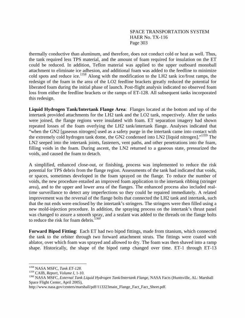
thermally conductive than aluminum, and therefore, does not conduct cold or heat as well. Thus, the tank required less TPS material, and the amount of foam required for insulation on the ET could be reduced. In addition, Teflon material was applied to the upper outboard monoball attachment to eliminate ice adhesion, and additional foam was added to the feedline to minimize cold spots and reduce ice.1358 Along with the modification to the LH2 tank ice/frost ramps, the redesign of the foam in the area of the LO2 feedline brackets greatly reduced the potential for liberated foam during the initial phase of launch. Post-flight analysis indicated no observed foam loss from either the feedline brackets or the ramps of ET-128. All subsequent tanks incorporated this redesign. Liquid Hydrogen Tank/Intertank Flange Area: Flanges located at the bottom and top of the intertank provided attachments for the LH2 tank and the LO2 tank, respectively. After the tanks were joined, the flange regions were insulated with foam. ET separation imagery had shown repeated losses of the foam overlying the LH2 tank/intertank flange. Analyses indicated that “when the GN2 [gaseous nitrogen] used as a safety purge in the intertank came into contact with the extremely cold hydrogen tank dome, the GN2 condensed into LN2 [liquid nitrogen].”1359 The LN2 seeped into the intertank joints, fasteners, vent paths, and other penetrations into the foam, filling voids in the foam. During ascent, the LN2 returned to a gaseous state, pressurized the voids, and caused the foam to detach. A simplified, enhanced close-out, or finishing, process was implemented to reduce the risk potential for TPS debris from the flange region. Assessments of the tank had indicated that voids, or spaces, sometimes developed in the foam sprayed on the flange. To reduce the number of voids, the new procedure entailed an improved foam application to the intertank ribbing (stringer area), and to the upper and lower area of the flanges. The enhanced process also included real-time surveillance to detect any imperfections so they could be repaired immediately. A related improvement was the reversal of the flange bolts that connected the LH2 tank and intertank, such that the nut ends were enclosed by the intertank’s stringers. The stringers were then filled using a new mold-injection procedure. In addition, the spraying process on the intertank’s thrust panel was changed to assure a smooth spray, and a sealant was added to the threads on the flange bolts to reduce the risk for foam debris.1360 Forward Bipod Fitting: Each ET had two bipod fittings, made from titanium, which connected the tank to the orbiter through two forward attachment struts. The fittings were coated with ablator, over which foam was sprayed and allowed to dry. The foam was then shaved into a ramp shape. Historically, the shape of the bipod ramp changed over time. ET-1 through ET-13
1358 NASA MSFC, Tank ET-128. 1359 CAIB, Report, Volume I, 1-10. 1360 NASA MSFC, External Tank Liquid Hydrogen Tank/Intertank Flange, NASA Facts (Huntsville, AL: Marshall Space Flight Center, April 2005), http://www.nasa.gov/centers/marshall/pdf/113323main_Flange_Fact_Fact_Sheet.pdf.
SPACE TRANSPORTATION SYSTEM HAER No. TX-116 Page 304
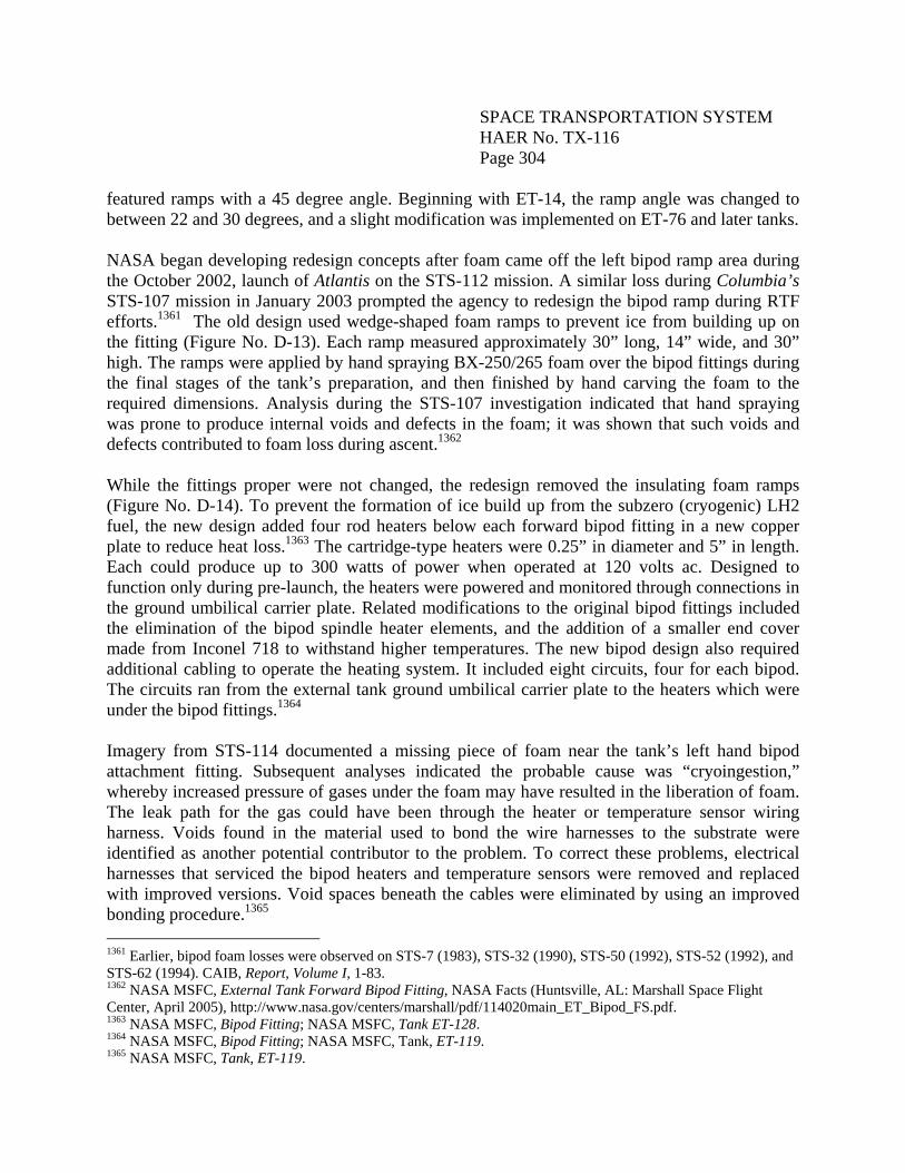
featured ramps with a 45 degree angle. Beginning with ET-14, the ramp angle was changed to between 22 and 30 degrees, and a slight modification was implemented on ET-76 and later tanks. NASA began developing redesign concepts after foam came off the left bipod ramp area during the October 2002, launch of Atlantis on the STS-112 mission. A similar loss during Columbia’s STS-107 mission in January 2003 prompted the agency to redesign the bipod ramp during RTF efforts.1361 The old design used wedge-shaped foam ramps to prevent ice from building up on the fitting (Figure No. D-13). Each ramp measured approximately 30” long, 14” wide, and 30” high. The ramps were applied by hand spraying BX-250/265 foam over the bipod fittings during the final stages of the tank’s preparation, and then finished by hand carving the foam to the required dimensions. Analysis during the STS-107 investigation indicated that hand spraying was prone to produce internal voids and defects in the foam; it was shown that such voids and defects contributed to foam loss during ascent.1362 While the fittings proper were not changed, the redesign removed the insulating foam ramps (Figure No. D-14). To prevent the formation of ice build up from the subzero (cryogenic) LH2 fuel, the new design added four rod heaters below each forward bipod fitting in a new copper plate to reduce heat loss.1363 The cartridge-type heaters were 0.25” in diameter and 5” in length. Each could produce up to 300 watts of power when operated at 120 volts ac. Designed to function only during pre-launch, the heaters were powered and monitored through connections in the ground umbilical carrier plate. Related modifications to the original bipod fittings included the elimination of the bipod spindle heater elements, and the addition of a smaller end cover made from Inconel 718 to withstand higher temperatures. The new bipod design also required additional cabling to operate the heating system. It included eight circuits, four for each bipod. The circuits ran from the external tank ground umbilical carrier plate to the heaters which were under the bipod fittings.1364 Imagery from STS-114 documented a missing piece of foam near the tank’s left hand bipod attachment fitting. Subsequent analyses indicated the probable cause was “cryoingestion,” whereby increased pressure of gases under the foam may have resulted in the liberation of foam. The leak path for the gas could have been through the heater or temperature sensor wiring harness. Voids found in the material used to bond the wire harnesses to the substrate were identified as another potential contributor to the problem. To correct these problems, electrical harnesses that serviced the bipod heaters and temperature sensors were removed and replaced with improved versions. Void spaces beneath the cables were eliminated by using an improved bonding procedure.1365 1361 Earlier, bipod foam losses were observed on STS-7 (1983), STS-32 (1990), STS-50 (1992), STS-52 (1992), and STS-62 (1994). CAIB, Report, Volume I, 1-83. 1362 NASA MSFC, External Tank Forward Bipod Fitting, NASA Facts (Huntsville, AL: Marshall Space Flight Center, April 2005), http://www.nasa.gov/centers/marshall/pdf/114020main_ET_Bipod_FS.pdf. 1363 NASA MSFC, Bipod Fitting; NASA MSFC, Tank ET-128. 1364 NASA MSFC, Bipod Fitting; NASA MSFC, Tank, ET-119. 1365 NASA MSFC, Tank, ET-119.
SPACE TRANSPORTATION SYSTEM HAER No. TX-116 Page 305
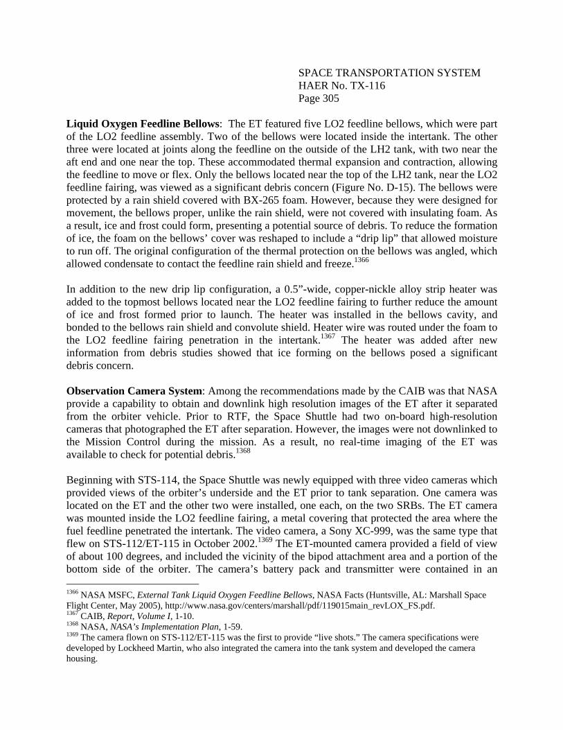
Liquid Oxygen Feedline Bellows: The ET featured five LO2 feedline bellows, which were part of the LO2 feedline assembly. Two of the bellows were located inside the intertank. The other three were located at joints along the feedline on the outside of the LH2 tank, with two near the aft end and one near the top. These accommodated thermal expansion and contraction, allowing the feedline to move or flex. Only the bellows located near the top of the LH2 tank, near the LO2 feedline fairing, was viewed as a significant debris concern (Figure No. D-15). The bellows were protected by a rain shield covered with BX-265 foam. However, because they were designed for movement, the bellows proper, unlike the rain shield, were not covered with insulating foam. As a result, ice and frost could form, presenting a potential source of debris. To reduce the formation of ice, the foam on the bellows’ cover was reshaped to include a “drip lip” that allowed moisture to run off. The original configuration of the thermal protection on the bellows was angled, which allowed condensate to contact the feedline rain shield and freeze.1366 In addition to the new drip lip configuration, a 0.5”-wide, copper-nickle alloy strip heater was added to the topmost bellows located near the LO2 feedline fairing to further reduce the amount of ice and frost formed prior to launch. The heater was installed in the bellows cavity, and bonded to the bellows rain shield and convolute shield. Heater wire was routed under the foam to the LO2 feedline fairing penetration in the intertank.1367 The heater was added after new information from debris studies showed that ice forming on the bellows posed a significant debris concern. Observation Camera System: Among the recommendations made by the CAIB was that NASA provide a capability to obtain and downlink high resolution images of the ET after it separated from the orbiter vehicle. Prior to RTF, the Space Shuttle had two on-board high-resolution cameras that photographed the ET after separation. However, the images were not downlinked to the Mission Control during the mission. As a result, no real-time imaging of the ET was available to check for potential debris.1368 Beginning with STS-114, the Space Shuttle was newly equipped with three video cameras which provided views of the orbiter’s underside and the ET prior to tank separation. One camera was located on the ET and the other two were installed, one each, on the two SRBs. The ET camera was mounted inside the LO2 feedline fairing, a metal covering that protected the area where the fuel feedline penetrated the intertank. The video camera, a Sony XC-999, was the same type that flew on STS-112/ET-115 in October 2002.1369 The ET-mounted camera provided a field of view of about 100 degrees, and included the vicinity of the bipod attachment area and a portion of the bottom side of the orbiter. The camera’s battery pack and transmitter were contained in an 1366 NASA MSFC, External Tank Liquid Oxygen Feedline Bellows, NASA Facts (Huntsville, AL: Marshall Space Flight Center, May 2005), http://www.nasa.gov/centers/marshall/pdf/119015main_revLOX_FS.pdf. 1367 CAIB, Report, Volume I, 1-10. 1368 NASA, NASA’s Implementation Plan, 1-59. 1369 The camera flown on STS-112/ET-115 was the first to provide “live shots.” The camera specifications were developed by Lockheed Martin, who also integrated the camera into the tank system and developed the camera housing.
SPACE TRANSPORTATION SYSTEM HAER No. TX-116 Page 306
electronics box mounted on top of the SRB crossbeam inside the ET. The camera also had two S-band antennas located on the opposite side of the tank from the orbiter. The complete camera system weighed thirty-two pounds. The camera system was activated about three minutes prior to launch, and operated for fifteen minutes following liftoff. The video was downlinked during flight to several NASA data receiving sites. Lockheed Martin Space Systems developed the camera specifications and camera housing, and integrated the camera into the ET system.1370 +Z Aerovent: The final post-Columbia modification, which debuted with ET-135/STS-131, was the removal of foam-over-foam around the +Z aerovent near the forward flange of the intertank. This change was implemented to reduce the potential for crack formation. The successful first flight of the +Z aerovent TPS redesign underscored the lessons learned from on-going investigations of foam loss events. Contamination on the intertank structure, prior to the application of foam, it had been observed, resulted in bond adhesion failures, which caused foam shedding during ascent. In response, changes in production procedures were implemented at MAF, which resulted in more effective substrate cleaning and TPS application on the intertank.1371 Other Challenges: Return to Flight to Final Mission ET foam debris shedding continued throughout the SSP, but diminished in frequency as the result of the redesign efforts. Reportedly, the last few flights were the “cleanest.” Other problems related to the ET challenged NASA up until the near close of the SSP. These included continued difficulties with the LH2 engine cutoff (ECO) sensors, as well as stringer cracks in the intertank. LH2 ECO Sensors Four ECO sensors were mounted on a single carrier plate approximately 4’ from the bottom of the LH2 tank (Figure No. D-16). Designed to activate in an emergency situation, they indicated when the ET was about to run out of propellant. In preparation for the STS-114 RTF mission, a tanking test on ET-120 resulted in an ECO sensor anomaly. The sensors indicated “wet” when there was no propellant in the tank. Because of another problem that could not be fixed at the pad, Discovery was rolled back to the VAB and the orbiter was mated to another stack, originally intended for the next mission, STS-121. Discovery was returned to the launch pad with its new stack about one month before the targeted launch. During pre-launch check-outs on the day of launch, the LH2 ECO sensor on the new tank falsely indicated “wet,” resulting in a launch scrub. As a result, NASA conducted a more thorough investigation of the anomaly. Discovery eventually launched successfully on July 26, 2005, and no false indicators were received from the LH2 ECO sensors.
1370 NASA MSFC, Space Shuttle External Tank and Solid Rocket Booster Camera Systems, NASA Facts (Huntsville, AL: Marshall Space Flight Center, April 2005), http://www.nasa.gov/centers/marshall/pdf/114016main_ET_SRB_Cam_FS.pdf. 1371 Chris Bergin, “STS-132 FRR.”
SPACE TRANSPORTATION SYSTEM HAER No. TX-116 Page 307
In December 2007, another issue with the ECO sensors was indicated during tanking, preventing the launch of STS-122/ET-125. That month, while the ET remained at the launch pad, components of ET-125’s ECO sensor system feed-through assembly were taken to MSFC and subjected to failure analysis. ECO sensor system modifications were designed, tested, certified and retrofitted to ET-125 between December 2007, and February 2008. STS-122 launched on February 7, 2008; the ECO sensor LH2 feed-through connector on the LH2 tank of ET-125 was modified on the launch pad.1372 According to Anthony Bartolone, Lead Project Engineer, ET and SRB Processing at KSC, ultimately, the cause of the problem was determined to be contamination in a connector that went through the wall of the hydrogen tank.1373 The connector, a set of pins embedded in glass, was not functioning properly due to contamination by the lubricant used to install the connector. Specifically, the contaminant prevented the electrical connection to go through the wall of the external tank, which was being interpreted as a loss of the signal or failure of the sensors. To resolve the problem, the connector was removed from subsequent ETs. The pins were welded or soldered to their sockets to prevent contamination from creating an open circuit. From that point on, there were no more problems with the ECO sensors. Intertank Stringer Cracks A hydrogen vent line leak discovered during fueling for Discovery’s final mission (STS-133/ET-137) in November 2010 resulted in a launch scrub.1374 During the final inspection (from camera views) of the detanking and draining process, small cracks were found in two of the stringers in the wall of the ET’s intertank. Exhaustive tests and analyses at both MSFC and MAF followed to understand the root cause. Engineers concluded that the cracks were caused by temperature-induced stress near the tops of the stringers as the LO2 tank, exposed to minus 297 degree F propellant, contracted during fuel loading. This contraction pulled the tops of the stringers away from the bottom of the LO2 tank. Although the tank was designed to accommodate such a contraction, the metallurgy of the tank came into question. The problem was traced to the stringer material, 2090 aluminum, manufactured by Alcoa, which lacked sufficient fracture toughness. The alloy was discovered to be from a lot which was more brittle than usual, and more susceptible to fractures. To resolve the problem, a “radius block modification” was made.1375 Structural doublers were riveted in place over 105 of the 108 rib-like stringers to
1372 NASA MSFC, Tank ET-128. 1373 Anthony P. Bartolone, interview by Jennifer Ross-Nazzal, NASA STS Recordation Oral History Project, July 5, 2011, http://www.jsc.nasa.gov/history/oral_histories/STS-R/BartoloneAP/BartoloneAP_7-5-11.htm. 1374 This was the third recurrence of the hydrogen leak since RTF. The problem was solved by a change of the flight seal design, and modifications to the alignment of the ground umbilical carrier plate’s feet on the tank. Chris Bergin, “SCRUB: Weather delays Endeavour 24 hours – ET-134 sports final tank mods,” February 6, 2010, http://www.nasaspaceflight.com/2010/02/live-sts-130-attempt-1-tank-mods/. 1375 The thin reinforcing strips of aluminum added to provide increased strength were called radius blocks.
SPACE TRANSPORTATION SYSTEM HAER No. TX-116 Page 308
provide additional strength and to make them less susceptible to stress-relief fractures.1376 Foam insulation was reapplied after the modifications to the stringers were made.1377 The Final Flight Tanks The last two ETs to fly out the SSP were ET-122 and ET-138. ET-122 originally was scheduled to serve as the “Launch on Need” tank for STS-134 when this mission was the last planned flight of the SSP. Fabrication of ET-122 was completed nine years earlier, in November 2002. At that time, because there was no room at KSC to store the tank, it was placed into storage at MAF. During RTF operations following the Columbia accident, ET-122 was modified by the removal of ramps, bipod fittings, and the tank flange closeout between the intertank and the LH2 line. Also, ice frost ramp extensions were added to the LH2 PAL ramps, and an ET camera system and internal electrical harnesses were installed. Subsequently, ET-122, still undergoing modifications in Cell A of the Vertical Assembly Building at MAF, was damaged when Hurrricane Katrina hit the facility on August 29, 2005. NASA approved a plan to restore the tank to flight configuration in November 2008. Repairs were made to the LO2 tank and the intertank, and damaged foam was removed and replaced. ET-122 rolled out at MAF on September 20, 2010, and arrived at KSC aboard the Pegasus barge on September 28, 2010. It flew with STS-134 (Endeavour), launched on May 16, 2011. Thirty-one years after the first flight ET was delivered to KSC, the last newly manufactured production tank, ET-138, arrived at KSC in July 2010, following its roll out on July 8, 2010. Originally scheduled to fly with STS-134 (Endeavour), it was later reassigned to STS-135 (Atlantis). ET-138 featured the modifications that had been made to ET-137. Specifically, to provide additional strength, radius block doublers were installed to the tops of the rib-like stringers all the way around the upper end of the intertank.1378 The last flight tank featured artwork in the form of a commemorative logo painted on a 3’-high by 5’-wide intertank access door near the top of the tank. The logo was designed by Blake Dumesnil, an engineer at JSC, and hand-painted on the door by Lockheed Martin graphic artist Jon Irving. The logo depicted the Space Shuttle flanked by the U.S. flag, fourteen stars to commemorate the astronauts lost aboard Challenger and Columbia, and the shuttle fleet.1379
1376 William Harwood, “Shuttle fueling test to check Atlantis’ external tank,” June 15, 2011, http://www.spaceflightnow.com/shuttle/sts135/110615tanking/index.html; Bartolone, interview. 1377 Steven Siceloff, “Spotlight on external fuel tank draws Facebook questions,” Spaceport News, January 28, 2011, 3, 6. 1378 Harwood, “Shuttle fueling test.” 1379 Linda Herridge, “Last external fuel tank arrives for STS-134 mission,” Spaceport News, October 1, 2010, 1; NASA, “Atlantis’ External Tank to Feature Commemorative Logo,” June 9, 2011, http://www.nasa.gov/mission_pages/shuttle/flyout/flyout_shuttle_logo.html.
SPACE TRANSPORTATION SYSTEM HAER No. TX-116 Page 309
ET Physical and Functional Descriptions ETs by the Numbers A total of 136 flight ETs were manufactured and assembled by Lockheed Martin at NASA’s MAF. This included six SWTs, eighty-five LWTs, and forty-five SLWTs. In accordance with data from Lockheed Martin, as provided in the table that follows, the peak period of ET manufacture was between 1983 through 1986.1380 A total of thirty-five tanks were delivered to KSC during these years, averaging eight to nine tanks per year. The years 1984 and 1985 were distinguished by the delivery of ten and eleven tanks, respectively. Beginning in 1987, in the aftermath of the Challenger accident, and continuing through 1993, only three or four ETs were delivered each year. Subsequently, production increased, and from 1994 through 2002, deliveries averaged six tanks per year. The Columbia accident in 2003 stopped all ET shipments to KSC until 2006, and as a result, by the end of 2007, only four tanks were delivered to KSC.1381 Lockheed Martin did not assign the numbers ET-7 and ET-95 to any completed and operational external tank.1382 According to Pessin, ET-7 “was never completed,” and the pieces were “never assembled.”1383 In accordance with the Lockheed Martin numbering sequence, both ET-7 and ET-95 marked the transition from the SWT to the LWT, and from the LWT to the SLWT, respectively. ET-94, a LWT, was used as a spare and housed at MAF. In 2010, it was used for studies of a Shuttle-derived vehicle; it was not in flight configuration. Four tanks were delivered to Vandenberg before they were redelivered to KSC: ET-23, -27, -33, and -34. ET-27, which flew on STS-34, was originally scheduled for the first Shuttle flight from Vandenberg. In addition to the flight tanks, Lockheed Martin fabricated three test articles that were never flown. These were the Structural Test Article (STA); the GVT-ET, and the MPTA-ET.
1380 Lockheed Martin, “Flight Info.” 1381 Following Hurricane Katrina in August 2005, MAF was out of production for about one year. Bartolone, interview. 1382 The numbering sequence used by Lockheed Martin differs from that used by NASA and others (e.g., Jenkins 2001). Thus, while Lockheed Martin did not use ET-7, NASA lists ET-7 as the sixth standard weight tank (SWT-6), which flew on STS-7. Jenkins designates the MPTA-ET as ET-1. 1383 Pessin, “Lessons Learned,” 19, 20.
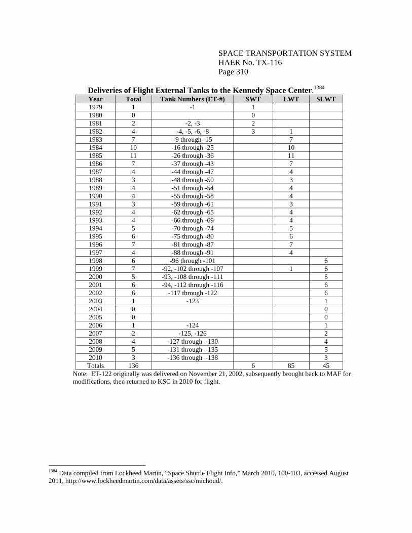
SPACE TRANSPORTATION SYSTEM HAER No. TX-116 Page 310
Deliveries of Flight External Tanks to the Kennedy Space Center.1384 Year Total Tank Numbers (ET-#) SWT LWT SLWT 1979 1 -1 1 1980 0 0 1981 2 -2, -3 2 1982 4 -4, -5, -6, -8 3 1 1983 7 -9 through -15 7 1984 10 -16 through -25 10 1985 11 -26 through -36 11 1986 7 -37 through -43 7 1987 4 -44 through -47 4 1988 3 -48 through -50 3 1989 4 -51 through -54 4 1990 4 -55 through -58 4 1991 3 -59 through -61 3 1992 4 -62 through -65 4 1993 4 -66 through -69 4 1994 5 -70 through -74 5 1995 6 -75 through -80 6 1996 7 -81 through -87 7 1997 4 -88 through -91 4 1998 6 -96 through -101 6 1999 7 -92, -102 through -107 1 6 2000 5 -93, -108 through -111 5 2001 6 -94, -112 through -116 6 2002 6 -117 through -122 6 2003 1 -123 1 2004 0 0 2005 0 0 2006 1 -124 1 2007 2 -125, -126 2 2008 4 -127 through -130 4 2009 5 -131 through -135 5 2010 3 -136 through -138 3
Totals 136 6 85 45 Note: ET-122 originally was delivered on November 21, 2002, subsequently brought back to MAF for modifications, then returned to KSC in 2010 for flight.
1384 Data compiled from Lockheed Martin, “Space Shuttle Flight Info,” March 2010, 100-103, accessed August 2011, http://www.lockheedmartin.com/data/assets/ssc/michoud/.
SPACE TRANSPORTATION SYSTEM HAER No. TX-116 Page 311
General Description and Coordinate System1385
The ET (Figure No. D-17) measured 153.8’ in length, 27.6’ in diameter, and had a propellant capacity of approximately 1.6 million pounds (535,000 gallons). The inert weight of the SLWT was roughly 58,500 pounds. The ET was comprised of three primary structures: two separate propellant tanks and an intertank section located between them (Figure Nos. D-18, D-19). The upper tank held LO2 at minus 297 degrees F. The lower tank contained LH2 at minus 423 degrees F. Flanges at the top and bottom of the ribbed intertank connected the three elements. All power, pressure, and purges were received from either the orbiter or ground facility. The only active components on the ET were the vent/relief valves.1386 The SLWT was made of aluminum-lithium and steel alloys and titanium. A SOFI material approximately one inch thick was applied to the exterior of the entire tank, with 282 square feet of underlying ablators to prevent ice build-up and to protect the tank from engine and aerodynamic heating.1387 Overall, the ET contained 481,450 parts, 38 miles of electrical wiring, 1,000 feet of insulated sleeving, 50 feet of coaxial cable, 4.7 miles of tape, 7,000 feet of safety wire, and 4,000 pounds of thermal protection materials. It required more than one-half mile of welding to join together the aluminum panels that formed the tank.1388 The baseline description of the SLWT contained in the following sections is from Lockheed Martin’s Space Shuttle External Tank System Definition Handbook SLWT, dated December 1997. Upgrades and improvements which post-date 1997 have been incorporated, to the extent possible. The physical and functional descriptions are organized by major ET system. Included are descriptions of the structures system, propulsion system, electrical system, and TPS, as well as interface hardware. For the purposes of clarity and consistency, references to stations within the ET coordinate system have been minimized. The ET coordinate system used three reference planes. The “Y” reference plane intersected the ET (and attached orbiter) longitudinal centerline. The “Z” reference plane was parallel to the longitudinal centerline of the ET and the attached SRBs, and was arbitrarily located 400” from the ET longitudinal centerline in a direction opposite the attached orbiter. The “X” reference plane was nominal to the Y and Z planes, and was arbitrarily located 2,058” forward of the center of the two aft ET-to-orbiter structural attach points. Fore and aft distances along the longitudinal ET axis were designated ET “Stations,” and were measured as positive (+) distances from the X reference plane. Right and left designations are in the +Y and –Y directions, respectively, coinciding with the orbiter pilot’s right and left 1385 This description focuses on the SLWT because it was the end state ET for the SSP. 1386 Lockheed Martin, Space Shuttle External Tank, System Definition Handbook SLWT, Layout Drawings Volume II (New Orleans, LA: Lockheed Martin, December 1997), 4-2. 1387 Lockheed Martin, “Fact Sheet Space Shuttle External Tank,” July 2011, accessed August 2011, http://www.lockheedmartin.com/data/assets/ssc/michoud/FactSheets/ETFact Sheet.pdf. 1388 Lockheed Martin, “Space Shuttle External Tank Statistics and Comparisons,” June 2011, accessed August 2011, http://www.lockheedmartin.com/data/assets/ssc/michoud/FactSheets/ETStatistics.pdf.
SPACE TRANSPORTATION SYSTEM HAER No. TX-116 Page 312
perspective, when the orbiter was attached to the ET. Angular measurements around the circumference of the ET (within an X plane) were referenced to 0 degrees in the +Z direction (toward the orbiter); positive angles were clockwise looking forward.1389 Structures System Three primary elements comprised the ET structures system: the LO2 tank, located in the forward position; the aft-positioned LH2 tank; and the unpressurized intertank, which connected the two propellant tanks. The intertank housed instrumentation and processing equipment, and provided one of the attachment structures for the SRBs. The LH2 tank was approximately twice as large as the LO2 tank. The basic structure was made of aluminum alloys 2024, 2195, 2219, and 7075. Liquid Oxygen Tank The LO2 tank was an ogive-shaped aluminum monocoque1390 structure, which was designed to reduce aerodynamic drag and aerothermodynamic heating (Figure Nos. D-20, D-21). It was composed of a fusion-welded assembly of preformed chemically-milled gores and panels, and machined fittings and ring chords. The LO2 tank had a volume of approximately 19,463 cubic feet designed to contain approximately 1.38 million pounds (145,000 gallons) of oxidizer. The empty weight was approximately 12,000 pounds. The LO2 tank measured 27.6’ in outside diameter and 54.6’ long, and operated in a pressure range of 20 to 22 pounds per square inch, gauge (psig). Vortex and slosh baffles were mounted in the LO2 tank to minimize liquid residuals and damp fluid motion. A 17”-diameter feedline conveyed the LO2 from the LO2 tank through the intertank, then outside the ET to the aft right-hand ET/orbiter disconnect umbilical. The LO2 flowed through the feedline at approximately 2,787 pounds per second, with the SSMEs operating at 104 percent, or a maximum flow of 17,592 gallons per minute. The LO2 tank’s nose cone, which contained electrical system components, functioned to reduce drag and heating, and also acted as a lightning rod.1391 Aluminum alloys (2024, 2195, and 2219) were used exclusively in the fabrication and assembly of the LO2 tank structure. Compared with the LWT design, the weld lands in the SLWT were increased by up to 0.25” in thickness.1392 The “robust weld lands” connected the ogive to ogive, barrel panel to barrel panel, dome gore to dome gore, and dome cap to dome body.
1389 Martin Marietta, Handbook, Configuration & Operation, III-5. 1390 Monocoque is a type of construction in which the outer skin carries all or a major part of the stresses, as distinguished by an internal frame or truss system. 1391 USA, Crew Operations, 1.3-2; Lockheed Martin Corporation, “External Tank,” 2010, accessed August 2010, http://www.lockheedmartin.com/ssc/michoud/ExternalTank/index.html. 1392 Lockheed Martin, Handbook (SLWT), 6-3.
SPACE TRANSPORTATION SYSTEM HAER No. TX-116 Page 313
The major assemblies which comprised the LO2 tank were the nose cone and cover plate, the forward and aft ogive sections, the cylindrical barrel section, the slosh baffle, and the LO2 aft dome (Figure No. D-22). A description of each follows. A nose cone and a flat removable cover plate topped the ogive nose section. The conical-shaped nose cone, mounted on the ogive, was 2.54’ long and was constructed of 0.252”- to 0.336”-thick epoxy graphite composite. The design for the original SWT nose cone used over 1,000 fasteners to assemble multiple sheet metal pieces. It was covered with TPS materials. In June 1989, MSFC and Martin Marietta began developing a new advanced nose cone constructed from a high-temperature resistant composite. The new composite nose cone was manufactured by the MSFC Productivity Enhancement Center from eighteen to twenty-one sheets of graphite phenolic cloth inside a graphite mold. The new design could withstand temperatures in excess of 900 degrees F, thus eliminating the need for the TPS. The composite nose cone resulted in a weight savings of 21 pounds.1393 The forward end of the nose cone featured a cast aluminum lightning rod, which protected the entire Space Shuttle vehicle at the pad. The lightning rod, which measured 13.34” long, was attached to the nose cone by six 0.25”-diameter bolts. The nose cone featured provisions for two stainless steel louvers that were part of the oxidizer vent system. It also had a penetration for the electrical cable tray and the LO2 pressurization line. The nose cone was attached to the nose cone brackets by twenty-nine 3/8”-diameter bolts.1394 The removable cover plate provided a location for mounting propulsion system components. Machined from 2219 aluminum plate, it measured 39” in diameter, 0.35” thick, and weighed 79 pounds. The cover plate incorporated machined stiffeners, and was joined to the ogive forward ring by ninety-two 5/16”-diameter bolts. A pressure seal of Naflex provided a gastight joint. Removal of the plate provided a 36”-diameter access opening to the LO2 tank.1395 The 612”-radius ogive section was formed by welding a forward fitting, eight forward gores, and twelve aft gores. The forward fitting was a one-piece, machined forging that included the cover plate mating-and-sealing surface. It was butt welded to the forward ogive gore assembly. The forward ring contained a 1.4” penetration for the electrical feed-through connector.1396 One forward and one aft gore section had locally thickened skin pads and weld tabs for the attachment of support brackets for the LO2 pressurization line and electrical cable tray. The skin pads and weld tabs continued over the adjoining barrel section.1397 All ogive gore panels were 1393 Jenkins, Space Shuttle, 423. Two non-production units were tested in January 1994, and the first production unit was used on ET-81. 1394 Lockheed Martin, Handbook (SLWT), 6-6. 1395 A Naflex seal is a metallic seal with a redundant sealing feature; it was created by North American Aviation, Inc. Lockheed Martin, Handbook (SLWT), 6-7, 6-16. 1396 Lockheed Martin, Handbook (SLWT), 6-7. 1397 Lockheed Martin, Handbook (SLWT), 6-8.
SPACE TRANSPORTATION SYSTEM HAER No. TX-116 Page 314
chemically-milled on both sides, and edge trimmed and butt welded during assembly to form the ogive section. An extruded “T” ring frame was butt welded to the aft edge of the ogive section and to the forward edge of the barrel section of the LO2 tank. This frame provided for the forward attachment of the slosh baffle and contributed to the tank’s stability. The frame was pre-formed to a circular shape in four, ninety degree segments. The four segments were butt welded together to complete the frame.1398 Mounted to the forward ogive gore panel was the mast for the LO2 level and temperature sensors. The mast measured approximately 82.8” long, with a 3.1” outside diameter and a wall thickness of 0.083”.1399 Also attached to the forward ogive gore, by means of butt welding, was a fitting made from a single piece of machined 2219 aluminum. This fitting provided attachment and sealing features for the nose cone and the cover plate.1400 The cylindrical barrel section, which measured approximately 98.2” in length, was fabricated from four chemically-milled and formed panels of 2219 aluminum plate welded together. Skin thicknesses on the two side panels were tailored in grid fashion to accommodate SRB thrust loads. The other two panels were identical except for three thickened skin pads and weld tabs on one panel. These tabs supported the cable tray and GO2 pressure line extending over the barrel.1401 The LO2 slosh baffle assembly, fabricated in two sections, consisted of aluminum rings tied together with longitudinal stringers and tension straps. The main stabilizing ring frame served as the aft baffle support ring at the juncture of the barrel section and the LO2 tank dome. This ring was comprised of thirty-two machined forgings alternating with thirty-two stiffened webs, plus aluminum chord. The webs of the frames, web stiffeners, and stringers were riveted, while the tension straps were pin joined.1402 The baffle assembly, primarily made of 2024 aluminum sheet, was designed to prevent fluid slosh. The LO2 aft dome section was comprised of the aft (dome-to-barrel) ring frame, twelve identical gore segments, and a 140”-diameter dome end-cap. The end-cap included the LO2 contoured feed outlet, a 36”-diameter manhole access, and a 1.28”-diameter penetration for the aft LO2 low-level sensor electrical feed-through connector. The dome was assembled by welding together three pre-formed and chemically-milled gore skins and a quarter section of the extruded ring frame to form a dome quarter panel. The quarter panels were welded together, after which the dome end-cap was welded onto the assembly. The aft ring frame served as the weld juncture
1398 Lockheed Martin, Handbook (SLWT), 6-9. 1399 Lockheed Martin, Handbook (SLWT), 6-15. 1400 Lockheed Martin, Handbook (SLWT), 6-16. 1401 Lockheed Martin, Handbook (SLWT), 6-10. 1402 Lockheed Martin, Handbook (SLWT), 6-10, 6-17.
SPACE TRANSPORTATION SYSTEM HAER No. TX-116 Page 315
between the barrel section and the dome. The outer flange was mated to the intertank with 194 bolts of 9/16”-diameter.1403 The variable skin thickness of the dome gore panels was accomplished by chemical milling. Panel members were reinforced by a series of circumferential bands. The spherical dome cap was spun formed and then chemically milled on both sides. The cap featured cutouts for the contoured LO2 outlet/inlet fitting and the manhole fitting, and for an electrical feed-through connector. The outlet/inlet fitting was welded to the dome cap.1404 A vortex baffle was installed to the end-cap, internal to the tank. The baffle served to reduce fluid swirl resulting from the Coriolis effect, and prevented entrapment of gasses in the delivered LO2. The 160”-diameter vortex baffle was attached to the dome cap at four locations, with two fasteners at each location. The assembly included four webs with upper and lower caps, and vertical stiffeners stabilized with diagonal straps. The webs and caps were joined at the center with a splice plate at the bottom and a splash plate on top. The 0.02”-thick webs contained a total of 124 holes which served to both lighten the structure and reduce the slosh locally. A four-segment, 800-micron filter screen, which helped to anchor the baffle assembly, was mounted to the lower caps of the vortex baffle.1405 A 45”-diameter manhole fitting, welded to the dome cap, provided a 36”-diameter clear access to the tank interior. The fitting featured ninety-two attachment points for mating to the machined aluminum manhole cover. The fifty-seven pound manhole cover measured 40.32” in overall diameter and 0.185” thick at the center. It provided an interfacing sealing surface with the manhole fitting, as well as a means for making a leak check of the primary seal.1406 Intertank The intertank was a semi-monocoque, cylinder-shaped structure comprised of external stringers and internal frames (Figure No. D-23). It connected the two propellant tanks, housed instrumentation and processing equipment, and provided the attachment structure for the forward end of the SRBs. Flanges on the bottom and top ends of the intertank attached with the LO2 and LH2 tank assemblies. The intertank measured 270” (22.5’) long, 331” (27.6’) in diameter, and weighed approximately 12,100 pounds. Aluminum alloys were used exclusively in the intertank structure, with the exception of fasteners and the SRB fitting socket inserts, which were steel.1407 The primary functions of the intertank were to receive and distribute all thrust loads from the SRBs, and to provide structural continuity. The intertank also provided a carrier plate assembly
1403 Lockheed Martin, Handbook (SLWT), 6-11. 1404 Lockheed Martin, Handbook (SLWT), 6-12. 1405 Lockheed Martin, Handbook (SLWT), 6-13. 1406 Lockheed Martin, Handbook (SLWT), 6-14. 1407 Lockheed Martin, Handbook (SLWT), 7-3.
SPACE TRANSPORTATION SYSTEM HAER No. TX-116 Page 316
that interfaced with the fluid, electrical, and pneumatic systems ground facilities.1408 The major structural elements of the intertank included two thrust panels, six stringer-stiffened panels, ring frames, and the SRB beam (intertank crossbeam) (Figure No. D-24). The two thrust panels were rough machined from 2219 aluminum plate, and formed to cylindrical segments with a radius of approximately 165”. They were final machined to a finished size of 2.06” by 130” by 270.35”. Skin thickness was variable, depending on the location. Each panel was comprised of twenty-six external parallel ribs. These, in addition to seven circumferential ribs, were designed to prevent buckling of the intertank. Rib thickness ranged between a minimum of 0.17” to 1.05” near the SRB fittings; circumferential rib thickness varied from 0.5” at the center of the panel to 0.18” at the outer edge.1409 Two longerons of extruded aluminum were mechanically fastened to each thrust panel, one on each side of the SRB fitting, to provide added stability. The longerons measured 114” long, 3” wide, and 5” high, with a maximum thickness of 0.22”. They extended through the two smaller ring frames, and ended near the LO2 tank attachment flange ring.1410 Each of the six skin/stringer panels was made of two 2090 aluminum sheet skins mechanically spliced using longitudinal butt straps. Skin doublers, also of 2090 aluminum sheet, provided reinforcement for areas where the skin was penetrated for the ET intertank carrier plate assembly, the access door opening, venting, and the entry of cables and lines. Additional skin reinforcing doublers were located adjacent to the thrust panels and the LO2 tank attachment flange ring. The skin doublers were located both internally and externally. Eighteen external stringers were equally spaced around each panel to provide buckling and flutter resistance, to distribute loads to the attachment flanges, and to provide for the attachment of mounting brackets for propulsion and electrical subsystem lines and cable trays. The aluminum stringers were mechanically fastened to the skin panels and flanges. The intertank featured one main ring frame, which distributed SRB loads to the intertank skin, and four intermediate ring frames, which provided intertank skin panel stability. The main ring frame adjoined the SRB thrust fitting. It was constructed of four quadrant subassemblies, each built of outer and inner tee chords machined from 7075-T73511 aluminum extrusions and joined to webs to form an I-beam measuring 20” deep. The outer chords were fastened to the cylindrical skin panels. The width of each outer chord was 6” for a length of 53” at the end which fastened to the SRB fitting, 6” for a length of 54” adjacent to the access door in one quadrant, 3.8” at the end spliced to the adjacent chord, and 3.2” wide for the remainder of its length. The inner chord was a uniform 3.86” wide. The web thickness varied from 0.180” to 0.05” with increasing distance from the SRB fitting.1411
1408 Lockheed Martin, Handbook (SLWT), 7-2. 1409 Lockheed Martin, Handbook (SLWT), 7-4, 7-5. 1410 Lockheed Martin, Handbook (SLWT), 7-6. 1411 Lockheed Martin, Handbook (SLWT), 7-7.
SPACE TRANSPORTATION SYSTEM HAER No. TX-116 Page 317
The four intermediate ring frames were of similar construction, forming an I-beam measuring 12” deep. However, there were two significant differences among the four intermediate ring frames. The ring frame adjacent to the access door had a locally wider outer chord section. Secondly, the two ring frames located in the forward half of the intertank had the outer chords cut and portions of the webs notched to straddle the two longerons.1412 The SRB beam assembly was a rectangular box beam consisting of top and bottom chords, stiffened webs, stability bulkheads, and SRB thrust fittings, all mechanically joined. It measured 42.95” deep at the center and tapered to 26” (at the ends) by 15” wide. The SRB beam spanned 345” between the centerlines of the two SRB thrust fittings which formed the ends of the assembly. The top (forward) chord was an extruded and machined 7075-T86 aluminum channel with extensions for attaching web members. The bottom chord was similar to the top, and both were fastened to the SRB fitting. Side webs of 7075-T6 aluminum sheet were joined to the top and bottom beam chords. The webs located in the area of the ring frame junction with the SRB fitting were reinforced with tee and angle stiffeners. Two skin doublers provided further structural strength at this location. The two intertank SRB thrust fittings, of machined aluminum (7050-T73) forgings, were mechanically fastened to the chord ends of the SRB beam, the machined gusset fittings, the main frame outer chord, and the thrust panel.1413 Two vent openings, each with an area of 6 square inches, were provided at the forward end of the intertank. They were for venting during preflight environmental conditioning and for equalization of internal/external pressures in flight. Each pressure vent consisted of an elliptical-shaped tube which was installed on the intertank skin.1414 The intertank featured an access door made of composite graphite polyimide material, with sixteen plies on the skin and eight plies on the stringers. The door, recessed from the intertank stringer tops, was attached to the intertank with forty-four bolts.1415 Four aerodynamic fairings enclosed the penetrations for the LO2 feedline, the gaseous hydrogen pressure line, and at the two electrical cable tray locations. The fairings were fastened to the tops of the stringers immediately fore and aft of the penetration openings. In addition, supports for the cable trays and propulsion lines were fastened to the stringers by formed-sheet and machined brackets that bridged the stringer gaps.1416
1412 Lockheed Martin, Handbook (SLWT), 7-8. 1413 Lockheed Martin, Handbook (SLWT), 7-9, 7-10. 1414 Lockheed Martin, Handbook (SLWT), 7-10. 1415 Lockheed Martin, Handbook (SLWT), 7-11. 1416 Lockheed Martin, Handbook (SLWT), 7-12.
SPACE TRANSPORTATION SYSTEM HAER No. TX-116 Page 318
Liquid Hydrogen Tank The cylindrical-shaped LH2 tank was a semimonocoque structure fabricated exclusively of aluminum alloys (Figures No. D-20, D-25, D-26). It was comprised of welded barrel sections and ring frames, and was capped on both ends by modified ellipsoidal domes. The LH2 tank measured 331” (27.6’) in outside skin diameter and 1,160” (96.7’) long. It had a volume of 52,371 cubic feet, and held approximately 231,000 pounds (390,000 gallons) of propellant fuel, which included a 3 percent ullage.1417 The empty weight was approximately 29,000 pounds.1418 The LH2 tank was roughly two-and-one-half times larger than the LO2 tank, but weighed only one-third as much when filled. This was because LO2 is sixteen times heavier than LH2. The LH2 tank contained an anti-vortex baffle and siphon outlet to transmit the LH2 from the tank through a 17” line to the left aft umbilical. The LH2 feedline flow rate was 465 pounds per second with the SSMEs at 104 percent, or a maximum flow of 47,365 gallons per minute. The operating pressure range was 32 to 34 psia. A frame located at the juncture of the forward dome and the forward barrel contained a flange for joining the LH2 tank to the intertank. This frame also provided the structure for the ET/orbiter forward attach point. A frame at the juncture of the aft dome and aft barrel contained the structure for the ET/SRB aft attachment, as well as for the aft ET/orbiter attachment.1419 The major assemblies which comprised the LH2 tank were the forward and aft domes, the cylindrical barrel sections, and the major ring frames (Figure No. D-27). A description of each follows. The LH2 forward dome was a welded assembly of twelve gore segments and a dome cap, all fabricated from 2195-T8A4 and 2219-T87 aluminum plate. The dome shape and manufacturing techniques were the same as for those used for the LO2 tank. Gore skin thickness was tapered to maintain stress uniformity and each gore was chemically milled on both sides to equalize skin stresses. Thickness varied from a minimum of 0.066” near the aft edge of the gore to 0.084” near the dome cap. The membranes were reinforced by a series of circumferential chemically milled bands. The dome cap measured 140” in diameter and was 0.092” thick, with the exception of the weld lands. It was machined to accommodate installation of the LH2 vent valve, the LH2 pressure line fitting, the electrical feed-through fitting, the forward manhole fitting, and the LH2 tank manhole covers.1420
1417 Ullage is defined as: 1. the amount of liquid within a container that is lost, as by leakage or evaporation; 2. The amount by which a container falls short of being full; and 3. The free space above the liquid contained in a barrel, drum, or tank, provided to accommodate the expansion of the liquid. http://www.the freedictionary.com/ullage; www.businessdictionary.com/definition/ullage.html. 1418 USA, Crew Operations, 1.3-3; Lockheed Martin Corporation, “External Tank.” 1419 Lockheed Martin, Handbook (SLWT), 5-2. 1420 Lockheed Martin, Handbook (SLWT), 8-5.
SPACE TRANSPORTATION SYSTEM HAER No. TX-116 Page 319
The LH2 tank aft dome was similar in shape and construction to the LH2 tank forward dome and the LO2 tank domes. The major difference between it and the LH2 tank forward dome was the provision for the mounting of fittings. Provisions for tank access were incorporated in the aft dome cap, and the manhole fitting was similar to those on both the LO2 tank domes and the LH2 tank forward dome. Unlike the LWT design, the SLWT did not have a second manhole cover.1421 The fitting for the LH2 feedline was unique because of the angle at which it penetrated the dome, and because of the compound curve of its flange. A vortex baffle assembly was located at the LH2 feedline siphon outlet just above the aft dome. This assembly was comprised of four identical baffle webs formed of 2024 aluminum. Outer frame chords of extruded tee-shaped aluminum were riveted to each web. The webs contained fluid damping holes and stiffeners.1422 The four cylindrical barrel sections were fabricated of 2195-T8M4 aluminum plate. Each section was a welded assembly made from eight orthogrid stiffened skin panels. Two basic orthogrid pocket configurations were used throughout the skin panels. The skin membrane thickness varied from panel to panel, from a minimum of 0.084” to a maximum of 0.555”. The thickness of the weld lands at the edges of each panel was generally 0.325”. The skin panels included provisions for mounting support fittings for propulsion system lines and electrical cable trays. Two longerons, made from 2219-T6 aluminum forgings, were butt welded into the skin panels of the aft barrel section. The longerons measured approximately 181.75’ long by 32.496” wide.1423 Five major ring frames joined the dome and barrel sections together. These frames were I-Beam-shaped with varying depths and chord configurations. With one exception, the frames were fabricated in 90-degree segments at the subassembly level. They were then spliced by circumferential weldments along the outer chord, and by mechanically attached splice plates and angles at the web and inner chord. The outer chord was made from extruded 2195-T8A3 and 2219-T8511 aluminum; the inner chord was fabricated of extruded 2024-T8511 aluminum. The webs were made of 2024-T81 sheet and plate aluminum.1424 The forward and two aft major ring frames were stiffened by radially-oriented web stiffeners. The other two frames required no web stiffening. Each major ring frame was stabilized by struts which tied the frame inner chord to the barrel orthogrid at circumferential locations.1425 Propulsion System The ET contained all the fuel and oxidizer to feed the orbiter’s three main engines (Figure No. D-28). These propellants were delivered between the tanks and orbiter interface through 17”-diameter feedline disconnects. The complete ET propulsion system was comprised of the LO2
1421 This feature was eliminated on the aft dome as a weight saving measure. 1422 Lockheed Martin, Handbook (SLWT), 8-14, 8-15. 1423 Lockheed Martin, Handbook (SLWT), 8-6, 8-7, 8-19. 1424 Lockheed Martin, Handbook (SLWT), 8-4, 8-9. 1425 Lockheed Martin, Handbook (SLWT), 8-9 through 8-13.
SPACE TRANSPORTATION SYSTEM HAER No. TX-116 Page 320
and LH2 feed systems; the LO2 and LH2 tank pressurization and vent/relief systems; the intertank and tank environmental control systems; and the ET intertank carrier plate assembly. Feed Systems
Each ET contained five propellant umbilicals which fueled the main engines. Two umbilicals were for the LO2 tank (one for LO2 and one for GO2) and three were for the LH2 tank (two for LH2 and one for GH2). These lines carried the fuel, oxidizer, gases, electrical signals, and power between the tank and the orbiter. Eight propellant depletion sensors, designed for propellant loading control, were located inside the ET, four each for the fuel and the oxidizer. The LO2 oxidizer sensors were initially mounted on the LO2 feedline manifold (later relocated to the oribiter side of the feedline), and the LH2 fuel sensors were mounted on the bottom of the LH2 tank. The orbiter’s onboard computers monitored the mass of the Shuttle vehicle, which lessened as the fuel was depleted. If any two of the fuel or oxygen sensors read a dry condition, the engines would be shut down and the ET jettisoned. The location of the sensors allowed the maximum amount of oxidizer to be consumed, while allowing sufficient time to shut down the engines before the oxygen pumps ran dry (known as “cavitation”). In addition, 1,100 pounds of LH2 were loaded over and above that required by the 6:1 oxidizer/fuel engine mixture ratio to assure that when the main engine cutoff occurred, the propellant mixture was fuel rich. Otherwise, oxidizer-rich engine shutdowns could cause burning and severe erosion of the engine components.1426 The LO2 feed system consisted of the LO2 feedline and the helium inject line. The LO2 feedline was a 17”-inner diameter insulated pipe made of aluminum and corrosion-resistant steel. It ran up the side of the LH2 tank through a slotted port in the intertank skin to a joint on the outlet of the LO2 tank.1427 The LO2 feedline assembly consisted of nine sections, including the forward flexible assembly, the flexible elbow, four straight sections, an aft flexible assembly, an aft elbow, and the ET/orbiter disconnect assembly. These sections were joined with bolted flanges which contained seals to control leakage. The forward flexible assembly was located entirely within the intertank. The elbow assembly penetrated the intertank skin and ran down the side of the ET a distance of approximately 108”. The four straight sections ran down the side of the LH2 tank from the flexible elbow to the aft flexible assembly, a distance of approximately 840”. The upper section was 247.7” long, the middle two sections were 246.7” long, and the lower section was 102.5” long. The aft elbow joined the 76.6”-long aft flexible assembly to the ET half of the LO2 disconnect at the right ET/orbiter umbilical disconnect plate. The straight sections were made of
1426 NASA KSC, “The Lightweight Space Shuttle External Tank,” NASA Fact Sheet (Florida: Kennedy Space Center, February 1983), Sweetsir Collection, Box 50E.3, Folder 125, Kennedy Space Center Archives, Florida; USA, Crew Operations, 1.3-3, 1.3-4. 1427 Lockheed Martin, Handbook (SLWT), 9-9.
SPACE TRANSPORTATION SYSTEM HAER No. TX-116 Page 321
2219 aluminum and the aft elbow was a casting of A357T6 aluminum. The flexible sections were fabricated of 347 stainless steel, 21-6-9 stainless steel and Inconel 718. The feedline had flexible joints in five places which allowed for fabrication and installation tolerances, thermal expansion, and relative motion during liftoff and flight. Seven supports secured the LO2 feedline to the tank structure, including five pivoting supports located along the length of the LH2 tank.1428 The helium inject line, made of 3/8” outer diameter stainless steel tubing ran through the intertank, down the LH2 tank, inside the cable tray, and into the LO2 aft elbow. This line introduced a controlled flow of helium into the aft end of the LO2 feedline to prevent geysers during propellant loading and hold before launch. It was not operational during flight.1429 The LH2 feed system consisted of the LH2 feedline and the LH2 recirculation line. The LH2 feedline was a 17”-inner diameter pipe made of aluminum and corrosion-resistant steel. The internal/external configuration ran from the ET half of the LH2 disconnect through a flanged port on the upper LH2 tank aft dome, to near the bottom of the dome. The uninsulated internal feedline section consisted of a 35”-long articulated bellows segment and a bell-mouth siphon segment. The LH2 internal feedline assembly was fabricated from 304L and 321 stainless steel. The 42”-long external feedline section, fabricated of 321 and 347 stainless steel, 21-6-9 stainless steel, and Inconel 718, contained an articulated bellows assembly with an insulation jacket to prevent the formation of liquid air during countdown and launch operations.1430 The LH2 recirculation line measured 4” in diameter by approximately 60” long. It was constructed of 21-6-9 stainless steel and insulated with SS-1171 and SLA-561. The line connected the 4” disconnect valve in the ET/orbiter umbilical assembly with the LH2 tank. It carried warm LH2 from the engine back to the ET during propellant loading and hold. The recirculation line incorporated two free bellows assemblies with argon gas-filled jackets, similar to the LH2 feedline.1431 Tank Pressurization and Vent/Relief System The pressurization and vent relief system, which regulated the tank pressure, incorporated the LO2 and LH2 tank pressurization subsystems and the LO2 and LH2 tank vent/relief subsystems. The LO2 Tank Pressurization Subsystem consisted of a GO2 pressurization line fabricated of Inconel 718 corrosion-resistant steel tubing. The 2”-outer diameter line extended from the GO2 pressurization disconnect on the aft right ET/orbiter umbilical, up the exterior of the LH2 tank, intertank, and LO2 tank, and terminated at the LO2 tank forward cover plate. The pressurization
1428 Lockheed Martin, Handbook (SLWT), 9-10 through 9-12. 1429 Lockheed Martin, Handbook (SLWT), 9-14. 1430 Lockheed Martin, Handbook (SLWT), 9-15 through 9-17. 1431 Lockheed Martin, Handbook (SLWT), 9-18.
SPACE TRANSPORTATION SYSTEM HAER No. TX-116 Page 322
line was comprised of nine separate line assemblies: the upper flex line assembly, the upper curved line assembly, the upper transition line assembly, the mid flex line assembly, four straight assemblies, and the lower flex line assembly.1432 All line sections were mated to each other and to their interfaces with flanged joints. Naflex Inconel 718 seals were used at each mechanical joint. A leak-test port was located at each joint to provide access between the primary and secondary sealing surfaces. The pressurization line was supported by thirty-three sliding supports and two fixed supports. The latter were located at the aft end of the intertank and at the forward end of the LO2 tank.1433 A cylinder-shaped diffuser, located at the GO2 pressurization line outlet, was secured internally to the LO2 tank. The LH2 Tank Pressurization Subsystem consisted of a 2”-outer diameter tube made of corrosion-resistant steel. The line extended from the GH2 pressurization disconnect on the aft left umbilical, to the LH2 tank, up into the intertank, and terminated at the cover plate mounted to the LH2 tank forward dome cap. A cylindrical-shaped GH2 diffuser was mounted to the cover plate inside the LH2 tank. The GH2 pressurization line consisted of an upper flex assembly, a straight line assembly, a lower flex assembly, a straight line section, and an aft flex assembly. The subsystem also included eleven flexible joints, two supports for the line upper assembly located within the intertank along the LH2 tank dome, and other sliding and fixed supports.1434 The LO2 Tank Vent/Relief Subsystem consisted of a two-stage GO2 vent/relief valve, a vent manifold, and two louver assemblies. This dual-function valve could be opened by ground support equipment for the vent function during prelaunch, and during flight when the ullage pressure of the LH2 tank reached 36 psig, or the ullage pressure of the LO2 tank reached 31 psig.1435 The valve inlet was bolted to a port on the LO2 tank forward bulkhead cover plate. The outlet connected to the vent manifold. The inner manifold contained a bellows assembly. GO2 was discharged on opposite sides of the nose cap through the louvers.1436 The LH2 Tank Vent/Relief Subsystem included a single vent/relief valve inlet bolted to a fitting welded into the LH2 tank forward dome. The outlet was bolted to a vent duct, which in turn bolted to the vent disconnect on the intertank umbilical disconnect plate. The vent duct was bolted to the vent valve. A steel vent valve actuation line led from a 3/8”-diameter disconnect at the intertank umbilical carrier plate to an actuation port on the valve. The line followed and was attached to the side of the vent duct.1437
1432 Lockheed Martin, Handbook (SLWT), 9-19, 9-20. 1433 Lockheed Martin, Handbook (SLWT), 9-21. 1434 Lockheed Martin, Handbook (SLWT), 9-23, 9-24. 1435 USA, Crew Operations, 1.3-3. 1436 Lockheed Martin, Handbook (SLWT), 9-26, 9-27. 1437 Lockheed Martin, Handbook (SLWT), 9-30.
SPACE TRANSPORTATION SYSTEM HAER No. TX-116 Page 323
Environmental Conditioning System The ET environmental conditioning system consisted of an intertank purge and a hazardous gas detection system. These served to purge the intertank, the nose cap, and propellant tanks, as well as to sample the intertank environment for gas composition during propellant loading operations. The intertank was purged with dry, heated GN2 during propellant loading to prevent condensation of moisture, to preclude air ingestion through the intertank vents, and to avert a buildup of hazardous gases.1438 Similarly, heated GN2 purged the ET nose cone cavity to provide an inert atmosphere and to minimize the ice/frost formation that would be caused by cold vent gas. The gas flow rate was approximately 13.5 pounds per minute.1439 ET Intertank Carrier Plate Assembly The ET intertank carrier plate assembly was where the ground umbilical carrier assembly (GUCA) and the facility lines mated. The flight half of the ET/ground umbilical interface provided for the servicing of the pressurization and vent system, hazardous gas detection system, operational instrumentation system, and electrical power.1440 The plate assembly was machined from aluminum alloy 2219 plate, and mechanically fastened to the skin panel by four flanges.1441 Electrical System The ET’s electrical system provided operational instrumentation, cabling, electromagnetic compatibility, and lightning protection. All electrical power was supplied by the orbiter, except for heater power which was provided by the ground facilities. Operational Instrumentation The operational instrumentation for the ET electrical system included thirty-five flight systems and ground systems sensors, as well as switches and the ice/frost heating subsystem. Of the sensors, four gas temperature sensors and two LO2 ullage pressure sensors were ground measurements; the others were flight measurements. The instrumentation provided status data to the orbiter, or to the launch facility, regarding temperature, pressure, and liquid levels prior to launch. After the Columbia accident, ground temperature measurements were added to control the bipod heaters. The thirty-five sensors included the following:
• Two resistant-type transducer ullage temperature sensors, one for LO2 and the other for LH2;
1438 Lockheed Martin, Handbook (SLWT), 9-31. 1439 Lockheed Martin, Handbook (SLWT), 9-34. 1440 Lockheed Martin, Handbook (SLWT), 9-34. 1441 Lockheed Martin, Handbook (SLWT), 7-12.
SPACE TRANSPORTATION SYSTEM HAER No. TX-116 Page 324
• Four resistant-type transducer gas temperature sensors, including two in the intertank and
two mounted on the nose cone plate; • Four potentiometer-type, absolute-pressure transducer LH2 pressure sensors, of which
one was for backup purposes only; • Three variable reluctance-type, differential pressure transducer LO2 ullage pressure
sensors; • Two variable reluctance-type, pressure transducer LO2 ullage loading pressure sensors; • Twenty liquid level and depletion sensors which indicated the presence or absence of
LO2 or LH2.1442 The LO2 depletion sensors were located in the orbiter while the LH2 depletion sensors were located in the ET.
The LH2 tank incorporated two vent valve position indicator switches to denote OPEN or CLOSED positions prior to launch; the LO2 tank had a CLOSED position only. These three vent valve switches were integral parts of the valve assemblies.1443 The ice/frost heating subsystem consisted of two calrod heaters mounted on each of the forward bipod spindle assemblies. These functioned to minimize ice accumulation on the bipod fitting. The heaters were powered and regulated by the launch facility.1444 Cabling Both ET and Orbiter/SRB interface cabling were components of the electrical system. The ET cabling system provided hardware connections between the ET electrical components and orbiter interfaces. The system consisted of wiring, connectors, protected wire splices used in areas where connectors were not required, cabling, and disconnect panels located in the intertank that held bulkhead connectors. External cabling on the ET was routed through protective aluminum cable trays. The cable trays had removable covers and were protected by TPS on the external surfaces. The primary tray ran along the right shoulder of the ET. Twelve orbiter/SRB interface cables were located on the ET. The cables, which did not connect into the ET electrical system, ran through protective cable trays.1445 Lightning Protection The primary lightning protection feature for flight was the nose spike located on the nose cone, described previously.
1442 Lockheed Martin, Handbook (SLWT), 10-2 through 10-6. 1443 Lockheed Martin, Handbook (SLWT), 10-7. 1444 Lockheed Martin, Handbook (SLWT), 10-8. 1445 Lockheed Martin, Handbook (SLWT), 10-9, 10-10, 10-14.
SPACE TRANSPORTATION SYSTEM HAER No. TX-116 Page 325
Thermal Protection System The exterior surface of the ET featured a multi-layered thermal protection coating approximately 1” thick. SOFI for high insulation efficiency, and premolded ablator materials for dissipating heat were the primary tank constituents. The system also included phenolic thermal insulators. These were needed for the LH2 tank attachments to preclude air liquefaction and to reduce heat flow into the LH2 tank. The TPS prevented super cold LO2 (-297 degrees F) and LH2 (-423 degrees F) from forming ice on the outside surfaces of the ET; protected the skin surface from the aerodynamic heat of ascent as well as radiant heat from the engines; and maintained the propellants at an acceptable temperature. The SOFI had several property requirements. It had to adhere to the tank; had to withstand the cryogenic temperatures at the surface; had to withstand atmospheric stresses; had to keep the ET surface above 32 degrees; and had to be lightweight. The TPS weighed roughly 4,823 pounds.1446 The original SWTs featured a 1”-thick layer of two primary TPS materials: CPR-421, a fluorocarbon-blown, rigid-foam system applied to almost all exterior cryogenic surfaces, and SLA-561, an ablator used in areas of high aerodynamic heating.1447 As previously noted, from the SWT to the SLWT, the constituent elements of the ET’s TPS underwent several changes. The end-state SLWT featured four insulating foams: NCGI 24-57, NCFI 24-124, PDL 1034, and BX-265. SLA 561 was the primary ablator, with MA25S used for highly heated local areas.1448
Each main element of the ET had its own TPS requirements, as summarized in the following table.
1446 USA, Crew Operations, 1.3-3. 1447 Martin Marietta, Handbook, Configuration & Operation. According to Lockheed Martin’s System Definition Handbook , CPR-421 was adversely affected by sunlight and water, and thus, required a protective coating to protect it against ultraviolet radiation and moisture. 1448 Lockheed Martin, Handbook (SLWT), 4-4.
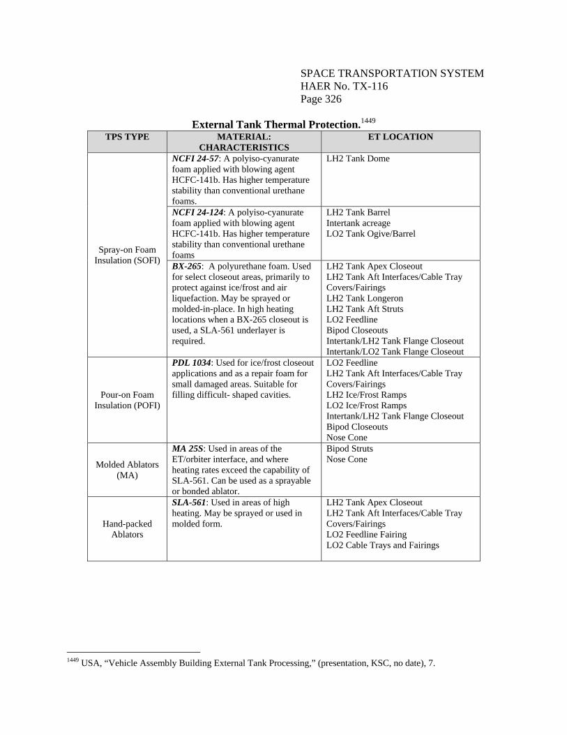
SPACE TRANSPORTATION SYSTEM HAER No. TX-116 Page 326
External Tank Thermal Protection.1449
TPS TYPE MATERIAL: CHARACTERISTICS
ET LOCATION
Spray-on Foam Insulation (SOFI)
NCFI 24-57: A polyiso-cyanurate foam applied with blowing agent HCFC-141b. Has higher temperature stability than conventional urethane foams.
LH2 Tank Dome
NCFI 24-124: A polyiso-cyanurate foam applied with blowing agent HCFC-141b. Has higher temperature stability than conventional urethane foams
LH2 Tank Barrel Intertank acreage LO2 Tank Ogive/Barrel
BX-265: A polyurethane foam. Used for select closeout areas, primarily to protect against ice/frost and air liquefaction. May be sprayed or molded-in-place. In high heating locations when a BX-265 closeout is used, a SLA-561 underlayer is required.
LH2 Tank Apex Closeout LH2 Tank Aft Interfaces/Cable Tray Covers/Fairings LH2 Tank Longeron LH2 Tank Aft Struts LO2 Feedline Bipod Closeouts Intertank/LH2 Tank Flange Closeout Intertank/LO2 Tank Flange Closeout
Pour-on Foam Insulation (POFI)
PDL 1034: Used for ice/frost closeout applications and as a repair foam for small damaged areas. Suitable for filling difficult- shaped cavities.
LO2 Feedline LH2 Tank Aft Interfaces/Cable Tray Covers/Fairings LH2 Ice/Frost Ramps LO2 Ice/Frost Ramps Intertank/LH2 Tank Flange Closeout Bipod Closeouts Nose Cone
Molded Ablators (MA)
MA 25S: Used in areas of the ET/orbiter interface, and where heating rates exceed the capability of SLA-561. Can be used as a sprayable or bonded ablator.
Bipod Struts Nose Cone
Hand-packed Ablators
SLA-561: Used in areas of high heating. May be sprayed or used in molded form.
LH2 Tank Apex Closeout LH2 Tank Aft Interfaces/Cable Tray Covers/Fairings LO2 Feedline Fairing LO2 Cable Trays and Fairings
1449 USA, “Vehicle Assembly Building External Tank Processing,” (presentation, KSC, no date), 7.
SPACE TRANSPORTATION SYSTEM HAER No. TX-116 Page 327
The ET derived its distinctive color from the insulating foam. When first applied, the foam was light tan in color. Then, exposure to ultraviolet rays darkened or reddened the foam over time.1450 SOFI is a low-density, closed-cell foam which was used on the tank acreage to keep the propellants at optimum temperature while preventing a buildup of ice on the outside of the tank. It is a polyurethane-type foam composed of five primary ingredients: polymeric isocyanate, a flame retardant, a surfactant, a blowing agent, and a catalyst.1451 The SOFI was applied over the SLA when both highly efficient insulation and high heating capability were required.1452 The larger sections of the tank were covered in NCFI 24-124. This SOFI type accounted for 77 percent of the total foam used on the ET. NCFI 24-57 was used on the aft dome of the LH2 tank. Both NCFI 24-124 and NCFI 24-57 were mechanically sprayed foams. PDL 1034, a hand-poured foam, was used for filling odd-shaped cavities. BX 265 foam was manually applied, or hand-sprayed, in the closeout areas, and applied mechanically on the feedlines and domes inside of the intertank.1453 The SLA is a denser composite material made of silicone resins and cork that dissipates heat by eroding. It was used on areas that were subjected to extreme heat, including the aft dome and the cable trays. The ablator thickness was defined primarily by the ascent mission phase.1454 MA25S, a high temperature ablator, was developed by Lockheed Martin. During the application process, TPS materials were subject to the formation of small voids caused by encapsulated air in the foam. This was especially the case around uneven areas, such as joints. To reduce the likelihood for voids, strict process controls for both automated and manual foam applications were implemented. Typically, foam was hand-applied around complicated areas.1455 Interface Hardware The ET contained hardware for attachment and interface with the two SRBs, the orbiter, and with the ground launch facilities. The interfaces were both structural connections to the other stack elements, as well as umbilicals for the transfer of fluids and electrical power. The ET/SRB
1450 Steve Roy, “Last Shuttle External Tank Rolling Out on July 8,” July 7, 2010, http://www.nasa.gov/connect/chat/last_tank_rollout2.html. 1451 The surfactant controlled the surface tension of a liquid, and thus, cell formation. “The blowing agent, HCFC 141b, created the foam’s cellular structure by making millions of tiny bubbles or foam cells.” NASA MSFC, Thermal Protection System. 1452 Lockheed Martin, Handbook (SLWT), 11-2. 1453 Closeouts were TPS applications conducted after final assembly and checkout; a minimum number were made at the launch site. They were most critical on areas where the insulation was applied on surfaces subjected to cryogenic temperatures. Lockheed Martin, Handbook (SLWT), 11-2. 1454 Lockheed Martin, Handbook (SLWT), 11-2. 1455 NASA, Implementation Plan, 1-1.
SPACE TRANSPORTATION SYSTEM HAER No. TX-116 Page 328
interfaces included four structural attach points plus electrical connections, per SRB. Of these, one forward attach point was located on the intertank, and three attach points were fitted on the aft LH2 tank section. The ET/orbiter interfaces included one forward and two aft connections. A ground facility interface, located at the intertank, provided ground services to purge the intertank and to actuate vent valves for prelaunch operations. In addition, the ET included interface provisions for the connection to transportation and handling support equipment. ET/SRB Interfaces The structural interfaces between the ET and the two SRBs consisted of eight attachment points, four on each side (left and right) of the ET. These included two forward interfaces (left and right) for SRB attachment and thrust transmission, and six aft stabilization interface points (three left and three right). The latter were connected to the ET aft major ring frame. In addition, two ET/SRB electrical interfaces (left and right) were located on the aft top stabilization struts. All ET/SRB interface attachment hardware was SRB-provided and consisted of a frangible bolt at each of the forward interfaces, and a shear pin at each of the aft strut/tank interfaces.1456 The two identical ET/SRB forward thrust interfaces consisted of permanently fixed, 5”-radius spherical seats machined from AMS-5629 corrosion-resistant stainless steel, and housed in large machined/forged 7050 aluminum alloy thrust fittings. Each of the thrust fittings weighed approximately 400 pounds. An SRB-provided frangible bolt was installed through each fitting. The thrust fittings also included provisions for attachment of the ET forward hoisting fittings. The six ET/SRB aft structural attachments included upper top, upper bottom, and lower attachments, each with a left and a right. Each fitting, made from annealed titanium alloy (Ti6AL4V) castings, was attached to the ET major ring frame by shear pins and tension bolts. The upper fitting (top and bottom) measured 7” wide at the base, was 26” in length, and weighed approximately 75 pounds. It was attached to the ring frame with eight 3/4”-diameter and six 5/8”-diameter tension bolts, a 3-3/4”-diameter shear pin, and a shaped key. The lower fitting measured 6.5” wide at the base, was 19” in length, and weighed approximately 50 pounds. It was configured similar to the upper fitting, featuring a monoball interface with the SRB stabilization strut. Each of the 3.25”-diameter monoballs was manufactured of Inconel 718. Each lower fitting was attached to the aft major ring frame with twelve 3/4”-diameter tension bolts, a 2”-diameter shear pin, and a 1” x 0.5” platform key.1457 ET/orbiter Interfaces ET/orbiter structural interfaces included two aft-positioned points located at the ET aft major ring frame and the LH2 tank longerons, as well as a forward attachment supported from the LH2 tank forward ring frame. The right aft support was a tripod, making it fixed. The other two 1456 Lockheed Martin, Handbook (SLWT), 12-6. 1457 Lockheed Martin, Handbook (SLWT), 12-9 through 12-11.
SPACE TRANSPORTATION SYSTEM HAER No. TX-116 Page 329
interfaces were bipods, with the left aft permitting lateral pivot motion and the forward allowing fore/aft motion. All ET/orbiter structural interface attachment hardware was orbiter-provided, and consisted of a frangible bolt and hex nut at the forward interface, and a frangible nut and tension bolt at each of the two aft points. Fluid and electrical interfaces were located at two aft umbilical assemblies, positioned adjacent to the two aft structural interfaces. These two umbilical assemblies, supported by brackets, consisted of clustered disconnects that mated with the ET fluid lines and electrical cables.1458 The ET/orbiter Forward Attachment hardware was a bipod weighing approximately 190 pounds. It was canted at 0.5 degrees forward when mated to the orbiter. The primary elements of the forward attachment were the identical left and right struts, the yoke fitting, the upper end and lower end fittings, and the spindle assembly. The latter, comprised of operating mechanisms within a titanium housing, provided attachment of the struts to the LH2 tank forward ring frame structure.1459 The two hollow, aluminum struts measured 60” long and featured flanges on each end. The orbiter end of the left strut was attached to a yoke fitting that mated with the orbiter. The yoke fitting was a large machined titanium (Ti-6AL4V) casting that formed a 74 degree apex angle between the two struts, and which encased the orbiter-provided frangible bolt. The ET end of both struts was flanged identically to mate with the flanged lower end fitting. One end fitting was cast titanium and the other was Inconel 718.1460 The ET/orbiter Aft Left Attachment hardware consisted of a bipod structure. When the tank was unloaded, the bipod was canted 18 degrees inboard. The structure was attached to the orbiter by an orbiter-housed 2.5”-diameter tension bolt coupled with a frangible nut. The components of the aft left structure included a ball interface fitting, thrust strut, thrust strut end fitting, vertical strut, vertical strut end fitting, and vertical strut tank fitting. The ball interface fitting, made of forged 7050 aluminum alloy, weighed approximately 530 pounds. It joined the thrust and vertical struts. The thrust strut, also of 7050 aluminum alloy, was 120” long, with a 16.6” inner diameter. The thrust strut end fitting, made of 2219 aluminum, was connected to the LH2 tank left longeron by a 4”-diameter stainless steel shear pin inserted through a 5-3/4”-diameter stainless steel monoball. The approximately 60”-long vertical strut, of 7050 aluminum alloy, was connected to the ball interface fitting by a 4”-diameter steel shear pin. Sixteen 7/8”-diameter steel tension bolts connected the vertical strut to the 2219 aluminum strut end fitting. The vertical strut tank fitting was made of titanium (Ti-6AL4V) casting. Six 5/8”-diameter and four 7/8”-diameter steel bolts, and a 3-3/4”-diameter integral shear pin attached the fitting to the ring frame.1461 The ET/orbiter Aft Right Attachment was a tripod structure. It originated from two points on the aft major ring frame and from the forward end of the right longeron. The aluminum ball
1458 Lockheed Martin, Handbook (SLWT), 12-15. 1459 Lockheed Martin, Handbook (SLWT), 12-17. 1460 Lockheed Martin, Handbook (SLWT), 12-18. 1461 Lockheed Martin, Handbook (SLWT), 12-19, 12-20.
SPACE TRANSPORTATION SYSTEM HAER No. TX-116 Page 330
interface fitting, which weighed 530 pounds, was a near mirror image of the aft left fitting. The thrust strut-to-ball interface fitting, the thrust struts, and the vertical struts, also were near identical.1462 The ET/orbiter Crossbeam was a rectangular-shaped aluminum structure measuring 176” long. It was comprised of extruded channel sections and integral forgings welded together to form a single assembly. It was bolted to the right ball interface fitting by twenty-four 5/8”-diameter bolts. The right end of the crossbeam contained two bulkhead forgings that supported the LO2 feedline elbow; the left end contained two integral bulkhead forgings that provided the attachment for the LH2 feedline hinge brackets.1463 The ET, like the orbiter, had half of the 17” LH2 feedline disconnect that served as the structural support for an umbilical assembly. This assembly contained the 2” GH2 pressurization line disconnect, the 4” recirculation line disconnect, and pullaway ET/orbiter and orbiter/SRB electrical disconnects, all mounted in a single cluster plate. This plate was mechanically attached to the ET side of the interface.1464 The right umbilical assembly was similar to the left assembly, except for the absence of the 4” fluid disconnect. With the ET mated to the orbiter, the disconnect halves were held together by 2-1/4”-diameter umbilical separation system bolts. ET/Ground Facilities Interfaces The ET intertank was equipped with fluid and electrical interfaces with the ground facility pressurization, vent and electrical systems. The umbilical system consisted of a hardline subassembly which terminated with a GUCA. The GUCA interfaced with the ET intertank carrier plate assembly (ETCA). Each of these carrier assemblies contained their respective sections of the disconnect component for the electrical or gas system. A pyrotechnic bolt attached the GUCA to the ETCA.1465 ET Process Flow Throughout the SSP, all ETs were built, assembled, and acceptance tested by contractor Lockheed Martin Space Systems Company at NASA’s MAF in New Orleans, Louisiana, then transported by barge to KSC for inspections, integration with the orbiter and SRBs, and launch. A summary of this process follows.
1462 Lockheed Martin, Handbook (SLWT), 12-21. 1463 Lockheed Martin, Handbook (SLWT), 12-22. 1464 Lockheed Martin, Handbook (SLWT), 12-24, 12-25. 1465 Lockheed Martin, Handbook (SLWT), 12-33, 12-34.
SPACE TRANSPORTATION SYSTEM HAER No. TX-116 Page 331
Manufacture and Assembly According to Mark Bryant, vice president of the External Tank Program for Lockheed Martin Space Systems, the length of time required to build a tank was affected by several factors. Generally, the LWT used to take about two years to build, while the SLWT with the post-Columbia modifications and process controls took more than three years, start to finish.1466 Overview The components of the ET were manufactured in Building 103 at MAF (Figure No. D-29). The process began with three concurrent manufacturing and assembly tracks – one for the LO2 tank, one for the intertank, and one for the LH2 tank. The LO2 tank and intertank were combined in Cell J of Building 114; the LH2 tank and the LO2 tank/intertank were assembled into the finished ET in Cell A of Building 110.1467 Pressure testing of both propellant tanks was conducted in Building 110 and Structure 451. The ET components were cleaned and sprayed in Buildings 110, 114, and 131, and ablator was applied to elements of the ET in Building 318. Final approval and purchase of the ET by NASA took place in Building 420.1468 The manufacturing approach for the LO2 tank and LH2 tank assemblies entailed welding structural components into subassemblies such as domes, ogives and barrels, and then performing mechanical, propulsion, and electrical system installations at the subassembly level, to the extent possible. After completion of these processes, each tank was proof tested.1469 Next, the LH2 tank was cleaned, iridited,1470 primed and mated to the intertank to form the LO2/intertank stack and TPS application was completed. The LO2/intertank stack was joined to the LH2 tank in the vertical attitude and TPS closeout was performed. The mated ET assembly was then moved to the horizontal final assembly area for completion.1471 LO2 Tank Assembly The LO2 ogive nose section was fabricated in two sections: forward and aft. The forward section consisted of eight gore panels and a forward ring fitting. The eight gores were welded in a vertical trim and weld fixture, first into four quarter panels, and then into two half-body assemblies, and finally into one assembly. The forward ring fitting was welded on next. All
1466 Roy, “External Tank.” 1467 M. Todd Cleveland, Evaluation of Resources Associated with the Space Shuttle Program, Michoud Assembly Facility, New Orleans, Louisiana (survey report, MAF, TRC, May 2007), 19. 1468 Cleveland, Evaluation of Resources, 19. 1469 Proof testing was done to screen for critical flaws in the structure. It was performed on each LH2 tank and LO2 tank to demonstrate the strength of each tank pressure wall to 113 percent or greater of the limit load. Ryan, “Aerospace Problems.” 1470 Iridite is a chemical film which provides a barrier medium to prevent corrosion on aluminum surfaces, and enhances adhesion of paints and primers. 1471 Lockheed Martin, Handbook (SLWT), 14-2.
SPACE TRANSPORTATION SYSTEM HAER No. TX-116 Page 332
edges were custom-trimmed prior to welding. The aft ogive section consisted of twelve gore panels. The operations were the same as for the forward ogive, except there was no forward fitting. Four extruded segments comprised the T-frame which made the transition from ogive section to barrel section. These were welded together in a trim and weld fixture. The four pre-formed panels which formed the barrel section were welded together.1472 Fabrication of the LO2 dome began with the dome gore/gore welded assembly. The longitudinal abutting edges of the gore panels were saw-trimmed and welded. The completed quarter panel and the mating chord abutting edges were trimmed and welded. Next, the abutting edges of the quarter panel-chord assemblies were welded to produce a half dome body. The two half dome assemblies were brought together and the abutting edges trimmed and welded together to form a dome body. The completed dome body was then routed to the dome body/cap weld fixture for welding into a completed dome. The dome cap was welded to the dome body in a rim and weld fixture. Both the dome body and the dome cap were trimmed, then welded together on the dome body/cap weld fixture.1473 The LO2 forward slosh baffle individual ring segments and truss assemblies were joined, and then fabricated into a three-level baffle assembly. The LO2 tank major weld was accomplished in a horizontal rotational weld fixture. The major tank components were welded together from forward to aft. The slosh baffle was installed into the ogive/barrel assembly prior to welding on the aft dome. Next, the aft dome weld, which was the tank closeout weld, was made using an expanding mandrel. The completed LO2 tank was proof tested in the hydrostatic test facility using demineralized water to which a chromate corrosion resistant solution was added (Figure No. D-30). A vacuum was drawn on the aft dome to provide the required proof pressure gradient. After proof testing, the LO2 tank was X-rayed, then routed for cleaning and TPS application.1474 Intertank Assembly The structural assembly of the intertank began with the splicing of the intermediate and main frame 90 degree segments into 180 degree segments. The 180 degree frame segments were loaded and aligned into a half section tack station along with the three stringer panels. Here, approximately 409 of the total panel to frame fasteners were installed. The panel to panel butt splices were tack fastened and the rollties were installed. The intertank -Z half section was positioned on the automatic riveter and the +Z half section was started on the tack section station. While on the automatic riveter, the remaining panel to frame butt splice fasteners were drilled and installed. The -Z half section was then moved to the finish/inspect station where the fasteners, installed by the automatic riveter, were inspected, and all systems substructure was installed. Operations were repeated for the +Z half section. Splice details and closure panels for the SRB beam were pre-drilled in a pre-assembly fixture. The pre-aligned SRB beam was placed
1472 Lockheed Martin, Handbook (SLWT), 14-2. 1473 Lockheed Martin, Handbook (SLWT), 14-2, 4-3. 1474 Lockheed Martin, Handbook (SLWT), 14-3.
SPACE TRANSPORTATION SYSTEM HAER No. TX-116 Page 333
in the assembly fixture. The half sections were then loaded in, and their frames spliced at the +Y axis. Thrust panels were then installed. Longeron tie ins and thrust panel butt straps and rollties were installed. The forward and aft interface flange holes patterns also were drilled. After removal of the intertank from the assembly fixture, it was placed in a fixture for installation of propulsion and electrical systems. The intertank was then moved to Cell G or H for SOFI application to the sidewalls using an automotive gun spray system. After completion of SOFI rim operations, the intertank was moved to Cell J for LO2 tank stacking.1475 LH2 Tank Assembly The LH2 forward and aft domes were fabricated in the same manner as the LO2 dome. The LH2 aft barrel section was welded. The three LH2 forward barrel sections were welded in a horizontal barrel weld fixture (Figure No. D-31). The panels were sequentially loaded and welded. The three LH2 T-ring frames were welded in the same fixture used for the LO2 T-ring. The LH2 tank major weld was accomplished in a horizontal rotational weld fixture similar to that used for the LO2 tank. The LH2 tank assembly sequence began with the loading of the aft dome into the weld fixture followed by the loading of the aft barrel section. After the mating edges had been prepared, the circumferential weld was made. The remaining barrel sections and ring frames that comprised the LH2 tank were prepared and welded in like manner. The welded assembly, less the forward dome, was then removed from the fixture and loaded into another fixture where X-rays and mechanical installations were performed. The assembly was then moved to another fixture where the final circumferential weld of the LH2 tank was made between the forward dome and the forward barrel section. Welding of the forward dome to the barrel section completed the LH2 tank assembly (Figure No. D-32). The completed LH2 tank was then routed to proof test, which combined a pneumatic GN2 pressure test with a hydraulic local test. While the tank was pressurized, loads were applied to simulate the loads from the SRBs and the orbiter. Completion of the proof test was followed by a leak test, then transport to Building 103 for proof X-ray operations.1476 TPS Application After completion of proof testing and X-rays, the LO2 tank was cleaned and iridited internally and cleaned externally. Internal installations were made, welds were iridited and external surfaces primed, and SOFI was then applied to the aft dome using an automated sprayer. The LO2 tank was then mated and spliced to the intertank, the LO2 feedline was mechanically hooked-up, the feedline brackets were installed, and SLA handpack operations were performed (Figure No. D-33). The LO2/intertank stack underwent an automated application of SOFI, and mechanical installations were performed. Closeout/trim of flange and cable tray brackets was completed and the LO2 stack was ready for mating to the LH2 tank.
1475 Lockheed Martin, Handbook (SLWT), 14-3. 1476 Lockheed Martin, Handbook (SLWT), 14-4.
SPACE TRANSPORTATION SYSTEM HAER No. TX-116 Page 334
After proof testing and X-ray, the LH2 tank was cleaned, primed, and covered with an application of TPS. The first steps were external cleaning, prime and mechanical installations. The LH2 tank was then internally cleaned and iridited. Internal installations in the aft dome were completed, followed by the application of SOFI to the barrel section areas and the forward dome. SLA panels were bonded to the apex aft dome area, and then SOFI was applied to the aft dome. Next, the LH2 tank was mated with the LO2 tank/intertank assembly (Figure No. D-34), and TPS closeout of the splice area was performed. SRB attachment fittings were installed and alignments were verified prior to final assembly, performed in Building 103. This entailed the installation of electrical and mechanical hardware, including feedline, cable tray, interface hardware, and electrical wiring, as well as ET/orbiter interface hardware. TPS closeouts followed.1477 Test and checkout, performed in Building 420, started with a wiring integrity test, followed by mechanical joint leak tests, subsystem testing, and finally, an All Systems Test which simulated the flight profile (Figure No. D-35). Pack and ship activities also were completed in Building 420. Next, the LO2 and LH2 tanks were purged with GN2, and pressurized to 6 psig with dry GN2 prior to shipment.1478 Transportation and Delivery Each completed ET was loaded onto the covered barge Pegasus at MAF (Figure No. D-36), then towed to Gulfport, Mississippi, where retrieval ship Liberty Star or Freedom Star joined the barge to make the approximate 900 mile journey to KSC (Figure No. D-37).1479 It typically took about seven to ten days for the tank to travel through the Mississippi River, out to and across the Gulf of Mexico, then up through the Straits of Florida to Cape Canaveral, through the port, up the Banana River, and on to the Barge Terminal Facility at KSC located near the VAB (Figure No. D-38).1480 At KSC, each ET was offloaded from the barge (Figure No. D-39) and moved atop a transporter to the transfer aisle of the VAB (Figure No. D-40). The ET was rotated to vertical (Figure No. D-41), and placed in a checkout cell for visual inspection by a team of engineers, technicians and quality inspectors. While in the checkout cell, the ground umbilical carrier plate was installed and the aft hardpoint TPS closeout was performed. Nitrogen, which filled both the LH2 and LO2 tanks, was replaced with helium, mainly to keep moisture out and to allow for pressure monitoring. Propulsion system leak checks and limited electrical checks were performed, as well as a pneumatics checkout to make sure the valves were functioning properly.1481 The umbilicals
1477 Lockheed Martin, Handbook (SLWT), 14-5. 1478 Lockheed Martin, Handbook (SLWT), 14-5. 1479 There were instances when a chartered ship was used to pull the barge instead of a SRB retrieval ship when the ships were engaged in other operations. Bartolone, interview. 1480 Bartolone, interview. 1481 Lockheed Martin, Handbook (SLWT), 3-3.
SPACE TRANSPORTATION SYSTEM HAER No. TX-116 Page 335
located on the bottom end of the ET, built by Boeing as matched sets to the orbiters, were balanced, adjusted, repaired (if necessary), and prepared for orbiter mate by a Boeing team.1482 Normal processing in the check-out cell took about eighteen days. After verification of ET integrity, the transport equipment and instrumentation were removed, and the ET was hoisted by a large overhead crane (Figure No. D-42) and moved to the VAB integration cell (High Bay 2 or 4) for storage prior to stacking. The ET was lifted out of the high bay via overhead crane and moved into High Bay 1 or 3 for mating. Integration and Launch After the SRBs were stacked on the MLP in VAB High Bay 1 or 3, the ET was lowered into position and mated to the SRBs (Figure No. D-43). The ET/SRB forward support fittings were attached, followed by mating and securing of the aft fittings. All ET/SRB interface system connections were made. Next, the orbiter was moved into the integration cell and attached to the ET at one forward attachment point and two aft points. The orbiter was rotated forward and jacked into final position for attachment to the ET bipod. Umbilicals between the ET and orbiter were connected. Following the move of the complete Space Shuttle vehicle from the VAB to the launch pad, facility servicing lines were mated through the ET intertank carrier plate assembly. The facility LO2 and LH2 systems were purged, and both ET tanks were purged with helium to assure an inert atmosphere for propellant loading.1483 At T-5 hours and 50 minutes, the launch processing system initiated the SSME LH2 chill-down sequence in preparation for LH2 loading. Both propellants were loaded simultaneously, starting with a slow flow rate to precondition the lines, tanks, and engines. At the 2 percent level, the flow rates were increased to a maximum of 12,000 gallons per minute for LH2 and 5,000 gallons per minute for LO2 until 98 percent capacity was reached. The flow rate was reduced again to provide a topping flow rate to 100 percent capacity, followed by a still slower replenish rate to maintain 100 percent propellant levels. This flow continued until the automatic sequence started at T-9 minutes.1484 Vapors from each propellant were vented during the loading and conditioning process. The fuel system purge began at T-4 minutes. At T-2 minutes and 55 seconds the LO2 tank was pressurized to 221 psi, and almost one minute later, the LH2 tank was pressurized to 42 psi. At T-9.5 seconds, the engine chill-down sequence was complete. The main fuel valve and the main oxidizer valve in each engine were opened. Between the time of valve opening and MECO, LH2 and LO2 flowed out of the ET through the disconnect valves, and into the feedline manifolds, from where they were distributed to the engines.
1482 Bartolone, interview. 1483 Lockheed Martin, Handbook (SLWT), 3-4. 1484 Lockheed Martin, Handbook (SLWT), 3-5.
SPACE TRANSPORTATION SYSTEM HAER No. TX-116 Page 336
The ET fed approximately 535,000 gallons of LO2 and LH2 propellants to the three SSMEs during the first 8.5 minutes of flight, at a rate of 1,035 gallons per second.1485 The ET was jettisoned within ten to fifteen seconds after MECO, at an altitude of about 70 miles (Figure No. D-44). Separation of the ET from the orbiter was initiated by the firing of a pyrotechnic valve located in the nose cap that broke the attachment hardware links.1486 Following separation, the residual LO2 contained in the tank was gasified, which imparted a tumbling action to the ET. Tumbling provided for better fragmentation and a more predictable area of impact. The ET broke up into fragments as it fell back to Earth. Almost the entire tank burned up during re-entry. Any debris that did not burn fell into a predetermined area of the Pacific or Indian Ocean.
1485 Lockheed Martin, “Statistics and Comparisons.” 1486 NASA KSC, “Lightweight External Tank.”