Parametric Hull Form Optimization for a Wind Farm ... · PDF file•CAESES geometry...
29
Transcript of Parametric Hull Form Optimization for a Wind Farm ... · PDF file•CAESES geometry...
Parametric Hull Form Optimization for a Wind Farm Installation Vessel
Harry Linskens
Hans van der Tas
CAESES European Users’ Meeting
29-09-2017
WHO IS DEKCHISTORY
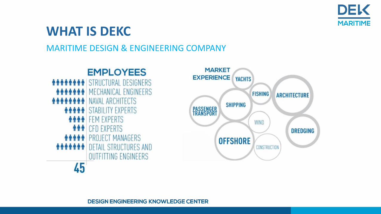
WHAT IS DEKCMARITIME DESIGN & ENGINEERING COMPANY
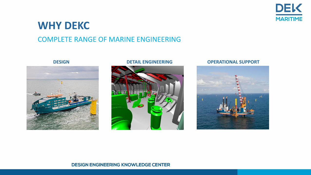
DESIGN OPERATIONAL SUPPORTDETAIL ENGINEERING
WHY DEKCCOMPLETE RANGE OF MARINE ENGINEERING
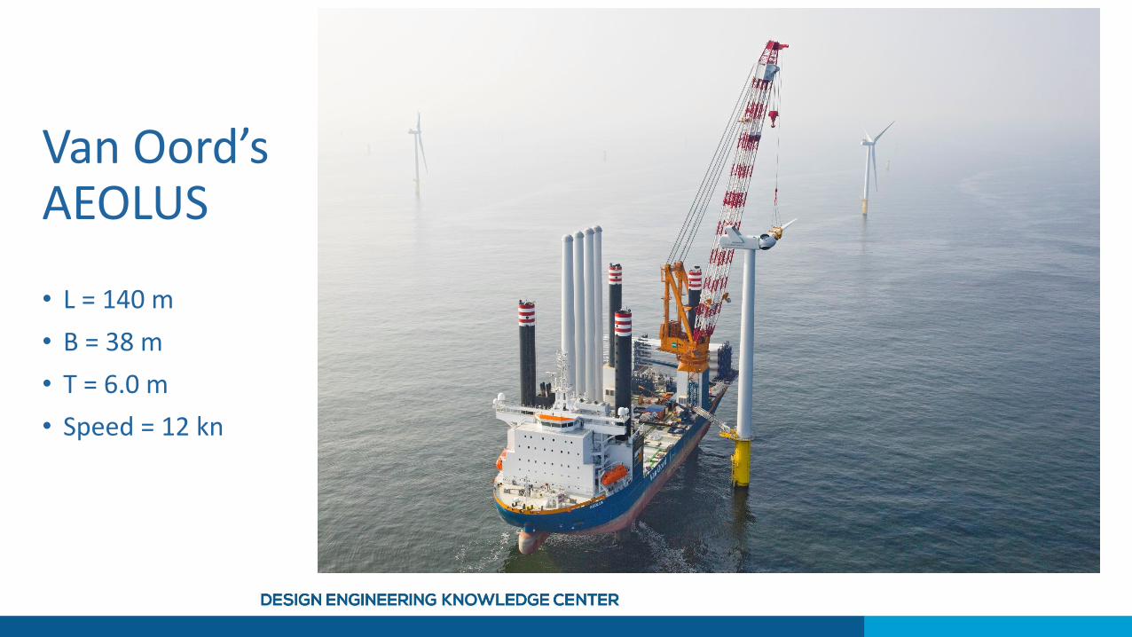
Van Oord’sAEOLUS
• L = 140 m
• B = 38 m
• T = 6.0 m
• Speed = 12 kn
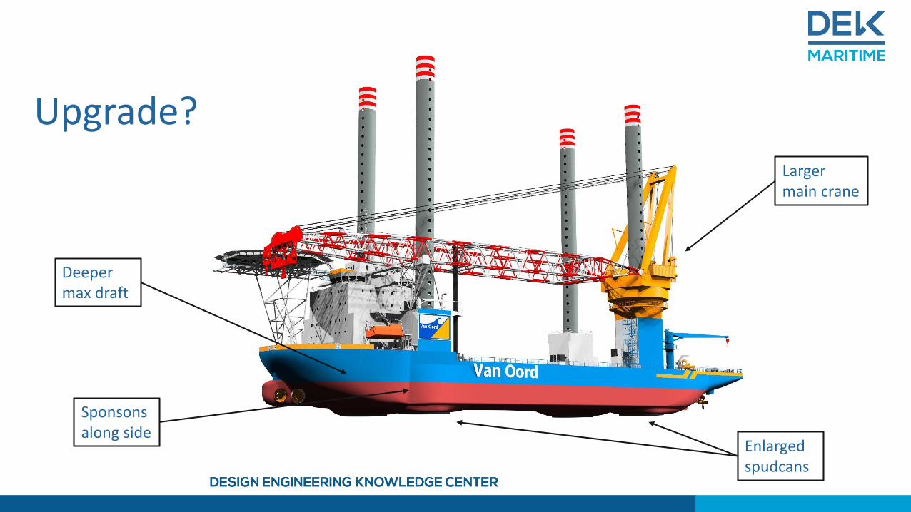
Upgrade?
Enlarged spudcans
Sponsons along side
Larger main crane
Deeper max draft

AEOLUS 2.0
• L = 140 m
• B = 44 m
• T = 6.6 + 2.0 m
• No changes to propulsion or powerplant
• Speed = ??? kn

Topics for today
• Project outline
• Geometry modeling
• Optimization
• Results
Project Outline
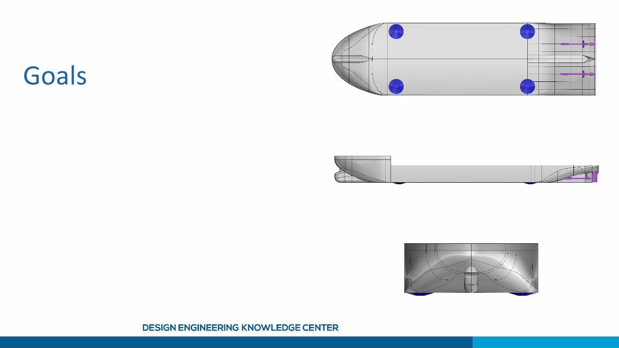
Goals
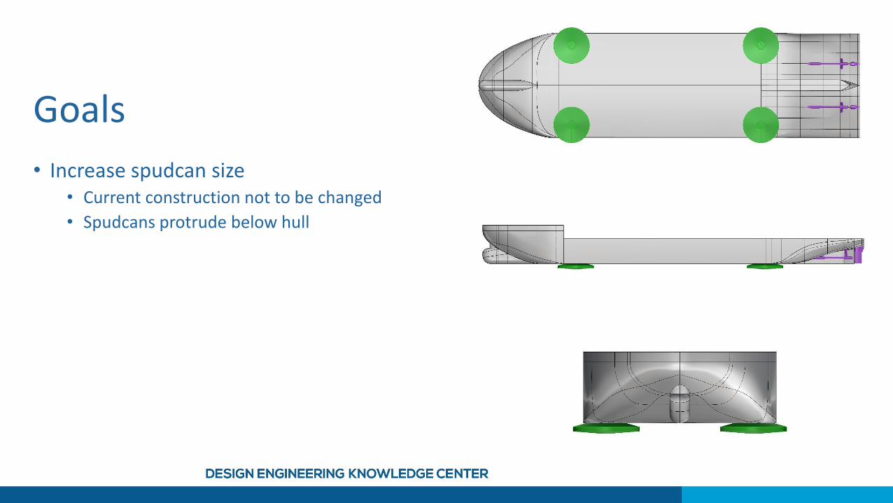
Goals
• Increase spudcan size• Current construction not to be changed
• Spudcans protrude below hull
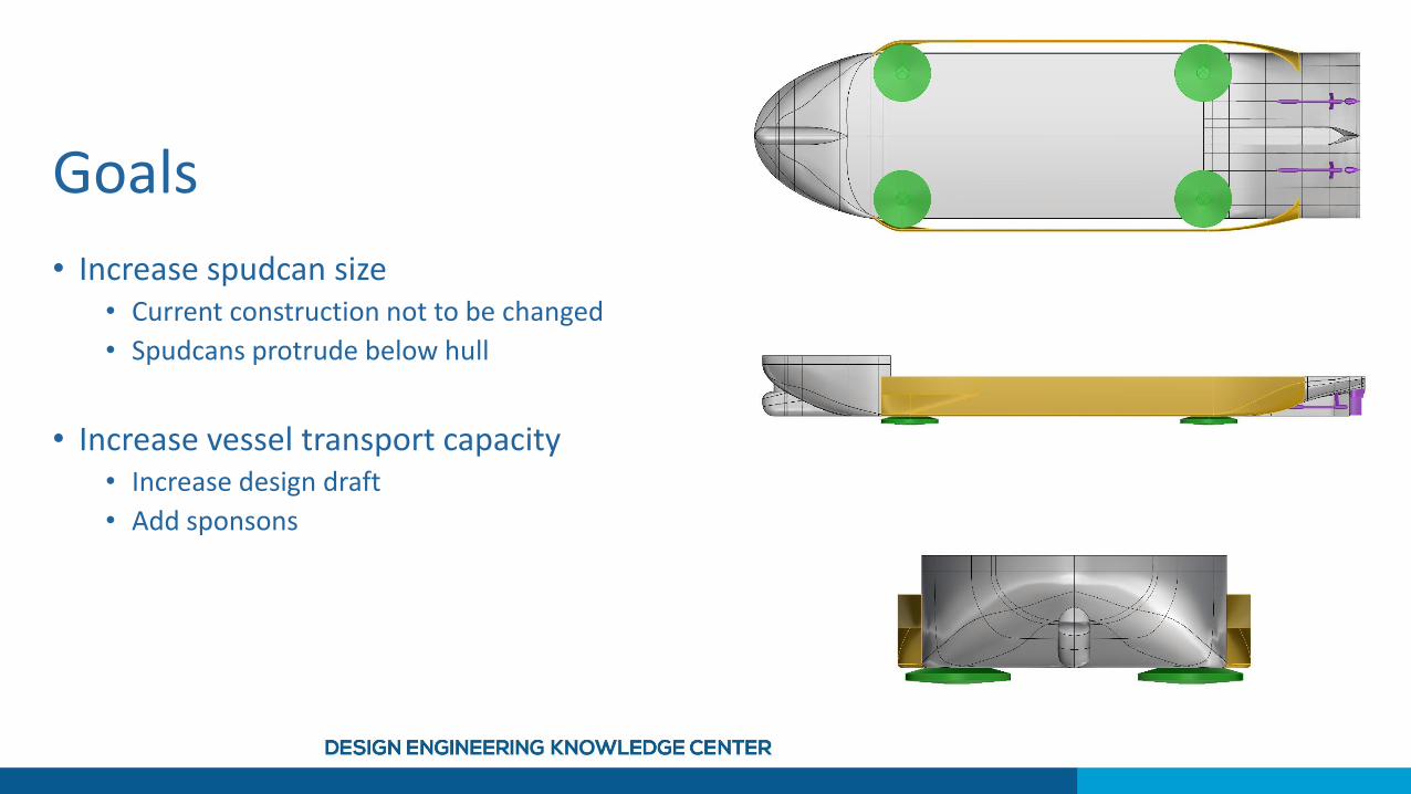
Goals
• Increase spudcan size• Current construction not to be changed
• Spudcans protrude below hull
• Increase vessel transport capacity• Increase design draft
• Add sponsons
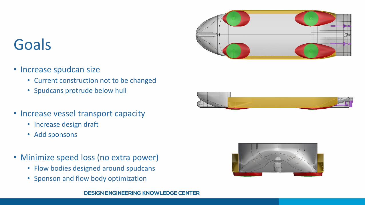
Goals
• Increase spudcan size• Current construction not to be changed
• Spudcans protrude below hull
• Increase vessel transport capacity• Increase design draft
• Add sponsons
• Minimize speed loss (no extra power)• Flow bodies designed around spudcans
• Sponson and flow body optimization
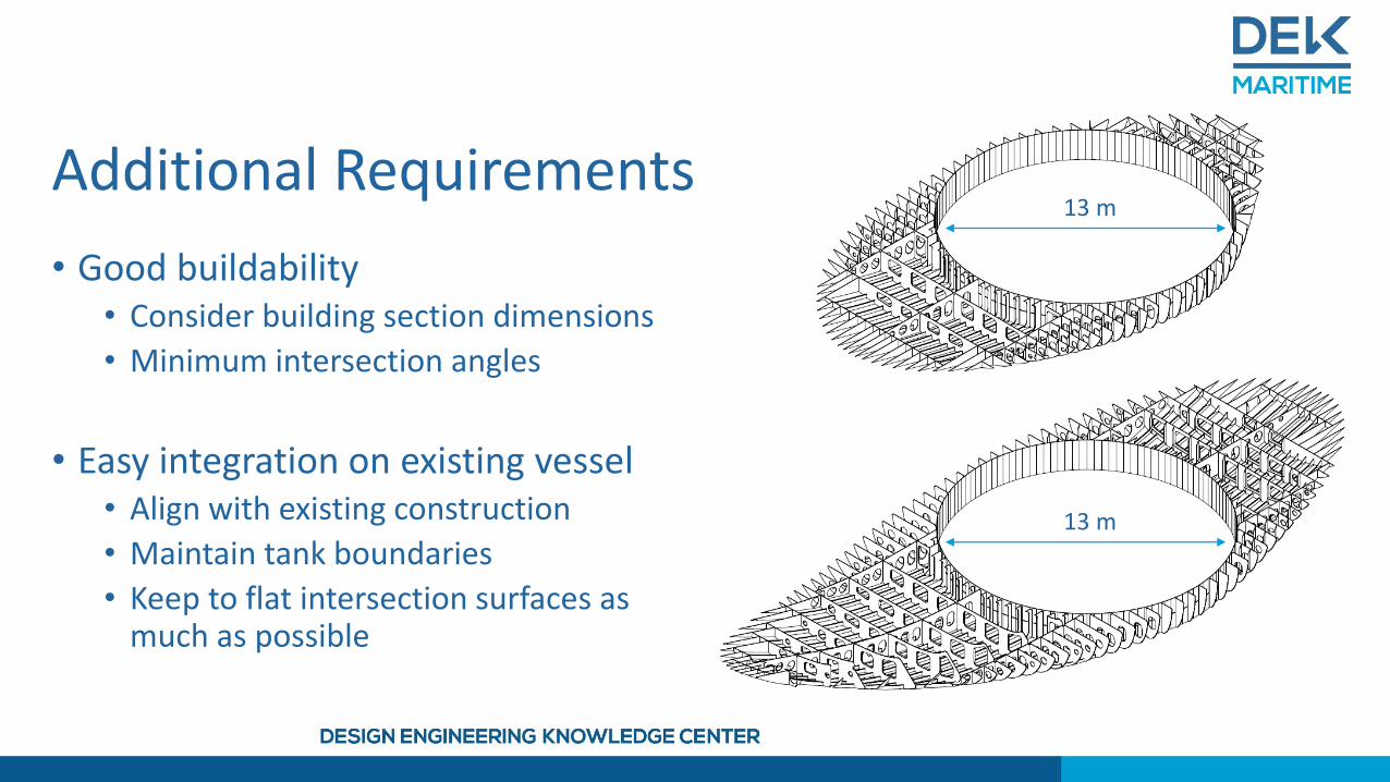
Additional Requirements
• Good buildability• Consider building section dimensions
• Minimum intersection angles
• Easy integration on existing vessel• Align with existing construction
• Maintain tank boundaries
• Keep to flat intersection surfaces as much as possible
13 m
13 m
Geometry Modeling
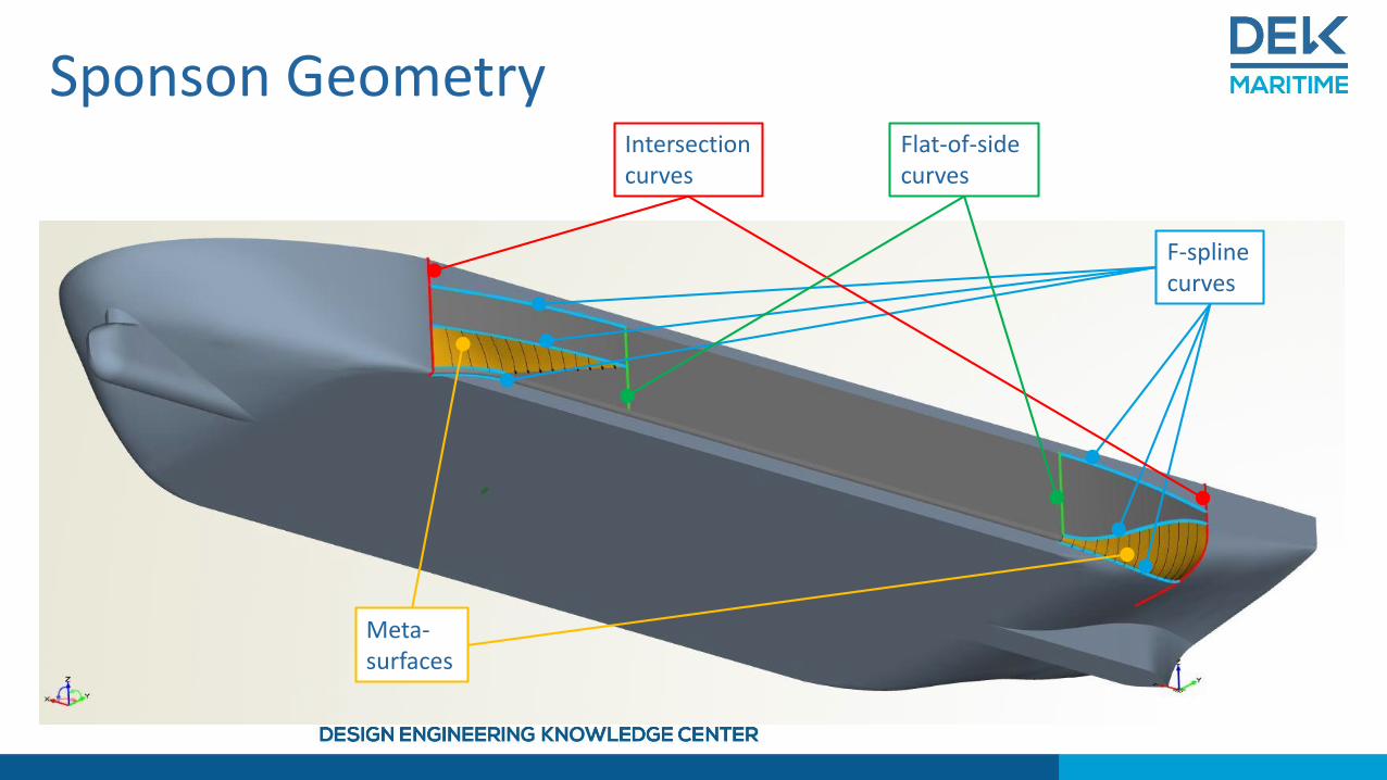
F-spline curves
Intersection curves
Meta-surfaces
Flat-of-side curves
Sponson Geometry
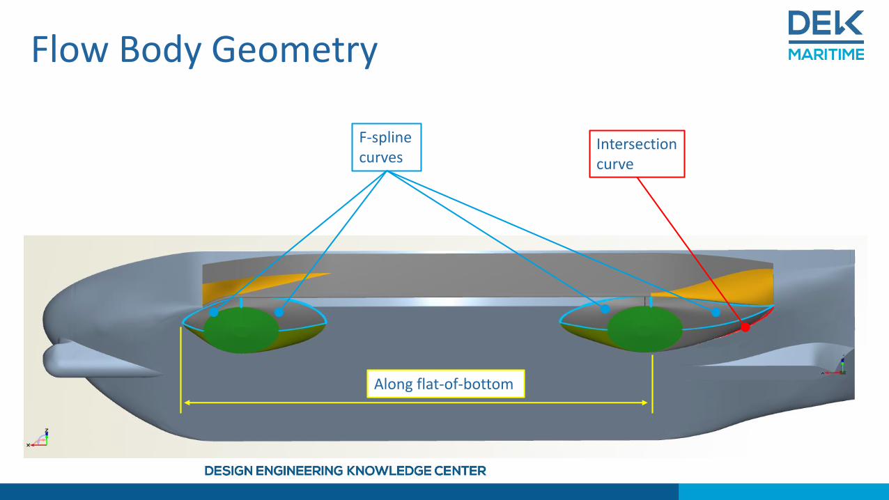
F-spline curves
Intersection curve
Along flat-of-bottom
Flow Body Geometry
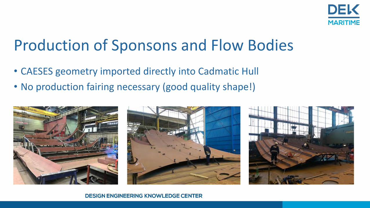
Production of Sponsons and Flow Bodies
• CAESES geometry imported directly into Cadmatic Hull
• No production fairing necessary (good quality shape!)
Optimization
Global Strategy
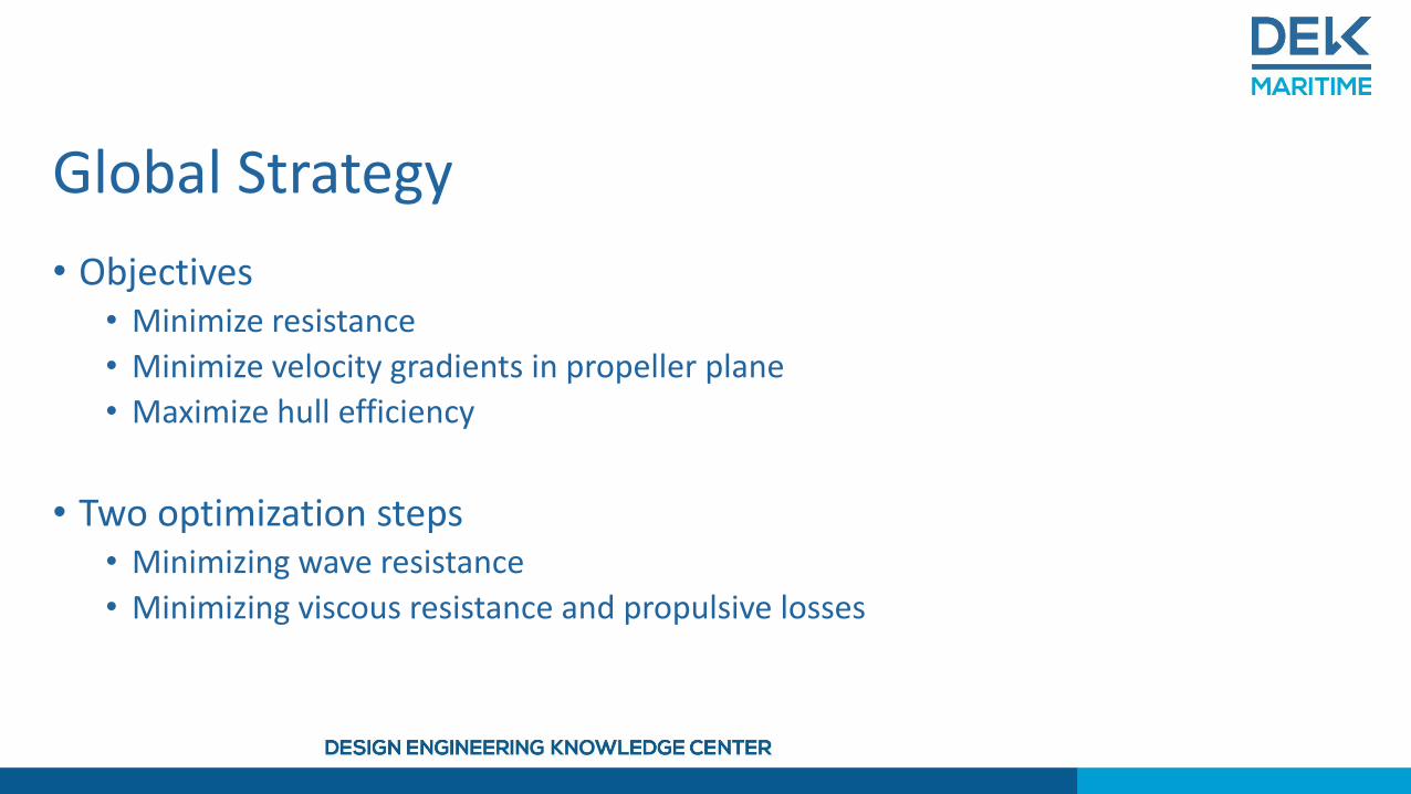
• Objectives• Minimize resistance
• Minimize velocity gradients in propeller plane
• Maximize hull efficiency
• Two optimization steps• Minimizing wave resistance
• Minimizing viscous resistance and propulsive losses
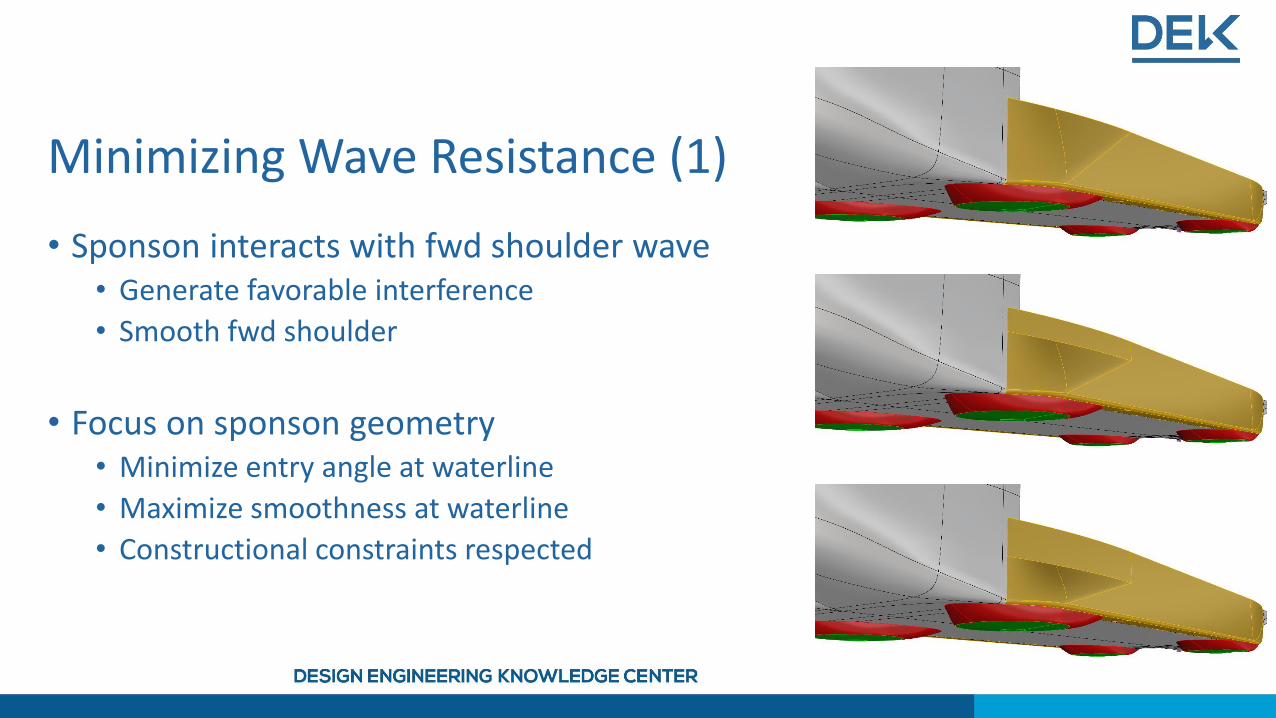
Minimizing Wave Resistance (1)
• Sponson interacts with fwd shoulder wave• Generate favorable interference
• Smooth fwd shoulder
• Focus on sponson geometry• Minimize entry angle at waterline
• Maximize smoothness at waterline
• Constructional constraints respected
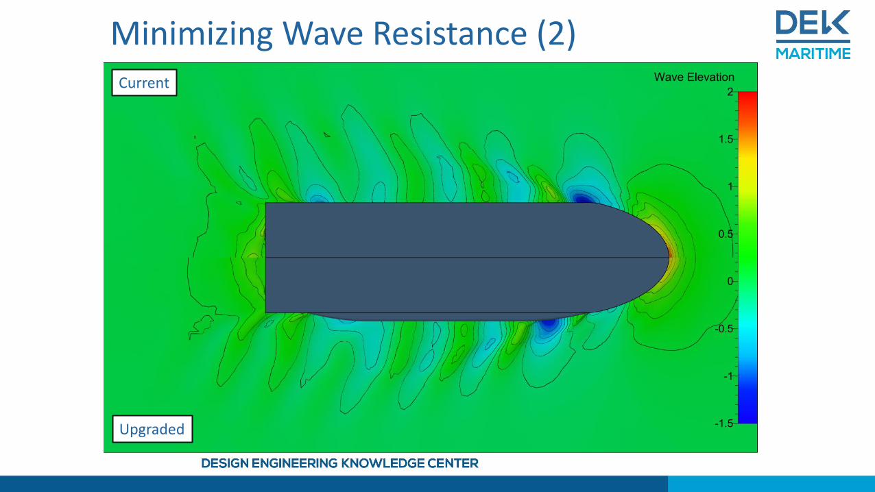
Minimizing Wave Resistance (2)Current
Upgraded

• Parametrized sponson and flow body models
• Two-stage multi-objective optimization• Global optimization using Sobol
• Local optimization using Tsearch
• Software connection from CAESES to Numeca FINE/Marine
Minimizing Viscous Losses (1)
STL domain,Optimization routine
Resistance,Wake
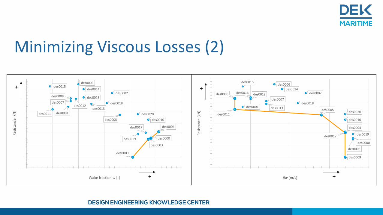
Minimizing Viscous Losses (2)
des0000
des0001
des0002
des0003
des0004
des0005
des0006
des0007
des0008
des0009
des0010
des0011
des0012
des0013
des0014
des0015
des0016
des0017
des0018
des0019
des0020
388
390
392
394
396
398
400
402
404
0.45 0.50 0.55 0.60 0.65
Res
ista
nce
[kN
]
δw [m/s] +
+
des0000
des0001
des0002
des0003
des0004
des0005
des0006
des0007
des0008
des0009
des0010
des0011
des0012des0013
des0014des0015
des0016
des0017
des0018
des0019
des0020
388
390
392
394
396
398
400
402
404
0.0990 0.1000 0.1010 0.1020 0.1030 0.1040 0.1050
Res
ista
nce
[kN
]
Wake fraction w [-] +
+
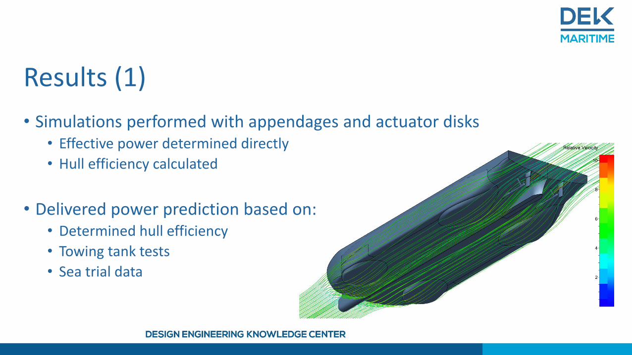
Results (1)
• Simulations performed with appendages and actuator disks• Effective power determined directly
• Hull efficiency calculated
• Delivered power prediction based on:• Determined hull efficiency
• Towing tank tests
• Sea trial data
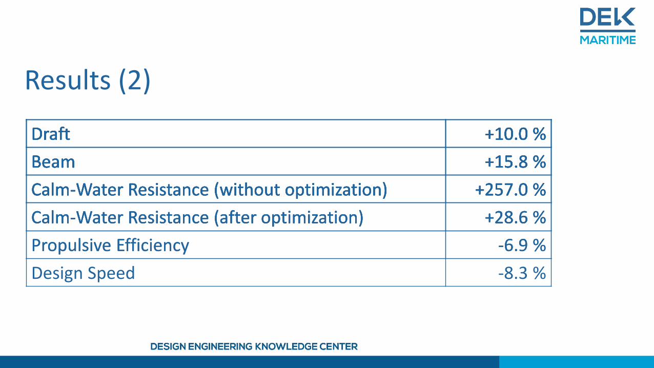
Results (2)
Draft +10.0 %Draft +10.0 %
Beam +15.8 %
Draft +10.0 %
Beam +15.8 %
Calm-Water Resistance (without optimization) +257.0 %
Draft +10.0 %
Beam +15.8 %
Calm-Water Resistance (without optimization) +257.0 %
Calm-Water Resistance (after optimization) +28.6 %
Draft +10.0 %
Beam +15.8 %
Calm-Water Resistance (without optimization) +257.0 %
Calm-Water Resistance (after optimization) +28.6 %
Propulsive Efficiency -6.9 %
Draft +10.0 %
Beam +15.8 %
Calm-Water Resistance (without optimization) +257.0 %
Calm-Water Resistance (after optimization) +28.6 %
Propulsive Efficiency -6.9 %
Design Speed -8.3 %
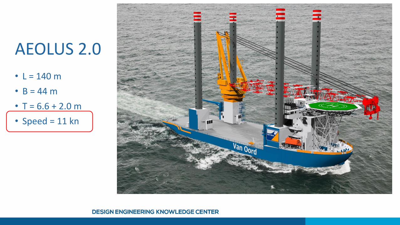
AEOLUS 2.0
• L = 140 m
• B = 44 m
• T = 6.6 + 2.0 m
• Speed = 11 kn


![[14.08.18] Convex Hull Trick](https://static.fdocument.pub/doc/165x107/54663fd9af79595d038b4c5e/140818-convex-hull-trick.jpg)