Pandora · 2019-02-12 · Pandora begins to scan and transmit data automatically once it is powered...
44
Pandora All-in-One Sensing Solution for Autonomous Driving User’s Manual HESAI Wechat www.hesaitech.com 100-en-1801A2
Transcript of Pandora · 2019-02-12 · Pandora begins to scan and transmit data automatically once it is powered...

PandoraAll-in-One Sensing Solution for Autonomous Driving User’s Manual
HESAI Wechat
www.hesaitech.com100-en-1801A2
yamagiwa
スタンプ

Caution
To avoid violating the warranty and to minimize the chances of getting electrically shocked, please do not disassemble the device on your own accord. The device must not be tampered with and must not be changed in anyway. There are no user-serviceable parts inside the device. For repairs and maintenance inquiries, please contact an authorized Hesai Technologies service personnel.
Use of controls or adjustments or performance of procedures other than those specified herein may result in hazardous radiation exposure
CAUTION
The device satisfies the requirements of: IEC 60825-1:2014; 21 CFR 1040.10 and 1040.11 except for deviations pursuant to Laser Notice No.50, dated June 24, 2007; GB7247.1-2012
Laser Safety Notice-Laser Class 1
DISCLAIMER The information contained within this user’s manual and the functions offered are intended to provide information about products. All reasonable efforts have been made to ensure the accuracy of the information. However, Hesai cannot be held responsible for any errors. Hesai does not warrant the accuracy and reserves the right to make changes to the catalog and its functions at any time without notice.
Please read and follow all instructions carefully and consult all relevant national and international safety regulations for your application.
Safety Notice

Contents
1.1
1Pandora-LiDAR 02-03
1.2 Pandora-Camera 04
1.3 Camera and LiDAR Synchronization and Calibration 05
1.4 Specifications 06
Introduction
2.1 Mechanical Installation 07
2.2 Interfaces 08
2.3 How to Connect 09-10
Installation2
3.1 LiDAR Data Structure 11-18
3.2 Camera Data Structure 19-20
3.3 Analysis of Data 20
3.4 Pandora Projection for ROS 20
Pandora Data Structure3
4.1 Open Web Control 21
4.2 Setting 22
4.3 Device Info 23
4.4 Firmware Upgrade 24
Web Control4
25-26
Appendix ILiDAR Channel Distribution
27-30
Appendix IIPoint Cloud Data Packet Absolute Time and Laser Firing Time Calculations
31-38
Appendix IIIPandarView
39-40
Appendix IVSupport and Contact

Figure 1.1 Placement of Pandora
LiDAR
LiDAR has an extended measurement range of 200m at 20% reflectivity, and generates up to 720,000 data points per second
Cameras
Four wide-angle lens cameras and one forward-facing color camera capture 360° image around the car
Introduction1
Pandora is an all-in-one sensor kit for environment sensing for self-driving cars. It integrates cameras, LiDAR and data processing ability into the same module, with advanced synchronization and calibration solutions.
In addition to the specifications of Pandora, this manual also describes the mechanical installation, data outputs format, and GPS timestamp synchronization.
This manual is undergoing constant revision and improvement, please ask Hesai for the lastest version of the user’s manual.
- 0 1 -

The upside of Pandora is a 40-channel mechanical LiDAR. It creates 3D image by 360° rotating through 40 laser diodes inside the housing. LiDAR’s unique channel distribution makes it more suitable for autonomous driving applications.
1.1 Pandora — LiDAR
1.1.1 Operational Principles
Distance Measurement: Time of Flight (ToF)
Figure 1.2 ToF Formula
d= ct12
d:c:t :
DistanceSpeed of lightLaser beam travel time
A laser diode emits a beam of ultrashort pulse laser on to the object.Diffuse reflection of the laser occurs upon contact with the target object. Reflected beams are detected by the optical sensor.Distance to object can be accurately measured by calculating the time between emission and receipt by the sensor.
1.2.
3.
1.1.2 Structure Description
40 pairs of laser emitters and receivers are attached to a rotating motor inside the Pandora that perform horizontal scans in 360 degrees.
Laser ReceiverLaser Emitter Shell
Interface
Figure 1.3 Partial Cross-Sectional Diagram
- 0 2 -

Channel 1
Channel 6
Channel 12
Channel 30
Channel 40
+ 7°
+ 2°
0°
- 6°
- 16°
Figure 1.4 LiDAR Channel Distribution
1.1.3 Channel Distribution
The vertical angular resolution is 0.33° between Channel 6 and Channel 30;The vertical angular resolution is 1° between Channel 1 and Channel 6, Channel 30 and Channel 40.Please see Appendix I for detailed channel distribution.
- 0 3 -
Camera
Black and White:129° Color:52°
LiDAR
360°
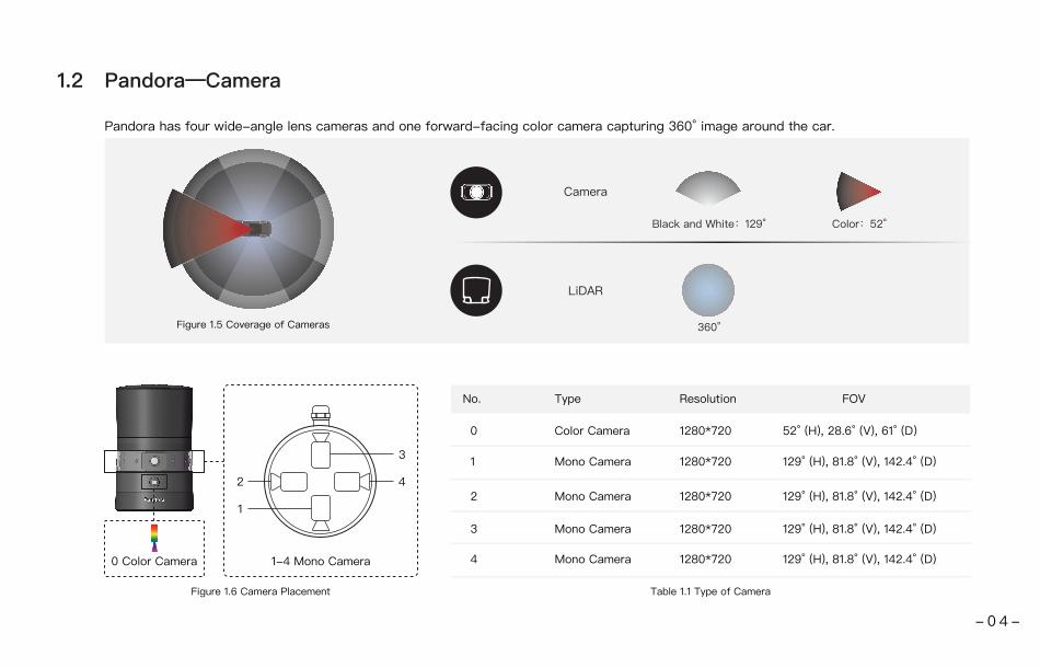
Pandora has four wide-angle lens cameras and one forward-facing color camera capturing 360° image around the car.
Figure 1.5 Coverage of Cameras
Figure 1.6 Camera Placement
No. Type Resolution FOV
0 Color Camera 1280*720 52° (H), 28.6° (V), 61° (D)
1 Mono Camera 1280*720 129° (H), 81.8° (V), 142.4° (D)
2 Mono Camera 1280*720 129° (H), 81.8° (V), 142.4° (D)
3 Mono Camera 1280*720 129° (H), 81.8° (V), 142.4° (D)
4 Mono Camera 1280*720 129° (H), 81.8° (V), 142.4° (D)
Table 1.1 Type of Camera
3
1
2 4
0 Color Camera 1-4 Mono Camera
Pandora—Camera1.2
- 0 4 -

Figure 1.7 Synchronization of LiDAR and Cameras Figure 1.8 Calibration of Multiple Sensors
Synchronization
Pandora controls the motor rotating and laser firing time of the LiDAR, and at the same time, LiDAR controls the exposure time and frame rate of the cameras. Therefore, Pandora can achieve synchronization of point cloud data from LiDAR and imaging data from the cameras, which makes sure those data are describing the same object.
Exposure
Exposure
Calibration
Based on the calibration between point cloud and images, an accurate mapping between point cloud and camera pixel can be achieved and their spaces can be accurately matched.
Camera and LiDAR Synchronization and Calibration1.3
- 0 5 -

Specifications1.4
LiDAR
Scanning Method Mechanical Rotating
Channel 40
Measurement Range 0.3 m~200 m(20% reflectivity)
Accuracy ±5 cm (0.3 m ~ 0.5 m), ±2 cm (0.5 m ~ 200 m)
Point Frequency 720 kHz
Laser Class Class 1 Eye Safety
Frame Rate 10 Hz, 20 Hz
FOV (Horizontal) 360°
Angular Resolution 0.2°(10 Hz), 0.4°(20 Hz),
FOV (Vertical) -16°~7°
Return Mode Dual Return
Angular Resolution (Vertical) 0.33°(-6° to +2°);1°(-16° to -6°,+2° to +7°)
Color Camera
Resolution 1280*720
FOV 52°(H), 28.6°(V), 61°(D)
EFL 5.47 mm
TV-Distortion <-14.2%
Mono Camera
Resolution
FOV
1280*720
129° (H), 81.8° (V), 142.4° (D)
EFL 1.65 mm
TV-Distortion <-44.2%
System Specs
Size Height: 190 mm, Top Diameter: 116 mm, Bottom Diameter: 118 mm
Power Consumption 30 W
Data Transmission Ethernet (1000 Mbps)
Operating Temperature -10 ℃~60 ℃
Operating Voltage 9 V~32 V
Weight 2.1 kg
Enclosure Level IP66
Table 1.2 Pandora Specifications
- 0 6 -

Pandora has already finished calibration before delivery. The unit is easy to install and plug-and-play. Please refer to chapter 2 for details on mechanical dimension, interfaces and connection methods.
NOTE Because of the intrinsic angle offset of each laser channel, the zero degree is defined as the azimuth angle in the corresponding block in UDP packet when channel 12 passes y axis defined in figure 1.3.
Installation2
Mechanical Installation2.1
45°
φ118(0D)
2-φ4mm 5.5mm
FORφ4mm PINS
φ88.9 5-M6 5(MOUNT)
φ118
Figure 2.1 Mechanical Dimension Figure 2.2 Pandora Rotation Direction
270°
90°
180° 0°
Clockwise Rotation Direction
Reference Center
- 0 7 -

Interfaces2.2
Power Light
a b c d e
GPS port pin number from left to right is 1 to 6, and the specific definition of each pin is shown as follows:
Table 2.2 GPS Pin No. DescriptionTable 2.1 Interface Description
Figure 2.3 Pandora Interfaces
Pin No.
1 InputPPS synchronizing signal, to receive synchronized pulses from the GPS module, TTL 3.3V
2 Output 5V power, to provide power for external GPS module
3 Output GND, to ground external GPS module
4 InputReceiving signal of serial port, receiving serial data from external GPS module, RS232 level
5 Output GND, to ground external GPS module
6 NC Not connected
Direction Pin Description
c Standard Ethernet Port
RJ45, 1000 Mbps Ethernet
d, e Reserved Interfaces
a GPS Port
Connector type: JST SM06B-SRSS-TBRecommended connector for external GPS module: JST SHR-06V-S-BVoltage standard: RS232Baud rate: 9600 bps
bb Power PortPower Port
Use DC-005 DC power adapter.Input voltage ranges from 9 V to 32 V. Power consumption is 30 W
- 0 8 -

GND, to ground external GPS module
How to Connect2.3
Connection of Pandora2.3.1
Pandora begins to scan and transmit data automatically once it is powered up and connected to the computer.Web control can be used to set parameters of Pandora before using. For more on web control, see Chapter 4. Users can use PandarView to quickly view or record point cloud data captured by Pandora. For more on PandarView installation and usage, see Appendix III PandarView.
Pandora
Power Port and Standard Ethernet Port
Connecting BoxComputer
Connect the power port to the adapter
Use an Ethernet cable to connect the LiDAR’s and computer’s Ethernet ports.
Figure 2.4 How to Connect
- 0 9 -

IP Configuration2.3.2
To receive data on your PC, please set the PC IP address to 192.168.20.100.
Windows: 1) Open the Network Sharing Center, click on “Ethernet”. 2) In the “Ethernet Status” interface, click on “Properties” to proceed to the next interface.3) Double-click on “Internet Protocol Version 4 (TCP/IPv4)”4) Configure the IP address to 192.168.20.100 and subnet mask to 255.255.255.0, then click “OK” to finish configuration.
Ubuntu-16.04:The IP address can be configured on the terminal by using the ifconfig command:~$ sudo ifconfig enp0s20f0u2 192.168.20.100Replace enp0s20f0u2 with the local network port name.
- 1 0 -

LiDAR Data Structure3.1
The communication protocol for data output of LiDAR is Gigabit Ethernet UDP/IP. The output data includes Point Cloud Data Packet and GPS Data Packet. Each data packet consists of an Ethernet Header and UDP Data.
Figure 3.1 Data Structure of LiDAR
LIDAR Data
Point Cloud Data Pachet
Ethernet Header:42 bytes
UDP Data:1262 bytesRanging Data:1240 bytes
Additional Information:22 bytes
GPS Data PachetEthernet Header:42 bytes
UDP Data:512 bytes
Users can receive both point cloud data from LiDAR and imaging data from cameras through Ethernet Cable. The data communication protocol for LiDAR is UDP protocol, while that for camera is TCP protocol.
Pandora Data Structure3
- 1 1 -

Here is an example of the definition of Ethernet Header:
A Pandora has a unique MAC address. The destination IP address is 0xFF and in broadcast form. The default source IP address is 192.168.20.51. Taking “Internet Protocol (20 bytes)” as an example, it is described as follows:
Ethernet Header: 42 bytes
Table 3.1 Definition of Point Cloud Data Packet Ethernet Header
Ethernet II MAC
Ethernet Data Packet Type
Internet Protocol
UDP Port Number
UDP Length and Checksum
12 bytes
2 bytes
20 bytes
4 bytes
4 bytes
Destination: Broadcast (0xFF: 0xFF: 0xFF: 0xFF: 0xFF: 0xFF), Source: (xx:xx:xx:xx:xx:xx)
0x08, 0x00
Version, Header Length, Differentiated Services Field, Total Length, Identification, Flags, Fragment Offset, Time to Live, Protocol, Header Checksum, Source IP Address, Destination IP Address
UDP source port (0x2710, represents10000), destination port (0x0940, represents 2368)
Length 2 bytes (0x04F6, represents 1270 bytes), checksum 2 bytes
Figure 3.2 Point Cloud Data Packet Ethernet Header Internet Protocol
Point Cloud Data Packet—— Ethernet Header
3.1.1 Point Cloud Data Packet
Each Point Cloud Data Packet has a 42 bytes Ethernet Header and 1262 bytes UDP Data.
- 1 2 -
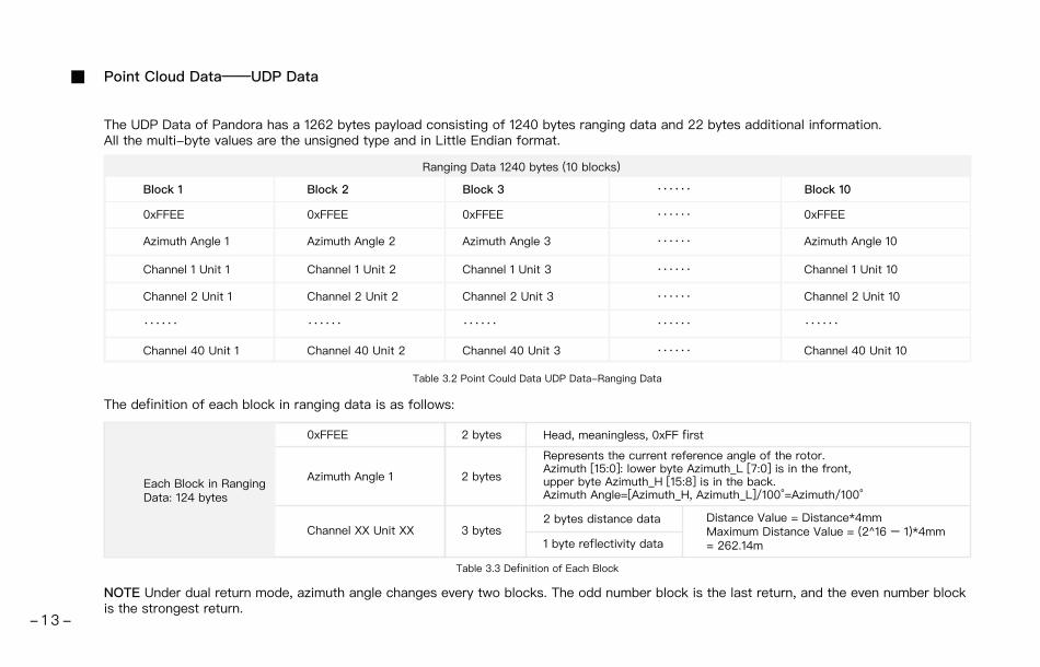
The UDP Data of Pandora has a 1262 bytes payload consisting of 1240 bytes ranging data and 22 bytes additional information.All the multi-byte values are the unsigned type and in Little Endian format.
The definition of each block in ranging data is as follows:
NOTE Under dual return mode, azimuth angle changes every two blocks. The odd number block is the last return, and the even number block is the strongest return.
Table 3.3 Definition of Each Block
Table 3.2 Point Could Data UDP Data-Ranging Data
Ranging Data 1240 bytes (10 blocks)
Block 1 Block 2 Block 3 Block 10
0xFFEE 0xFFEE 0xFFEE 0xFFEE
Azimuth Angle 1 Azimuth Angle 2 Azimuth Angle 3 Azimuth Angle 10
Channel 1 Unit 1 Channel 1 Unit 2 Channel 1 Unit 3 Channel 1 Unit 10
Channel 2 Unit 1 Channel 2 Unit 2 Channel 2 Unit 3 Channel 2 Unit 10
Channel 40 Unit 1 Channel 40 Unit 2 Channel 40 Unit 3 Channel 40 Unit 10
······ ······ ······ ······
······
······
······
······
······
······
······
Each Block in Ranging Data: 124 bytes
0xFFEE 2 bytes Head, meaningless, 0xFF first
Azimuth Angle 1 2 bytes
Represents the current reference angle of the rotor. Azimuth [15:0]: lower byte Azimuth_L [7:0] is in the front, upper byte Azimuth_H [15:8] is in the back.Azimuth Angle=[Azimuth_H, Azimuth_L]/100°=Azimuth/100°
Channel XX Unit XX 3 bytes2 bytes distance data Distance Value = Distance*4mm
Maximum Distance Value = (2^16 – 1)*4mm = 262.14m1 byte reflectivity data
Point Cloud Data——UDP Data
- 1 3 -

Additional Information: 22 bytes
Table 3.4 Point Cloud Data UDP Data-Additional Information
Reserved 8 bytes reserved data, meaningless
Motor Speed 2 bytes speed_2_bytes [15:0] = speed (RPM)
GPS Timestamp 4 bytes the packing time of this data packet, the unit is 1 μs, value range 0 μs-1 s
Return Mode Information 1 byte the strongest return (0x37), the last return (0x38), dual return (0x39)
Factory Information 1 byte 0x42 (or 0x43)
UTC 6 bytes year, month, date, hour, minute, second, decimal digit
Taking Channel 5 in block 3 of a UDP Data Packet as an example, please see Appendix I for detailed channel distribution:
1)
2)
3)
By now, the direction and distance of this point have been decided, and this obstacle point could be drawn in the polar or rectangular
coordinate system. The real-time point cloud data can be drawn by analyzing every data in the UDP Data Packet using the above method.
Horizontal angle offset of the laser is -2.50°, and vertical angle of the laser is 3.00° for Channel 5.
Horizontal angle is the current reference angle of the rotor plus horizontal angle offset, so the result is (Azimuth Angle 3+(-2.50)) degree.
(NOTE We define clockwise as a positive direction of the angle from top view)
Analyze the “Channel 5 Unit 3” from the UDP Data Packet, and the distance formed by upper 2 bytes multiplied by 4mm is the actual
distance in millimeters in the real world.
Example of UDP Data Analysis
- 1 4 -

3.1.2 GPS Data Packet Ethernet Header/ UDP Data
Each GPS Data Packet has a 42 bytes Ethernet Header and 512 bytes UDP Data, and the port is 10110. Before receiving the GPS module data, the rising edge of the internal 1Hz signal of Pandora will trigger a GPS Data Packet. GPS time data will be counted from 000101000000 (yymmddhhmmss, year, month, day, hour, minute, second) and GPRMC information is not available at this time.
After the GPS module data has been sent to Pandora, the local 1 Hz signal of Pandora will be locked at PPS signal. The rising edge of the internal 1Hz signal will trigger a GPS Data Packet. Meantime, the GPS time data will be reset to actual GPS time and GRPMC information will be the original data sent by GPS module.
If GPS module stops sending data, Pandora will still trigger a GPS Data Packet following the internal 1Hz signal. GPS time data will be counted on the base of previously actual GPS time.
Ethernet Header: 42 bytes
Table 3.5 Definition of GPS Data Packet Ethernet Header
Ethernet II MAC 12 bytes
2 bytes
20 bytes
4 bytes
4 bytes
Destination: Broadcast (0xFF: 0xFF: 0xFF: 0xFF: 0xFF: 0xFF), Source: (xx:xx:xx:xx:xx:xx)
0x08, 0x00
Version, Header Length, Differentiated Services, Field, Total Length, Identification, Flags, Fragment Offset, Time to Live, Protocol, Header Checksum, Source IP Address, Destination IP Address
UDP source port (0x2010, represents 10000), destination port (0x277E, represents 10110)
Length 2 bytes (0x208, represents 520 bytes), checksum 2 bytes
Ethernet Data Packet Type
Internet Protocol
UDP Port Number
UDP Length and Checksum
GPS Data Packet – Ethernet Header
Here is the definition of GPS Data Packet Ethernet Header:
- 1 5 -

The destination IP address is 0xFF and in broadcast form. The default source IP address is 192.168.20.51. Taking “Internet Protocol (20 bytes)” as an example, it is described as follows:
GPS Data Packet - UDP Data
Figure 3.3 GPS Data Packet Ethernet Header Internet Protocol Illustration
UDP Data of GPS Data Packet consists of 18 bytes time data and 494 bytes additional information. All the multi-byte values are the unsigned type and in Little Endian format.
Table 3.6 GPS Data Packet-UDP Data Definition
GPS UDP data: 512 bytes
GPS Time Data 18 bytes
GPRMC Data 77 bytes ASCII code, valid till 2 bytes after ‘*’
Filled with 411 0xDF
From GPRMC information, ASCII code, A=valid, V=invalid
1=locked, 0=unlocked
Reserved meaningless data
Reserved Data 411 bytes
Location valid or not 1 byte
Flag of PPS lock 1 byte
Reserved Data 4 bytes
Header
Date
Time
μs Time
2 bytes
6 bytes
6 bytes
4 bytes
0xFFEE
Year month and day in order (2 bytes each), lower byte first, ASCII code
Second minute and hour in order (2 bytes each), lower byte first, ASCII code
Unit is μs, lower byte first
- 1 6 -

Date:Year: 0x37, 0x31, convert ASCII code to '7', '1'; means 17Month: 0x32, 0x31, convert ASCII code to '2', '1'; means 12Day: 0x30, 0x32, convert ASCII code to '0', '2'; means 20
Figure 3.4 GPS Data Packet UDP Data Illustration
Time:Second: 0x32, 0x35, convert ASCII code to '2', '5'; means 52Minutes: 0x35 0x34 convert ASCII code to '5’, '4; means 45Hour: 0x32 0x31, convert ASCII code to '2', '1'; means 12 (UTC time)
μs Time:4 bytes, the μs time value of each GPS PPS pulse, and timestamp will be set as 0 μs.The μs time of GPS PPS and the timestamp from the point cloud data have the same data source, and the unit is 1 μs.
Example of GPS Data Packet UDP Data Analysis
- 1 7 -

GPRMC Data Format:
the standard GPRMC data format is as follows:
$GPRMC, <1>, <2>, <3>, <4>, <5>, <6>, <7>, <8>, <9>, <10>, <11>, <12>*hh,
Detailed descriptions are as follows:
The GPS interface of Pandora is compatible with a variety of data formats. The external GPS module GPRMC data format needs to meet the
following conditions:
the data in <01> is the hour, minute, and second information; the data in <09> is the date information.
The following two formats are both admissible:
1) $GPRMC,072242,A,3027.3680,N,11423.6975,E,000.0,316.7,160617,004.1,W*67
2) $GPRMC,065829.00,A,3121.86377,N,12114.68322,E,0.027,,160617,,,A*74
<01> UTC Time, hhmmss (hour, minute, second) format
<02> Location Status, A=Valid Position, V=Invalid Position
<03> Latitude ddmm.mmmm (degree, minute) format
<04> Latitude Northern (N) or Southern (S) Hemisphere
<05> Longitude dddmm.mmmm (degree, minute) format
<06> Longitude Eastern (E) or Western (W) Hemisphere
<07> Ground Rate (000.0 to 999.9 knots)
<08> Ground Direction (000.0 ~ 359.9 degrees, referencing true north)
<09> UTC Date, ddmmyy (day, month, year) format
<10> Declination (000.0 to 180.0 degrees)
<11> Declination Direction, E (east) or W (west)
<12> Mode (only on version NMEA0183 3.00, A=Automatic Positioning,
D=Differential, E=Estimation, N=Invalid Data)
- 1 8 -
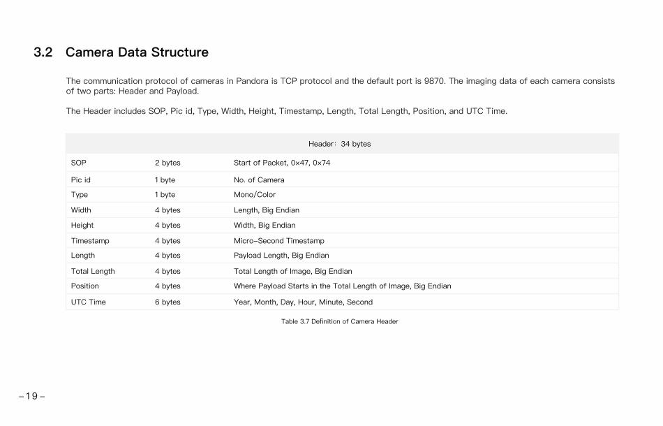
3.2 Camera Data Structure
The communication protocol of cameras in Pandora is TCP protocol and the default port is 9870. The imaging data of each camera consists of two parts: Header and Payload.
The Header includes SOP, Pic id, Type, Width, Height, Timestamp, Length, Total Length, Position, and UTC Time.
Header:34 bytes
Table 3.7 Definition of Camera Header
SOP 2 bytes
1 byte
4 bytes
4 bytes
4 bytes
Start of Packet, 0×47, 0×74
No. of Camera
Length, Big Endian
Width, Big Endian
Payload Length, Big Endian
Pic id
Width
1 byte Mono/ColorType
Height
Length
4 bytes Micro-Second TimestampTimestamp
4 bytes
4 bytes
6 bytes
Total Length of Image, Big Endian
Where Payload Starts in the Total Length of Image, Big Endian
Year, Month, Day, Hour, Minute, Second
Total Length
Position
UTC Time
- 1 9 -

NOTE1) 2)
The year of the real time can be calculated by 2000+(year in UTC Time). For example, year 18 (UTC time) means year 2018 in real time. After TCP protocol has established to the port for camera in Pandora, the “HEARTBEAT” packet at regular intervals are required to keep the connection, otherwise Pandora will drop the connection on its own.
3.3 Analysis of Data
Users can use the SDK provided on the following website for data analysis:https://github.com/HesaiTechnology/Pandora_Apollo.git
NOTE 1) 2)3)
Please read README.md first to check the steps of using SDK.Pandora_Apollo is recommended for data analysis of both LiDAR and cameras.SDK will automatically fetch intrinsic parameter and extrinsic parameter of every camera/LiDAR, and LiDAR calibration file from the unit.
3.4 Pandora Projection for ROS
Users can use the ROS package to view the projection data:https://github.com/HesaiTechnology/pandora_projection_ros
NOTE Please read README.md first to check the steps of using this ROS package.
Type Data Length
1 x Color Camera JPEG Color
JPEG Mono
About 300 KB
About 200 KB 4 x Mono Cameras
Table 3.8 Type of Camera
The type of camera and payload of data are as follows:
- 2 0 -

Web ControlWeb Control can be used to set parameters of Pandora, check device info, and upgrade.Please connect Pandora to the computer using ethernet cable and set IP address to 192.168.20.100.
4
4.1 Open Web Control
After setting, open browser and type URL: 192.168.20.51/index.html to enter the web control homepage.
NOTE1) Google Chrome or Firefox instead of IE is recommended. 2) Turn off VPN.
Figure 4.1 Home Page of Web Control
- 2 1 -
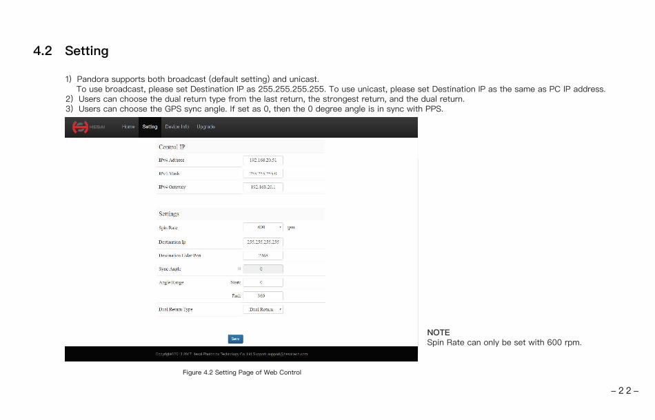
4.2 Setting
1) Pandora supports both broadcast (default setting) and unicast. To use broadcast, please set Destination IP as 255.255.255.255. To use unicast, please set Destination IP as the same as PC IP address. 2) Users can choose the dual return type from the last return, the strongest return, and the dual return.3) Users can choose the GPS sync angle. If set as 0, then the 0 degree angle is in sync with PPS.
NOTESpin Rate can only be set with 600 rpm.
Figure 4.2 Setting Page of Web Control
- 2 2 -
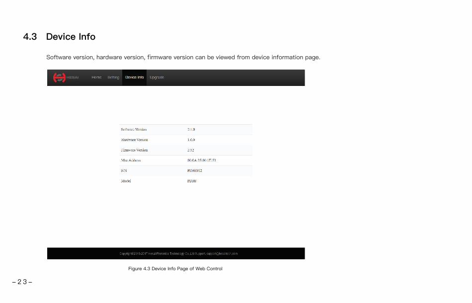
4.3 Device Info
Software version, hardware version, firmware version can be viewed from device information page.
Figure 4.3 Device Info Page of Web Control
- 2 3 -
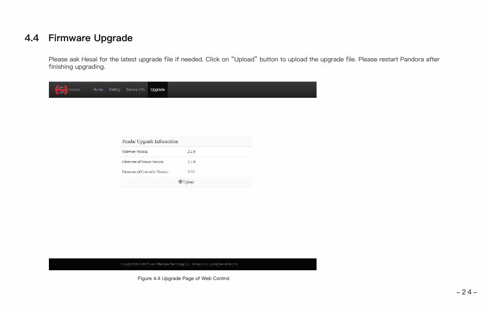
4.4 Firmware Upgrade
Please ask Hesai for the latest upgrade file if needed. Click on “Upload” button to upload the upgrade file. Please restart Pandora after finishing upgrading.
Figure 4.4 Upgrade Page of Web Control
- 2 4 -

LiDAR Channel Distribution
Appendix I
Channel Number of Laser
Channel number in UDP Data Packet
01 (Top Line)
02
03
04
05
06
07
08
09
10
11
12 (Horizontal Line)
13
14
Horizontal Angle Offset (Azimuth)
The horizontal angle of each line is the sum of current reference angle of the rotor and the angle
below. Define clockwise as positive.
0.00
0.00
0.00
0.00
-2.50
-2.50
2.50
-5.00
-2.50
2.50
-5.00
-2.50
2.50
-5.00
Vertical Angle (Elevation)
The vertical angle of each line is constant, and 0° represents horizontal direction. Define upward as
positive.
7.00
6.00
5.00
4.00
3.00
2.00
1.67
1.33
1.00
0.67
0.33
0.00
-0.33
-0.67
0.00
2.50
-5.00
-1.00
-1.33
-1.67
15
16
17
- 2 5 -

Channel Number of Laser
18
19
20
21
22
23
24
25
26
27
28
Horizontal Angle Offset (Azimuth)
0.00
5.00
-2.50
0.00
5.00
-2.50
0.00
5.00
-2.50
2.50
5.00
Vertical Angle (Elevation)
-2.00
-2.33
-2.67
-3.00
-3.33
-3.67
-4.00
-4.33
-4.67
-5.00
-5.33
29 -2.50 -5.67
30 2.50 -6.00
31 2.50 -7.00
32
33
2.50
0.00
-8.00
-9.00
34
35
36
37
38
39
40 (Bottom Line)
Table I.1 LiDAR Channel Distrbution
0.00
0.00
0.00
-2.50
-2.50
-2.50
-2.50
-10.00
-11.00
-12.00
-13.00
-14.00
-15.00
-16.00
- 2 6 -

Appendix II
Point Cloud Data Packet Absolute Time and Laser Firing Time Calculations
Pandora transmits a GPS Data Packet and a Point Cloud Data Packet chronologically with μs timestamps from the same data source. The μs timestamp in the Point Cloud Data Packet (GPS Timestamp) is used to calculate the packing time of this data packet.
There are two methods to calculate the absolute packing time of Point Cloud Data:
1)
2)
Retrieve the μs timestamp and the time information (UTC, decimal number) from the Point Cloud Data Packet. The absolute time of Point Cloud Data Packet can be calculated by combining two parts: a) the 4 bytes μs timestamp; b) the 6 bytes UTC time information (decimal number) in Point Cloud Data Packet.
First retrieve timestamp from the Point Cloud Data Packet, then retrieve time information (UTC) from the most recent GPS Data Packet. The absolute time of Point Cloud Data Packet can be calculated by combining two parts: a) the 4 bytes μs timestamp; b) the UTC time information (decimal number) in most recent GPS Data Packet.
Absolute Time Calculation of Point Cloud Data Packet1
Pandora transmits two types of UDP Data Packet, including the Point Cloud UDP Data Packet and the GPS UDP Data Packet, hereafter referred to as Point Cloud Data Packet and GPS Data Packet.
- 2 7 -

NOTE1)
2)
3)
Because Pandora GPS Data Packet is triggered by PPS rising edge, the corresponding GPRMC information (real absolute time) from GPS module after PPS rising edge is not available at that time.
The UTC time in Pandora GPS Data Packet and following Point Cloud Data Packet are same and derived from previous GPRMC information. Although previous GPRMC is 1 full second older than the absolute time of the triggering PPS rising edge, Pandora has an adjustment mechanism so that the UTC time is exactly the absolute time of triggering PPS rising edge.
Since every GPS Data Packet matches an internal 1Hz signal, the GPS Data Packet will be exported continuously in every second with or without GPRMC information. If GPRMC is available, UTC time in data packets are updated according to GPRMC and avoid drift of internal 1Hz signal; if GPRMC is not available, UTC time in data packets are updated according to internal 1Hz signal and keep the mechanism.
Ranging Data 1240 bytes (10 blocks)
Table II.1 Point Could Data UDP Data-Ranging Data
Block 1 Block 2 Block 3 Block 10
0xFFEE 0xFFEE 0xFFEE 0xFFEE
Azimuth Angle 1 Azimuth Angle 2 Azimuth Angle 3 Azimuth Angle 10
Channel 1 Unit 1 Channel 1 Unit 2 Channel 1 Unit 3 Channel 1 Unit 10
Channel 2 Unit 1 Channel 2 Unit 2 Channel 2 Unit 3 Channel 2 Unit 10
Channel 40 Unit 1 Channel 40 Unit 2 Channel 40 Unit 3 Channel 40 Unit 10
······ ······ ······ ······
······
······
············
······
······
······
The laser firing time of every laser channel can be calculated by using the absolute time in Point Cloud Data Packet.Assuming the Point Cloud Data Packet's absolute time is t0.
Laser Firing Time Calculation2
- 2 8 -

01) End time of Block10: (t0-28.58) μs;
02) End time of BlockN: (t0-28.58-55.56*(10-N)) μs;
03) End time of Block3: (t0-28.58-55.56*7) μs;
04) End time of Block2: (t0-28.58-55.56*8) μs;
05) End time of Block1: (t0-28.58-55.56*9) μs;
There are 10 Blocks in every Point Cloud UDP Data Packet.
In the single return mode, each block consists 40 laser channels ranging data. The end time of the Block means all the 40 channels
laser finished the firing.
The calculation of each Block's end time is as follows:
Single Return Mode
1) End time of Block10: (t0-28.58) μs;
2) End time of Block9: (t0-28.58) μs;
3) End time of Block8: (t0-28.58-55.56*1) μs;
4) End time of Block7: (t0-28.58-55.56*1) μs;
5) End time of Block6: (t0-28.58-55.56*2) μs;
6) End time of Block5: (t0-28.58-55.56*2) μs;
7) End time of Block4: (t0-28.58-55.56*3) μs;
8) End time of Block3: (t0-28.58-55.56*3) μs;
9) End time of Block2: (t0-28.58-55.56*4) μs;
10) End time of Block1: (t0-28.58-55.56*4) μs;
There are 10 Blocks in every Point Cloud UDP Data Packet.
In the dual return mode, Block (1, 2) are corresponding to dual return ranging data for the same 40 channels laser firing, so they have
the same firing time for each laser and the same end time for the Block. Similarly, Block (3, 4) and so on have same firing and end time.
The calculation of each Block's end time is as follows:
Dual Return Mode
- 2 9 -
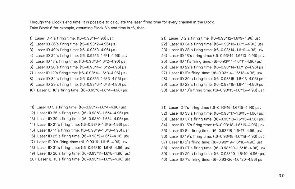
1)Laser ID 4’s firing time: (t6-0.93*1-4.96) μs;
2)Laser ID 36’s firing time: (t6-0.93*2-4.96) μs;
3)Laser ID 40’s firing time: (t6-0.93*3-4.96) μs;
4)Laser ID 24’s firing time: (t6-0.93*3-1.6*1-4.96) μs;
5)Laser ID 17’s firing time: (t6-0.93*3-1.6*2-4.96) μs;
6)Laser ID 28’s firing time: (t6-0.93*4-1.6*2-4.96) μs;
7)Laser ID 12’s firing time: (t6-0.93*4-1.6*3-4.96) μs;
8)Laser ID 32’s firing time: (t6-0.93*5-1.6*3-4.96) μs;
9)Laser ID 29’s firing time: (t6-0.93*6-1.6*3-4.96) μs;
10)Laser ID 16’s firing time: (t6-0.93*6-1.6*4-4.96) μs;
11)Laser ID 3’s firing time: (t6-0.93*7-1.6*4-4.96) μs;
12)Laser ID 35’s firing time: (t6-0.93*8-1.6*4-4.96) μs;
13)Laser ID 39’s firing time: (t6-0.93*9-1.6*4-4.96) μs;
14)Laser ID 21’s firing time: (t6-0.93*9-1.6*5-4.96) μs;
15)Laser ID 14’s firing time: (t6-0.93*9-1.6*6-4.96) μs;
16)Laser ID 25’s firing time: (t6-0.93*9-1.6*7-4.96) μs;
17)Laser ID 9’s firing time: (t6-0.93*9-1.6*8-4.96) μs;
18)Laser ID 31’s firing time: (t6-0.93*10-1.6*8-4.96) μs;
19)Laser ID 26’s firing time: (t6-0.93*11-1.6*8-4.96) μs;
20)Laser ID 13’s firing time: (t6-0.93*11-1.6*9-4.96) μs;
Through the Block's end time, it is possible to calculate the laser firing time for every channel in the Block.
Take Block 6 for example, assuming Block 6's end time is t6, then:
21)Laser ID 2’s firing time: (t6-0.93*12-1.6*9-4.96) μs;
22)Laser ID 34’s firing time: (t6-0.93*13-1.6*9-4.96) μs;
23)Laser ID 38’s firing time: (t6-0.93*14-1.6*9-4.96) μs;
24)Laser ID 18’s firing time: (t6-0.93*14-1.6*10-4.96) μs;
25)Laser ID 11’s firing time: (t6-0.93*14-1.6*11-4.96) μs;
26)Laser ID 22’s firing time: (t6-0.93*14-1.6*12-4.96) μs;
27)Laser ID 6’s firing time: (t6-0.93*14-1.6*13-4.96) μs;
28)Laser ID 30’s firing time: (t6-0.93*15-1.6*13-4.96) μs;
29)Laser ID 23’s firing time: (t6-0.93*15-1.6*14-4.96) μs;
30)Laser ID 10’s firing time: (t6-0.93*15-1.6*15-4.96) μs;
31)Laser ID 1’s firing time: (t6-0.93*16-1.6*15-4.96) μs;
32)Laser ID 33’s firing time: (t6-0.93*17-1.6*15-4.96) μs;
33)Laser ID 37’s firing time: (t6-0.93*18-1.6*15-4.96) μs;
34)Laser ID 15’s firing time: (t6-0.93*18-1.6*16-4.96) μs;
35)Laser ID 8’s firing time: (t6-0.93*18-1.6*17-4.96) μs;
36)Laser ID 19’s firing time: (t6-0.93*18-1.6*18-4.96) μs;
37)Laser ID 5’s firing time: (t6-0.93*19-1.6*18-4.96) μs;
38)Laser ID 27’s firing time: (t6-0.93*20-1.6*18-4.96) μs;
39)Laser ID 20’s firing time: (t6-0.93*20-1.6*19-4.96) μs;
40)Laser ID 7’s firing time: (t6-0.93*20-1.6*20-4.96) μs;
- 3 0 -

PandarViewPandarView is a software that is used to play and record the point cloud data. Installations are available on platforms: Windows 7x64/ Windows 8x64/ Windows 10x64/ Ubuntu-16.04The installation package can be downloaded from Hesai official webpage under “development data”.
Appendix III
Please install the PandarView and set the computer static IP address to 192.168. 20.100 before running.
Table III.1 PandarView Installation Steps
1 PandarView Installation
Ubuntu-16.04:The IP address can be configured on the terminal by using the ifconfig command:~$ sudo ifconfig enp0s20f0u2 192.168.20.100Replace enp0s20f0u2 with the local network port name.
Windows: 1) Open the Network Sharing Center, click on “Ethernet”. 2) In the “Ethernet Status” interface, click on “Properties” to proceed to the next interface.3) Double-click on “Internet Protocol Version 4 (TCP/IPv4)”4) Configure the IP address to 192.168.20.100 and subnet mask to 255.255.255.0, then click “OK” to finish configuration.
IP配置
System Installation FilesSystem
Windows
Ubuntu-16.04
1. Double-click on python-2.7.13.msi2. Double-click on PandarView-v1.5.2.msi (install with default settings)
Pandar.exe shortcuts will show on the desktop after installation:
Installation Steps Finish Installation
1. Enter the following command at the terminal: sudo apt-get install qt4-default libboost-all-dev.2. Unzip the installation file3. Run PandarView_Installer.bin
- 3 1 -
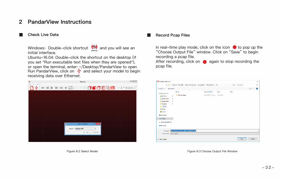
Run PandarView, click on and select your model to begin receiving data over Ethernet.
2 PandarView Instructions
Windows:Double-click shortcut and you will see an initial interface.Ubuntu-16.04: Double-click the shortcut on the desktop (if you set "Run executable text files when they are opened"), or open the terminal, enter: ~/Desktop/PandarView to open
Figure III.2 Select Model
Check Live Data
In real-time play mode, click on the icon to pop up the “Choose Output File” window. Click on “Save” to begin recording a pcap file.After recording, click on again to stop recording the pcap file.
Figure III.3 Choose Output File Window
Record Pcap Files
- 3 2 -

Play Pcap Files
Click on the icon to open the “Choose Open File” window.
Select the pcap file and click on the icon to open.
Figure III.4 Choose Open File Window Figure III.5 Ready to Play the Pcap File
Click on to begin playing the pcap file and visualizing point
cloud data.
Import Correction File
Figure III.6 File Menu
Each Pandora comes with a correction file (CSV) in the provided USB disk.
In the play mode, click on “File” in the upper left corner. Choose “Import Correction File” in the drop-down
menu, select and open the correction file to display the calibrated point cloud.
- 3 3 -

Play Button
Jump to the beginning of the file.
1. While paused, click to view point cloud data from the previous frame.2. While playing, rewind (click again for different speeds, such as 2x, 3x, 1/2x, 1/4x, 1x speeds).
1. After the point cloud file has finished loading, click on to play.2. While playing, click on to pause.
1.While paused, click to view point cloud data in next frame.2.While playing, forward (click again for different speeds, such as 2x, 3x, 1/2x, 1/4x, 1x speeds).
Jump to the end of the file.
While playing pcap file, the recording button will be gray and unclickable.
While playing pcap file, click on this button to loop playback, else playback will stop at the end of the file.
Progress bar: drag to control playback speed, or enter frame number to jump to the desired frame.
Table III.2 Play Buttons Description
Button Description
- 3 4 -

Distance Reference Circle
In Orthogonal Projection view, click on , thereafter while holding “Control” on the keyboard, select a point and hold down the left mouse button to create a spatial distance reference, in units of meters. Click on again to cancel the distance reference.
Figure III.9 Distance Reference Circle
3D Projection Mode
PandarView enables switching between two types of 3D projection methods (Orthogonal Projection and Perspective Projection) through the drop-down menu.
Click on to show/hide 12 gray distance reference circles. The corresponding actual distances are as shown above. The lower left axis shows the current viewing position. Click “Tools” to open “Grid Properties”, where you can change the color and width of the circles.
Mouse Shortcuts
Hold left button Hold scrollScroll
01. Slide scroll wheel to magnify/minimize02. Drag while holding left button to adjust the view angle03. Drag while holding scroll wheel to pan
Up
Down
View Direction Selection
Front POV Top POVRight POV
Click on the following buttons to view the point cloud from different directions.
Figure III.7 View Direction Selection
Figure III.8 View Direction Selection
3 PandarView Features
- 3 5 -

Point Cloud Data Selection
Users can click on to display or hide point cloud data from any selected laser channels. Clicking on this icon will pop up the following interface. Click on again to close the interface.
Clicking on the left-side checkboxes to show/hide any given channel’s display. Checking the “Enable/Disable all” option in the bottom left corner to show/hide all channels at once.
The main data shown about the points are their id, x, y and z values, angle, distance, reflectivity, corresponding channel id and timestamp (μs) information.
Figure III.10 Channel Display Figure III.11 Detailed Data of Selected Point Cloud
Clicking on to select visible points. Users can hold down the left button to box a certain area for selection. The selected points will be highlighted. Click on to view detailed data of the selected point clouds. Click on again, select an area outside of the point cloud to deselect.
- 3 6 -

Click to compensate the azimuth error caused by the delay of laser activation.
Click on to open “Color Editor”,where users can customize colors. click the button again to close the color editor.
Color Schemes
By Clicking on , users can see the current color scheme in the lower right corner.The drop-down list is used to choose different color schemes. The default color scheme of point cloud is drawing according to the intensity. Users can choose azimuth, distance, laser_id, or timestamp as the color scheme as well.
Figure III.12 Current Color Scheme Figure III.13 Color Editor
- 3 7 -
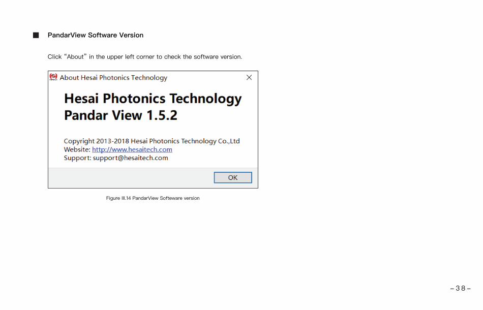
Click “About” in the upper left corner to check the software version.
Figure III.14 PandarView Softeware version
PandarView Software Version
- 3 8 -
Appendix IV
Support and Contact
If you have any problems, and cannot find the solution in this manual please contact us:
E-mail: [email protected]
Website: www.hesaitech.com
GitHub: https://github.com/HesaiTechnology
NOTE If you have any questions about the open source we provide on GitHub, please leave your questions under corresponding projects.
Technical Support
If any defect due to faulty software and/or hardware occurs within the warranty period, Hesai Photonics Technology Co., Ltd will provide free
maintenance service. Some operations will violate the warranty, including but not limited to the following:
1) The purchase documents have been altered in any way, made illegible or lost.
2) The defect is caused by abuse or misuse of the product or by environmental conditions that are not in conformance with the
recommended operating condition of the product.
3) Repairs or product modifications, alterations and disassemble have been carried out by unauthorized personals.
4) The unit was stolen, lost or discarded.
5) The damage to the unit is caused by the event of force majeure, including but not limited: abnormal voltage, water or fire, natural disaster
or transport accident.
Warranty and Maintenance
- 3 9 -

All texts, graphics, and pictures in this manual are subject to the copyright of Shanghai Hesai Photonics Technology Co., Ltd and are
potentially protected by copyright through third parties. No part of the manual may be reproduced, processed, duplicated or published in
any form by photocopying, reprinting or other process, without a written agreement. Despite careful examination, we cannot assume any
liability for the accuracy and legality of the contents published in the manual.
The Customer is not permitted, except as expressly permitted by this Agreement and save to the extent and in the circumstances expressly
required to be permitted by law, to rent, lease, sub-license, loan, copy, modify, adapt, merge, translate, reverse engineer, decompile,
disassemble or create derivative works based on the whole or any part of the Software or its associated documentation or use, reproduce
or deal in the Software or any part of it in any way.
Legal Notice
The contents of user's manual are provided “as is” and without warranties of any kind, either express or implied. To the fullest extent
permissible pursuant to applicable law, Hesai Photonics Technology Co., Ltd disclaims all warranties, express or implied, including but not
limited to, warranties of merchantability or fitness for a particular purpose.
In no event shall Hesai Photonics Technology Co., Ltd be liable for any direct, indirect, special, punitive, incidental, exemplary or
consequential, damages, or any damages.
To the extent permissible pursuant to applicable law, the maximum liability of Hesai Photonics Technology Co., Ltd to you shall not exceed
the amount paid by you for the products or services you have ordered.
Limitation of Liability
- 4 0 -

Hesai Photonics Technology Co., Ltd
Phone: 021-80394947-876
Technical Support: 021-80394947-915
Website: www.hesaitech.com
Business Email: [email protected]
Service Email: [email protected]
Address: Building L2, Hongqiao World Centre, Shanghai
HESAI Wechat