oss-306_2012-04
58
OFFSHORE SERVICE SPECIFICATION DET NORSKE VERITAS AS The electronic pdf version of this document found through http://www.dnv.com is the officially binding version DNV-OSS-306 Verification of Subsea Facilities JUNE 2004 This document has been amended since the main revision (June 2004), most recently in April 2012. See “Changes” on page 3.
-
Upload
shavin-fernando -
Category
Documents
-
view
215 -
download
0
Transcript of oss-306_2012-04

8/10/2019 oss-306_2012-04
http://slidepdf.com/reader/full/oss-3062012-04 1/58
OFFSHORE SERVICE SPECIFICATION
DET NORSKE VERITAS AS
The electronic pdf version of this document found through http://www.dnv.com is the officially binding version
DNV-OSS-306
Verification ofSubsea Facilities
JUNE 2004
This document has been amended since the main revision (June 2004), most recently in April 2012.See “Changes” on page 3.
8/10/2019 oss-306_2012-04
http://slidepdf.com/reader/full/oss-3062012-04 2/58
© Det Norske Veritas AS June 2004
Any comments may be sent by e-mail to [email protected] subscription orders or information about subscription terms, please use [email protected]
Computer Typesetting (Adobe Frame Maker) by Det Norske Veritas
This service document has been prepared based on available knowledge, technology and/or information at the time of issuance of this document, and is believed to reflect the best of contemporary technology. The use of this document by others than DNV is at the user's sole risk. DNV does not accept any liability or responsibility for loss or damages resulting fromany use of this document.
FOREWORD
DET NORSKE VERITAS (DNV) is an autonomous and independent foundation with the objectives of safeguarding life, property and the environment, at sea and onshore. DNV undertakes classification, certification, and other verification andconsultancy services relating to quality of ships, offshore units and installations, and onshore industries worldwide, andcarries out research in relation to these functions.
DNV service documents consist of amongst other the following types of documents:
— Service Specifications. Procedual requirements.
— Standards. Technical requirements. — Recommended Practices. Guidance.
The Standards and Recommended Practices are offered within the following areas:
A) Qualification, Quality and Safety Methodology
B) Materials Technology
C) Structures
D) Systems
E) Special Facilities
F) Pipelines and Risers
G) Asset Operation
H) Marine Operations
J) Cleaner EnergyO) Subsea Systems

8/10/2019 oss-306_2012-04
http://slidepdf.com/reader/full/oss-3062012-04 3/58DET NORSKE VERITAS AS
Amended April 2012 Offshore Service Specification DNV-OSS-306, June 2004
see note on front cover Changes – Page 3
CHANGES
INTRODUCTION
This Service Specification was approved by the Director of Technology in June 2004.
The suit of inter-related DNV-OSS documents consist of a general description of the verification systematics(DNV-OSS-300) and object specific documents - this document (DNV-OSS-306) offers the reader the
application of the common framework and overview of processes in risk verification, to subsea facilities. — It introduces a levelled description of verification involvement during all phases of an asset's life. — The document facilitates a categorisation into risk levels High, Medium and Low, assisting in an evaluation
of the risk level. — The document assists in planning the verification through the making of a Verification Plan, and describes
the DNV documentation of the process throughout.
The document provides an international standard allowing transparent and predictable verification scope, aswell as defining terminology for verification involvement.
Amendments April 2012
— The restricted use legal clause has been deleted from the front page.
Amendments October 2011
— A restricted use legal clause has been added on the front page.
8/10/2019 oss-306_2012-04
http://slidepdf.com/reader/full/oss-3062012-04 4/58DET NORSKE VERITAS AS
Offshore Service Specification DNV-OSS-306, June 2004 Amended April 2012
Page 4 – Contents see note on front cover
CONTENTS
Sec. 1 General ............................................................................................................................................... 6
A. General...........................................................................................................................................................................6A 100 Introduction........................................................................................................................................................... 6A 200 Objectives .............................................................................................................................................................6A 300 Scope of application for verification.....................................................................................................................6A 400 Structure of this document ................................................................................................................................... 6
B. Risk Based Verification ................................................................................................................................................7B 100 Elements of the service ......................................................................................................................................... 7
C. Defining a Verification Plan......................................................................................................................................... 7C 100 Risk based verification planning...........................................................................................................................7
D. DNV Subsea Facility Statements of Compliance ....................................................................................................... 8D 100 General on verification ......................................................................................................................................... 8D 200 Statement of compliance.......................................................................................................................................8D 300 General on certification......................................................................................................................................... 8
E. Definitions / Abbreviations...........................................................................................................................................8E 100 General ..................................................................................................................................................................8
E 200 Abbreviations........................................................................................................................................................8E 300 Verbal forms .........................................................................................................................................................8E 400 Definitions ............................................................................................................................................................8
F. References ....................................................................................................................................................................10F 100 General ................................................................................................................................................................ 10
Sec. 2 Service Overview .............................................................................................................................. 11
A. General.........................................................................................................................................................................11A 100 Objectives ...........................................................................................................................................................11
B. Service Process ............................................................................................................................................................11B 100 General principles ............................................................................................................................................... 11B 200 Simplified verification planning .........................................................................................................................11B 300 Selection of level of verification.........................................................................................................................12
B 400 Codes, standards and reference documents ........................................................................................................ 12C. Project Initiation .........................................................................................................................................................12C 100 Verification during conceptual design ................................................................................................................12
D. Project Realization ...................................................................................................................................................... 12D 100 General ................................................................................................................................................................ 12D 200 Verification of overall project management .......................................................................................................12D 300 Verification During Design................................................................................................................................. 13D 400 Verification During Construction .......................................................................................................................14
E. Project Operation........................................................................................................................................................ 16E 100 Verification during operation .............................................................................................................................16
F. Verification Documents ..............................................................................................................................................17F 100 General ................................................................................................................................................................ 17
App. A Selection of Verification Level ........................................................................................................ 18
A. General.........................................................................................................................................................................18A 100 General principles ............................................................................................................................................... 18
B. Trigger Questions........................................................................................................................................................ 18B 100 Overall project objective and goals..................................................................................................................... 18B 200 Assessment of risk .............................................................................................................................................. 18B 300 Technical innovation........................................................................................................................................... 19B 400 Contractors’ experience ......................................................................................................................................19B 500 Quality management systems .............................................................................................................................19
App. B Detailed Example Scope of Work Tables for Verification ........................................................... 20
A. General.........................................................................................................................................................................20
A 100 General introduction ..........................................................................................................................................20B. Description of Terms Used in the Verification Lists................................................................................................20B 100 General ................................................................................................................................................................ 20B 200 Audit ...................................................................................................................................................................20B 300 Surveillance ........................................................................................................................................................21

8/10/2019 oss-306_2012-04
http://slidepdf.com/reader/full/oss-3062012-04 5/58DET NORSKE VERITAS AS
Amended April 2012 Offshore Service Specification DNV-OSS-306, June 2004
see note on front cover Contents – Page 5
B 400 Hold point witnessing .........................................................................................................................................21B 500 Review ................................................................................................................................................................ 21
C. Overall Project Management.....................................................................................................................................21C 100 General ................................................................................................................................................................ 21
D. Design ...........................................................................................................................................................................22D 100 General ................................................................................................................................................................ 22D 200 Design Verification............................................................................................................................................. 22
D 300 Low level Design Verification............................................................................................................................ 22D 400 Medium level Design Verification......................................................................................................................22D 500 High level Design Verification ...........................................................................................................................22
E. Construction ................................................................................................................................................................36E 100 General ................................................................................................................................................................ 36E 200 Construction Verification ................................................................................................................................... 36E 300 Low Level Construction Verification................................................................................................................. 36E 400 Medium Level Construction Verification...........................................................................................................36E 500 High Level Construction Verification ................................................................................................................36E 600 Verification of Work in Progress........................................................................................................................37E 700 DNV Final Report...............................................................................................................................................37
App. C Examples of Verification Documents ............................................................................................. 50
A. Verification documents...............................................................................................................................................50A 100 Validity of verification documents .....................................................................................................................50A 200 Statement of compliance ....................................................................................................................................50A 300 Verification reports ............................................................................................................................................. 50A 400 Verification comments .......................................................................................................................................50A 500 Audit report......................................................................................................................................................... 50A 600 Visit reports.........................................................................................................................................................51
B. Use of Quality Management Systems .......................................................................................................................51B 100 General ................................................................................................................................................................ 51B 200 Quality plans.......................................................................................................................................................51B 300 Inspection and test plans .....................................................................................................................................52B 400 Review of quality management programme.......................................................................................................52
C. Document forms ..........................................................................................................................................................53C 100 Introduction......................................................................................................................................................... 53
C 200 Statement of compliance.....................................................................................................................................54C 300 Verification comments sheet............................................................................................................................... 55C 400 Audit report......................................................................................................................................................... 56C 500 Visit report .......................................................................................................................................................... 58
8/10/2019 oss-306_2012-04
http://slidepdf.com/reader/full/oss-3062012-04 6/58DET NORSKE VERITAS AS
Offshore Service Specification DNV-OSS-306, June 2004 Amended April 2012
Page 6 – Sec.1 see note on front cover
SECTION 1GENERAL
A. General
A 100 Introduction101 This DNV Offshore Service Specification (DNV-OSS-306) gives criteria for and guidance onverification of the integrity and function of parts or phases of subsea facilities.
102 This specification falls under the top level document DNV-OSS-300 Risk Based Verification.
103 The descriptions in this specification directly support a simplified verification planning as described inSec.2 F of DNV-OSS-300. When using the advanced or combined planning, the descriptions will give goodreferences and starting points.
Guidance note:
The latest revision of all DNV documents may be found in the publications list in the DNV web site www.dnv.com.
---e-n-d---of---G-u-i-d-a-n-c-e---n-o-t-e---
A 200 Objectives
201 The objectives of this specification are to describe the following for a subsea facility:
— preparation of a Verification Plan using DNV’s risk differentiated levels of verification activities anddetailed example scope of work tables
— DNV’s implementation and reporting of the Verification Plan
A 300 Scope of application for verification
301 This specification may be adopted for the verification of parts of subsea facilities or selected project phases.
302 Subsea facilities typically comprise the following systems:
— Downhole system — Subsea wellhead and tree system (including: choke, tubing hanger and connection systems)
— Manifold, foundations and template — Flowlines and risers (including dynamic umbilical risers) — Subsea control umbilicals — Subsea production control system — Subsea processing system — Well intervention/completion/workover system — ROT intervention system
which are applied in various configurations and tailored to each particular project’s specific requirements.
303 This specification describes the principles of a levelled verification involvement. These principles may be applied both for planning of any need or obligations for independent external verification (third party) aswell as internal company verification (second party).
A 400 Structure of this document
— Section 1 explains the relationship between this document and DNV’s overall risk based verificationsystematics.
— Section 2 describes the activities for each project and the project phases for a subsea system. — Appendix A poses trigger questions to assist in the selection of verification level example — Appendix B gives detailed scope of work tables for the different phases and levels of involvement. These
tables are the basis for the development of project specific scope of work tables. — Appendix C gives example verification documents and describes the documents issued during and as a
result of the verification process. The use of quality management systems is addressed here also.
8/10/2019 oss-306_2012-04
http://slidepdf.com/reader/full/oss-3062012-04 7/58DET NORSKE VERITAS AS
Amended April 2012 Offshore Service Specification DNV-OSS-306, June 2004
see note on front cover Sec.1 – Page 7
B. Risk Based Verification
B 100 Elements of the service
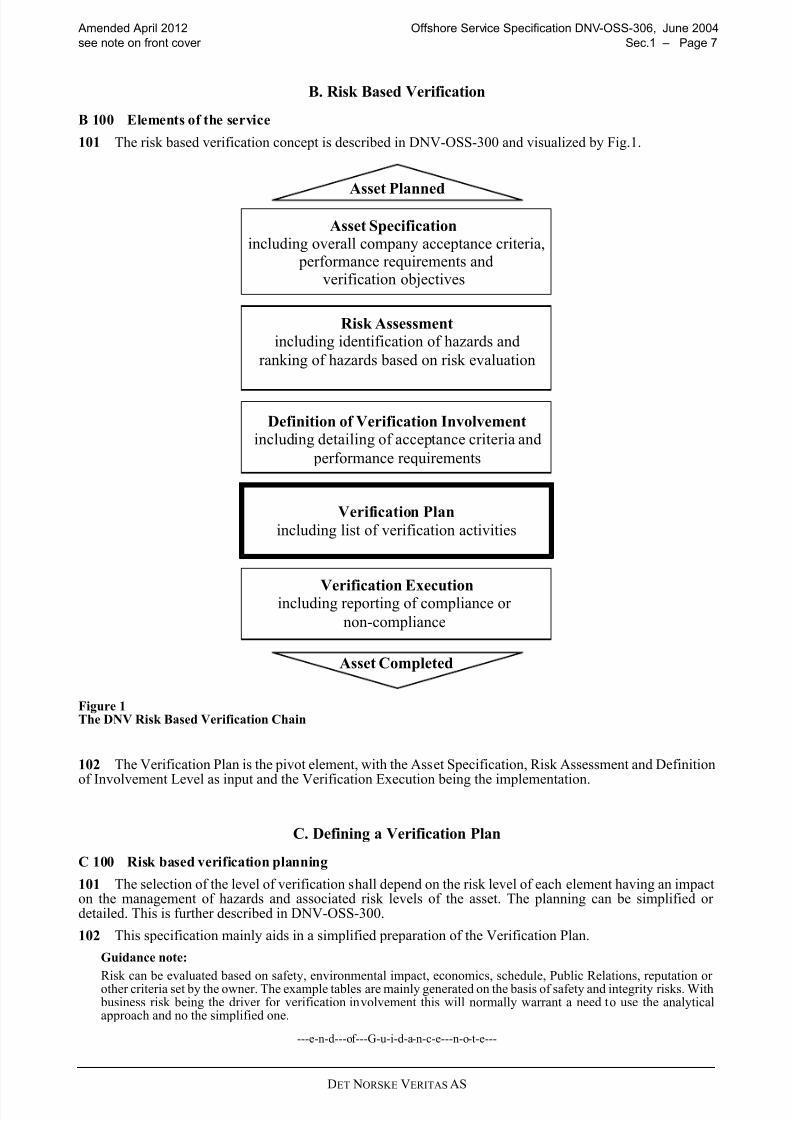
101 The risk based verification concept is described in DNV-OSS-300 and visualized by Fig.1.
Figure 1The DNV Risk Based Verification Chain
102 The Verification Plan is the pivot element, with the Asset Specification, Risk Assessment and Definition
of Involvement Level as input and the Verification Execution being the implementation.
C. Defining a Verification Plan
C 100 Risk based verification planning
101 The selection of the level of verification shall depend on the risk level of each element having an impacton the management of hazards and associated risk levels of the asset. The planning can be simplified or detailed. This is further described in DNV-OSS-300.
102 This specification mainly aids in a simplified preparation of the Verification Plan.
Guidance note:
Risk can be evaluated based on safety, environmental impact, economics, schedule, Public Relations, reputation or other criteria set by the owner. The example tables are mainly generated on the basis of safety and integrity risks. With business risk being the driver for verification involvement this will normally warrant a need to use the analyticalapproach and no the simplified one.
---e-n-d---of---G-u-i-d-a-n-c-e---n-o-t-e---
Risk Assessmentincluding identification of hazards and
ranking of hazards based on risk evaluation
Verification Executionincluding reporting of compliance or
non-compliance
Asset Planned
Asset Specification
performance requirements andverification objectives
including overall company acceptance criteria,
Definition of Verification Involvementincluding detailing of acceptance criteria and
performance requirements
Verification Plan
including list of verification activities
Asset Completed
8/10/2019 oss-306_2012-04
http://slidepdf.com/reader/full/oss-3062012-04 8/58DET NORSKE VERITAS AS
Offshore Service Specification DNV-OSS-306, June 2004 Amended April 2012
Page 8 – Sec.1 see note on front cover
D. DNV Subsea Facility Statements of Compliance
D 100 General on verification
101 Verification describes the individual activities undertaken by DNV at the various stages of design,construction and operation of the subsea facility. The scope of the verification plan is ultimately determined
by the owner.
D 200 Statement of compliance201 A statement of Compliance may be issued by DNV to confirm compliance according to the scope of work.
D 300 General on certification
301 Certification describes the totality of verification activities leading up to the issue of a Certification of Conformity. The scope of work and verification plan, called a Certification Plan, is set by DNV. All design andconstruction aspects, related to subsea facility safety and integrity, must be covered by the Certification Plan.
302 This DNV-OSS does not define the scope of work necessary to achieve a DNV Certificate of Conformity.
E. Definitions / AbbreviationsE 100 General
101 Relevant definitions in ISO 13620 -1 also apply to this OSS.
E 200 Abbreviations
DCS Distributed Control SystemEDU Electrical Distribution UnitEPU Electrical Power UnitETU Electronic Test UnitHPU Hydraulic Power UnitHTP Hydraulic Test PanelMCC Motor Control Centre
MCS Master Control StationMQC Multi Quick Connector PT Pressure Transmitter SCM Subsea Control ModuleSCMMB SCM Mounting BaseSCR Subsea Control RoomSCU Subsea Control UnitSDU Subsea Distribution UnitSEM Subsea Electronic ModuleSPCU Subsea Power & Communication UnitTT Temperature Transmitter TUTU Topside Umbilical Termination UnitUPS Uninterrupted Power Supply
E 300 Verbal forms
301 “Shall”: Indicates requirements strictly to be followed in order to conform to this OSS and from whichno deviation is permitted.
302 “Should”: Indicates that among several possibilities, one is recommended as particularly suitable,without mentioning or excluding others, or that a certain course of action is preferred but not necessarilyrequired. Other possibilities may be applied subject to agreement.
303 “May”: Verbal form used to indicate a course of action permissible within the limits of the OSS.
E 400 Definitions
401 Client: DNV’s contractual partner. It may be the Purchaser, the Owner or the Contractor.
402 Construction phase: All phases during construction, including fabrication, installation, testing and
commissioning, up until the installation or system is safe and operable for intended use. In relation to subseafacilities, this include transportation, on-shore and on-barge assembly, installation, rectification, tie-in, pressure testing, commissioning and repair.
403 Design: All related engineering to design the subsea facilities including both structural as well asmaterial and corrosion.
8/10/2019 oss-306_2012-04
http://slidepdf.com/reader/full/oss-3062012-04 9/58DET NORSKE VERITAS AS
Amended April 2012 Offshore Service Specification DNV-OSS-306, June 2004
see note on front cover Sec.1 – Page 9
404 Design phase: An initial phase that takes a systematic approach to the production of specifications,drawings and other documents to ensure that the subsea facilities meets specified requirements (includingdesign reviews to ensure that design output is verified against design input requirements).
405 Fabrication: Activities related to the assembly of objects with a defined purpose. In relation to subseafacilities, fabrication typically refers to the process of assembly or transformation of e.g. plates, profiles and
pipes etc into production facilities and (installation /intervention) tools
406 Hazard: A deviation (departure from the design and operating intention) which could cause damage,injury or other form of loss (Chemical Industries Association HAZOP Guide).
407 HAZOP (HAZard and OPerability study): The application of a formal systematic critical examination tothe process and engineering intentions of new or existing facilities to assess the hazard potential of mal-operation or mal-function of individual items of equipment and their consequential effects on the facility as awhole (Chemical Industries Association HAZOP Guide).
408 Installation (activity): The operations related to installing the equipment or structure, e.g. marineoperations related to placing equipment on seabed, tie-in, piling of structure etc., including final testing and
preparation for operation.
409 Manufacture: Making of articles or materials, often in large volumes. In relation to subsea facilities, thistypically refers to activities for the production of various components under contracts from one or moreContractor or Supplier.
410 Operations (phase): The phase when the subsea facilities are being used for the purpose for which it wasdesigned.
411 Risk: The qualitative or quantitative likelihood of an accident or unplanned event occurring, consideredin conjunction with the potential consequences of such a failure. In quantitative terms, risk is the quantified
probability of a defined failure mode times its quantified consequence.
Guidance note:
Risk is not only related to physical failure modes, but also to operational errors, human errors and so on. For somerisks the functional failures or physical failure modes contributes less than 20% while more than 80% of the risk relates to other devices.
---e-n-d---of---G-u-i-d-a-n-c-e---n-o-t-e---
412 Risk Reduction Measures: Those measures taken to reduce the risks to the operation of subsea facilitiesand to the health and safety of personnel associated with it or in its vicinity by:
— Reduction in the probability of failure. — Mitigation of the consequences of failure.
Guidance note:
The usual order of preference of risk reduction measures is:
a) Inherent Safety
b) Prevention
c) Detection
d) Control
e) Mitigation
f) Emergency Response
---e-n-d---of---G-u-i-d-a-n-c-e---n-o-t-e---
413 Safety Objectives: The safety goals for the construction, operation and decommissioning of the subseafacilities including acceptance criteria for the level of risk acceptable to the Owner.
414 Statement of Compliance: A statement or report signed by a qualified party affirming that, at the time of assessment, the defined subsea facilities phase, or collection of activities, met the requirements stated by theOwner.
415 Verification: An examination to confirm that an activity, a product or a service is in accordance withspecified requirements.
Guidance note:
The examination shall be based on information, which can be proved true, based on facts obtained throughobservation, measurement, test or other means.
ISO 8402: 1994: Verification: Confirmation by examination and provision of objective evidence that specifiedrequirements have been fulfilled.
---e-n-d---of---G-u-i-d-a-n-c-e---n-o-t-e---

8/10/2019 oss-306_2012-04
http://slidepdf.com/reader/full/oss-3062012-04 10/58DET NORSKE VERITAS AS
Offshore Service Specification DNV-OSS-306, June 2004 Amended April 2012
Page 10 – Sec.1 see note on front cover
F. References
F 100 General
101 A Guide to Hazard and Operability Studies, 1979, Chemical Industries Association Limited, London
102 ISO 8402 Quality – Vocabulary, 1994, International Organization for Standardization, Geneva
103 BS 4778 Quality Vocabulary, Part 2 Quality Concepts and Related Definitions, 1991, British Standards
Institute, London104 EN 45011 General Criteria for Certification Bodies Operating Product Certification, 1998, EuropeanCommittee for Standardization, Brussels
105 EN ISO 13628 Design and operation of subsea production systems - series.

8/10/2019 oss-306_2012-04
http://slidepdf.com/reader/full/oss-3062012-04 11/58DET NORSKE VERITAS AS
Amended April 2012 Offshore Service Specification DNV-OSS-306, June 2004
see note on front cover Sec.2 – Page 11
SECTION 2SERVICE OVERVIEW
A. General
A 100 Objectives101 The objectives of this section are to provide:
— an overview of life cycle verification activities relating to the system — details of DNV’s verification services for subsea facilities.
B. Service Process
B 100 General principles
101 The description of the process of DNV’s verification of subsea facilities is based on distinct project phases and the recognition of key milestones.
102 Verification performed by DNV normally progresses through one or more of these project phases andmay include all or selected aspects of the project.
103 The risk based verification process is described in relation to the normal project phases:
Project initiation:
— Conceptual design
Project realisation:
— Detail design — Construction — Manufacturing of subsea facilities — Manufacturing and fabrication of subsea facilities components and assemblies — Installation
— Project completion (pre-commissioning) — Commissioning — Issue of as-built/as-installed documentation, including Design Fabrication and Installation (DFI) resume
Project operation:
— Issue of Operation Manuals — Operations, maintenance and repair
Project abandonment
— Decommissioning — Removal
B 200 Simplified verification planning
201 The steps in the simplified verification planning are as follows:
— Use trigger questions to assess the overall risk level of the project (or manageable elements thereof). — Evaluate the risk against the relevant owner or project acceptance criteria (often this can be directly tied to
the owner core values or a sub-set of these) and decide whether the general verification involvement shall be Low, Medium or High.
— Use the example detailed scope of work tables in Appendix B to make a first draft of a Verification Plan — Generate the project specific Verification Plan by including a project specific engineering judgment or risk
analysis to adjust the table to suit the project. — Perform the verification execution according to the Verification Plan, making revision to the plan if and
when necessary. — Report the verification.
202 The trigger questions are included in Appendix A.
203 Generic scopes of work for verification at the three levels of verification; Low (L), Medium (M) and High(H), are given in the tables in this section.
204 Project specific detailed scope of work descriptions, based on the generic scopes of work tables andshowing all the activities to be verified, should be made. Examples of the level of detail are given in Appendix B.

8/10/2019 oss-306_2012-04
http://slidepdf.com/reader/full/oss-3062012-04 12/58DET NORSKE VERITAS AS
Offshore Service Specification DNV-OSS-306, June 2004 Amended April 2012
Page 12 – Sec.2 see note on front cover
205 It is the tables in this section 2 that give the principle difference between the levels of verificationinvolvement. The detailed example tables are to be treated as examples only. They shall not be used without a
project specific confirmation of their completeness.
206 The project specific scope of work definition, derived from the tables in Appendix B (or similar), shall be part of the final DNV verification report.
B 300 Selection of level of verification
301 The selection of the level of verification for the simplified verification planning is facilitated by thetrigger questions included in Appendix A.
B 400 Codes, standards and reference documents
401 The verification process described in this DNV-OSS is not tailored to a specific technical standard, codeor reference document.
402 It is recommended to use internationally recognised codes or standards. Where combinations of standards and external criteria are used the exact terms of reference and documents to be issued shall be agreedat the beginning of the project and formally defined in the contract.
403 It is recommended strongly not to mix standards due to the possible differences in safety philosophies.
Guidance note:
Most standards are a coherent collection of requirements for all the relevant aspects of a pipeline system. These
aspects, e.g. load and resistance, are normally among themselves adjusted to give an overall acceptable safety level.To pick requirements from different standards can then easily result in unpredictable (low) levels of safety, and non-uniform level of safety.
---e-n-d---of---G-u-i-d-a-n-c-e---n-o-t-e---
C. Project Initiation
C 100 Verification during conceptual design
101 Verification during the conceptual and/or feasibility studies of a project and in the early stages of a project can reduce the need for verification during the design and construction phases, and can reduce costsduring the long term operation, inspection and maintenance phases.
102 It is recommended to combine the mechanical design verification during project initiation phase withadditional review of:
— environmental aspects — project schedule — cost.
103 During this phase it can be beneficial to make an initial verification plan. Risk evaluations are carried outduring this phase and should be used to get an indication of the general verification level; Low, Medium or High.
D. Project Realization
D 100 General
101 All design and construction aspects, relevant to subsea facility, may be covered by the life cycleverification.
102 In this specification the split in the scope of work between design and construction is made between setsof requirements (specifications) developed during design and description of the steps necessary to satisfy thespecification (procedures) showing how construction will be implemented.
Guidance note:
The split between design and construction may vary, but it is useful spend some time on the definition to reduceinterface problems later.
---e-n-d---of---G-u-i-d-a-n-c-e---n-o-t-e---
D 200 Verification of overall project management
201 Verification of the overall project management is the examination of the means of controlling the entiresubsea development project, or the phase for which verification is undertaken.
202 This verification should confirm that the necessary controls are in place to ensure information flowacross the various interfaces. It is especially important where separate contractors have been employed for different phases of the project such as design and installation.

8/10/2019 oss-306_2012-04
http://slidepdf.com/reader/full/oss-3062012-04 13/58DET NORSKE VERITAS AS
Amended April 2012 Offshore Service Specification DNV-OSS-306, June 2004
see note on front cover Sec.2 – Page 13
203 Typically the documentation is expected to be in line with ISO 9000 requirements.
204 Definition of scope of work for verification of overall project management should follow Table 2-1.
205 The verification of the overall project management quality system and documentation is optional. Thereviews and audits should typically be performed if an extensive verification of a project is performed, whilemight be omitted for smaller sub-phase verifications.
D 300 Verification During Design
301 Design verification is the examination of the assumptions, methods and results of the design process andis performed at the specified level of verification to ensure that the specified requirements of the subsea facilitywill be achieved.
302 Design verification should consist of one, or some, of the following:
— review of the design process, — review of specifications for design (Asset specifications), — review of design reports and drawings, — performing of independent parallel calculations, — review of specifications for construction and operation, resulting from design.
303 The documents that shall be produced in the project should as a minimum satisfy the requirements of theselected code.
304 Definition of scope of work for verification of design should follow Table 2-2.
Table 2-1 Scope of work for verification of overall project management
Verification activity Level
L M H
Review of the project management process by — review of project quality management documentation. x x x
— audit of project quality management system x x
— review of sub-contractor control x x
— review of interface controls x x
— review of methods of information flow x x
Table 2-2 Scope of work for verification of design
Verification activity Level
L M H
Review of specifications for design by
— review of the design basis with emphasis on the design criteria x x x
Review of design reports and drawings by
— review of the main documentation to ensure that the main load conditions have been accountedfor in design, that the governing conditions are identified, and that the chosen design
philosophies are in accordance with specified codes and standards
x x x
— evaluation of the main methods used and spot checks of the input data and the calculation
results
x x
— detailed review of main design reports x
Performing independent parallel calculations by
— check of pressure containment or overallstructural integrity
x x x
— simplified independent analysis/calculation(s) performed by spot checks x x
— advanced independent analysis/calculation(s) performed by spot checks x
Review of specifications for construction andoperation by
— spot check of critical aspects x x x
— review of main specifications x x
— thorough review of main specifications x
Review of specific operational challenges (e.g. flow assurance
— general principles x x x
— review of main documents supported by simplified analyses x x

8/10/2019 oss-306_2012-04
http://slidepdf.com/reader/full/oss-3062012-04 14/58DET NORSKE VERITAS AS
Offshore Service Specification DNV-OSS-306, June 2004 Amended April 2012
Page 14 – Sec.2 see note on front cover
Guidance note:
Design verification activities may be split up between Basic Design and Detailed Design, or other sub-phases,depending on type of contract.
---e-n-d---of---G-u-i-d-a-n-c-e---n-o-t-e---
D 400 Verification During Construction
401 The construction phase comprises fabrication, manufacturing, sub-unit / unit integration testing,installation and commissioning. An important element is to ensure that the contractual design requirements areincorporated in the purchase documentation, and that correct materials, joining and corrosion control, have
been applied, and that pressure rating, capacity and function are meeting the requirements as per approvedspecifications and procedures. It is imperative that relevant preparations for this is started as early as possible,e.g. by the appointment of a vendor supply verification co-ordinator.
402 Verification during construction is carried out by means of full time attendance, audits, inspection or spotchecks of the work, as appropriate, in sufficient detail to ensure that the specified requirements of the subseafacility will be achieved.
403 Verification of these activities relates not only to the contractor’s work but also to the monitoring of thiswork carried out by others.
404 During construction verification should consist of one, or some, of the following:
— reviewing the construction process, — reviewing construction procedures, — reviewing qualification process, — surveillance during construction activities, — reviewing final documentation.
405 The documents that should be produced in the project and submitted for review prior to start up aretypically:
— Manufacturing Procedure Specification (MPS) — Manufacturing procedures, including test requirements and acceptance criteria, repairs, personnel
qualification records etc — Material specifications — Quality plans
— Welding Procedure Specifications (WPS) / Welding Procedure Qualification Record (WPQR) — NDT procedures — Manufacturing Procedure Qualification Test (MPQT) results; and — Manufacturer’s / fabricator’s quality system manual
406 Particularly for installation it is highly recommended to prepare a formal ‘ready for start of installation’document to be verified prior to commencement.
407 The “as-built” documentation to be submitted after manufacturing should include but not be limited to:
— Manufacturing procedures including test requirements and acceptance criteria, repairs, personnelqualification records etc
— Material certificates — Production test records (visual, NDT, test samples, dimensional, heat treatment etc.) — Hydrostatic test report — Commissioning report — Relevant statistics of chemical composition, mechanical properties and dimensions for the deliveries — Relevant logs
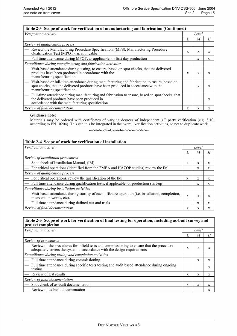
408 Definition of scope of work for verification of manufacturing and fabrication Table 2-3 and Table 2-4for installation and Table 2-5 for final testing and completion.
Table 2-3 Scope of work for verification of manufacturing and fabrication
Verification activity Level
L M H
Review of the manufacturing and fabrication process
— Review of manufacturing and fabrication management systems x x x
— Audit of the quality management system (x) x Review of manufacturing and fabrication procedures
— Review manufacturing, fabrication and inspection procedures for confirmation of compliancewith the manufacturing specification
x x x
— Review method statements x x
8/10/2019 oss-306_2012-04
http://slidepdf.com/reader/full/oss-3062012-04 15/58DET NORSKE VERITAS AS
Amended April 2012 Offshore Service Specification DNV-OSS-306, June 2004
see note on front cover Sec.2 – Page 15
Guidance note:
Materials may be ordered with certificates of varying degrees of independent 3rd party verification (e.g. 3.1Caccording to EN 10204). This can this be integrated in the overall verification activities, so not to duplicate work.
---e-n-d---of---G-u-i-d-a-n-c-e---n-o-t-e---
Review of qualification process
— Review the Manufacturing Procedure Specification, (MPS), Manufacturing ProcedureQualification Test (MPQT), as applicable
x x x
— Full time attendance during MPQT, as applicable, or first day production x xSurveillance during manufacturing and fabrication activities
— Visit-based attendance during testing, to ensure, based on spot checks, that the delivered products have been produced in accordance with themanufacturing specification
x x x
— Visit-based or full-time attendance during manufacturing and fabrication to ensure, based onspot checks, that the delivered products have been produced in accordance with themanufacturing specification
x x
— Full-time attendance during manufacturing and fabrication to ensure, based on spot checks, thatthe delivered products have been produced inaccordance with the manufacturing specification
x
Review of final documentation x x x
Table 2-4 Scope of work for verification of installation
Verification activity Level
L M H
Review of installation procedures
— Spot check of Installation Manual, (IM) x x x
— For critical operations (identified from the FMEA and HAZOP studies) review the IM x x
Review of qualification process
— For critical operations, review the qualification of the IM x x x
— Full time attendance during qualification tests, if applicable, or production start-up x x
Surveillance during installation activities
— Visit-based attendance during start up of each offshore operation (i.e. installation, completion,intervention works, etc).
x x x
— Full time attendance during defined test and trials x x
Review of final documentation x x x
Table 2-5 Scope of work for verification of final testing for operation, including as-built survey andproject completion
Verification activity Level
L M H Review of procedures
— Review of the procedures for infield tests and commissioning to ensure that the procedureadequately covers the system in accordance with the design requirements
x x x
Surveillance during testing and completion activities
— Full time attendance during commissioning x x
— Full time attendance during specific tests testing and audit based attendance during ongoingtesting
x
— Review of test results x x x
Review of final documentation
— Spot check of as-built documentation x x x
— Review of as-built documentation x
Table 2-3 Scope of work for verification of manufacturing and fabrication (Continued)
Verification activity Level
L M H

8/10/2019 oss-306_2012-04
http://slidepdf.com/reader/full/oss-3062012-04 16/58DET NORSKE VERITAS AS
Offshore Service Specification DNV-OSS-306, June 2004 Amended April 2012
Page 16 – Sec.2 see note on front cover
E. Project Operation
E 100 Verification during operation
101 Verification during operation is carried out by audit or spot check of the work in sufficient detail to
ensure that the specified requirements of the subsea facilities continue to be achieved.
102 Assessment of these activities will relate to the Owner’s, as well as any contractor’s, work.
103 During operations, these assessments should consist of:
— review of operations processes:
— review of operations management systems,
— audit of the quality management system, if necessary,
— review of operations specifications and procedures:
— confirmation of design assumptions,
— method statements,
— inspection plans,
— inspection methods,
— procedures for evaluation of inspection results,
— attendance during operations activities: — attendance during inspections,
— review of inspection records.
104 In order to be able to carry out periodical surveys, the minimum documentation should include:
— personnel responsible for the operation of the subsea facilities
— history of the subsea facilities operation with reference to events that may have significance with respect
to safety and functionality
— installation condition data as required
— physical and chemical characteristics of transported media including sand and sand detection measures
— inspection and maintenance / intervention philosophy, schedules and records
— inspection / intervention procedures and results as appropriate.
105 Definition of verification of the operations phase should follow Table 2-6.
106 Verification during operations is carried out to confirm that the subsea facilities continue to meet the
Owner’s specified requirements.
107 Annual assessments may be carried out to confirm that any deterioration of the subsea facilities are
within acceptable limits and that the facilities continues to be fit for the intended purpose.
Guidance note:
Annual assessments do not necessarily involve annual inspections as such regular inspections may not be required
under a risk-based inspection strategy. Annual assessments may be limited to review of records confirming that the
subsea facilities have been operated within its design limits.
---e-n-d---of---G-u-i-d-a-n-c-e---n-o-t-e---
108 Additional assessments should be carried out to confirm that any damage, deterioration or modification
to the pipeline system or other systems does not render the subsea facilities unsuitable for the intended purpose.
Table 2-6 Scope of work for verification of operations
Verification activity Level
L M H
General review of the main document(s) to check compliance with applicable designdocumentation.Audit during repair and modification.
x x x
Audit attendance during start-up of periodical survey, modification and repair activities. For criticalaspects, as identified by the contract, audit attendance throughout the activities. Review ofcontractors' documentation of the survey/modification.
x x
Review of the main document(s) to check compliance with applicable codes and standards. Auditattendance during start-up and performance of periodical survey, modification and repair activities.For critical aspects, as identified by the contract, full attendance throughout the preparations of andthe activities. Issuing of independent confirmation documentation of the survey/modification.
x
8/10/2019 oss-306_2012-04
http://slidepdf.com/reader/full/oss-3062012-04 17/58DET NORSKE VERITAS AS
Amended April 2012 Offshore Service Specification DNV-OSS-306, June 2004
see note on front cover Sec.2 – Page 17
F. Verification Documents
F 100 General
101 The hierarchy of verification document is given in DNV-OSS-300 Appendix B. The descriptions of thecontent of these documents as well as examples of document forms are given in Appendix C to thisspecification.
8/10/2019 oss-306_2012-04
http://slidepdf.com/reader/full/oss-3062012-04 18/58DET NORSKE VERITAS AS
Offshore Service Specification DNV-OSS-306, June 2004 Amended April 2012
Page 18 – App.A see note on front cover
APPENDIX ASELECTION OF VERIFICATION LEVEL
A. General
A 100 General principles101 The selection of the level of verification depends on the risk level of each of the elements that have animpact on the management of risks to the asset.
102 Verification shall direct greatest effort at those elements of the asset where the risk is highest and whosefailure or reduced performance will have the most significant impact on the project objective and goals, e.g.:
— safety risks, — environmental risks, — economic risks.
103 Suitable selection factors include, but are not limited to, the:
— Overall safety and other objectives for the asset — Assessment of the risks associated with the asset and the measures taken to reduce these risks. — Degree of technical innovation in the asset. — Experience of the contractors in carrying out the work. — Quality management systems of the Owner and its contractors.
104 Due to the diversity of various subsea systems, their contents, their degree of innovation, the geographiclocation, et cetera, it is not possible to give precise guidelines on how to decide what level of verification isappropriate for each particular subsea system.
105 Therefore, guidance is given as a series of questions that should be answered when deciding theappropriate level of verification for a subsea system. This list is not exhaustive and other questions should beadded to the list if appropriate for a particular subsea system.
106 It must be emphasised that the contribution of each element should be judged qualitatively and/or quantitatively. Wherever possible quantified risk assessment data should be used to provide a justifiable basis
for any decisions made.107 Depending of the stage of the project, the activities may not have taken place yet in which case thequestions can also be posed in another form, i.e. “Is …. planned to be?”
B. Trigger Questions
B 100 Overall project objective and goals
— Does the safety objective address the main safety goals? — Does the safety objective establish acceptance criteria for the level of risk acceptable to the owner? — Is this risk (depending on the subsea system and its location) measured in terms of human injuries as well
as environmental, economic and political consequences?
Guidance note:
Substitute Safety Objective with other relevant objectives for the project, and go through all of them.
---e-n-d---of---G-u-i-d-a-n-c-e---n-o-t-e---
B 200 Assessment of risk
— Has a systematic review been carried out to identify and evaluate the probabilities and consequences of failures in the subsea system?
— Has this review judged the contribution of each element qualitatively and/or quantitatively and used, where possible, quantified risk assessment data to provide a justifiable basis for any decisions made?
— Does the extent of the review reflect the risk level of the subsea system, the planned operation and previousexperience with similar subsea systems?
— Does this review identify the risk to the operation of the subsea system and to the health and safety of
personnel associated with it or in its vicinity? — Has the extent of the identified risks been reduced to a level as low as reasonably practicable by means of
one or both of:
— Reduction in the probability of failure?

8/10/2019 oss-306_2012-04
http://slidepdf.com/reader/full/oss-3062012-04 19/58

8/10/2019 oss-306_2012-04
http://slidepdf.com/reader/full/oss-3062012-04 20/58DET NORSKE VERITAS AS
Offshore Service Specification DNV-OSS-306, June 2004 Amended April 2012
Page 20 – App.B see note on front cover
APPENDIX BDETAILED EXAMPLE SCOPE OF WORK TABLES FOR VERIFICATION
A. General
A 100 General introduction
101 This appendix provides the format of the detailed verification lists (tables), generated for typical systemscomprising a subsea facility:
1) Downhole system
2) Subsea wellhead and tree system (including: choke, tubing hanger and connection systems)
3) Manifold, foundations and template
4) Flowlines and risers (including dynamic umbilical risers)
5) Subsea control umbilicals
6) Subsea production control system
7) Subsea processing system8) Well intervention/completion/workover system
9) ROT intervention systems
which shall be made for each particular project.
102 The detailed project-specific verification lists for the chosen level of verification shall be based on thesetables. For project scenarios or components not covered in this Appendix, similar lists with the same degree of detail shall be made.
Guidance note:
Descriptions of these systems can be found on top of the design tables.
---e-n-d---of---G-u-i-d-a-n-c-e---n-o-t-e---
103 If any of the activities are moved from one phase to another, then this must be identified clearly identifiedon the list where it is removed. Similarly, the detailed list for the phase to where it is moved shall be amended.
Guidance note:
Typically, contractual boundaries may give natural splits of activities between phases. However, then it is then evenmore important to ensure that there is a traceably as to which phases what activity belong and that this is also conveyedto the contractors also.
---e-n-d---of---G-u-i-d-a-n-c-e---n-o-t-e---
B. Description of Terms Used in the Verification Lists
B 100 General101 The following abbreviations have been used. The definition contents of which are given subsequentlygiven:
A = AuditS = SurveillanceH = Hold PointR = Review
102 These abbreviations are DNV’s preferred terms and will normally be used in DNV-generated documents.However, other terms, for example monitoring or witnessing, will be used by DNV if these are the termscommonly used in documents, such as Inspection and Test Plans, generated by others. In that case, it isexpected that these other terms are defined in these documents.
B 200 Audit
201 Systematic and independent examination to determine whether quality activities and related resultscomply with planned arrangements and whether these arrangements are implemented effectively and aresuitable to achieve objectives (ISO 8402:1994).
8/10/2019 oss-306_2012-04
http://slidepdf.com/reader/full/oss-3062012-04 21/58DET NORSKE VERITAS AS
Amended April 2012 Offshore Service Specification DNV-OSS-306, June 2004
see note on front cover App.B – Page 21
Guidance note:
This activity differs from the Surveillance by being focused on the adherence to and completeness and robustness of the procedures and not on the actual result of the procedure (although this is not ignored). Further, the audit isnormally a ‘one-off’ activity as opposed to the continuity in monitoring.
---e-n-d---of---G-u-i-d-a-n-c-e---n-o-t-e---
B 300 Surveillance
301 Continual monitoring and verification of the status of an entity and analysis of records to ensure thatspecified requirements are being fulfilled (ISO 8402:1994).
Guidance note:
Other commonly used terms for Surveillance are Monitoring or Witnessing.
---e-n-d---of---G-u-i-d-a-n-c-e---n-o-t-e---
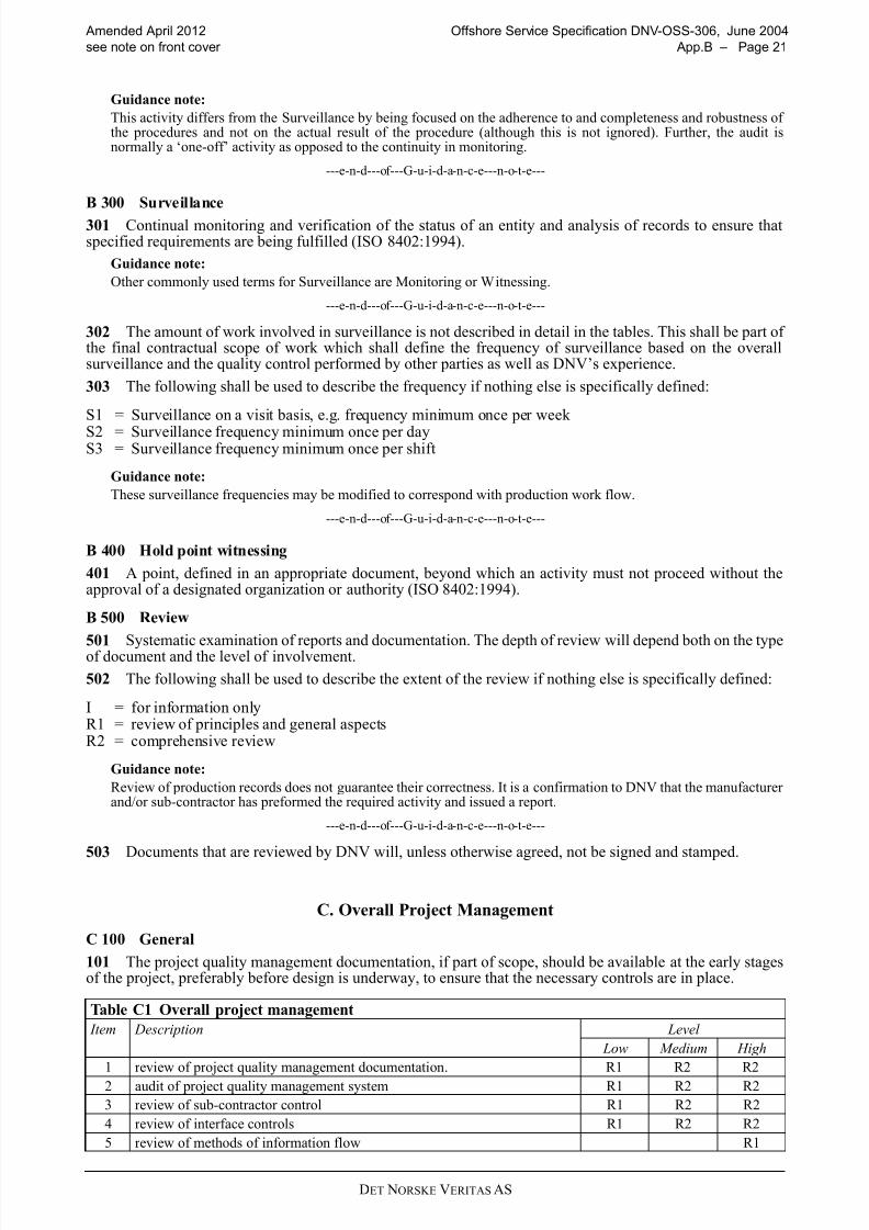
302 The amount of work involved in surveillance is not described in detail in the tables. This shall be part of the final contractual scope of work which shall define the frequency of surveillance based on the overallsurveillance and the quality control performed by other parties as well as DNV’s experience.
303 The following shall be used to describe the frequency if nothing else is specifically defined:
S1 = Surveillance on a visit basis, e.g. frequency minimum once per week
S2 = Surveillance frequency minimum once per dayS3 = Surveillance frequency minimum once per shift
Guidance note:
These surveillance frequencies may be modified to correspond with production work flow.
---e-n-d---of---G-u-i-d-a-n-c-e---n-o-t-e---
B 400 Hold point witnessing
401 A point, defined in an appropriate document, beyond which an activity must not proceed without theapproval of a designated organization or authority (ISO 8402:1994).
B 500 Review
501 Systematic examination of reports and documentation. The depth of review will depend both on the typeof document and the level of involvement.
502 The following shall be used to describe the extent of the review if nothing else is specifically defined:
I = for information onlyR1 = review of principles and general aspectsR2 = comprehensive review
Guidance note:
Review of production records does not guarantee their correctness. It is a confirmation to DNV that the manufacturer and/or sub-contractor has preformed the required activity and issued a report.
---e-n-d---of---G-u-i-d-a-n-c-e---n-o-t-e---
503 Documents that are reviewed by DNV will, unless otherwise agreed, not be signed and stamped.
C. Overall Project Management
C 100 General
101 The project quality management documentation, if part of scope, should be available at the early stagesof the project, preferably before design is underway, to ensure that the necessary controls are in place.
Table C1 Overall project management
Item Description Level
Low Medium High
1 review of project quality management documentation. R1 R2 R2
2 audit of project quality management system R1 R2 R2
3 review of sub-contractor control R1 R2 R2
4 review of interface controls R1 R2 R2
5 review of methods of information flow R1

8/10/2019 oss-306_2012-04
http://slidepdf.com/reader/full/oss-3062012-04 22/58DET NORSKE VERITAS AS
Offshore Service Specification DNV-OSS-306, June 2004 Amended April 2012
Page 22 – App.B see note on front cover
D. Design
D 100 General
101 For design verification a list similar to that given in Tables D1 to D10 shall be made for the specifics of the minimum requirement to documentation for each subsea facility.
D 200 Design Verification
201 Tables D1 to D10 describe issues to be verified. Tables D11 to D19 identifies relevant independentanalyses/calculations included in the three verification levels.
D 300 Low level Design Verification
301 The initial Low level design verification consists of a detailed document review of the design basis, risk assessment/analysis documentation, quality management documentation and (if they exist) method or design
philosophy documents. The presumed high risk aspects of the project shall be identified by DNV from theinitial review and conveyed to the Owner and designer for discussion and agreement on correct understanding.
302 The subsequent verification consists of document review of the calculations analysis methods used toconclude the high risk aspects. Other design documents are used as information and a few will be spot checkedfor confirmation of the quality control.
303 Implementation of the transfer of conclusions from design calculations and or reports into drawings and
specifications is not included.
D 400 Medium level Design Verification
401 Medium level design verification consists of a review of all main design documents related to subseafacilities safety and integrity. Less critical aspects will be spot checked. The review will be detailed for highrisk aspects and independent checks will be performed.
402 A design quality management system audit will be performed.
403 Implementation of the conclusions from design calculations/reports into drawings and specifications will be or is included on a spot check basis.
D 500 High level Design Verification
501 High level design verification consists of a full review of most of the produced documents related tointegrity. The review will be detailed for all high risk aspects and independent checks shall be performed.
502 Implementation of the conclusions from design calculations reports into drawings and specifications isincluded.
503 The main specifications are also checked for clearness and ambiguity.
Table D1 Subsea production system design
Item Description Level
Low Med. High
General
Availability/reliability of the systems:
1 System RAM analysis I R1 R2
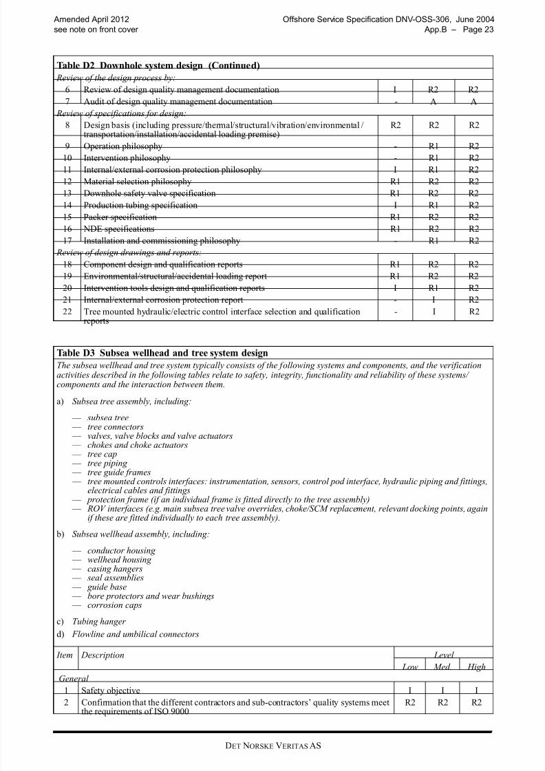
Table D2 Downhole system design
The downhole system typically consists of the following systems and components, and the verification activities describedin the following tables relate to safety, integrity, functionality and reliability of these systems/ components and theinteraction between them.
— Downhole safety valve — Production tubing — Packer
Item Description Level
Low Med. High
General
1 Safety objective I I I
2 Confirmation that the different contractors and sub-contractors’ quality systemsmeet the requirements of ISO 9000 R2 R2 R2
3 Description of subsea system and overall project organisation I I R1
4 Risk assessment and identification of critical aspects R2 R2 R2
5 Document register I R1 R2
8/10/2019 oss-306_2012-04
http://slidepdf.com/reader/full/oss-3062012-04 23/58DET NORSKE VERITAS AS
Amended April 2012 Offshore Service Specification DNV-OSS-306, June 2004
see note on front cover App.B – Page 23
Review of the design process by:
6 Review of design quality management documentation I R2 R2
7 Audit of design quality management documentation - A A
Review of specifications for design:
8 Design basis (including pressure/thermal/structural/vibration/environmental /
transportation/installation/accidental loading premise)
R2 R2 R2
9 Operation philosophy - R1 R2
10 Intervention philosophy - R1 R2
11 Internal/external corrosion protection philosophy I R1 R2
12 Material selection philosophy R1 R2 R2
13 Downhole safety valve specification R1 R2 R2
14 Production tubing specification I R1 R2
15 Packer specification R1 R2 R2
16 NDE specifications R1 R2 R2
17 Installation and commissioning philosophy - R1 R2
Review of design drawings and reports:
18 Component design and qualification reports R1 R2 R2
19 Environmental/structural/accidental loading report R1 R2 R2
20 Intervention tools design and qualification reports I R1 R2
21 Internal/external corrosion protection report - I R2
22 Tree mounted hydraulic/electric control interface selection and qualificationreports
- I R2
Table D3 Subsea wellhead and tree system design
The subsea wellhead and tree system typically consists of the following systems and components, and the verificationactivities described in the following tables relate to safety, integrity, functionality and reliability of these systems/components and the interaction between them.
a) Subsea tree assembly, including: — subsea tree — tree connectors — valves, valve blocks and valve actuators — chokes and choke actuators — tree cap — tree piping — tree guide frames — tree mounted controls interfaces: instrumentation, sensors, control pod interface, hydraulic piping and fittings,
electrical cables and fittings — protection frame (if an individual frame is fitted directly to the tree assembly) — ROV interfaces (e.g. main subsea tree valve overrides, choke/SCM replacement, relevant docking points, again
if these are fitted individually to each tree assembly).
b) Subsea wellhead assembly, including:
— conductor housing — wellhead housing — casing hangers — seal assemblies — guide base — bore protectors and wear bushings — corrosion caps
c) Tubing hanger
d) Flowline and umbilical connectors
Item Description Level
Low Med. High
General
1 Safety objective I I I
2 Confirmation that the different contractors and sub-contractors’ quality systems meetthe requirements of ISO 9000
R2 R2 R2
Table D2 Downhole system design (Continued)

8/10/2019 oss-306_2012-04
http://slidepdf.com/reader/full/oss-3062012-04 24/58DET NORSKE VERITAS AS
Offshore Service Specification DNV-OSS-306, June 2004 Amended April 2012
Page 24 – App.B see note on front cover
3 Description of subsea system and overall project organisation I I R1
4 Risk assessment and identification of critical aspects R2 R2 R2
5 Document register I R1 R2
Review of the design process by:
6 Review of design quality management documentation R2 R2 R2
7 Audit of design quality management documentation - A A Review of specifications for design:
8 Design basis (including pressure/thermal/structural/vibration/environmental /transportation/installation/accidental loading premise)
R2 R2 R2
9 Operation philosophy - R1 R2
10 Intervention philosophy - R1 R2
11 Internal/external corrosion protection philosophy I R1 R2
12 Material selection philosophy R1 R2 R2
13 Subsea tree and piping specification R1 R2 R2
14 Valve and actuator specifications R1 R1 R2
15 Choke and actuator specifications R1 R2 R2
16 Tree cap specifications R1 R2 R2
17 Tree guide frames specifications - - R1
18 Protection frame specifications - - R1
19 Tree mounted hydraulic/electric control interface specifications R1 R2 R2
20 Wellhead assembly specification R1 R2 R2
21 Tubing hanger specification R1 R2 R2
22 Flowline and umbilical connector specification I R1 R2
23 Manufacturing/inspection/test specifications R1 R2 R2
24 Welding procedure specifications R1 R2 R2
25 NDE specifications R1 R2 R2
26 Installation and commissioning philosophy - R1 R2
Review of design drawings and reports:
27 Component design and qualification reports R1 R2 R228 Environmental/structural/accidental loading report R1 R2 R2
29 Intervention tools design and qualification reports I R1 R2
30 Internal/external corrosion protection report - I R2
31 Tree mounted hydraulic/electric control interface selection and qualification reports - I R2
32 Installation analysis R1 R2 R2
Table D4 Manifold, foundations and template design
The Manifold, foundations and template system consists of the following sub-systems and components, and theverification activities described in the following tables relate to safety, integrity, functionality and reliability of these
systems/ components and the interaction between them.
— Manifold piping — Flowline connections — Isolation valves and actuators — Chemical injection valves and actuators (if applicable) — Production/Injection choke body, insert and actuator (if applicable) — Protection frame
ROV interfaces (e.g. valve overrides, choke/SCM replacement, and relevant docking points).
Item Description Level
Low Med. High
General
1 Safety objective I I I
2 Confirmation that the different contractors and sub-contractors’ quality systems meetthe requirements of ISO 9000 R2 R2 R2
3 Description of subsea system and overall project organisation I I R1
4 Risk assessment and identification of critical aspects R2 R2 R2
5 Document register I R1 R2
Table D3 Subsea wellhead and tree system design (Continued)

8/10/2019 oss-306_2012-04
http://slidepdf.com/reader/full/oss-3062012-04 25/58DET NORSKE VERITAS AS
Amended April 2012 Offshore Service Specification DNV-OSS-306, June 2004
see note on front cover App.B – Page 25
Review of the design process by:
6 Review of design quality management documentation R2 R2 R2
7 Audit of design quality management documentation - A A
Review of specifications for design:
8 Design basis (including pressure/thermal/structural/vibration/environmental /
transportation/installation/accidental loading premise)
R2 R2 R2
9 Operation philosophy - R1 R2
10 Intervention philosophy - R1 R2
11 Internal/external corrosion protection philosophy I R1 R2
12 Material selection philosophy R1 R2 R2
13 Manifold and piping specifications R1 R2 R2
14 Flowline connections specifications R1 R2 R2
15 Production/Injection choke body, insert and actuator specifications R1 R2 R2
16 Protection frame specifications R1 R2 R2
17 ROV interface specifications R1 R2 R2
18 Valve specifications R1 R2 R2
19 Actuator specifications R1 R2 R2
20 Instrumentation specifications I R1 R2
21 Manufacturing/inspection/test specifications R1 R2 R2
22 Welding procedure specifications R1 R2 R2
23 NDE specifications R1 R2 R2
24 Installation and commissioning philosophy - R1 R2
Review of design drawings and reports:
25 Design and qualification reports R1 R2 R2
26 Environmental/accidental loading report R1 R2 R2
27 Intervention tools design and qualification reports I R1 R2
28 Internal/external corrosion protection report - I R2
29 Valve selection and qualification reports R1 R2 R2
30 Actuator selection and qualification reports R1 R2 R231 Instrumentation selection and qualification reports - I R2
32 Foundation design report R1 R2 R2
33 Installation analysis R1 R2 R2
Table D4 Manifold, foundations and template design (Continued)

8/10/2019 oss-306_2012-04
http://slidepdf.com/reader/full/oss-3062012-04 26/58DET NORSKE VERITAS AS
Offshore Service Specification DNV-OSS-306, June 2004 Amended April 2012
Page 26 – App.B see note on front cover
Table D5 Flowlines and risers design
Flowlines and risers typically consist of the following applications, and the verification activities relate to safety,integrity, functionality and reliability of these applications.
a) Flowlines:
— Rigid flowlines — Rigid flowline tie-in spools (e.g. between wellheads and manifold, manifold and production installation) — Flexible flowlines
b) Rigid risers:
— Rigid metallic risers
c) Dynamic risers
— Dynamic metallic risers — Dynamic composite risers — Dynamic flexible risers — Dynamic umbilical risers
The detailed verification of the above components will performed according the following documents:
a) Flowlines: DNV-0SS-301, Certification and verification of pipelines.
b) Rigid risers: DNV-0SS-301, Certification and verification of pipelines.
c) Dynamic risers: DNV-0SS-302, Offshore riser systems.
Item Description Level
Low Med. High
General
1 Safety objective I I I
2 Confirmation that the different contractors and sub-contractors’ quality systems meetthe requirements of ISO 9000
R2 R2 R2
3 Description of subsea system and overall project organisation I I R1
4 Risk assessment and identification of critical aspects R2 R2 R2
5 Document register I R1 R2
8/10/2019 oss-306_2012-04
http://slidepdf.com/reader/full/oss-3062012-04 27/58DET NORSKE VERITAS AS
Amended April 2012 Offshore Service Specification DNV-OSS-306, June 2004
see note on front cover App.B – Page 27
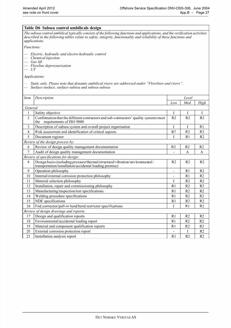
Table D6 Subsea control umbilicals design
The subsea control umbilical typically consists of the following functions and applications, and the verification activitiesdescribed in the following tables relate to safety, integrity, functionality and reliability of these functions andapplications.
Functions:
— Electric, hydraulic and electro-hydraulic control
— Chemical injection — Gas lift — Flowline depressurization — UT
Applications:
— Static only. Please note that dynamic umbilical risers are addressed under ”Flowlines and risers”. — Surface-surface, surface-subsea and subsea-subsea
Item Description Level
Low Med. High
General
1 Safety objective I I I
2 Confirmation that the different contractors and sub-contractors’ quality systems meetthe requirements of ISO 9000
R2 R2 R2
3 Description of subsea system and overall project organisation I I R1
4 Risk assessment and identification of critical aspects R2 R2 R2
5 Document register I R1 R2
Review of the design process by:
6 Review of design quality management documentation R2 R2 R2
7 Audit of design quality management documentation - A A
Review of specifications for design:
8 Design basis (including pressure/thermal/structural/vibration/environmental /transportation/installation/accidental loading premise)
R2 R2 R2
9 Operation philosophy - R1 R210 Internal/external corrosion protection philosophy - R1 R2
11 Material selection philosophy I R2 R2
12 Installation, repair and commissioning philosophy R1 R2 R2
13 Manufacturing/inspection/test specifications R1 R2 R2
14 Welding procedure specifications R1 R2 R2
15 NDE specifications R1 R2 R2
16 End connector/pull-in head/bend restrictor specifications I R1 R2
Review of design drawings and reports:
17 Design and qualification reports R1 R2 R2
18 Environmental/accidental loading report R1 R2 R2
19 Material and component qualification reports R1 R2 R2
20 External corrosion protection report - I R2
21 Installation analysis report R1 R2 R2
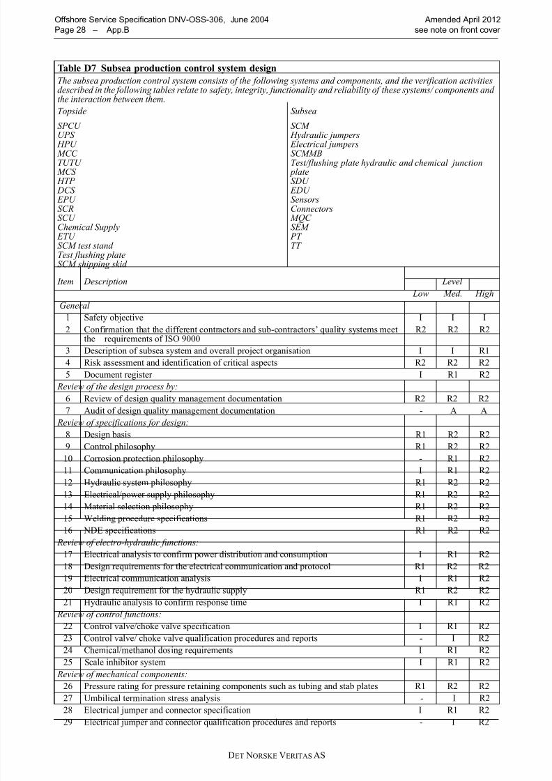
8/10/2019 oss-306_2012-04
http://slidepdf.com/reader/full/oss-3062012-04 28/58DET NORSKE VERITAS AS
Offshore Service Specification DNV-OSS-306, June 2004 Amended April 2012
Page 28 – App.B see note on front cover
Table D7 Subsea production control system design
The subsea production control system consists of the following systems and components, and the verification activitiesdescribed in the following tables relate to safety, integrity, functionality and reliability of these systems/ components andthe interaction between them.
Topside
SPCU
UPS HPU MCCTUTU
MCS HTP DCS EPU SCRSCU Chemical Supply
ETUSCM test standTest flushing plateSCM shipping skid
Subsea
SCM
Hydraulic jumpers Electrical jumpersSCMMBTest/flushing plate hydraulic and chemical junction
plateSDU
EDU SensorsConnectors
MQC SEM
PT TT
Item Description Level
Low Med. High
General
1 Safety objective I I I
2 Confirmation that the different contractors and sub-contractors’ quality systems meetthe requirements of ISO 9000
R2 R2 R2
3 Description of subsea system and overall project organisation I I R1
4 Risk assessment and identification of critical aspects R2 R2 R2
5 Document register I R1 R2
Review of the design process by:
6 Review of design quality management documentation R2 R2 R2
7 Audit of design quality management documentation - A A Review of specifications for design:
8 Design basis R1 R2 R2
9 Control philosophy R1 R2 R2
10 Corrosion protection philosophy - R1 R2
11 Communication philosophy I R1 R2
12 Hydraulic system philosophy R1 R2 R2
13 Electrical/power supply philosophy R1 R2 R2
14 Material selection philosophy R1 R2 R2
15 Welding procedure specifications R1 R2 R2
16 NDE specifications R1 R2 R2
Review of electro-hydraulic functions:
17 Electrical analysis to confirm power distribution and consumption I R1 R2
18 Design requirements for the electrical communication and protocol R1 R2 R2
19 Electrical communication analysis I R1 R2
20 Design requirement for the hydraulic supply R1 R2 R2
21 Hydraulic analysis to confirm response time I R1 R2
Review of control functions:
22 Control valve/choke valve specification I R1 R2
23 Control valve/ choke valve qualification procedures and reports - I R2
24 Chemical/methanol dosing requirements I R1 R2
25 Scale inhibitor system I R1 R2
Review of mechanical components:
26 Pressure rating for pressure retaining components such as tubing and stab plates R1 R2 R227 Umbilical termination stress analysis - I R2
28 Electrical jumper and connector specification I R1 R2
29 Electrical jumper and connector qualification procedures and reports - I R2
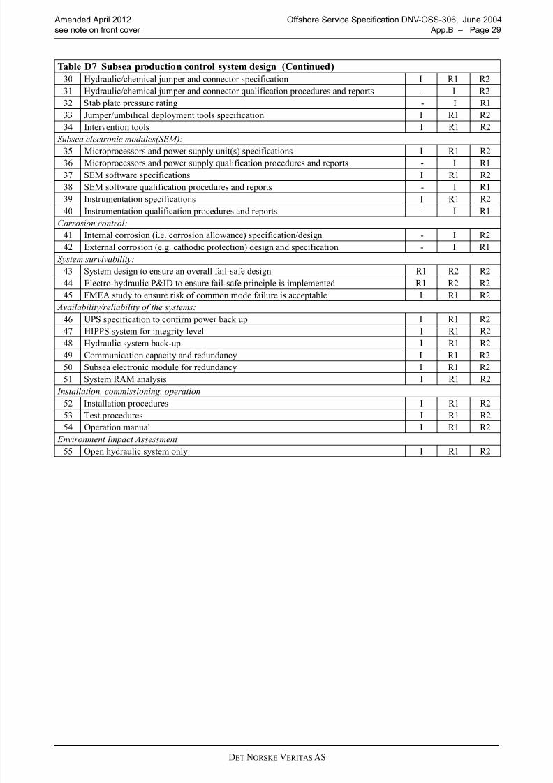
8/10/2019 oss-306_2012-04
http://slidepdf.com/reader/full/oss-3062012-04 29/58DET NORSKE VERITAS AS
Amended April 2012 Offshore Service Specification DNV-OSS-306, June 2004
see note on front cover App.B – Page 29
30 Hydraulic/chemical jumper and connector specification I R1 R2
31 Hydraulic/chemical jumper and connector qualification procedures and reports - I R2
32 Stab plate pressure rating - I R1
33 Jumper/umbilical deployment tools specification I R1 R2
34 Intervention tools I R1 R2
Subsea electronic modules(SEM):35 Microprocessors and power supply unit(s) specifications I R1 R2
36 Microprocessors and power supply qualification procedures and reports - I R1
37 SEM software specifications I R1 R2
38 SEM software qualification procedures and reports - I R1
39 Instrumentation specifications I R1 R2
40 Instrumentation qualification procedures and reports - I R1
Corrosion control:
41 Internal corrosion (i.e. corrosion allowance) specification/design - I R2
42 External corrosion (e.g. cathodic protection) design and specification - I R1
System survivability:
43 System design to ensure an overall fail-safe design R1 R2 R244 Electro-hydraulic P&ID to ensure fail-safe principle is implemented R1 R2 R2
45 FMEA study to ensure risk of common mode failure is acceptable I R1 R2
Availability/reliability of the systems:
46 UPS specification to confirm power back up I R1 R2
47 HIPPS system for integrity level I R1 R2
48 Hydraulic system back-up I R1 R2
49 Communication capacity and redundancy I R1 R2
50 Subsea electronic module for redundancy I R1 R2
51 System RAM analysis I R1 R2
Installation, commissioning, operation
52 Installation procedures I R1 R2
53 Test procedures I R1 R2
54 Operation manual I R1 R2
Environment Impact Assessment
55 Open hydraulic system only I R1 R2
Table D7 Subsea production control system design (Continued)
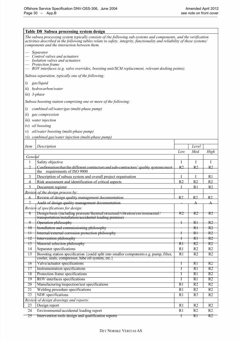
8/10/2019 oss-306_2012-04
http://slidepdf.com/reader/full/oss-3062012-04 30/58
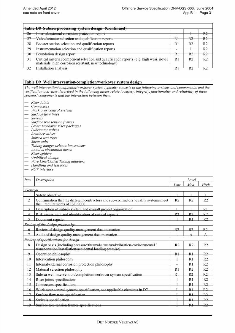
8/10/2019 oss-306_2012-04
http://slidepdf.com/reader/full/oss-3062012-04 31/58DET NORSKE VERITAS AS
Amended April 2012 Offshore Service Specification DNV-OSS-306, June 2004
see note on front cover App.B – Page 31
26 Internal/external corrosion protection report - I R2
27 Valve/actuator selection and qualification reports R1 R2 R2
28 Booster station selection and qualification reports R1 R2 R2
29 Instrumentation selection and qualification reports - I R2
30 Foundation design report R1 R2 R2
31 Critical material/component selection and qualification reports {e.g. high wear, novelmaterials, high corrosion resistant, new technology}
R1 R2 R2
32 Installation analysis R1 R2 R2
Table D9 Well intervention/completion/workover system design
The well intervention/completion/workover system typically consists of the following systems and components, and theverification activities described in the following tables relate to safety, integrity, functionality and reliability of these
systems/ components and the interaction between them.
— Riser joints — Connectors — Work over control systems — Surface flow trees — Swivels — Surface tree tension frames — Lower workover riser packages — Lubricator valves — Retainer valves — Subsea test trees — Shear subs — Tubing hanger orientation systems — Annulus circulation hoses — Riser spiders — Umbilical clamps — Wire Line/Coiled Tubing adapters — Handling and test tools — ROV interface
Item Description Level
Low Med. High
General
1 Safety objective I I I
2 Confirmation that the different contractors and sub-contractors’ quality systems meetthe requirements of ISO 9000
R2 R2 R2
3 Description of subsea system and overall project organization I I R1
4 Risk assessment and identification of critical aspects R2 R2 R2
5 Document register I R1 R2
Review of the design process by:
6 Review of design quality management documentation R2 R2 R2
7 Audit of design quality management documentation - A A
Review of specifications for design:
8 Design basis (including pressure/thermal/structural/vibration/environmental /transportation/installation/accidental loading premise)
R2 R2 R2
9 Operation philosophy R1 R1 R2
10 Intervention philosophy I R1 R2
11 Internal/external corrosion protection philosophy - R1 R2
12 Material selection philosophy R1 R2 R2
13 Subsea well intervention/completion/workover system specification R1 R2 R2
14 Riser joints specifications I R1 R2
15 Connectors specifications I R1 R2
16 Work over control systems specification, see applicable elements in D7 I R1 R217 Surface flow trees specification I R1 R2
18 Swivels specification I R1 R2
19 Surface tree tension frames specifications I R1 R2
Table D8 Subsea processing system design (Continued)
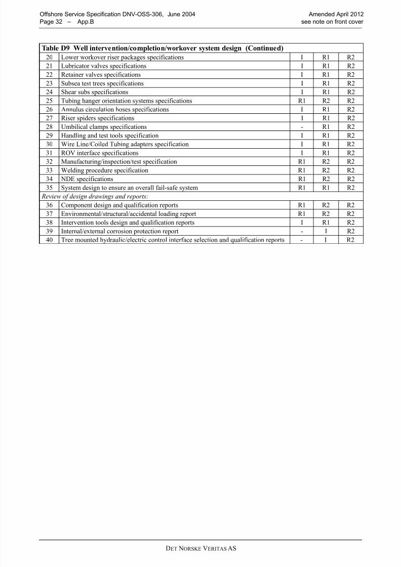
8/10/2019 oss-306_2012-04
http://slidepdf.com/reader/full/oss-3062012-04 32/58DET NORSKE VERITAS AS
Offshore Service Specification DNV-OSS-306, June 2004 Amended April 2012
Page 32 – App.B see note on front cover
20 Lower workover riser packages specifications I R1 R2
21 Lubricator valves specifications I R1 R2
22 Retainer valves specifications I R1 R2
23 Subsea test trees specifications I R1 R2
24 Shear subs specifications I R1 R2
25 Tubing hanger orientation systems specifications R1 R2 R226 Annulus circulation hoses specifications I R1 R2
27 Riser spiders specifications I R1 R2
28 Umbilical clamps specifications - R1 R2
29 Handling and test tools specification I R1 R2
30 Wire Line/Coiled Tubing adapters specification I R1 R2
31 ROV interface specifications I R1 R2
32 Manufacturing/inspection/test specification R1 R2 R2
33 Welding procedure specification R1 R2 R2
34 NDE specifications R1 R2 R2
35 System design to ensure an overall fail-safe system R1 R1 R2
Review of design drawings and reports:36 Component design and qualification reports R1 R2 R2
37 Environmental/structural/accidental loading report R1 R2 R2
38 Intervention tools design and qualification reports I R1 R2
39 Internal/external corrosion protection report - I R2
40 Tree mounted hydraulic/electric control interface selection and qualification reports - I R2
Table D9 Well intervention/completion/workover system design (Continued)
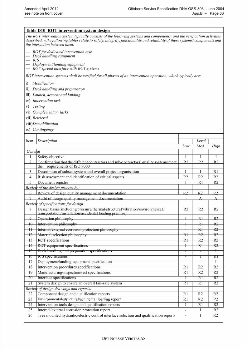
8/10/2019 oss-306_2012-04
http://slidepdf.com/reader/full/oss-3062012-04 33/58DET NORSKE VERITAS AS
Amended April 2012 Offshore Service Specification DNV-OSS-306, June 2004
see note on front cover App.B – Page 33
Table D10 ROT intervention system design
The ROT intervention system typically consists of the following systems and components, and the verification activitiesdescribed in the following tables relate to safety, integrity, functionality and reliability of these systems/ components andthe interaction between them.
— ROT for dedicated intervention task — Deck handling equipment
— ICS — Deployment/landing equipment — ROV spread interface with ROT systems
ROT intervention systems shall be verified for all phases of an intervention operation, which typically are:
i) Mobilization
ii) Deck handling and preparation
iii) Launch, descent and landing
iv) Intervention task
v) Testing
vi) Complementary tasks
vii) Retrieval
viii) Demobilization
ix) Contingency
Item Description Level
Low Med. High
General
1 Safety objective I I I
2 Confirmation that the different contractors and sub-contractors’ quality systems meetthe requirements of ISO 9000
R2 R2 R2
3 Description of subsea system and overall project organisation I I R1
4 Risk assessment and identification of critical aspects R2 R2 R2
5 Document register I R1 R2 Review of the design process by:
6 Review of design quality management documentation R2 R2 R2
7 Audit of design quality management documentation - A A
Review of specifications for design:
8 Design basis (including pressure/thermal/structural/vibration/environmental /transportation/installation/accidental loading premise)
R2 R2 R2
9 Operation philosophy I R1 R2
10 Intervention philosophy I R1 R2
11 Internal/external corrosion protection philosophy - R1 R2
12 Material selection philosophy R1 R2 R2
13 ROT specifications R1 R2 R2
14 ROT equipment specifications I R1 R215 Deck handling and preparation specifications - - I
16 ICS specifications - I R1
17 Deployment/landing equipment specification - - I
18 Intervention procedures specifications R1 R2 R2
19 Manufacturing/inspection/test specifications R1 R2 R2
20 Interface specifications I R1 R2
21 System design to ensure an overall fail-safe system R1 R1 R2
Review of design drawings and reports:
22 Component design and qualification reports R1 R2 R2
23 Environmental/structural/accidental loading report R1 R2 R2
24 Intervention tools design and qualification reports I R1 R225 Internal/external corrosion protection report - I R2
26 Tree mounted hydraulic/electric control interface selection and qualification reports - I R2
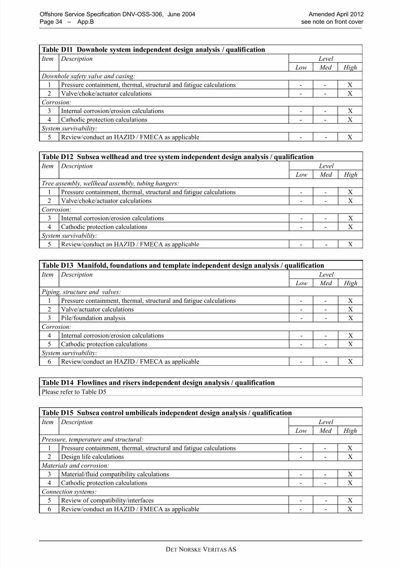
8/10/2019 oss-306_2012-04
http://slidepdf.com/reader/full/oss-3062012-04 34/58DET NORSKE VERITAS AS
Offshore Service Specification DNV-OSS-306, June 2004 Amended April 2012
Page 34 – App.B see note on front cover
Table D11 Downhole system independent design analysis / qualification
Item Description Level
Low Med High
Downhole safety valve and casing:
1 Pressure containment, thermal, structural and fatigue calculations - - X
2 Valve/choke/actuator calculations - - X
Corrosion:
3 Internal corrosion/erosion calculations - - X
4 Cathodic protection calculations - - X
System survivability:
5 Review/conduct an HAZID / FMECA as applicable - - X
Table D12 Subsea wellhead and tree system independent design analysis / qualification
Item Description Level
Low Med High
Tree assembly, wellhead assembly, tubing hangers:
1 Pressure containment, thermal, structural and fatigue calculations - - X
2 Valve/choke/actuator calculations - - X
Corrosion:
3 Internal corrosion/erosion calculations - - X
4 Cathodic protection calculations - - X
System survivability:
5 Review/conduct an HAZID / FMECA as applicable - - X
Table D13 Manifold, foundations and template independent design analysis / qualification
Item Description Level
Low Med High
Piping, structure and valves:
1 Pressure containment, thermal, structural and fatigue calculations - - X
2 Valve/actuator calculations - - X
3 Pile/foundation analysis - - X
Corrosion:
4 Internal corrosion/erosion calculations - - X
5 Cathodic protection calculations - - X
System survivability:
6 Review/conduct an HAZID / FMECA as applicable - - X
Table D14 Flowlines and risers independent design analysis / qualification
Please refer to Table D5
Table D15 Subsea control umbilicals independent design analysis / qualification
Item Description Level
Low Med High
Pressure, temperature and structural:
1 Pressure containment, thermal, structural and fatigue calculations - - X
2 Design life calculations - - X
Materials and corrosion:
3 Material/fluid compatibility calculations - - X
4 Cathodic protection calculations - - X
Connection systems:
5 Review of compatibility/interfaces - - X
6 Review/conduct an HAZID / FMECA as applicable - - X

8/10/2019 oss-306_2012-04
http://slidepdf.com/reader/full/oss-3062012-04 35/58DET NORSKE VERITAS AS
Amended April 2012 Offshore Service Specification DNV-OSS-306, June 2004
see note on front cover App.B – Page 35
Table D16 Subsea production control system independent design analysis / qualification
Item Description Level
Low Med High
Electro-hydraulic functions:
1 Pressure containment, thermal, structural and fatigue calculations - - X
2 Tree/choke/chemical injection valve/actuator calculations - - X
3 Independent electrical communication analysis to confirm communication time - - X
Control functions:
4 Calculation for dosing requirement - - X
5 Control valve/ choke valve qualification - - X
Mechanical components:
6 Umbilical termination stress analysis - - X
7 Electrical jumper and connector qualification - - X
8 Hydraulic/chemical jumper and connector qualification - - X
9 Stab plate qualification - - X
10 Jumper/umbilical deployment tools qualification - - X
11 Intervention tools qualification - - X
Subsea electronic modules (SEM):12 Microprocessors and power supply qualification - - X
13 SEM software qualification - - X
14 Instrumentation qualification - - X
Corrosion:
15 Calculation of cathodic protection - - X
System survivability:
16 Review/conduct an HAZID / FMECA as applicable - - X
Table D17 Subsea processing system independent design analysis / qualification
Item Description Level
Low Med HighSeparators, rotating equipment and valves:
1 Pressure containment, thermal, structural and fatigue calculations - - X
2 Pump/compressor mechanics/fluid dynamics - - X
3 Valve/actuator calculations - - X
Corrosion:
4 Internal corrosion/erosion calculations - - X
5 Cathodic protection calculations - - X
System survivability:
6 Review/conduct an HAZID / FMECA as applicable - - X
Table D18 Well intervention/completion/workover system independent design analysis / qualification Item Description Level
Low Med High
Well intervention/completion/workover assembly:
1 Pressure containment, thermal, structural and fatigue calculations - - X
2 Valve/choke/actuator calculations - - X
Mechanical components
3 Umbilical analysis see D15
4 Workover control system analysis see D16
Corrosion:
5 Internal corrosion/erosion calculations - - X
6 Cathodic protection calculations - - X
System survivability:
7 Review/conduct an HAZID / FMECA as applicable - - X
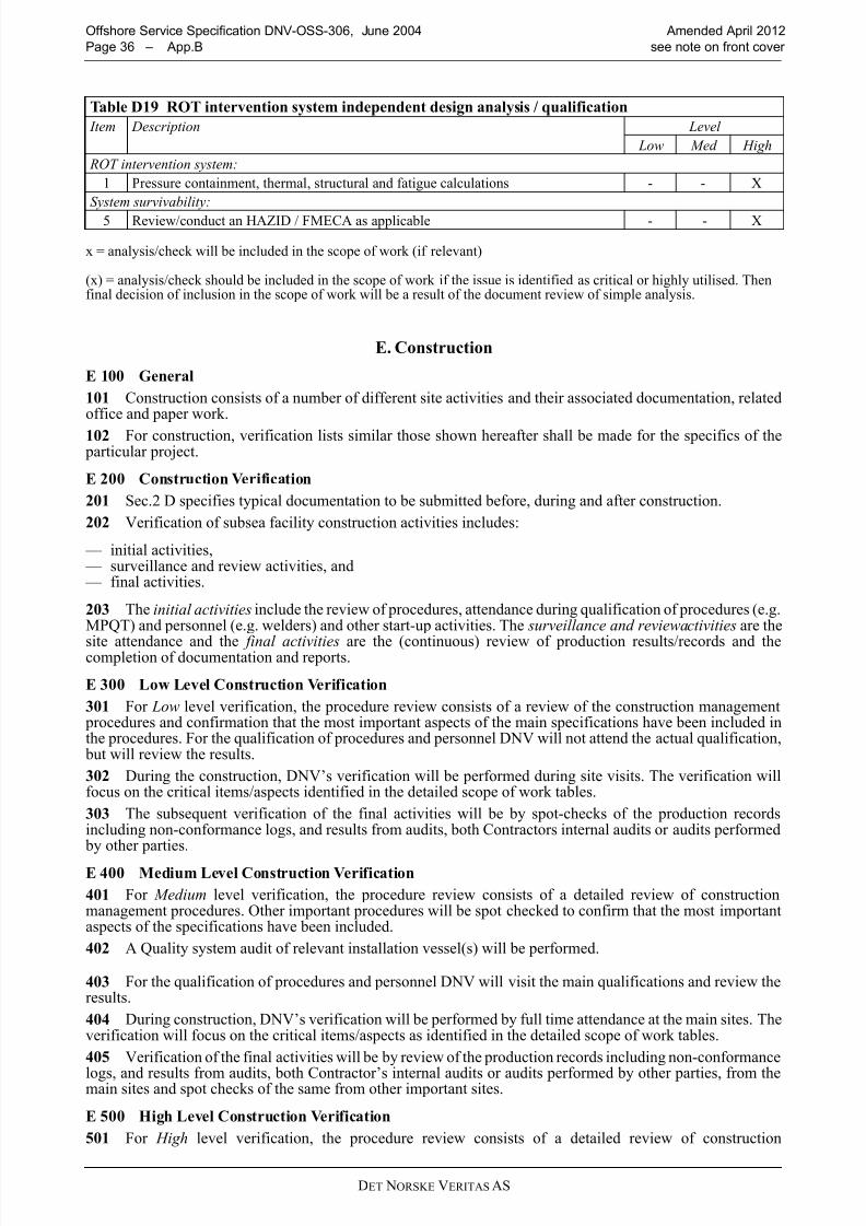
8/10/2019 oss-306_2012-04
http://slidepdf.com/reader/full/oss-3062012-04 36/58DET NORSKE VERITAS AS
Offshore Service Specification DNV-OSS-306, June 2004 Amended April 2012
Page 36 – App.B see note on front cover
E. Construction
E 100 General
101 Construction consists of a number of different site activities and their associated documentation, relatedoffice and paper work.
102 For construction, verification lists similar those shown hereafter shall be made for the specifics of the particular project.
E 200 Construction Verification
201 Sec.2 D specifies typical documentation to be submitted before, during and after construction.
202 Verification of subsea facility construction activities includes:
— initial activities, — surveillance and review activities, and — final activities.
203 The initial activities include the review of procedures, attendance during qualification of procedures (e.g.MPQT) and personnel (e.g. welders) and other start-up activities. The surveillance and reviewactivities are the
site attendance and the final activities are the (continuous) review of production results/records and thecompletion of documentation and reports.
E 300 Low Level Construction Verification
301 For Low level verification, the procedure review consists of a review of the construction management procedures and confirmation that the most important aspects of the main specifications have been included inthe procedures. For the qualification of procedures and personnel DNV will not attend the actual qualification,
but will review the results.
302 During the construction, DNV’s verification will be performed during site visits. The verification willfocus on the critical items/aspects identified in the detailed scope of work tables.
303 The subsequent verification of the final activities will be by spot-checks of the production recordsincluding non-conformance logs, and results from audits, both Contractors internal audits or audits performed
by other parties.
E 400 Medium Level Construction Verification
401 For Medium level verification, the procedure review consists of a detailed review of constructionmanagement procedures. Other important procedures will be spot checked to confirm that the most importantaspects of the specifications have been included.
402 A Quality system audit of relevant installation vessel(s) will be performed.
403 For the qualification of procedures and personnel DNV will visit the main qualifications and review theresults.
404 During construction, DNV’s verification will be performed by full time attendance at the main sites. Theverification will focus on the critical items/aspects as identified in the detailed scope of work tables.
405 Verification of the final activities will be by review of the production records including non-conformance
logs, and results from audits, both Contractor’s internal audits or audits performed by other parties, from themain sites and spot checks of the same from other important sites.
E 500 High Level Construction Verification
501 For High level verification, the procedure review consists of a detailed review of construction
Table D19 ROT intervention system independent design analysis / qualification
Item Description Level
Low Med High
ROT intervention system:
1 Pressure containment, thermal, structural and fatigue calculations - - X
System survivability:
5 Review/conduct an HAZID / FMECA as applicable - - X
x = analysis/check will be included in the scope of work (if relevant)
(x) = analysis/check should be included in the scope of work if the issue is identified as critical or highly utilised. Thenfinal decision of inclusion in the scope of work will be a result of the document review of simple analysis.
8/10/2019 oss-306_2012-04
http://slidepdf.com/reader/full/oss-3062012-04 37/58DET NORSKE VERITAS AS
Amended April 2012 Offshore Service Specification DNV-OSS-306, June 2004
see note on front cover App.B – Page 37
management procedures. Other procedures will be spot checked to confirmation that important aspects of thespecifications have been included.
502 A Quality system audit of relevant installation vessel(s) will be performed.
503 For qualification of procedures and personnel DNV will attend the main qualifications, visit other qualifications and review the results.
504 During construction, DNV’s verification will be performed by full time attendance at the main sites and
by visits to the other important sites. Verification will focus on the critical items/aspects as identified in thedetailed scope of work tables.
505 Verification of the final activities will be by detailed review of manufacturing records, installationrecords, test results, non-conformance logs and relevant audit findings.
E 600 Verification of Work in Progress
601 The monitoring by the Owner during construction relates to the activities of the contractor. Themonitoring of these activities by DNV relates not only to the contractor’s activities but also to the monitoringof these activities carried out by the Owner.
602 The emphasis placed on the various activities in the verification plan varies depending on:
— any areas of concern revealed during design verification, — any areas of concern revealed during the audit of the Owner’s or contractor’s quality management systems,
— the progress of design or construction, — the findings of the contractor surveillance personnel.
603 Many contractors have adequate quality control systems and quality control departments, withcompetent personnel to perform required assessments of suppliers and sub-contractors.
604 In such a case, all verification work need not be done by DNV personnel. Where applicable, the variousinspections may be carried out by competent persons other than DNV personnel. In that situation DNV’sverification activities can be confined to:
— reviewing the competence of the Contractor’s personnel, — auditing their working methods and their performance of that work, and — reviewing the documents produced by them.
605 DNV personnel will spend more time in areas where problems have occurred, or are considered likely to
occur. Conversely, less time is spent in areas where the likelihood of problems is considered lower.
E 700 DNV Final Report
701 All the Scopes of Work tables for construction end with a Point entitled “Issue of DNV Visit Report”.This item is not related to the production process is intended as a reminder to the DNV (or others) inspection
personnel that a final report of their verification activities is required to finish the work.

8/10/2019 oss-306_2012-04
http://slidepdf.com/reader/full/oss-3062012-04 38/58DET NORSKE VERITAS AS
Offshore Service Specification DNV-OSS-306, June 2004 Amended April 2012
Page 38 – App.B see note on front cover
Table E1 Downhole system fabrication, manufacturing, sub-unit / unit and integration testing
Item Description Level
Low Med High
Initial activities
1 Review quality management system R2 R2 R2
2 Quality system audit at relevant manufacturers and sub-suppliers - A A
3 Review of specifications and procedures R1 R2 R24 Technical / kick-off meeting and review of manufacturers documents R1 R1 R2
5 Verify the performance and testing during the procedure and personnel qualificationtesting.
R1 S1 H
Surveillance and review activities
6 Confirm items manufactured according to specifications:
— review manufacturing records are in accordance with manufacturing quality planand relevant specifications/procedures
— review non-conformance logs
R1 R2 R2
7 Confirm valve functions by:
— witness FAT on all valve functions
S2 S3 S3
9 Confirm cleanliness of hydraulic systems by:
— review of cleanliness report
I R1 R2
10 Confirm pressure integrity of components by:
— review of pressure test certificates for each component
R1 R2 R2
11 Confirm corrosion control by:
— correct application of paint systems — inspection of anode locations in accordance with approved drawings
S1 S2 S3
12 Confirm correct markings by:
— inspection of markings in accordance with approved drawings — correct application of paint systems
S1 S2 S2
13 Confirm correct system function. Monitor Factory Acceptance Tests (FAT) with particular attention to:
— pressure tests — structural loading tests — valve operation — integration with control system — hydraulic fitness
S1 S3 S3
14 Confirm correct integration with subsea tools and equipment. Monitor SystemIntegration Tests (SIT) with particular attention to:
— systems assembly/fit-up — well intervention tool interfacing — integration with Subsea Control System
S1 S2 S3
Final activities
15 Confirm downhole system functions by review of:
— FAT records
I R1 R2
16 Confirm integration with subsea tools and equipment by review of:
— SIT reports
I R1 R2
17 Issue DNV visit / close-out report H H H
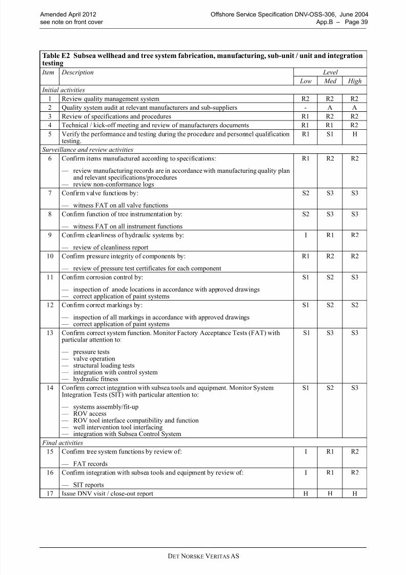
8/10/2019 oss-306_2012-04
http://slidepdf.com/reader/full/oss-3062012-04 39/58
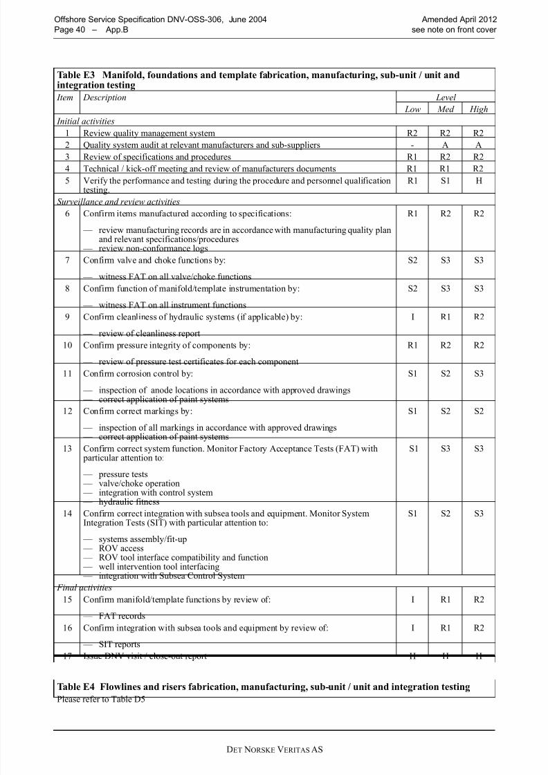
8/10/2019 oss-306_2012-04
http://slidepdf.com/reader/full/oss-3062012-04 40/58DET NORSKE VERITAS AS
Offshore Service Specification DNV-OSS-306, June 2004 Amended April 2012
Page 40 – App.B see note on front cover
Table E3 Manifold, foundations and template fabrication, manufacturing, sub-unit / unit andintegration testing
Item Description Level
Low Med High
Initial activities
1 Review quality management system R2 R2 R22 Quality system audit at relevant manufacturers and sub-suppliers - A A
3 Review of specifications and procedures R1 R2 R2
4 Technical / kick-off meeting and review of manufacturers documents R1 R1 R2
5 Verify the performance and testing during the procedure and personnel qualificationtesting.
R1 S1 H
Surveillance and review activities
6 Confirm items manufactured according to specifications:
— review manufacturing records are in accordance with manufacturing quality planand relevant specifications/procedures
— review non-conformance logs
R1 R2 R2
7 Confirm valve and choke functions by:
— witness FAT on all valve/choke functions
S2 S3 S3
8 Confirm function of manifold/template instrumentation by:
— witness FAT on all instrument functions
S2 S3 S3
9 Confirm cleanliness of hydraulic systems (if applicable) by:
— review of cleanliness report
I R1 R2
10 Confirm pressure integrity of components by:
— review of pressure test certificates for each component
R1 R2 R2
11 Confirm corrosion control by:
— inspection of anode locations in accordance with approved drawings — correct application of paint systems
S1 S2 S3
12 Confirm correct markings by:
— inspection of all markings in accordance with approved drawings — correct application of paint systems
S1 S2 S2
13 Confirm correct system function. Monitor Factory Acceptance Tests (FAT) with particular attention to:
— pressure tests — valve/choke operation — integration with control system — hydraulic fitness
S1 S3 S3
14 Confirm correct integration with subsea tools and equipment. Monitor SystemIntegration Tests (SIT) with particular attention to:
— systems assembly/fit-up — ROV access — ROV tool interface compatibility and function — well intervention tool interfacing — integration with Subsea Control System
S1 S2 S3
Final activities
15 Confirm manifold/template functions by review of:
— FAT records
I R1 R2
16 Confirm integration with subsea tools and equipment by review of:
— SIT reports
I R1 R2
17 Issue DNV visit / close-out report H H H
Table E4 Flowlines and risers fabrication, manufacturing, sub-unit / unit and integration testing
Please refer to Table D5

8/10/2019 oss-306_2012-04
http://slidepdf.com/reader/full/oss-3062012-04 41/58DET NORSKE VERITAS AS
Amended April 2012 Offshore Service Specification DNV-OSS-306, June 2004
see note on front cover App.B – Page 41
Table E5 Subsea control umbilicals manufacturing, sub-unit / unit and integration testing
Item Description Level
Low Med High
Initial activities
1 Review quality management system R2 R2 R2
2 Quality system audit at relevant manufacturers and sub-suppliers - A A
3 Review of specifications and procedures R1 R2 R2
4 Technical / kick-off meeting and review of manufacturers documents R1 R1 R2
5 Verify the performance and testing during the procedure and personnel qualificationtesting.
R1 S1 H
Surveillance and review activities
6 Confirm items manufactured according to specifications:
— review manufacturing records are in accordance with manufacturing quality planand relevant specifications/procedures
— review non-conformance logs
R1 R2 R2
7 Confirm critical dimensions. R1 R2 R2
8 Confirm cleanliness of hydraulic systems by:
— review of cleanliness report
I R1 R2
9 Confirm pressure integrity of components by:
— review of pressure test certificates for each component
R1 R2 R2
10 Confirm corrosion control by:
— inspection of anode locations in accordance with approved drawings — correct application of paint systems
S1 S2 S3
11 Confirm correct markings by:
— correct application of paint systems — inspection of all markings in accordance with approved drawings
S1 S2 S2
12 Confirm correct system function. Monitor Factory Acceptance Tests (FAT) with particular attention to:
— pressure tests — electrical tests for power and signal cables — integration with control system — hydraulic fitness
S1 S3 S3
Final activities
13 Confirm manifold/template functions by review of:
— FAT records
I R1 R2
14 Issue DNV visit / close-out report H H H
Table E6 Subsea production control system fabrication, manufacturing, sub-unit / unit andintegration testing
Item Description Level Low Med High
Initial activities
1 Review quality management system R2 R2 R2
2 Quality system audit at relevant manufacturers and sub-suppliers - - A
3 Review of specifications and procedures R1 R2 R2
4 Technical / kick-off meeting and review of manufacturers documents R1 R1 R2
5 Verify the performance and testing during the procedure and personnel qualificationtesting.
R1 S1 H
Surveillance and review activities
6 Confirm items manufactured according to specifications:
— review manufacturing records are in accordance with manufacturing quality planand relevant specifications/procedures — review non-conformance logs
R1 R2 R2

8/10/2019 oss-306_2012-04
http://slidepdf.com/reader/full/oss-3062012-04 42/58DET NORSKE VERITAS AS
Offshore Service Specification DNV-OSS-306, June 2004 Amended April 2012
Page 42 – App.B see note on front cover
7 Confirm subsea ESD process safety functions by:
— witness FAT on all ESD functions to ensure that fail-safe conditions are met
S3 S3 S3
8 Confirm capacity of UPS and hydraulic accumulator by:
— review of UPS and accumulator certificates
I R1 R2
9 Confirm cleanliness of hydraulic systems by:
— review of cleanliness report
I R1 R2
10 Confirm pressure integrity of components by:
— review of pressure test certificates for each component
I R1 R2
11 Confirm corrosion control by:
— inspection of anode locations in accordance with approved drawings — correct application of paint systems
S1 S2 S3
12 Confirm correct markings by:
— tag numbers — delivery protocol — non-conformity records
R1 R2 R2
13 Confirm correct system function. Monitor Factory Acceptance Tests (FAT) with particular attention to:
— power-up — software operating system — communication — redundancy test and smooth change-over — signal response time — electrical continuity — hydraulic fitness — valve operations
— choke position monitoring — DHPT monitoring
S1 S2 S3
14 Confirm correct integration with subsea control system equipment. Extended FactoryAcceptance Tests (EFAT) with particular attention to:
— systems assembly/fit-up — integration with subsea control system components
S1 S2 S3
15 Confirm correct integration with subsea tools and equipment. Monitor SystemIntegration Tests (SIT) with particular attention to:
— systems assembly/fit-up — ROV tool interface compatibility and function — integration with subsea tree/manifold/ processing systems where applicable
S1 S2 S3
Final activities
16 Confirm control system functions by review of:
— FAT records
I R1 R2
17 Confirm integration with subsea tools and equipment by review of:
— SIT reports
I R1 R2
18 Issue DNV visit / close-out report H H H
Table E6 Subsea production control system fabrication, manufacturing, sub-unit / unit andintegration testing (Continued)
Item Description Level
Low Med High
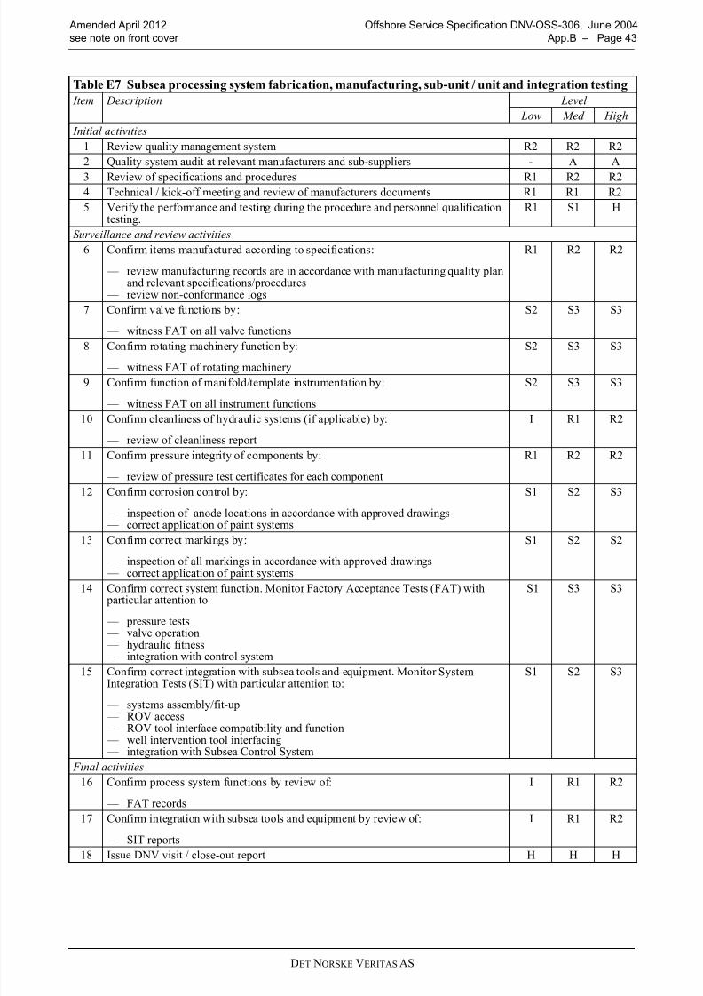
8/10/2019 oss-306_2012-04
http://slidepdf.com/reader/full/oss-3062012-04 43/58DET NORSKE VERITAS AS
Amended April 2012 Offshore Service Specification DNV-OSS-306, June 2004
see note on front cover App.B – Page 43
Table E7 Subsea processing system fabrication, manufacturing, sub-unit / unit and integration testing
Item Description Level
Low Med High
Initial activities
1 Review quality management system R2 R2 R2
2 Quality system audit at relevant manufacturers and sub-suppliers - A A
3 Review of specifications and procedures R1 R2 R24 Technical / kick-off meeting and review of manufacturers documents R1 R1 R2
5 Verify the performance and testing during the procedure and personnel qualificationtesting.
R1 S1 H
Surveillance and review activities
6 Confirm items manufactured according to specifications:
— review manufacturing records are in accordance with manufacturing quality planand relevant specifications/procedures
— review non-conformance logs
R1 R2 R2
7 Confirm valve functions by:
— witness FAT on all valve functions
S2 S3 S3
8 Confirm rotating machinery function by:
— witness FAT of rotating machinery
S2 S3 S3
9 Confirm function of manifold/template instrumentation by:
— witness FAT on all instrument functions
S2 S3 S3
10 Confirm cleanliness of hydraulic systems (if applicable) by:
— review of cleanliness report
I R1 R2
11 Confirm pressure integrity of components by:
— review of pressure test certificates for each component
R1 R2 R2
12 Confirm corrosion control by:
— inspection of anode locations in accordance with approved drawings
— correct application of paint systems
S1 S2 S3
13 Confirm correct markings by:
— inspection of all markings in accordance with approved drawings — correct application of paint systems
S1 S2 S2
14 Confirm correct system function. Monitor Factory Acceptance Tests (FAT) with particular attention to:
— pressure tests — valve operation — hydraulic fitness — integration with control system
S1 S3 S3
15 Confirm correct integration with subsea tools and equipment. Monitor SystemIntegration Tests (SIT) with particular attention to:
— systems assembly/fit-up — ROV access — ROV tool interface compatibility and function — well intervention tool interfacing — integration with Subsea Control System
S1 S2 S3
Final activities
16 Confirm process system functions by review of:
— FAT records
I R1 R2
17 Confirm integration with subsea tools and equipment by review of:
— SIT reports
I R1 R2
18 Issue DNV visit / close-out report H H H

8/10/2019 oss-306_2012-04
http://slidepdf.com/reader/full/oss-3062012-04 44/58DET NORSKE VERITAS AS
Offshore Service Specification DNV-OSS-306, June 2004 Amended April 2012
Page 44 – App.B see note on front cover
Table E8 Well intervention/completion/workover system fabrication, manufacturing, sub-unit / unitand integration testing
Item Description Level
Low Med High
Initial activities
1 Review quality management system R2 R2 R2
2 Quality system audit at relevant manufacturers and sub-suppliers - A A3 Review of specifications and procedures R1 R2 R2
4 Technical / kick-off meeting and review of manufacturers documents R1 R1 R2
5 Verify the performance and testing during the procedure and personnel qualification testing. R1 S1 H
Surveillance and review activities
6 Confirm items manufactured according to specifications:
— review manufacturing records are in accordance with manufacturing quality planand relevant specifications/procedures
— review non-conformance logs
R1 R2 R2
7 Confirm valve functions by:
— witness FAT on all valve functions
S2 S3 S3
8 Confirm function of intervention instrumentation by:
— witness FAT on all instrument functions
S2 S3 S3
9 Confirm cleanliness of hydraulic systems by:
— review of cleanliness report
I R1 R2
10 Confirm pressure integrity of components by:
— review of pressure test certificates for each component
R1 R2 R2
11 Confirm corrosion control by:
— inspection of anode locations in accordance with approved drawings — correct application of paint systems
S1 S2 S3
12 Confirm correct markings by:
— inspection of all markings in accordance with approved drawings — correct application of paint systems
S1 S2 S2
13 Confirm correct control of system by:
— Workover control system FAT
S1 S2 S2
14 Confirm correct system function. Monitor Factory Acceptance Tests (FAT) with particular attention to:
— pressure tests — structural loading tests — valve operation — integration with control system — hydraulic fitness
S1 S2 S2
15 Confirm correct integration with subsea control system equipment. Extended Factory
Acceptance Tests (EFAT) with particular attention to:
— systems assembly/fit-up — integration with subsea workover control system components
S1 S2 S2
16 Confirm correct integration with subsea equipment. Minitor System Integration test(SIT) with particular attention to:
— system assembly/fit-up — ROV access — ROV tool interface compatibility and function — Integration with workover control system
S1 S3 S3
Final activities
17 Confirm tree system functions by review of:
— FAT records
I R1 R2
18 Confirm integration with subsea tools and equipment by review of:
— SIT reports
I R1 R2
19 Issue DNV visit / close-out report H H H

8/10/2019 oss-306_2012-04
http://slidepdf.com/reader/full/oss-3062012-04 45/58DET NORSKE VERITAS AS
Amended April 2012 Offshore Service Specification DNV-OSS-306, June 2004
see note on front cover App.B – Page 45
Table E9 ROT intervention system fabrication, manufacturing, sub-unit / unit and integration testing
Item Description Level
Low Med High
Initial activities
1 Review quality management system R2 R2 R2
2 Quality system audit at relevant manufacturers and sub-suppliers - A A3 Review of specifications and procedures R1 R2 R2
4 Technical / kick-off meeting and review of manufacturers documents R1 R1 R2
5 Verify the performance and testing during the procedure and personnel qualificationtesting.
R1 S1 H
Surveillance and review activities
6 Confirm items manufactured according to specifications:
— review manufacturing records are in accordance with manufacturing quality planand relevant specifications/procedures
— review non-conformance logs
R1 R2 R2
7 Confirm valve functions by:
— witness FAT on all valve functions
S1 S2 S3
8 — Confirm performance of all ROT function including contingency functions: — witness FAT on all ROT functions
S3 S3 S3
9 Confirm cleanliness of hydraulic systems by:
— review of cleanliness report
I R1 R2
10 Confirm pressure integrity of components by:
— review of pressure test certificates for each component
R1 R2 R2
11 Confirm corrosion control by:
— inspection of anode locations in accordance with approved drawings — correct application of paint systems
S1 S2 S3
12 Confirm correct markings by:
— inspection of all markings in accordance with approved drawings — correct application of paint systems
S1 S2 S2
13 Confirm correct system function. Monitor Factory Acceptance Tests (FAT) with particular attention to:
— pressure tests — structural loading tests — valve operation — integration with control system — hydraulic fitness
S1 S3 S3
14 Confirm that all structural, mechanical and control (electric and hydraulic) internal/external interfaces within/between the ROT system and interfacing systems andcomponents are functioning
— witness FAT
R1 R2 R2
15 Confirm drop tests of ROT
— witness FAT
S3 S3 S3
16 Confirm provisions for surface testing prior to deployment.
— witness FAT
S3 S3 S3
17 Confirm dimensions and masses of ROT
— witness FAT
S3 S3 S3
18 Confirm safe entry and landing of ROT system at maximum entry angle.
— witness FAT
S3 S3 S3
19 Confirm proper calibration of relevant equipment such as sensors, switches, gauges etc.
— witness FAT
S3 S3 S3
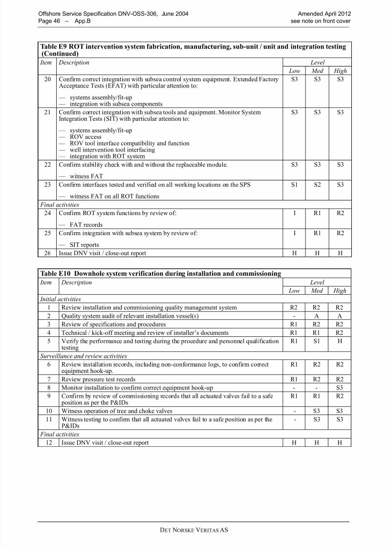
8/10/2019 oss-306_2012-04
http://slidepdf.com/reader/full/oss-3062012-04 46/58DET NORSKE VERITAS AS
Offshore Service Specification DNV-OSS-306, June 2004 Amended April 2012
Page 46 – App.B see note on front cover
20 Confirm correct integration with subsea control system equipment. Extended FactoryAcceptance Tests (EFAT) with particular attention to:
— systems assembly/fit-up — integration with subsea components
S3 S3 S3
21 Confirm correct integration with subsea tools and equipment. Monitor SystemIntegration Tests (SIT) with particular attention to:
— systems assembly/fit-up — ROV access — ROV tool interface compatibility and function — well intervention tool interfacing — integration with ROT system
S3 S3 S3
22 Confirm stability check with and without the replaceable module.
— witness FAT
S3 S3 S3
23 Confirm interfaces tested and verified on all working locations on the SPS
— witness FAT on all ROT functions
S1 S2 S3
Final activities
24 Confirm ROT system functions by review of:
— FAT records
I R1 R2
25 Confirm integration with subsea system by review of:
— SIT reports
I R1 R2
26 Issue DNV visit / close-out report H H H
Table E10 Downhole system verification during installation and commissioning
Item Description Level
Low Med High
Initial activities
1 Review installation and commissioning quality management system R2 R2 R2
2 Quality system audit of relevant installation vessel(s) - A A
3 Review of specifications and procedures R1 R2 R2
4 Technical / kick-off meeting and review of installer’s documents R1 R1 R2
5 Verify the performance and testing during the procedure and personnel qualificationtesting
R1 S1 H
Surveillance and review activities
6 Review installation records, including non-conformance logs, to confirm correctequipment hook-up.
R1 R2 R2
7 Review pressure test records R1 R2 R2
8 Monitor installation to confirm correct equipment hook-up - - S3
9 Confirm by review of commissioning records that all actuated valves fail to a safe position as per the P&IDs
R1 R1 R2
10 Witness operation of tree and choke valves - S3 S3
11 Witness testing to confirm that all actuated valves fail to a safe position as per theP&IDs
- S3 S3
Final activities
12 Issue DNV visit / close-out report H H H
Table E9 ROT intervention system fabrication, manufacturing, sub-unit / unit and integration testing (Continued)
Item Description Level
Low Med High
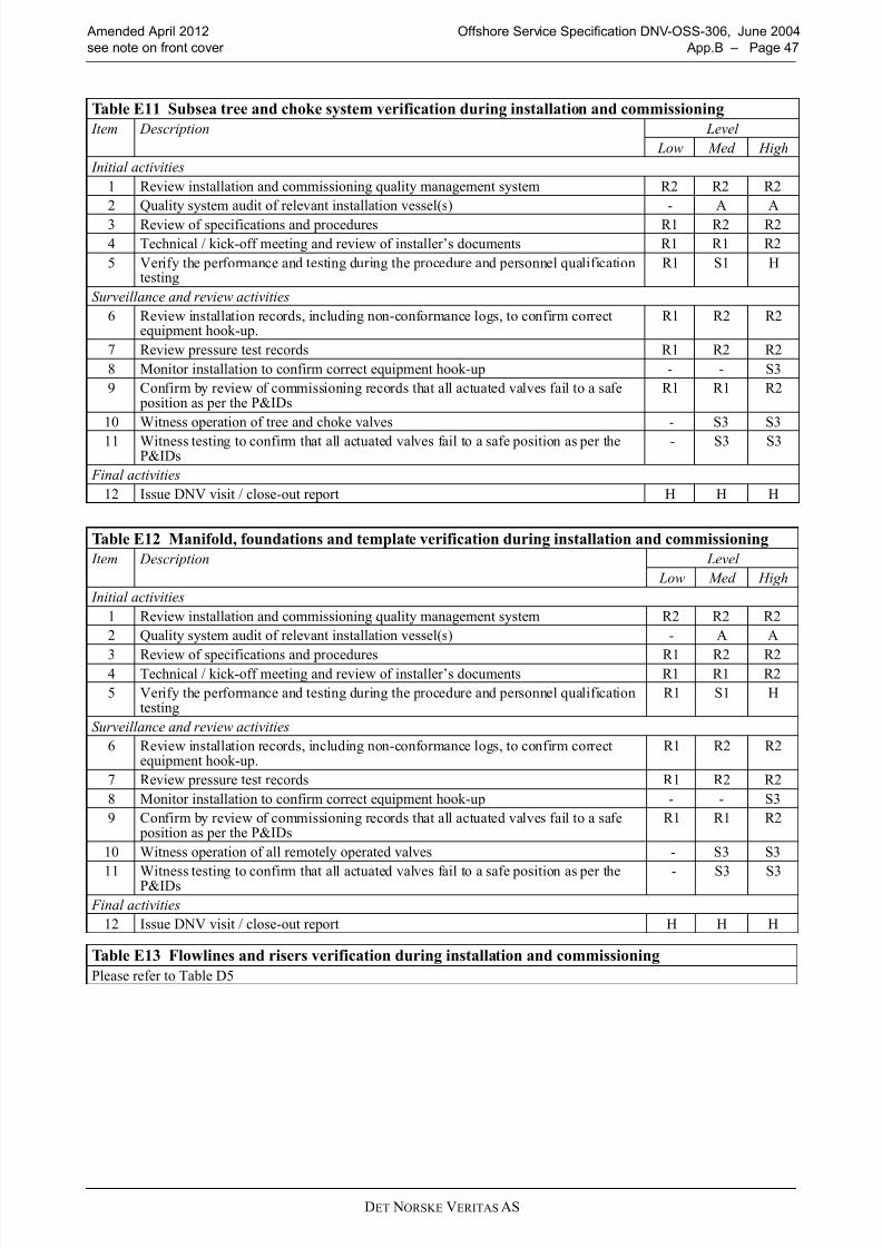
8/10/2019 oss-306_2012-04
http://slidepdf.com/reader/full/oss-3062012-04 47/58DET NORSKE VERITAS AS
Amended April 2012 Offshore Service Specification DNV-OSS-306, June 2004
see note on front cover App.B – Page 47
Table E11 Subsea tree and choke system verification during installation and commissioning
Item Description Level
Low Med High
Initial activities
1 Review installation and commissioning quality management system R2 R2 R2
2 Quality system audit of relevant installation vessel(s) - A A
3 Review of specifications and procedures R1 R2 R2
4 Technical / kick-off meeting and review of installer’s documents R1 R1 R2
5 Verify the performance and testing during the procedure and personnel qualificationtesting
R1 S1 H
Surveillance and review activities
6 Review installation records, including non-conformance logs, to confirm correctequipment hook-up.
R1 R2 R2
7 Review pressure test records R1 R2 R2
8 Monitor installation to confirm correct equipment hook-up - - S3
9 Confirm by review of commissioning records that all actuated valves fail to a safe position as per the P&IDs
R1 R1 R2
10 Witness operation of tree and choke valves - S3 S3
11 Witness testing to confirm that all actuated valves fail to a safe position as per theP&IDs
- S3 S3
Final activities
12 Issue DNV visit / close-out report H H H
Table E12 Manifold, foundations and template verification during installation and commissioning
Item Description Level
Low Med High
Initial activities
1 Review installation and commissioning quality management system R2 R2 R2
2 Quality system audit of relevant installation vessel(s) - A A
3 Review of specifications and procedures R1 R2 R24 Technical / kick-off meeting and review of installer’s documents R1 R1 R2
5 Verify the performance and testing during the procedure and personnel qualificationtesting
R1 S1 H
Surveillance and review activities
6 Review installation records, including non-conformance logs, to confirm correctequipment hook-up.
R1 R2 R2
7 Review pressure test records R1 R2 R2
8 Monitor installation to confirm correct equipment hook-up - - S3
9 Confirm by review of commissioning records that all actuated valves fail to a safe position as per the P&IDs
R1 R1 R2
10 Witness operation of all remotely operated valves - S3 S3
11 Witness testing to confirm that all actuated valves fail to a safe position as per theP&IDs - S3 S3
Final activities
12 Issue DNV visit / close-out report H H H
Table E13 Flowlines and risers verification during installation and commissioning
Please refer to Table D5
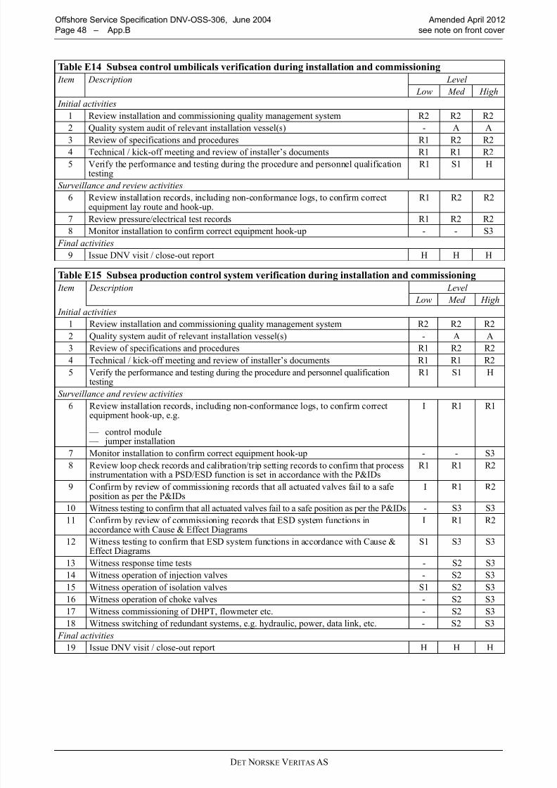
8/10/2019 oss-306_2012-04
http://slidepdf.com/reader/full/oss-3062012-04 48/58DET NORSKE VERITAS AS
Offshore Service Specification DNV-OSS-306, June 2004 Amended April 2012
Page 48 – App.B see note on front cover
Table E14 Subsea control umbilicals verification during installation and commissioning
Item Description Level
Low Med High
Initial activities
1 Review installation and commissioning quality management system R2 R2 R2
2 Quality system audit of relevant installation vessel(s) - A A
3 Review of specifications and procedures R1 R2 R24 Technical / kick-off meeting and review of installer’s documents R1 R1 R2
5 Verify the performance and testing during the procedure and personnel qualificationtesting
R1 S1 H
Surveillance and review activities
6 Review installation records, including non-conformance logs, to confirm correctequipment lay route and hook-up.
R1 R2 R2
7 Review pressure/electrical test records R1 R2 R2
8 Monitor installation to confirm correct equipment hook-up - - S3
Final activities
9 Issue DNV visit / close-out report H H H
Table E15 Subsea production control system verification during installation and commissioning Item Description Level
Low Med High
Initial activities
1 Review installation and commissioning quality management system R2 R2 R2
2 Quality system audit of relevant installation vessel(s) - A A
3 Review of specifications and procedures R1 R2 R2
4 Technical / kick-off meeting and review of installer’s documents R1 R1 R2
5 Verify the performance and testing during the procedure and personnel qualificationtesting
R1 S1 H
Surveillance and review activities
6 Review installation records, including non-conformance logs, to confirm correct
equipment hook-up, e.g.
— control module — jumper installation
I R1 R1
7 Monitor installation to confirm correct equipment hook-up - - S3
8 Review loop check records and calibration/trip setting records to confirm that processinstrumentation with a PSD/ESD function is set in accordance with the P&IDs
R1 R1 R2
9 Confirm by review of commissioning records that all actuated valves fail to a safe position as per the P&IDs
I R1 R2
10 Witness testing to confirm that all actuated valves fail to a safe position as per the P&IDs - S3 S3
11 Confirm by review of commissioning records that ESD system functions inaccordance with Cause & Effect Diagrams
I R1 R2
12 Witness testing to confirm that ESD system functions in accordance with Cause &
Effect Diagrams
S1 S3 S3
13 Witness response time tests - S2 S3
14 Witness operation of injection valves - S2 S3
15 Witness operation of isolation valves S1 S2 S3
16 Witness operation of choke valves - S2 S3
17 Witness commissioning of DHPT, flowmeter etc. - S2 S3
18 Witness switching of redundant systems, e.g. hydraulic, power, data link, etc. - S2 S3
Final activities
19 Issue DNV visit / close-out report H H H

8/10/2019 oss-306_2012-04
http://slidepdf.com/reader/full/oss-3062012-04 49/58DET NORSKE VERITAS AS
Amended April 2012 Offshore Service Specification DNV-OSS-306, June 2004
see note on front cover App.B – Page 49
Table E16 Subsea processing system verification during installation and commissioning
Item Description Level
Low Med High
Initial activities
1 Review installation and commissioning quality management system R2 R2 R2
2 Quality system audit of relevant installation vessel(s) - A A3 Review of specifications and procedures R1 R2 R2
4 Technical / kick-off meeting and review of installer’s documents R1 R1 R2
5 Verify the performance and testing during the procedure and personnel qualificationtesting
R1 S1 H
Surveillance and review activities
6 Review installation records, including non-conformance logs, to confirm correctequipment hook-up.
R1 R2 R2
7 Review pressure test records R1 R2 R2
8 Monitor installation to confirm correct equipment hook-up - - S3
9 Confirm by review of commissioning records that all actuated valves fail to a safe position as per the P&IDs
R1 R1 R2
10 Witness operation of subsea separation system, confirmation separation is withinspecification S1 S2 S3
11 Witness operation of subsea boosting system, confirmation boosting is withinspecification
S1 S2 S3
12 Witness operation of all remotely operated valves S1 S2 S3
13 Witness testing to confirm that all actuated valves fail to a safe position as per the P&IDs S1 S2 S3
Final activities
14 Issue DNV visit / close-out report H H H

8/10/2019 oss-306_2012-04
http://slidepdf.com/reader/full/oss-3062012-04 50/58
8/10/2019 oss-306_2012-04
http://slidepdf.com/reader/full/oss-3062012-04 51/58DET NORSKE VERITAS AS
Amended April 2012 Offshore Service Specification DNV-OSS-306, June 2004
see note on front cover App.C – Page 51
502 Audit reports shall contain information such as whether:
— the company has a documented quality system. — this quality system been certified by an accredited Certification Body for the product (or service) in
question. — the quality system covers the following quality assurance elements adequately for the product:
— organisation, — authority/responsibility, — job descriptions for key persons, — internal quality audits, — documentation change control, — job instructions/procedures, — non-conformance/corrective action,
— there are adequate procedures for activities such as:
— calibration of equipment, — material identification and marking, — control of special processes such as welding, NDT, PWHT, — non-conformance identification and handling,
— inspection status, — final inspection,
— the company’s facilities are, in general, considered adequate for the scope of supply, — a quality plan been prepared for the order concerned, — the purchaser or their appointed inspection agency are planned to attend the works, — there are any problem areas identified.
503 An example of a typical audit report is shown at the end of the document.
A 600 Visit reports
601 Visit reports are documentation/recording of attendance activity by DNV.
Guidance note:
Visit reports are and may be called by different names. Examples are Inspection Release Note, Survey Report,
Inspection Certificate, Site Report, etc.
---e-n-d---of---G-u-i-d-a-n-c-e---n-o-t-e---
602 A visit report shall contain enough information to identify clearly the product or service that has beenexamined, the operating conditions or specifications to which it has been examined and the conclusion reached
by DNV.
603 The visit report shall be printed on the relevant form and shall contain as much information as possiblein accordance with the standard headings in the form. In addition, the report number shall be shown.
604 An example of a typical Visit Report is shown at the end of the document.
B. Use of Quality Management Systems
B 100 General
101 The assurance of subsea facility integrity and function requires that gross errors during design,construction and operation be minimised. The likelihood of gross errors shall be reduced in a systematicmanner by the operation of a quality management system adequate for the work being carried out.
102 Quality management systems frequently are documented at three levels:
— the quality manual and related procedures document how the organisation, as a whole, manages the qualityof all its products and services,
— the quality plan documents the specific procedures related to a particular project, — the inspection and test plan documents how the quality control activities for a particular project shall be
carried out and recorded.
B 200 Quality plans201 The basic function of a quality plan is as a memory aid in the management of a project. In an organisationwith many quality procedures for a variety of functions the quality plan states those that are applicable to that
particular project. The quality plan acts as a route map through the complexities of management of the projectand highlights those activities relevant to quality management.
8/10/2019 oss-306_2012-04
http://slidepdf.com/reader/full/oss-3062012-04 52/58DET NORSKE VERITAS AS
Offshore Service Specification DNV-OSS-306, June 2004 Amended April 2012
Page 52 – App.C see note on front cover
202 The project quality plan normally consists of two parts; firstly, a narrative description of the means of controlling the project, and secondly, a tabular description of the inspections and tests to be carried out duringthe work.
203 The quality plan should address:
— organisational details of the project, — authorities and responsibilities of key personnel,
— interfaces between, the client, contractors, sub-contractors and third parties, — quality assurance activities placed on sub-contractors, — cross references to existing company procedures.
204 The narrative part of the quality plan should include a description of:
— the applicable standards, — project organisation and responsibilities, — review of the contractual requirements, — project planning and progress reporting, — procedures for such activities as design control, purchasing, construction, installation, commissioning,
interface control and auditing , — procedures for inspection and maintenance as well as normal operation — emergency response issues.
205 Additionally, the narrative part of the plan should describe the documentation requirements. It should bespecified:
— what documents are required,
— at what stage these documents are required, — who is responsible for preparing the documents, — relevant parties to whom documents are submitted, — how any necessary approvals are acquired, — who has originals and who has copies, — if copies have to be certified copies,
— the length of time documents are to be retained and by whom.
B 300 Inspection and test plans
301 The tabular description of the inspections and tests to be carried out during the work is frequently knownas the inspection and test plan.
302 The following items should be checked for inclusion within the inspection and test plan:
— each inspection and test point and its relative location in the production cycle should be shown, — the characteristics to be inspected and tested at each point should be identified, — the use of sub-contractors should be indicated and details of how the verification of sub-contractor’s quality
shall be carried out should be shown,
— hold points established by the constructor, the operator or a third party, where witness or review of theselected inspection or test is required, should be shown.
B 400 Review of quality management programme
401 The contractor’s quality manual shall be reviewed for compliance with ISO 9001 or 9002 as appropriate.The contractor’s operations should be audited to establish compliance with the documented system.
402 If the contractor has a quality system certified by an accredited third party certification body, this may be taken as evidence of a satisfactory quality system provided the certificate is relevant to the contractor’s scopeof work for the project. However, the last two years’ periodical audit reports shall be reviewed to identify if any recurring non-conformities have been revealed.
403 Any weaknesses revealed during this audit, or review of periodical audit reports, shall be consideredwhen planning the contractor monitoring activities.
404 Surveillance of the continuing acceptability of the contractor’s quality management system is carried out
by observing a selection of audits carried out by the contractor as part of its internal audit system. The auditsto be observed should be selected over the length of the project at suitable intervals and should cover as widea selection of activities as possible.
405 Contractors’ inspection and test plans for the various activities undertaken during their scope of work for the pipeline shall be reviewed and accepted, if adequate.

8/10/2019 oss-306_2012-04
http://slidepdf.com/reader/full/oss-3062012-04 53/58DET NORSKE VERITAS AS
Amended April 2012 Offshore Service Specification DNV-OSS-306, June 2004
see note on front cover App.C – Page 53
C. Document forms
C 100 Introduction
101 The end of this appendix includes example forms for use by DNV in verification.
102 The following forms are included:
— Statement of Compliance
— Verification Comments Sheet — Audit Report — Visit Report
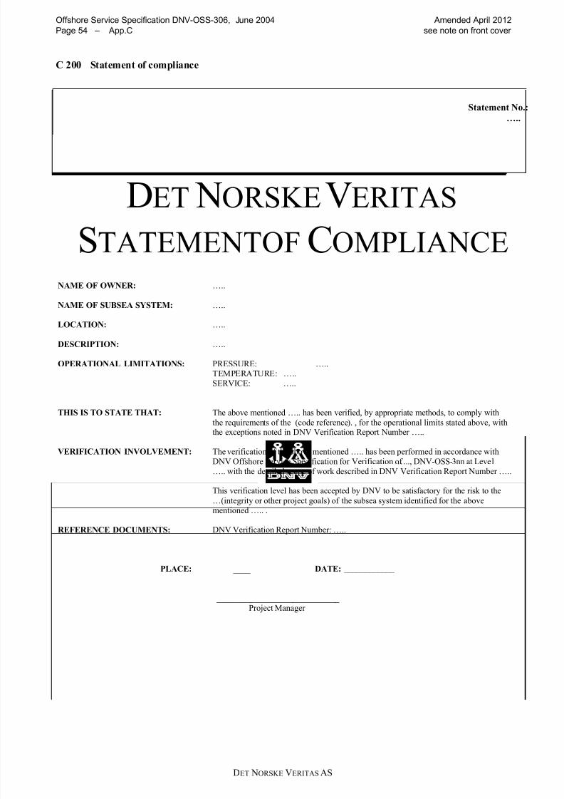
8/10/2019 oss-306_2012-04
http://slidepdf.com/reader/full/oss-3062012-04 54/58DET NORSKE VERITAS AS
Offshore Service Specification DNV-OSS-306, June 2004 Amended April 2012
Page 54 – App.C see note on front cover
C 200 Statement of compliance
Statement No.:
…..
DET NORSKEVERITAS
STATEMENTOF COMPLIANCE
NAME OF OWNER: …..
NAME OF SUBSEA SYSTEM: …..
LOCATION: …..
DESCRIPTION: …..
OPERATIONAL LIMITATIONS: PRESSURE: …..TEMPERATURE: …..
SERVICE: …..
THIS IS TO STATE THAT: The above mentioned ….. has been verified, by appropriate methods, to comply with
the requirements of the (code reference). , for the operational limits stated above, withthe exceptions noted in DNV Verification Report Number …..
VERIFICATION INVOLVEMENT: The verification of the above mentioned ….. has been performed in accordance with
DNV Offshore Service Specification for Verification of ….., DNV-OSS-3nn at Level
….. with the detailed scope of work described in DNV Verification Report Number …..
This verification level has been accepted by DNV to be satisfactory for the risk to the
…(integrity or other project goals) of the subsea system identified for the abovementioned ….. .
REFERENCE DOCUMENTS: DNV Verification Report Number: …..
PLACE: ______________ DATE: ____________
_____________________________ Project Manager
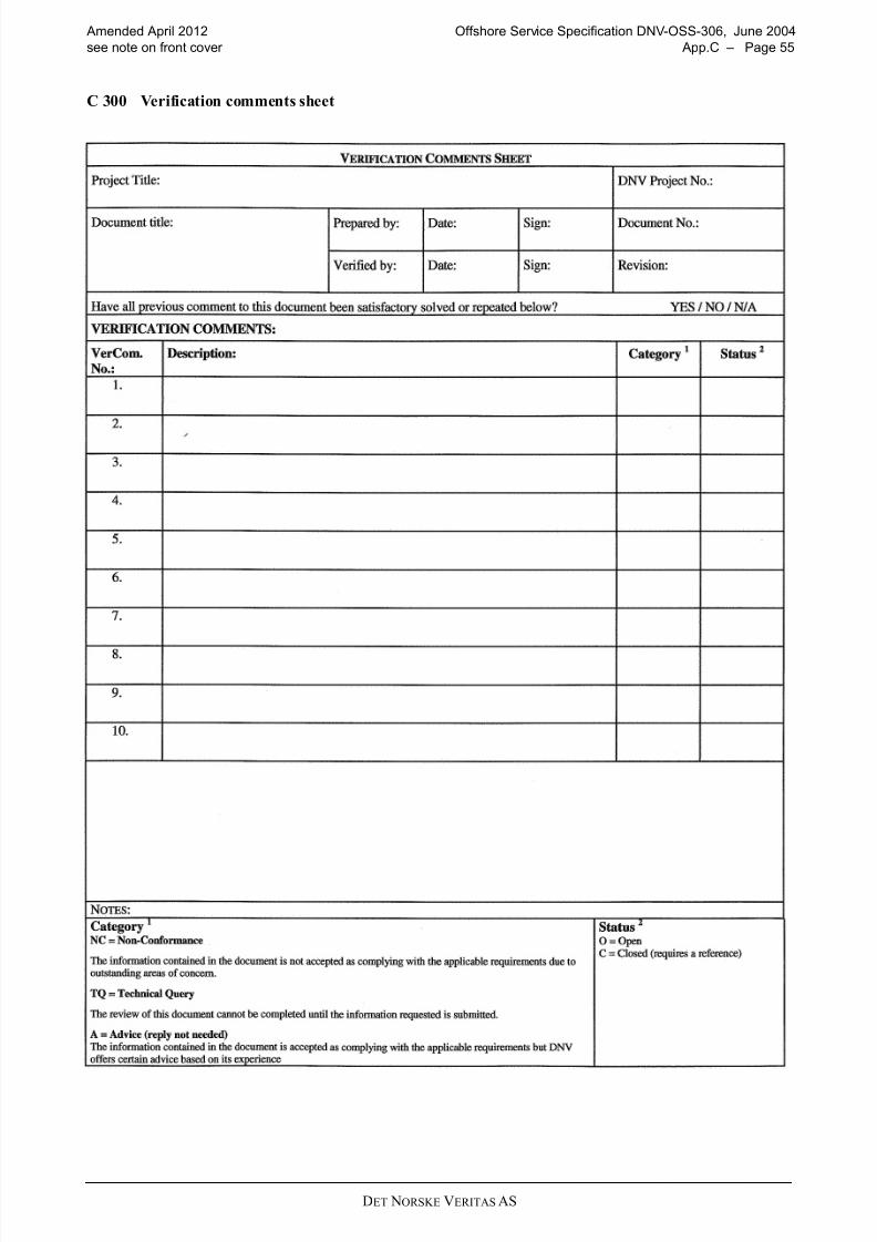
8/10/2019 oss-306_2012-04
http://slidepdf.com/reader/full/oss-3062012-04 55/58DET NORSKE VERITAS AS
Amended April 2012 Offshore Service Specification DNV-OSS-306, June 2004
see note on front cover App.C – Page 55
C 300 Verification comments sheet

8/10/2019 oss-306_2012-04
http://slidepdf.com/reader/full/oss-3062012-04 56/58

8/10/2019 oss-306_2012-04
http://slidepdf.com/reader/full/oss-3062012-04 57/58DET NORSKE VERITAS AS
Amended April 2012 Offshore Service Specification DNV-OSS-306, June 2004
see note on front cover App.C – Page 57
Audit report page 2

8/10/2019 oss-306_2012-04
http://slidepdf.com/reader/full/oss-3062012-04 58/58
Offshore Service Specification DNV-OSS-306, June 2004 Amended April 2012
Page 58 – App.C see note on front cover
C 500 Visit report