OPERATION MANUAL iPex - NSK Tech Service & … EU directive 93/42/EEC was applied in the design and...
14
Digital Apex Locator iPex OPERATION MANUAL 0197 OM-E0285E
Transcript of OPERATION MANUAL iPex - NSK Tech Service & … EU directive 93/42/EEC was applied in the design and...
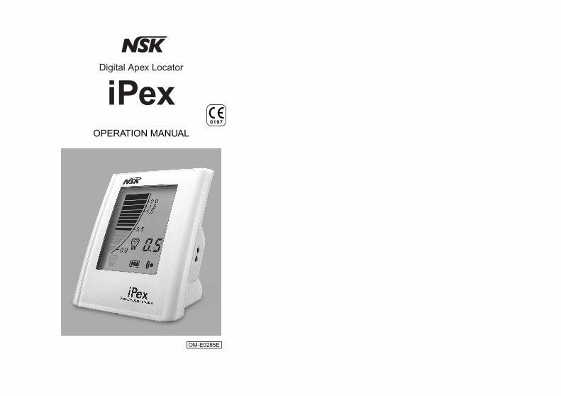
Digital Apex Locator
iPexOPERATION MANUAL
0197
OM-E0285E

The EU directive 93/42/EEC was applied in the design and production of this medical device.
Thank you for purchasing the iPex. This is apex locator. Read this Operation Manual carefully before use for operation instructions, care and maintenance. Keep this Operation Manual for future reference.
n Classifications of equipment • Type of protection against electric shock :
- Internally powered equipment • Degree of protection against electric shock :
- Type B applied part • Method of sterilization or disinfection recommended by the
manufacture :- See 7.(2) Sterilization
• Degree of protection against ingress of water as detailed in the current edition of IEC 60529 :- Unit…IPX1 (Protected against vertically falling water drops)
• Degree of safety of application in the presence of a flammable anesthetic mixture with air or with oxygen or nitrous oxide :- EQUIPMENT not suitable for use in the presence of a
flammable anesthetic mixture with air or with oxygen or nitrous oxide.
• Mode of operation :- Continuous operation

CONTENTS
Cautions for handling and operation …………………… 2
1. Features …………………………………………………… 5
2. Specifications ……………………………………………… 6
3. Component Names ………………………………………… 6
4. Installation and Assembly ………………………………… 10
5. Operating Procedures …………………………………… 12
6. Alarm Sound Volume Control …………………………… 15
7. Cleaning / Sterilization …………………………………… 16
8. Changing Batteries ………………………………………… 17
9. Troubleshooting …………………………………………… 20
10. Warranty …………………………………………………… 22
11. Disposing Product ………………………………………… 22
Cautions for handling and operationn Read these cautions carefully and use only as intended or
instructed.n Safety instructions are intended to avoid potential hazards
that could result in personal injury or damage to the device. Safety instructions are classified as follows in accordance with the seriousness of the risk.
1 2
DANGER
WARNING
CAUTION
NOTICE
Explains an instruction where death or serious injury may occur.A hazard that could result in bodily injury or damage to the device if the safety instructions are not followed.A hazard that could result in light or moderate bodily injury or damage to the device if the safety instructions are not followed.General information needed to operate the device safely.
Class Degree of Risk
DANGER • This product is powered by batteries only. Never use
batteries other than batteries designated in this manual. • Be sure to replace four batteries of the same type from the
same manufacturer at the same time for use. Fluid leakage or rupture may occur by mixing and using different types of batteries or use of mixed old and new batteries or consumed and fully charged batteries.
• Manganese dry batteries and alkali dry batteries cannot be charged. Never charge them. Fluid leakage or rupture may occur.
• Do not disassemble or alter the device.

WARNING
CAUTION
• This product is not built as waterproof. Do not spill water or a chemical solution onto or into the unit. Failure to do so may result in fire or electric shock due to a short-circuit or rusting.
• If you should notice battery fluid leak within the unit, deformation of the unit casing or partial discoloring, immediately stop use and contact your dealer.
• Should the leaking battery fluid get into your eyes, immediately wash eyes thoroughly with clean water and see your doctor. Failure to do so may result in loss of sight.
• Should the battery fluid leak and adhere to skin or clothing, immediately wash the exposed skin thoroughly with clean water and completely wash away the fluid. Failure to do so may result in skin complications.
• If you will not use the product for a long period of time, remove the batteries from the unit to avoid fluid leak.
• Exercise sufficient care in using the product by giving patient safety first priority.
• The product is to be used only for dental treatment by qualified personnel.
• Buy commercially available batteries designated in this Manual. Thoroughly read each battery manufacturer’s manual before using the respective batteries.
• Do not use or leave the product in a high-temperature environment such as under strong direct sunlight, in a car under a blazing sun, by a fire, or near a stove.
• Make sure if the product works properly by using "Tester" attached, prior to use.
• Do not allow any impact on the unit. Do not drop the unit. • Pay attention to the direction of batteries when setting.
Forcible setting in the wrong direction may cause damage and fluid leakage due to a short circuit.
3 4
NOTICE
• Do not allow conductive materials such as wires, safety pins, etc., to enter into the battery case.
• If chemical, solvent or antiseptic solution is deposited on this product, immediately wipe it away. Discoloration or deformation may occur if left as it is.
• The system functions normally in the environment where the temperature is at 0-40°C, humidity at 10-85% RH, atmospheric pressure at 500-1060hPa, and no moisture condensation in the Control Unit. Use at outside of these limits may cause malfunction.
• The unit consumes electricity very slightly even when the power supply is off. If you will not use the product for a long period of time, remove the batteries from the unit.
• If the battery mark flashes, replace with a new battery as soon as possible. If consumed batteries are kept in this product as they are, fluid leakage may occur. In particular, pay attention to the manganese dry batteries from which fluid is easily leaked due to its structure as it gets older.
• This product has been designed on the assumption that manganese dry batteries or alkali dry batteries are used. Charging type batteries such as nickel-cadmium batteries and nickel metal hydride batteries of the same shape can also be used, however, are limited by the following.™This product does not have charging function.™Even if nickel-cadmium batteries and nickel metal hydride
batteries are fully charged, they have lower voltage than manganese batteries or alkali dry batteries, therefore, the battery remaining mark indicates slightly less. This is due to a difference in battery voltage, and not a failure.
5 6
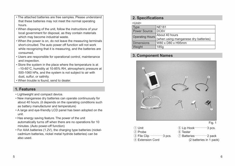
q Unitw Probee File Clip …………3 pcs.r Extension Cord
t Lip Hook…………3 pcs.y Testeru Batteries…………2 pack
(2 batteries in 1 pack)
3. Component Names
<Unit>
2. Specifications
Fig. 1
TypePower Source
Operating Hours
DimensionsWeight
NE181DC6VAbout 40 hours(when using manganese dry batteries)W80 x D80 x H95mm185g
• Lightweight and compact device. • New manganese dry batteries can operate continuously for
about 40 hours. (it depends on the operating conditions such as battery manufacturer and temperature)
• A large and eye-friendly LCD panel has been adopted on the unit.
• Has energy saving feature. The power of the unit automatically turns off when there are no operations for 10 minutes. (Auto power-off function)
• For AAA batteries (1.2V), the charging type batteries (nickel-cadmium batteries, nickel metal hydride batteries) can be also used.
1. Features
• The attached batteries are free samples. Please understand that these batteries may not meet the normal operating hours.
• When disposing of the unit, follow the instructions of your local government for disposal, as they contain materials which may become industrial waste.
• When the power is on, do not leave the measuring terminals short-circuited. The auto power off function will not work while recognizing that it is measuring, and the batteries are consumed.
• Users are responsible for operational control, maintenance and inspection.
• Store the system in the place where the temperature is at –10-60°C, humidity at 10-85% RH, atmospheric pressure at 500-1060 hPa, and the system is not subject to air with dust, sulfur, or salinity.
• When trouble is found, send to dealer.
q
w
e r
t y u

[Operation Key and LCD Panel.
¡POWER Key • When this is pressed for about one second or longer, the
alarm sounds and the power is turned ON, and then the liquid crystal display lights up.
• When this is pressed for about one second or longer with the power being ON, the alarm sounds and the power is turned OFF, and then the liquid crystal display lights off.
Fig. 2
¡Bar GraphLCDDisplays the present position of the top of the file.
¡Target Value BarLCDDisplays the target value while flashing.
¡Number DisplayLCDDisplays the present position of the top of the file by number.
¡Dental MarkLCD
This is displayed while the present position of the top of the file is “0.5 to 0.0.”
This flashes to warn when the present position of the top of the file exceeds “0.0.”
¡Alarm Key • The alarm sound volume can be adjusted. (See 6. Alarm
Sound Volume Control)LCDThe present alarm mark is displayed.
Big sound volume
Middle sound volume
7 8
<LCD Panel>
POWER Key
Alarm Key
Bar Graph
Dental Mark Alarm Mark
Battery Mark
NumberDisplay
TargetValueBar
[This indicates that all displays are lighted.
9 10
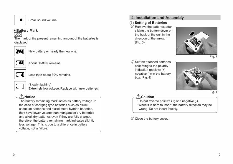
4. Installation and Assembly
• Do not reverse positive (+) and negative (-). • When it is hard to insert, the battery direction may be
wrong. Do not insert forcibly.
Caution
Fig. 3
Fig. 4
Small sound volume
¡Battery MarkLCDThe mark of the present remaining amount of the batteries is displayed.
New battery or nearly the new one.
About 30-80% remains.
Less than about 30% remains.
(Slowly flashing)Extremely low voltage. Replace with new batteries.
The battery remaining mark indicates battery voltage. In the case of charging type batteries such as nickel-cadmium batteries and nickel metal hydride batteries, they have lower voltage than manganese dry batteries and alkali dry batteries even if they are fully charged, therefore, the battery remaining mark indicates slightly less voltage. This is due to a difference in battery voltage, not a failure.
Notice
(1) Setting of BatteriesRemove the batteries after sliding the battery cover on the back of the unit in the direction of the arrow. (Fig. 3)
Set the attached batteries according to the polarity indication (positive (+), negative (-)) in the battery box. (Fig. 4)
Close the battery cover.
1
2
3

(2) Probe ConnectionInsert the probe into the probe connector at the side of the unit. (Fig.5)
Fig. 5
(3) File Clip ConnectionConnect the plug of the file clip to the plug of either probe. (Fig. 6)
Fig. 6
(4) Lip Hook ConnectionConnect the lip hook to the plug of the other probe. (Fig. 7)
Fig. 7
11 12
(5) Extension Cord ConnectionUse this for extension between the file clip or lip hook and probe if necessary. (Fig. 8)
Fig. 8
Fig. 9
Fig. 10
Extension Cord
5. Operating Procedures(1) Inspection before useBe sure to carry out an operation check with a tester before use to confirm that it operates properly.
Press the power key for about one second or longer to turn ON power. (Liquid crystal display lights up)Pinch either one of the electrodes on the tester with a file clip. (Fig. 9)
Expose a lip hook to the other electrode on the tester. (Fig. 10)
1
2
3
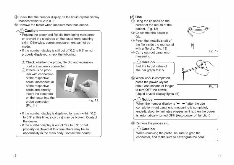
(2) UseHang the lip hook on the corner of the mouth of the patient. (Fig. 12)
13 14
When removing the probe, be sure to grab the connector, and make sure to never grab the cord.
Caution
Set the target value of the bar graph to 0.5.
Caution
When the number display is “ ” after the use completion (root canal end-measuring is completely ended), about ten minutes elapses as it is, then the power is automatically turned OFF. (Auto-power off function)
Notice
Fig. 12
Check that the power is ON.Pinch the metallic shaft of the file inside the root canal with a file clip. (Fig. 13)Carry out root canal end-measuring.
When work is completed, press the power key for about one second or longer to turn OFF the power. (Liquid crystal display lights off)
Remove the probes etc.
Fig. 13
Check that the number display on the liquid crystal display reaches within “0.2 to 0.9.”Remove the tester when measurement has ended.
Fig. 11
• Prevent the tester and file clip from being moistened or prevent the electrode on the tester from touching skin. Otherwise, correct measurement cannot be made.
• If the number display is still out of “0.2 to 0.9” or not properly displayed, check the following.
Check whether the probe, file clip and extension cord are securely connected.If there is no prob-lem with connection of the respective cords, disconnect all of the respective cords and directly insert the electrode on the tester into the probe connector. (Fig.11)
• If the number display is displayed to reach within “0.2 to 0.9” at this time, a cord (s) may be broken. Contact the dealer.
• If the number display is out of “0.2 to 0.9” or not properly displayed at this time, there may be an abnormality in the main body. Contact the dealer.
Caution
4
5
1
2
6
5
4
3
2
1

The alarm sound volume can be controlled at the three steps of “Big Volume, Middle Volume and Small Volume.”
Lightly push the alarm key with the thin bar. (Fig. 14)The alarm mark on the LCD panel changes, and the sound volume changes.The sound volume is adjusted each time the alarm key is pressed.
• Do not push the alarm key strongly. Otherwise, it may be broken.
• Avoid using a hard bar such as metal for the thin bar. Otherwise, the alarm key may be damaged.
• Do not insert the thin bar into the speaker by mistakenly confusing it with the alarm key. Otherwise, the speaker may be damaged.
6. Alarm Sound Volume Control
Caution
The sound level is retained, even if the power is turned off.
Notice
Fig. 14
Speaker
15 16
(1) CleaningIf dirt sticks on the unit, probe, file clip, lip hook, or extension cord. Then, soak a clean cloth in water and squeeze cloth tightly to drain water. Use the cloth to wipe away dirt. After that, wipe off with an alcohol soaked clean cloth.
(2) Sterilization • Autoclave sterilization is recommended. • Sterilization required after each patient as noted below. • Can be autoclaved: file clip, lip hook, extension cord
n Autoclave ProcedureWipe away dirt on the surface of the file clip and lip clip with a clean cloth dipped in water and sufficiently squeezed. And then, wipe with a clean cloth dipped with disinfecting alcohol. (Refer to 7. (1) Cleaning)Insert into an autoclave pouch. Seal the pouch.Autoclavable up to a max. 135˚C. Ex) Autoclave for 20 min. at 121˚C or 15 min. at 132˚C.Keep the handpiece in the autoclave pouch to keep it clean until you use it.
7. Cleaning / Sterilization
To clean the product, do not use any solvent such as benzine and, thinner.
Caution
Do not autoclave any parts (the unit, and probe) other than those that can be subjected to autoclave sterilization.
Caution
1
2
3
1
23
4
17 18
• Be sure to turn OFF the power when changing batteries.
• Do not open any part other than the battery cover. • Use batteries designated by NSK. Unless designated
batteries are used, breakage, fluid leakage or rupture may occur.Designated batteries: AAA cell
Manganese dry batteries, Alkali dry batteries 1.5VNickel cadmium batteries, Nickel metal hydride batteries 1.2V* Use reliable manufactures’
batteries. • Be sure to replace four batteries of the same type
from the same manufacturer at the same time to use. Fluid leakage or rupture may occur by mixing and using different types of batteries or use of mixed old and new batteries or consumed and fully charged batteries.
• Do not work with wet hands. This may cause trouble due to short-circuiting of batteries and moisture infiltrating this product.
Caution on Changing Batteries • If the sterilizer has a dry process that exceeds 135°C,
skip the process. • Since the bottom shelf of the sterilizer is close to the
heat source, it can be too hot. Place instruments in the middle or top shelves.
• If autoclaved with other instruments stained with chemical solution, it could strip the plating and make the surface black.
• File clip, lip hook and extension cord are consumables. When they are discolored by repetition of autoclave sterilization, replace with new ones.
• If the battery remaining mark flashes slowly, immediately replace with new batteries.
• When replacing them by yourself, be sure to observe the following “ Caution on Changing Batteries” . Note that NSK shall not be held liable for any malfunction or failure resulting from your notfollowing the “ Caution on Changing Batteries”.
8. Changing Batteries
Caution
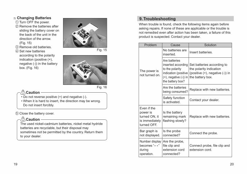
• Do not reverse positive (+) and negative (-). • When it is hard to insert, the direction may be wrong.
Do not insert forcibly.
Caution
The used nickel-cadmium batteries, nickel metal hydride batteries are recyclable, but their disposal may sometimes not be permitted by the country. Return them to your dealer.
Caution
Fig. 15
Fig. 16
19
When trouble is found, check the following items again before asking repairs. If none of these are applicable or the trouble is not remedied even after action has been taken, a failure of this product is suspected. Contact your dealer.
20
9. Troubleshooting
Insert batteries.
Set batteries according to the polarity indication (positive (+), negative (-)) in the battery box.
Replace with new batteries.
Contact your dealer.
Replace with new batteries.
Connect the probe.
Connect probe, file clip and extension cord.
No batteries are inserted.
Are batteries inserted according to the polarity indication (positive (+), negative (-)) in the battery box?
Are the batteries being consumed?
Safety function is activated.
Is the battery remaining mark flashing slowly?
Is the probe connected?
Are the probe, file clip and extension cord connected?
The power is not turned on.
Even if the power is turned ON, it is immediately turned OFF.
Bar graph is not displayed.
Number display becomes “ ” during operation.
Problem Cause Solution
n Changing BatteriesTurn OFF the power.Remove the batteries after sliding the battery cover on the back of the unit in the direction of the arrow.(Fig. 15)Remove old batteries.Set new batteries according to the polarity indication (positive (+), negative (-)) in the battery box. (Fig. 16)
1
2
3
4
Close the battery cover.5
21 22
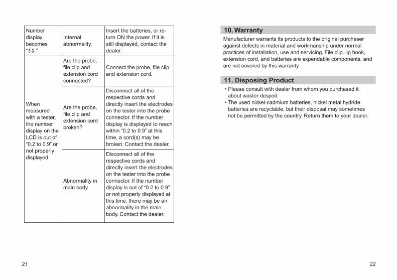
Manufacturer warrants its products to the original purchaser against defects in material and workmanship under normal practices of installation, use and servicing. File clip, lip hook, extension cord, and batteries are expendable components, and are not covered by this warranty.
10. Warranty
• Please consult with dealer from whom you purchased it about waster despoil.
• The used nickel-cadmium batteries, nickel metal hydride batteries are recyclable, but their disposal may sometimes not be permitted by the country. Return them to your dealer.
11. Disposing Product
Insert the batteries, or re-turn ON the power. If it is still displayed, contact the dealer.
Connect the probe, file clip and extension cord.
Disconnect all of the respective cords and directly insert the electrodes on the tester into the probe connector. If the number display is displayed to reach within “0.2 to 0.9” at this time, a cord(s) may be broken. Contact the dealer.
Disconnect all of the respective cords and directly insert the electrodes on the tester into the probe connector. If the number display is out of “0.2 to 0.9” or not properly displayed at this time, there may be an abnormality in the main body. Contact the dealer.
Internal abnormality.
Are the probe, file clip and extension cord connected?
Are the probe, file clip and extension cord broken?
Abnormality in main body.
Number display becomes “ .”
When measured with a tester, the number display on the LCD is out of “0.2 to 0.9” or not properly displayed.