
of RF - Digital Library/67531/metadc695244/m2/1/high...Mitsuru Uesakd, Atsushi Ogata**, Hiroshi...
6
Presented at: 1997 Japan Particle Accelerator Conference - Spring 8 Kyoto, Japan November 20-25,1997 BNL- 65003 CO.NF-47/) Ilk--- Development of High Duty Operation RF Photoinjector Fumio Sakai, Xjie Wang"", Hideyuki Kotaki, Kazuhisa Nakajima, Takahiro Watanabe', Keniti Kinoshita', Shuji Kondo, Masaki Kando, Hideki Dewa, Toru Ueda', Koji Yoshii', Mitsuru Uesakd, Atsushi Ogata**, Hiroshi Naanishi", Masakazu Washio"', Akira Endo"', Ilan Ben-Zvi"", John Skaritkd"', Martin Woodle"" Japan Atomic Energy Research Institute, Takai, Ibaraki, Japan 'Nuclear Engineering Research Laboratory, The University of Tokyo, Tokai, Ibaraki, *-K, Tsukuba, Ibaraki, Japan ""WSLS, Brookhaven National Laboratory, Upton, NY 11973-5000 Japan +++ Sumitomo Heavy Industries, Ltd., Tanashi, Tokyo, Japan November 1997 19980401 070 f c National Synchrotron Light Source Brookhaven National Laboratory Upton, NY 11973 Work performed under the auspices of the U. S. Department of Energy, under contract DE-AC02-76CH00016
Transcript of of RF - Digital Library/67531/metadc695244/m2/1/high...Mitsuru Uesakd, Atsushi Ogata**, Hiroshi...
Presented at: 1997 Japan Particle Accelerator Conference - Spring 8 Kyoto, Japan November 20-25,1997
BNL- 65003
C O . N F - 4 7 / ) I l k - - - Development of High Duty Operation RF Photoinjector
Fumio Sakai, Xjie Wang"", Hideyuki Kotaki, Kazuhisa Nakajima, Takahiro Watanabe', Keniti Kinoshita', Shuji Kondo, Masaki Kando, Hideki Dewa, Toru Ueda', Koji Yoshii',
Mitsuru Uesakd, Atsushi Ogata**, Hiroshi Naanishi", Masakazu Washio"', Akira Endo"', Ilan Ben-Zvi"", John Skaritkd"', Martin Woodle""
Japan Atomic Energy Research Institute, Takai, Ibaraki, Japan 'Nuclear Engineering Research Laboratory, The University of Tokyo, Tokai, Ibaraki,
*-K, Tsukuba, Ibaraki, Japan
""WSLS, Brookhaven National Laboratory, Upton, NY 1 1973-5000
Japan
+++ Sumitomo Heavy Industries, Ltd., Tanashi, Tokyo, Japan
November 1997
19980401 070
f c
National Synchrotron Light Source Brookhaven National Laboratory
Upton, NY 11973
Work performed under the auspices of the U. S. Department of Energy, under contract DE-AC02-76CH000 16

DISCLAIMER
This report was prepared as an account of work sponsored by an agency of the United States Government. Neither the United States Government nor any agency thereof, nor any of their employees, makes any warranty, express or implied, or assumes any legal liability or responsibility for the accuracy, completeness, or use- fulnas of any information, apparatus, product, or process disclosed, or represents that its use would not infringe privately owned rights. Reference herein to any spe- cific commercial product, process, or service by trade name, trademark, manufac- turer, or otherwise does not necessarily constitute or imply its endorsement, recom- mendation, or favoring by the United States Government or any agency thereof. The views and opinions of authors expressed herein do not necessarily state or reflect those of the United States Government or any agency thereof.
Development of High Duty Operation RF’ Photoinjector
Fumio SAKAI, ****Xijie WANG, Hideyuki KOTAKI, Kazuhisa NAKAJIMA,*TakahiroWATANABE, *Keniti KINOSHITA,Shuji KONDO, Masaki KAND0,Hideki DEWA , *Torn UEDA, *Koji YOSHII,
*Mitsum UESAKA,**Atsushi OGATA, **Hiroshi NAKANISHI,***Masakazu WASHIO, ***aim ENDO, ****Ilan BEN-ZVI, ****John SKARITKA, ****Martine WOODLE
Japan Atomic Energy Research Institute, Tokai, Ibaraki, Japan. *Nuclear Engineering Research Laboratory, The University of Tolqo, Tokai, Ibaraki, Japan
**KEK, Tsukuba, Ibaraki, Japan ***Sumitom0 Heavy Industries, Ltd., Tanashi, Tokyo, Japan
****Brookhaven National Laboratory, Upton, NY, U.S.A , Abstract
A W photoinjector for the high duty operation was designed and constructed by the BNUKEWSHI international collaboration and installed at the S-band linear accelerator of the University of Tokyo. Subpicosecond electron bunches compressed by a magnetic compression is planned to be used for the subpicosecond X-ray generation and the laser acceleration. Preliminary experiments of the RF photoinjector were performed. The measured value of the Cu cathode’s quantum efficiency was sx I Os.
1 Introduction
Technologies to obtain high brightness electron bunches with a low emittance and a short duration have been studied with photocathode RF guns using short pulse lasers in order to apply for new technologies, laser accelerator, FEL, X-ray generation by Compton scattering and so on’X2). More than ten years photocathode development and recent short pulse laser development, the photocathode is emerging as a standard laboratory tool for high brightness electron beam applications.
Laser wakefield accelerator (LWFA) expected as a compact high energy accelerator with high gradient particle acceleration has been studied. JAERI, KEK and the University of Tokyo have studied LWFA using a linac with a thermal electron gun, a magnetic Compressor, and a TW laser with IOOfk pulse length3). In order to get the low emittance and short bunched electron beam and also to accelerate higher efficiently, a RF photoinjector as a electron source was installed at this time.
RF photoinjector technologies has been integrated in Brookhaven National Laboratory(BNL)’). Recently, 1.6 cell RF photoinjector has been developed by the BNUSLACNCLA collaboration4). Based on this development, the improvement for high duty operation was performed by the BNLKEWSHI collaboration. Major improvements were water cooling channels removing RF heat and RF seal structure of a cathode plate. In the following section, the thermal analysis of the RF photocathode and the
other systems such as the solenoidal magnet, a laser and diagonostic system is reported. The results of preliminary experiments are also reproted.
2 RF photoinjector system
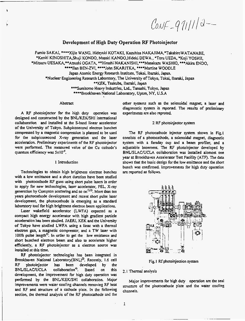
The RF photocathode injector system shown in Fig.1 consists of a photocathode, a solenoidal magnet, diagnostic system with a faraday cup and a beam profiler, and a adjustable basement. The RF photoinjector developed by BNUSLACNCLA collaboration was installed alomost one year at Brookhaven Accelerator Test Facility ( A T . The data shows that the basic design for the low emittance and the short bunch was confirmed. Improvements for high duty operation are reported as follows.
Fig. 1 Rf photoinjection system
2. I Thermal analysis
Major improvements for high duty operation are the seal structure of the photocathode plate and the water cooling channels.
.
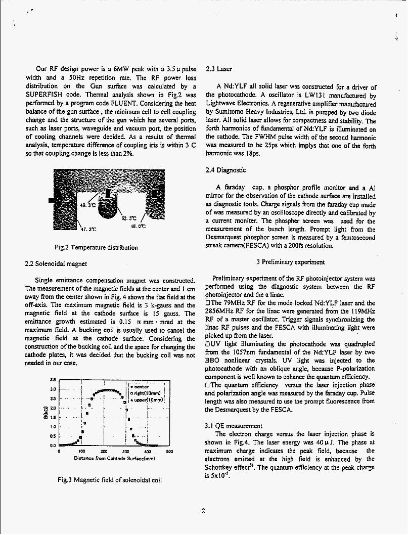
Our RF design power is a 6MW peak with 3 3.5 v pulse width and a 50Hz repetition rate. The RF power loss distribution on the Gun surface was calculated by a SUPERFISH code. Thermal analysis shown in Fig2 was performed by a program code FLUENT. Considering the heat balance of the gun surface , the minimum cell to cell coupling change and the structure ofthe gun which has several ports, such as laser ports, waveguide and vacuum PO& the position of cooling channels were decided. As a results of thermal analysis, temperature difference of coupling iris is within 3 C so that coupling change is less than 2%.
Fig.2 Temperature distribution
2.2 Solenoidal magnet
Single emittance compensation magnet was constructed. The measurement of the magnetic fields at the center and 1 cm away from the center shown in Fig. 4 shows the flat field at the off-axis. The maximum magnetic field is 3 k-gauss and the magnetic field at the cathode surface is 1.5 gauss. The emittance growth estimated is 0.15 n mm - mrad at the maximum field. A bucking coil is usually used to cancel the magnetic field at the cathode surface. Considering the construction of the bucking coil and the space for changing the cathode plates, it was decided that the bucking coil was not needed in our case.
_ _ 3.0
25 - 20 Y s m 1s
1 .o 05
0.0 0 loo 200 300 400 500
Distance from Cahtode Sudace(mm)
Fig3 Magnetic field o f solenoidal coil
2.3 Laser
A Nd:YLF all solid laser was constructed for a driver of the photocathode. A oscillator is LW13 I manufactured by Lightwave Electronics. A regenerative amplifier manufictured by Sumitomo Heavy Industries, Ltd. is pumped by two diode laser. All solid laser allows for compactness and stability. The forth hmonics of hndamental of Nd:YLF is illuminated on the cathode. The FWHM pulse width of the second harmonic was measured to be 25ps which implys that one of the forth harmonic was 18ps.
2.1 Diagnostic
A faraday cup, a phosphor profile monitor and a AI mirror for the observation of the cathode surface are installed as diagnostic tools. Charge signals From the faraday cup made of was measured by an oscilloscope directly and calibrated by a current moniter. The phospher screen was used for the measurement of the bunch length. Prompt light from the Desmarquest phosphor screen is measured by a femtosecond meak camera(FESCA) with a 200fs resolution.
3 Preliminary experiment
Preliminary experiment of the RF photoinjector system was performed using the diagnostic system between the RF photoinjector and the a linac. CThe 79MHz RF for the mode locked NdYLF laser and the 2856MHz RF for the linac were generated from the 1 I9MHz RF of a master oscillator. Trigger signals synchronizing the linac RF pulses and the FESCA with illuminating light were picked up h m the laser. CUV light illuminating the photocathode was quadrupled from the 1057nm hndamental of the NdYLF laser by two BBO nonlinear crystals. UV light was injected to the photocathode with an oblique angle, because P-polarization component is well known to enhance the quantum efficiency. r-iThe quantum efficiency versus the laser injection phase and polarization angle was measured by the M a y cup. Pulse length was also measured to use the prompt fluorescence from the Desmarquest by the FESCA.
.
3.1 QE measurement The electron charge versus the laser injection phase is
shown in Fig.4. The laser energy was 40 v J. The phase at maximurn charge indicates the peak field, because the electrons emitted at the high field is enhanced by the Schottkey effect?. The quantum efficiency at the peak charge is 5x I0-j.
2

0.5
0.4
0 5 0.3 ? : 0.2
0.1
0
CI
a
0
0 30 60 90 120 150 180 Laser Injection Phasddegree)
Fig.4 Electron charge emitted from the cathode versus laser injection phase
.
The electron charge emitted Trom the cathode is dependent on the polarization of the illumination light. The electron charge versus the polarization of light is shown in Fig5 The polarization of light was changed with a 1R A plate. It can be seen that available charge is maximized at a polarizer angle of 97 degree which corresponds to P-type polarized light on the cathode.
I I : I I I 0.4
60 90 1 20 150 180 Polarizer angle(degree)
Fig5 charge emitted from the cathode vs. Polarizer angle
3.3 Pulse lene@
, The pulse length measurement was performed by the FESCA using the prompt fluorescence from the Desmarquest phosphor screen. The bunch length Venus the laser injection phase is shown in Fig.6. The data of 100 shots accumulated and single shot are shown. I t can be seen that the jitter of system such as laser fluctuation is around lops. Due to the laser power limitation, this experiments was not performed with the electron charge constant, but the laser power constant The charactristics of the prompt fluorescence from the Desmarquest has not been recognized well, h0wever.h was confirmed that this method was a convinient tool in this bunch
region. The bunch length measurement in the subpicosecond region with the prompt fluorescence and the Cherenkov radiation will be performed after accelerating by the linac.
0 120
Fig.6 Electron bunch lens@ vs. laser injection phase
4. summary
The RF photocathode injector designed and constructed by the BNUKEWSHI collaboration was installed in the University of Tokyo. It was confirmed that the system of the RF photocathode injector was working. At next steps, electron emitted fkom the photoinjector is accelerated with the S-band linac, so more characteristics of the RF photoinjector such as the energy, the emittance, and the bunch length, will been studied.
Reference I]B.E.Carlsten et al, : Micro Bunches Workshop, Sep.28- 30( 1995) 21 X.J. Wang et al,: Nucl. Instr. And Meth. A356 (1995) 159 31M.Kando et al: PAC97,7V48 (1997) 4]D.T.Palmer, et al,: Proc. Part. Accel. Conf. , (1995) 982 5]T. Srinivasan-Rao et al: J.Appl.Phys.,77(3) (1995) I

M98003072 I1lll1111 Ill 111ll lllil11111111111111111111 IIIII 1111 1111
Report Number (14) -97 1 1 / 1 2 -_
'ubl. Date (11)
sponsor Code (18) f ibE ,E R J C Category (1 9)
DOE


![[ V ] r ( ) rf + Ñ × rf - GÑf t - fem.unicamp.brphoenics/SITE_PHOENICS/AULAS/ENERGY_EQ… · rf + Ñ × rf - GÑf = ... Novas variáveis podem ser introduzidas via VR ou diretamente](https://static.fdocument.pub/doc/165x107/5ba2a4ee09d3f2d14d8c57c4/-v-r-rf-n-rf-gnf-t-fem-phoenicssitephoenicsaulasenergyeq.jpg)

![Maker Faire Singapore by TAKASU Masakazu [Oversea Maker Faire Meetup 2016 Tokyo]](https://static.fdocument.pub/doc/165x107/58e971a61a28abd2148b57bb/maker-faire-singapore-by-takasu-masakazu-oversea-maker-faire-meetup-2016-tokyo.jpg)

