NZS 4297: Engineering design of earth · PDF fileNZS 4297:1998 Engineering Design of Earth...
63
NZS 4297 (1998): Engineering design of earth buildings [Building Code Compliance Documents B1 (VM1), B2 (AS1)]
Transcript of NZS 4297: Engineering design of earth · PDF fileNZS 4297:1998 Engineering Design of Earth...

Magna Carta—Tūtohinga Nui
We will sell to no man, we will not deny or defer to any man either justice or right.
Kore rawa e hoko ki te tangata, e kore e whakakāhoretia,
e tautuku rānei te tangata ki te ture, tika ranei.
NZS 4297 (1998): Engineering design of earthbuildings [Building Code Compliance Documents B1(VM1), B2 (AS1)]

NZS 4297:1998
Engineering Design ofEarth Buildings
NZS 4297:1998

Copy
right
Sta
ndar
ds N
ew Z
ealan
d *
COMMITTEE REPRESENTATIONThis Standard was prepared by the New Zealand-only sub-committee,BD/83/2, of the Joint Australia/New Zealand Technical CommitteeBD/83 Earth Buildings for the Standards Council established underthe Standards Act 1988. Sub-committee BD/6/2 consisted ofrepresentatives of the following organizations:
Hugh Morris Auckland UniversityMiles Allen Earth Building Association of New ZealandThijs Drupsteen Earth Building Association of New ZealandBob Gilkison Earth Building Association of New ZealandGraeme North Earth Building Association of New Zealand (Chair)Richard Walker Instituion of Professional Engineers New ZealandMin Hall New Zealand Instiute of ArchitectsJenny Christie Victoria University of Wellington
© COPYRIGHTThe copyright of this document is the property of the StandardsCouncil. No part of it may be reproduced by photocopying or by anyother means without the prior written permission of the Chief Executiveof Standards New Zealand unless the circumstances are covered byPart III of the Copyright Act 1994.
Standards New Zealand will vigorously defend the copyright in thisStandard. Every person who breaches Standards New Zealand'scopyright may be liable to a fine not exceeding $50,000 or to impris-onment for a term not to exceed three months. If there has been aflagrant breach of copyright, Standards New Zealand may also seekadditional damages from the infringing party, in addition to obtaininginjunctive relief and an account of profits.
Published by Standards New Zealand, the trading arm of theStandards Council, Private Bag 2439, Wellington 6020.Telephone: (04) 498 5990, Fax: (04) 498 5994.E-mail: [email protected]: www.standards.co.nz
AMENDMENTS
No Date of issue Description Entered by,and date
NZS 4297:1998

Copy
right
Sta
ndar
ds N
ew Z
ealan
d *
NOTES

Copy
right
Sta
ndar
ds N
ew Z
ealan
d *
NZS 4297:1998
1
CONTENTS PAGE
Committee representation ........................................................ IFCCopyright ................................................................................... IFCRelated documents ....................................................................... 3Foreword ....................................................................................... 5
Section
1 GENERAL1.1 Objective .......................................................................... 91.2 Scope ............................................................................... 91.3 Interpretation .................................................................. 101.4 Construction review ....................................................... 111.5 Seismic zones ................................................................ 11
2 DEFINITIONS2.1 General .......................................................................... 122.2 Notation .......................................................................... 16
3 PERFORMANCE CRITERIA3.1 Notation .......................................................................... 193.2 Durability ........................................................................ 193.3 Strength ......................................................................... 203.4 Shrinkage ....................................................................... 203.5 Thermal insulation ......................................................... 213.6 Fire ................................................................................. 21
4 GENERAL CONSTRUCTIONAND DESIGN REQUIREMENTS4.1 Notation .......................................................................... 214.2 Scope ............................................................................. 224.3 General principles and requirements for construction ... 224.4 Standard grade earth construction ................................ 224.5 Special grade earth construction ................................... 244.6 General principles for design ......................................... 254.7 Principles and requirements additional to 4.6 for
members designed for seismic loading ......................... 26
5 STRENGTH AND SERVICEABILITY
5.3 Ultimate limit state ......................................................... 295.4 Serviceability .................................................................. 295.5 Other considerations ...................................................... 30
Contents continued overleaf
Copy
right
Sta
ndar
ds N
ew Z
ealan
d *
2
NZS 4297:1998
6 FLEXURE WITH OR WITHOUT AXIAL LOAD6.1 Notation .......................................................................... 326.2 Scope ............................................................................. 336.3 General principles and requirements ............................. 346.4 Unreinforced earth ......................................................... 356.5 Principles and requirements additional to 6.3 for
members not designed for seismic loading ................... 396.6 Principles and requirements additional to 6.3 for
members designed for seismic loading ......................... 40
7 SHEAR7.1 Notation .......................................................................... 407.2 Scope ............................................................................. 417.3 General principles and requirements ............................. 417.4 Principles and requirements additional to 7.3 for
members designed for seismic loading ......................... 43
8 REINFORCEMENT – DETAILS, ANCHORAGE ANDDEVELOPMENT8.1 Notation .......................................................................... 458.2 Scope ............................................................................. 458.3 General principles and requirements for members
designed for seismic loading ......................................... 45
9 FOUNDATIONS9.1 Notation .......................................................................... 479.2 General principles and requirements ............................. 479.3 Loads and reactions ...................................................... 489.4 Principles and requirements additional to 9.3 for
foundations designed for seismic loading ..................... 49
Appendix
A Method for durability design (Normative) ............................. 50B Method for determination of seismic resistance of
unreinforced earth walls (Normative) ................................... 52
Table
4.1 Strengths (MPa) to be used for design of standard gradeearth wall construction ......................................................... 23
5.1 Nominal strength in shear of bolts in standard gradeearth wall material ................................................................ 31
6.1 Reduction factor (k ) for slenderness and eccentricity ......... 36
Figure
1.1 Zone factor, Z, for Auckland and Northland ......................... 126.1 Loading positions and effective area of dispersion .............. 37B1 Summary of loads, forces and actions on unreinforced
earth wall .............................................................................. 53B2 Stress distributions and actions at the four crack states ..... 54
Copy
right
Sta
ndar
ds N
ew Z
ealan
d *
NZS 4297:1998
3
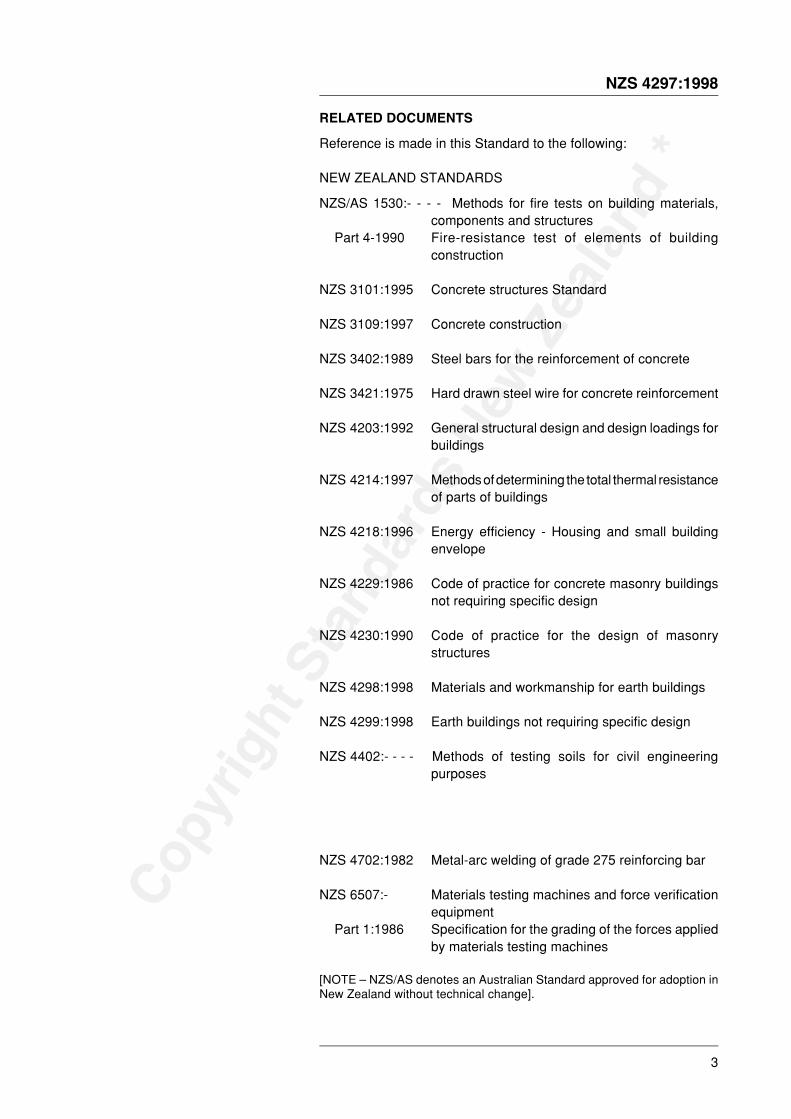
RELATED DOCUMENTS
Reference is made in this Standard to the following:
NEW ZEALAND STANDARDS
NZS/AS 1530:- - - - Methods for fire tests on building materials,components and structures
Part 4-1990 Fire-resistance test of elements of buildingconstruction
NZS 3101:1995 Concrete structures Standard
NZS 3109:1997 Concrete construction
NZS 3402:1989 Steel bars for the reinforcement of concrete
NZS 3421:1975 Hard drawn steel wire for concrete reinforcement
NZS 4203:1992 General structural design and design loadings forbuildings
NZS 4214:1997 Methods of determining the total thermal resistanceof parts of buildings
NZS 4218:1996 Energy efficiency - Housing and small buildingenvelope
NZS 4229:1986 Code of practice for concrete masonry buildingsnot requiring specific design
NZS 4230:1990 Code of practice for the design of masonrystructures
NZS 4298:1998 Materials and workmanship for earth buildings
NZS 4299:1998 Earth buildings not requiring specific design
NZS 4402:- - - - Methods of testing soils for civil engineeringpurposes
NZS 4702:1982 Metal-arc welding of grade 275 reinforcing bar
NZS 6507:- Materials testing machines and force verificationequipment
Part 1:1986 Specification for the grading of the forces appliedby materials testing machines
[NOTE – NZS/AS denotes an Australian Standard approved for adoption inNew Zealand without technical change].
Copy
right
Sta
ndar
ds N
ew Z
ealan
d *
4
NZS 4297:1998
AUSTRALIAN STANDARDS
AS 3610-1995 Formwork for concrete
AS 3700-1988 Masonry in buildings
BRITISH STANDARD
BS EN ISO 10319 Geotextiles. Wide-width tensile test
OTHER PUBLICATIONS
CSIRO Australia (Division of Building, Construction and Engineering).Bulletin 5: Earth-wall construction (4th edition, 1987).
New Zealand Building Industry Authority Approved DocumentB1 Structure, Verification Method 4: Foundations (September 1993).
New Zealand National Society for Earthquake Engineering, TheAssessment and Improvement of the Structural Performance ofEarthquake Risk Buildings, (June 1996).
UBC. Uniform Building Code, International Conference of BuildingOfficials, 1994.
Dowrick, D.J. Seismic Hazard Estimates for the Auckland Area, andTheir Design and Construction Implications, Bulletin of NZNSEEVol. 25, No. 3, September 1992.
Oliver, D. and Whybrid, D. Commercial Engineered AggregateConstruction, Proceedings of Economics in Building Conference,Brisbane, Australia, September 1991.
Yttrup, P. Strength of Earth Masonry (Adobe) Walls Subjected toLateral Wind Forces, Proceedings, 7th International Brick MasonryConference, Melbourne, February 1985.
The users of this Standard should ensure that their copies of theabove-mentioned New Zealand Standards or of overseas Standardsapproved as suitable for use in New Zealand are the latest revisionsor include the latest amendments. Such amendments are listed in theannual Standards New Zealand Catalogue which is supplemented bylists contained in the monthly magazine Standards issued free ofcharge to committee and subscribing members of Standards NewZealand.

Copy
right
Sta
ndar
ds N
ew Z
ealan
d *
NZS 4297:1998
5
FOREWORD
GeneralThis standard and the associated NZS 4298 Materials andworkmanship for earth buildings and NZS 4299 Earth buildings notrequiring specific design extend the range of construction and structuraldesign standards to cater for the growing interest in earth building.Earth is becoming increasingly important in the context of the moderndesire for construction materials which are less highly processed andhave low toxicity. These standards formalize the current state-of-the-artknowledge of design and construction using a building method thathas provided satisfactory shelter to millions of people around theworld over many centuries. As earth is a heavy, low-strength material,its use in construction is expected to essentially be limited to singlestorey walls and ground floors.
The enthusiastic support of Yvonne Rust as a prime promoter of theneed for earth building standards in New Zealand is recognized andthe role of the Earth Building Association of New Zealand in supportingthe development of this suite of standards is acknowledged. Manyother people and organizations, too numerous to name have alsomade valuable contributions.
Earth wall construction includes a diverse range of techniques to buildeither monolithic walls or ones made from individually laid bricks. Theaction of the complete wall in respect of strength, deformation anddamage depends very much on the standard of workmanship, and, inthe case of earth brick walls, the strength and durability of theindividual components and their arrangements. Frequently earthbuildings are constructed from local soils available near the constructionsite. Because of these variables, and because of the restrictedavailability (compared with other materials) of rigorous laboratory testresults, the performance of some elements under severe deformationis less well known or predictable than with other materials. However,earth wall construction is one of the oldest building techniques in theworld and earth walls have performed adequately in many situations.
These three new standards have been prepared with the intention ofseeking Building Industry Authority acceptance for referencing in the
need for versatility and flexibility with the need to keep it simple andcompact. The scope of these standards therefore excludes itemssuch as vaults and domes and walls which curve for lateral stability.The fact that something is not covered by a standard does not meanit is prohibited. What it does mean is that if one is wishing to build, saya dome, some other means of proving compliance with therequirements of the Building Code will need to be found. Such proofcan rely in part but not solely on these standards.

Copy
right
Sta
ndar
ds N
ew Z
ealan
d *
6
NZS 4297:1998
The process of earth building usually involves the following steps, notnecessarily in this order:
(1) Locate suitable building site.(2) Select a preferred earth building technique.(3) Consider suitability of local or nearby subsoils for various
construction methods.(4) Carry out field tests of possible construction soils to check their
suitability for the preferred construction method. Modify methodif necessary.
(5) Carry out pre-construction testing of earth building material.Modify mix as required.
(6) Design building and obtain building consent.(7) Carry out site work and building construction including quality
control testing.(8) Obtain Code Compliance Certificate.
The manner in which the three standards cover these steps is set outbelow.
Engineering design of earth buildingsNZS 4297 is primarily aimed at structural and performance aspects ofstep 6. Together with NZS 4298, it gives limitations to consider forsteps (1), (2), (3), (4), (5) and (7). It is intended for use by structuralengineers. Other publications and expert help can provide additionaladvice covering all these points and issues of aesthetics.
In New Zealand, the seismic provisions of NZS 4297 will governdesign in most cases. Many of the structural design principles arechosen to be similar to those for masonry (reinforced or unreinforced)and reinforced concrete, and it is assumed that users of this standardwill have a knowledge of design in these materials. However, earthhas unique characteristics that need to be considered apart fromother forms of masonry.
Limit State Design Principles have been used in the formulation of thisstandard to be consistent with other material design standards.Durability is important and is covered by a design method whichrelates required durability test results to the annual rainfall andexposure of a building site.
Out-of-plane loading on unreinforced vertically spanning walls hasbeen approached as ultimate limit state design based on the failuremode of walls at large deformation. Earthquake loads are analysedusing the energy method proposed by the New Zealand NationalSociety for Earthquake Engineering for strength assessment ofunreinforced masonry earthquake risk buildings.
Materials and workmanship for earth buildingsNZS 4298 sets out requirements for the materials and workmanshiprequirements for the use of unfired earth in the form of adobe, pressedearth brick, rammed earth or poured earth. NZS 4298 gives significanthelp for steps 4, 5, 6 and 7 noted above. It applies to buildings which
Copy
right
Sta
ndar
ds N
ew Z
ealan
d *
NZS 4297:1998
7
are designed in accordance with NZS 4297 Engineering design ofearth buildings and NZS 4299 Earth buildings not requiring specificdesign.
Commentary to this standard takes heed of the long history ofsuccessful earth building worldwide. A feature of this experience isthe diversity of building methods.
It is necessary to demonstrate that earthen materials used (with orwithout admixtures) produce results meeting at least the minimumstandards of strength and durability. Tests and the required resultsare detailed so that assurance can be given that the earth buildingmaterial will meet building code requirements.
Earth buildings not requiring specific designNZS 4299 is the earth building equivalent of NZS 3604 but with itscoverage limited to foundations, floor slabs and walls. It is intendedthat owner-builders or supervising owners with appropriateexperienced help will be able to use NZS 4299 alongside NZS 4298to carry out steps (1) to (8).
Again balancing the need for versatility and flexibility with the need forsimplicity has produced restrictions on the scope of buildings covered.More ambitious structures can be designed by a structural engineerusing NZS 4297.
REVIEW OF STANDARDS
Suggestions for improvement of this Standard will be welcomed.

Copy
right
Sta
ndar
ds N
ew Z
ealan
d *
8
NZS 4297:1998 NOTES

Copy
right
Sta
ndar
ds N
ew Z
ealan
d *
NZS 4297:1998
9
NEW ZEALAND STANDARD
ENGINEERING DESIGN OF EARTH BUILDINGS
1 GENERAL
1.1 ObjectiveThe objective of this Standard is to provide for the structural and durability design of earth buildings. TheStandard is intended to be approved as a means of compliance with clauses B1 and B2 of the NewZealand Building Code.
1.2 Scope
1.2.1The scope of this Standard is limited to unfired earthen wall building materials defined herein as adobe,pressed brick, poured earth or rammed earth and which contain clay and silt and which rely on the clayand silt particles present to achieve satisfactory performance with or without chemical stabilization.Earth building materials to which this Standard applies shall comply with NZS 4298 Materials andworkmanship for earth buildings.
C1.2.1This Standard sets minimum criteria. Parties are at liberty to set higher standards for any mattersreferred to in this Standard.
1.2.2Earth construction in accordance with this Standard shall not exceed 6.5 m in height from the top of thefooting to the top of the earth wall.
C1.2.2Design using procedures and/or material properties not described in this Standard may be carriedout when it can be shown by one of the following methods that the elements so designed haveadequate performance at the serviceability limit state and at the ultimate limit state:
(a) A special study; or
Aspects of designs which rely on any of (a) to (d) above are outside the scope of this Standard asa means of compliance with the New Zealand Building Code and must be treated as alternativesolutions.
The purpose of this clause is to acknowledge new design practices and the use of newly developedmaterial properties that may go further than this Standard permits, provided that the acceptabilityof such methods or approaches can be clearly demonstrated by way of the options listed.
Alternative design methods, material properties or structural systems must be supported by oneor more thorough experimental studies, or demonstrated service history. ➤
Copy
right
Sta
ndar
ds N
ew Z
ealan
d *
10
NZS 4297:1998
Compliance of alternative solutions with the New Zealand Building Code may be required to bedemonstrated when seeking a building consent.
Cement as a stabilizer may contribute substantially to strength in mixtures with a high proportionof sand. Where strength is almost entirely reliant on cement or other stabilizer, the masonrystandard or the standard appropriate to that material should be used.
1.2.3This Standard applies to earth wall items including house and building walls, boundary fences,outbuildings, garden walls, furniture, footings, fireplaces and such like. This Standard also coverscomponents of any of the foregoing including bricks, pieces and such like.
C1.2.3Retaining walls are excluded from this Standard.
1.2.4This Standard applies to New Zealand and its offshore islands.
1.3 Interpretation
1.3.1For the purposes of this Standard the word “shall” refers to practices that are mandatory for compliancewith this Standard, while the word “should” indicates a recommended practice.
1.3.2Cross-references to other clauses or clause subdivisions within this Standard quote the number only,for example: “... as required by 3.3.2.3(d) for shored construction”.
1.3.3The full titles of reference documents cited in this Standard are given in the list of Related documentsimmediately preceding the Foreword.
1.3.4Clauses prefixed by “C “ and printed in italic type are comments, explanations, summaries of technicalbackground, recommended practice or suggest approaches which satisfy the intent of the Standard.Corresponding mandatory clauses are not always present. They are not to be taken as the only orcomplete interpretation of the corresponding clause nor should they be used for determining in any waythe mandatory requirements of compliance within this Standard. The Standard can be complied withif the comment is ignored.
mandatory clauses. This is to enhance the relatively small pool of earth building experience andas a means of meeting the challenge of writing this first performance based suite of earth buildingstandards. Accordingly, the unusual format of having commentary clauses which have nocorresponding mandatory clause has been adopted .
1.3.5Provisions in this Standard that are in non-specific or in unquantified terms (such as where provisionsare required to be appropriate, adequate, suitable, relevant, satisfactory, acceptable, applicable or thelike and the Standard does not describe how to achieve this) are outside the scope of this Standard asa means of compliance with the New Zealand Building Code and must be treated as alternative solutions.
Mas
ters
pec
(281
998)
subs
crib
ers
are
licen
sed
tote
rmpo
raril
ydo
wnl
oad
this
docu
men
tand
may
pri
Copy
right
Sta
ndar
ds N
ew Z
ealan
d *
NZS 4297:1998
11
1.3.6The terms “normative” and “informative” have been used in this Standard to define the application of theAppendix to which they apply. A “normative” appendix is an integral part of a Standard, whereas an“informative” appendix is only for information and guidance. (There are no informative appendices inthis Standard).
1.4 Construction reviewConstruction review shall be carried out in accordance with clause 1.4 of NZS 4298.
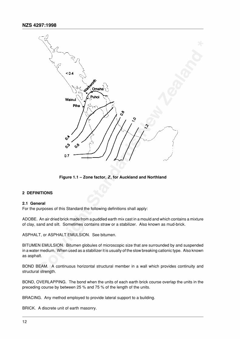
1.5 Seismic zonesSeismic loads shall be in accordance with NZS 4203 General structural design and design loadings forbuildings with the following proviso that for Auckland and Northland, the seismic design shall be asfollows:
For areas north-west of the 0.6 contour for the seismic zone factor, Z, shown on figure 4.6.2 of NZS 4203,the seismic zone factor shall be determined from figure 1.1 with the proviso that the minimum value ofthe seismic zone factor shall be 0.40.
C1.5The concept of reduced requirements for Auckland and Northland are based on the paper SeismicHazard Estimates for the Auckland Area, and Their Design and Construction Implications by DavidJ. Dowrick, first presented at the Pacific Conference on Earthquake Engineering, Auckland,November 1991. (Paper reprinted in revised form in the Bulletin of the N.Z. National Society forEarthquake Engineering Vol. 25, No. 3, September 1992).
Seismic design for Northland would normally be for detailing for robustness and to avoid collapsein the extreme seismic event.
1.6
Copy
right
Sta
ndar
ds N
ew Z
ealan
d *
12
NZS 4297:1998
Figure 1.1 – Zone factor, Z , for Auckland and Northland
2 DEFINITIONS
2.1 GeneralFor the purposes of this Standard the following definitions shall apply:
ADOBE. An air dried brick made from a puddled earth mix cast in a mould and which contains a mixtureof clay, sand and silt. Sometimes contains straw or a stabilizer. Also known as mud-brick.
ASPHALT, or ASPHALT EMULSION. See bitumen.
BITUMEN EMULSION. Bitumen globules of microscopic size that are surrounded by and suspendedin a water medium. When used as a stabilizer it is usually of the slow breaking cationic type. Also knownas asphalt.
BOND BEAM. A continuous horizontal structural member in a wall which provides continuity andstructural strength.
BOND, OVERLAPPING. The bond when the units of each earth brick course overlap the units in thepreceding course by between 25 % and 75 % of the length of the units.
BRACING. Any method employed to provide lateral support to a building.
BRICK. A discrete unit of earth masonry.
Copy
right
Sta
ndar
ds N
ew Z
ealan
d *
NZS 4297:1998
13
CELL. A hole through or along an earth brick unit in the plane of a wall.
CHARACTERISTIC STRENGTH. An estimate of the lower 5 % value determined with 75 % confidencefrom tests on a representative sample of full size specimens.
CHARACTERISTIC UNCONFINED COMPRESSIVE STRENGTH. The characteristic strengthdetermined from compressive strength tests to which an aspect ratio correction factor has been applied.
CINVA BRICK. A pressed earth brick meeting the dimensional and strength requirements of section 6of NZS 4298.
CLAY. A fine grained, natural, earthy material composed primarily of hydrous aluminium silicates withgrain diameters less than 0.002 mm.
COLD JOINT. In rammed earth construction, the joint which occurs when construction has beeninterrupted long enough for some degree of drying or curing to take place before fresh material is placed.
COLUMN. An isolated, reinforced, vertical load-bearing member subjected primarily to compressionhaving a cross section with a length to breadth ratio between 3 and 0.33.
COMPRESSIVE STRENGTH. A physical property of a material that indicates its ability to withstandcompressive forces, usually expressed in kPa or MPa.
CONTROL JOINT. A joint necessary to allow an earth wall to expand and contract or otherwise move.
CURING. The action of water acting over time in a stabilized soil mass causing the mass to be cementedtogether by the stabilizer.
DAMP PROOF COURSE. A durable waterproof material placed between materials as a protectionagainst moisture movement. A painted on or a sheet damp proof course is referred to as a damp proofmembrane.
DESIGN ENGINEER. A person who, on the basis of experience or qualifications, is competent to designstructural elements of the building under consideration to safely resist the design loads or effects on thebuilding.
DIAPHRAGM. A member such as a floor or ceiling capable of transferring loads in its own plane toboundary members.
DUCTILITY. The ability of a material, structural component or structure to deform or dissipate energybeyond its elastic limit i.e. into the post-elastic range.
DURABLE. Resistant to wear and decay. Durability has a corresponding meaning.
EARTH (for earth building). Natural sub-soil comprised of varying percentages of clay, silt, sand andgravel which is unfired and is free of significant organic matter.
ELASTIC RESPONSE. The response range of a structure where the deformation is in direct proportionto the force applied (i.e. the material, structural component or structure obeys Hooke’s law.)
Copy
right
Sta
ndar
ds N
ew Z
ealan
d *
14
NZS 4297:1998
EROSION. The physical and chemical processes by which earth building material is worn away. Itincludes the processes of weathering and mechanical wear.
FLEXURAL TENSILE STRENGTH. (Also known as modulus of rupture or flexural strength). Flexuralstrength of the material as measured in accordance with Appendix J of NZS 4298.
FLUE. An enclosed continuous horizontal or vertical space in an earth brick element formed by the cellsof the units which make up that member.
FOOTING. That portion of a foundation bearing on the ground. It may be spread out to provide anincrease in bearing area or an increase in stability.
FOUNDATION. Those parts of a building transmitting and distributing loads to the ground, through afooting.
FOUNDATION WALL. See WALL.
GABLE. The triangular part of an outside wall between the planes of the roof and the lines of the eaves.
GROUND LEVELFINISHED GROUND LEVEL. The ground level after all backfilling, landscaping and surface pavinghave been completed.
GROUT. A liquid mixture of cement, sand and water, with or without small aggregate, used to fill cavitiesafter bricks and reinforcing have been placed.
LIMIT STATESERVICEABILITY LIMIT STATE. The state at which a structure becomes unfit for its intended usethrough deformation, vibratory response, degradation or other operational inadequacy.
ULTIMATE LIMIT STATE. The state at which the strength or ductility capacity of the structure isexceeded, when it cannot maintain equilibrium and becomes unstable.
MORTAR. The bedding material in which earth brick units are bedded.
PARTITION. See WALL.
P-DELTA EFFECT. Refers to the structural actions induced as a consequence of gravity loads beingdisplaced laterally due to the action of earthquake or wind forces or other effects.
PERPEND. The perpendicular joint between two bricks.
PIER. (Also known as pilaster). A member similar to a column except that it is bonded into a wall. Thethickness of a pier includes the thickness of the associated wall.
POST-ELASTIC BEHAVIOUR. The large deformations accompanying small increase in force after theelastic limit has been reached.
POURED EARTH. An earth building technique in which earth and water, with or without stabilizer, ispoured into moulds in place on the wall being constructed. The moulds are removed when the earth isstrong enough to maintain its shape.
Copy
right
Sta
ndar
ds N
ew Z
ealan
d *
NZS 4297:1998
15
PRESSED EARTH BRICK (or PRESSED BRICK). An earth brick that is made in a mechanical press,either machine operated or hand operated.
RAMMED EARTH. Damp or moist soil, with or without stabilizer, that is tamped in place betweentemporary moveable formwork. Also known as pise.
RAMMED EARTH WALL PANEL. A section of rammed earth wall being of full height of the finishedsection but of length that is built at one stage.
REINFORCED EARTH CONSTRUCTION. Any earth structure into which reinforcing is so bedded andbonded that the two materials act together in resisting forces.
REINFORCEMENT. Any form of steel reinforcing rod, bar or mesh that complies with the relevantrequirements of NZS 3109, or plastic or other material cited in this Standard capable of imparting tensilestrength to the earth building material.
SAND. Individual rock or mineral fragments that range in diameter from 0.06 mm to 2.0 mm.
SHRINKAGE. The decrease in volume of earth material or mortar caused by curing or the evaporationof water. Expressed as a percentage of linear dimension.
SILT. Individual mineral particles in a soil that range in size from the upper limit of clay (0.002 mm) tothe lower limit of fine sand (0.06 mm).
SOIL. See earth.
SPACING. The distance at which members are spaced measured centre to centre.
STABILIZATION. The improvement of the performance of earth building material properties by theaddition of materials which bind the earth particles. Stabilization may increase the resistance of earthto moisture, reduce volume changes or improve strength or durability.
STABILIZER. A material which is used for stabilization.
STABILIZED ADOBE. Adobe bricks which have a stabilizer added, typically cement or bitumenemulsion.
STABILIZED POURED EARTH. Poured earth which has had a stabilizer added, usually cement.
STRENGTHDESIGN. The nominal strength of a member section multiplied by the appropriate strength reductionfactor.
NOMINAL. The theoretical strength of a member section using the section dimensions as detailedand the characteristic strengths of the reinforcement and the strength of the earth.
OVERSTRENGTH. Overstrength is used in seismic design. This increased value takes into accountfactors that may contribute to strength such as higher than specified strengths of the steel and earth,strain hardening and additional reinforcement placed for construction and otherwise unaccounted forin the calculations.
Copy
right
Sta
ndar
ds N
ew Z
ealan
d *
16
NZS 4297:1998
WALLEXTERNAL WALL. An outer wall of a building.
LOADBEARING WALL. A wall supporting vertical loading from floors, ceiling joists, roof, or anycombination thereof.
NON-LOADBEARING WALL. A wall other than a loadbearing wall.
PARTITION. A light timber wall which is used within the building.
STRUCTURAL WALL. Any wall which because of its position and shape contributes to the rigidityand strength of the building.
WALL THICKNESS. Minimum thickness of wall remaining after any chasing, raking or tooling of mortarjoints.
2.2 NotationIn this Standard, symbols shall have the following meanings. Other symbols, or other meanings forsymbols listed below, that are defined immediately adjacent to formulae or diagrams, shall apply onlyto those formulae or diagrams. Use of these symbols is subject to the following:
(a) Where non-dimensional ratios are involved, both the numerator and denominator are expressed inconsistent units; and
(b) Dimensional units used, expressions or equations shall be consistent unless otherwise specified.
Ab area of earth cross section
Ade effective area of dispersion of the concentrated load in the member at mid-height
Ads bearing or dispersion area of the concentrated load
Ast area of reinforcing steel
As
Asv
A1
a width of stress block at ultimate limit state
acr, a1/2, a3/4, au acceleration at cracking, 1/2 cracked, 3/4 cracked and ultimate momentcondition respectively
av coefficient for assessing slenderness ratio
a1 distance from the end of the wall or pier to the nearest end of the bearing area
b eaves width (mm)
it bu
t not
mor
e th
an 1
0% o
f the
doc
umen
ts s
ubsc
Copy
right
Sta
ndar
ds N
ew Z
ealan
d *
NZS 4297:1998
17
Cpi basic horizontal seismic coefficient for a part at level i from NZS 4203
db bar diameter
d depth of section in the direction of shear
Ee modulus of elasticity of earth
Es modulus of elasticity of reinforcing steel
e eccentricity of vertical force
fd compressive stress acting on a section under the design loading – N */Ab
fe compressive strength of earth wall construction
fea adjusted compressive strength for multiple brick construction
feb tensile flexural bond strength
fes shear strength of earth
fet flexural tensile strength of earth
fn total nominal shear stress
fsy lower yield strength of shear reinforcement
fy lower characteristic yield strength of reinforcement
f 'uc unconfined compressive strength of sample
h height of earth wall in metres above the plane being considered; orheight of a member; orclear height of a member between horizontal lateral supports; orfor a member without top horizontal support, the overall height from the bottom lateral support;
km multiple brick factor
kv shear factor
k1 rainfall factor
k2 wall orientation factor
k3 eaves factor
Copy
right
Sta
ndar
ds N
ew Z
ealan
d *
18
NZS 4297:1998
k4 locality factor
L clear length of a wall between vertical lateral supports; orfor a wall without a vertical support at its end or at a control joint, the length to that unsupportedend or control joint; orclear length of the wall or pier
Le dispersion zone length
Mch design flexural strength of the wall
Mcr, M1/2, M3/4, Mu moment in wall at cracking, 1/2 cracked, 3/4 cracked and ultimate conditionrespectively
Mn nominal flexural strength of a section
M* design bending moment acting on the cross section of a member at the ultimate limitstate determined from loads complying with NZS 4203
M*dh design horizontal flexural bending moment on a wall
N* design axial load at the ultimate limit state determined from NZS 4203
No nominal compressive strength of an earth cross section short enough for slendernesseffects to have no influence
P gravity load per unit length at top of wall
p annual rainfall (mm)
R thermal resistance in m2.oC/Wvertical reaction at crack
Sr slenderness ratio
Sn nominal strength at the ultimate limit state for the relevant action of moment, axial load, shear and torsion
S*
s
t thickness or depth of wall perpendicular to the axis under consideration
tw overall dimensions thickness of a wall or isolated pier, taking into account any jointraking which is deeper than 3 mm
Vn nominal shear strength of a section
V(z) site wind speed at height z for the direction under consideration at the ultimate limitstate (m/s)
Copy
right
Sta
ndar
ds N
ew Z
ealan
d *
NZS 4297:1998
19
V * design shear force acting on the cross section of a member at ultimate limit statedetermined from NZS 4203
W self weight of wall under investigation
wcr, w1/2, w3/4, wu distributed lateral load required to induce corresponding wall moment
Z earthquake zone factor
Zu the lateral section modulus of the earth wall based on the gross cross section
γ density of wall material
Δcr, Δ1/2, Δ3/4, Δu displacement at centre of wall at cracking, 1/2 cracked, 3/4 crackedand ultimate conditions
δ coefficient of variation
µ structural ductility factor, as defined in NZS 4203
φ capacity reduction factor
3 PERFORMANCE CRITERIA
3.1 Notation
R thermal resistance in m2.oC/W
3.2 DurabilityCompliance with this section is necessary to satisfy the requirements of clause B2 of the New ZealandBuilding Code to provide for a building life of not less than 50 years.
3.2.1An earth wall will be deemed to comply with the durability performance criteria if, provided that normalsurface maintenance has been carried out, its thickness has not decreased by more than 5 % nor bymore than 30 mm at any point during the building’s life.
Normal maintenance of earth building material shall include the repair of damage or deterioration of thewall surface including any surface coating and the removal of any source of moisture which is capableof causing localised elevation of earth wall moisture content. Such sources may include plumbing orroofing leaks, channelling of rainwater, bridging or other loss of integrity of the damp proof course,vegetation or build up of ground levels. Repair of earth building material is to be carried out using thesame material as that from which the earth wall is constructed and be applied in accordance with
the provisions of NZS 4298. Surface coatings which are impervious to water vapour and air shall notbe used.
C3.2.1 GeneralEarth walls are particularly susceptible to moisture, whether this is from rising damp, water ingressfrom the top, driving rain, water splashing, or moisture generated internally in a building. For thisreason it is important that any design considers the need to protect earth walls from excessivemoisture. Care is to be taken with all weathering details including flashings and eaves protectionof wall tops. Any applied coatings or surface finishes shall provide permeability to prevent moisturebecoming trapped inside an earth wall.
➤
Copy
right
Sta
ndar
ds N
ew Z
ealan
d *
20
NZS 4297:1998
A structure is durable if it withstands wear and deterioration throughout its intended life without theneed for undue maintenance. Deterioration of earth walls depends on the severity of wind-drivenrain, on the orientation of the wall, on the weather resistance of the wall material, on surfacecoatings, and on the surface finish and on the degree of stabilization of the material.
3.2.2Walls shall be considered satisfactory in terms of 3.2.1 above if the erodibility index of a sample (asdetermined in accordance with Appendices D or E of NZS 4298) is less than or equal to the LimitingErodibility Index determined in accordance with Appendix A of this Standard.
3.3 Strength
3.3.1 Limit state for strength
3.3.1.1The required characteristic unconfined compressive strength of wall units or rammed earth samplesshall be stated on the drawings and in the specifications.
3.3.1.2The characteristic unconfined compressive strength shall be determined in accordance with AppendixB of NZS 4298.
3.3.2 TestingTesting shall be carried out in accordance with clause 2.3 of NZS 4298 for standard grade earth materialsand in accordance with clause 2.4 of NZS 4298 for special grade earth materials.
C3.3.2Standard grade earth materials are the minimum grade of earth materials to be used forconstruction complying with NZS 4299 or for specific designs in accordance with this Standardutilizing the design strengths of table 4.1.
The required testing includes both a testing regime for determining acceptable materials prior toconstruction commencing and quality control tests to be conducted during construction.
3.4 Shrinkage
C3.4.1 GeneralUnstabilized earth walls rely mainly on the presence of clay to maintain their integrity. The amountand type of clay present influences the amount of shrinkage that takes place as the walls or bricksdry out. Whilst the presence of shrinkage cracks in individual bricks may sometimes be a featureof adobe construction, there is a need to limit cracks in completed walls to an acceptable size.
due to the cement and clay content.
3.4.2Control joints shall be included to take account of shrinkage. Detailing shall ensure that movement atcontrol joints can take place whilst still maintaining structural integrity and water tightness. Crackingwhich does not affect structural integrity may be plastered.
C3.4.2Detailing of the frames for doors and windows needs to take account of both the vertical andhorizontal shrinkage of earth building materials. Limiting cracks to maintain integrity againstinsects is important but is not a Building Code requirement.
Copy
right
Sta
ndar
ds N
ew Z
ealan
d *
NZS 4297:1998
21
3.5 Thermal insulation
3.5.1Unless determined otherwise by testing in accordance with NZS 4214, R may be taken as given by 3.5.2.
3.5.2The static thermal resistance of walls consists of the thermal resistance of the wall material plus thethermal resistance to convection and radiation at the surfaces, the latter being expressed as a constant“air” resistance. For earth walls the thermal resistance, R, may be taken as 2.04 times the wall thicknessin metres plus 0.12. The units are in m2. oC/W.
C3.5.2The thermal performance of earth walls is greatly improved by the effect of thermal mass due toan effect known as “thermal lag”. The value of static thermal resistance given above can thereforebe taken as a conservative measure of the thermal performance of earth walls. The thermal lagfor earth walls is of the order of 7 to 10 hours for a 280 mm wall. At present there is no simple methodfor taking thermal lag into account but this Standard does not preclude the use of moresophisticated computer programs which deal with this.
A minimum external wall thickness of 280 mm is generally required to satisfy without additionalinsulation, the New Zealand Building Code requirements of clauses E3 and H1 for insulation. Insatisfying the Building Code requirements the whole building is to be considered. Referenceshould be made to NZS 4218.
3.6 FireClause 5.5.1 provides values of fire resistance ratings for earth wall construction.
4 GENERAL CONSTRUCTION AND DESIGN REQUIREMENTS
4.1 Notation
Ee modulus of elasticity of earth
Es modulus of elasticity of reinforcing steel
fe compressive strength of earth wall construction
fea
fn total nominal shear stress
f 'uc unconfined compressive strength of sample
h height of earth wall in metres above the plane being considered
km multiple brick factor
Z earthquake zone factor
δ coefficient of variation
µ structural ductility factor
Copy
right
Sta
ndar
ds N
ew Z
ealan
d *
22
NZS 4297:1998
4.2 ScopeThis section contains the general requirements for all types of earth buildings of brick type or solidhomogenous structure.
4.3 General principles and requirements for construction
4.3.1 Earth building materialsEarth building materials shall comply with NZS 4298.
4.3.2 Design objectivesIn addition to meeting the specific engineering design requirements of this section, the design engineershall take account of the shape and dimensions of walls and construction practices including methodsof positioning reinforcement and placing and compacting of grout.
C4.3.2Design and detailing should be such as to promote the following:
(a) Walls of consistent quality;
(b) Development of bond of grout to both reinforcement and bricks (where applicable);
(c) Control of shrinkage and settlement of earth and, where used, mortar and grout;
(d) Avoidance of corrosion of reinforcement;
(e) Minimizing of adverse weathering effects of types which adversely affect structural adequacyand serviceability.
4.4 Standard grade earth constructionEarth materials for standard grade earth construction shall comply with clause 2.3 of NZS 4298.
4.4.1 LimitationsStandard grade earth construction shall only be carried out within the following limitations:
(a) The floor live load on suspended floors shall not exceed 1.5 kPa or 2.0 kPa on domestic balconiesas provided for in NZS 4203. Suspended floors shall have a dead load of less than 0.9 kPa.
(b) Buildings shall be Category IV or V buildings as described in table 2.3.1 of NZS 4203.
(c) In areas where the NZS 4203 seismic zone factor is greater than 0.6 the ground floor plan area shallnot exceed:
(i) 600 m2 for single-storey earth buildings
(ii) 200 m2 for two-storey earth buildings
(iii) 300 m2 for two-storey buildings where the upper storey is constructed of timber and the wallsof the lower storey are of earth
(d) The total height of the earth wall, including any gable end, from the lowest concrete foundation topsurface adjoining shall not exceed 6.5 m.
4.4.2 Design strengthsStrengths used in design shall be as given in table 4.1.

Copy
right
Sta
ndar
ds N
ew Z
ealan
d *
NZS 4297:1998
23
Table 4.1 – Strengths (MPa) to be used for design of standard grade earth wall construction
Compressive strength (flexural, direct compression or bearing) fe = 0.5
Maximum total nominal shear stress fn = 0.09
Shear strength of earth for wind loadingand for seismic load with elastic response fes = 0.08
Shear strength of earth for limited ductile (µ = 2.0) seismic loading fes = 0.0
Shear strength of steel reinforced earth fes = 0.35
Tensile/flexural bond strength feb = 0.02
Flexural tensile strength fet = 0.1
C4.4.2A wide variety of bond strengths have been encountered by earth building practitioners. Unstabilizedearth brick construction has been found to have considerable bond strength, and values of 50 kPahave been measured, but zero bond strength has also been encountered. Up to 260 kPa bond hasbeen measured in cement stabilized in situ adobe construction. Up to 890 kPa flexural tensilestrength has been tested for cement-stabilized pressed brick. However, little is known about theas-built flexural strength of rammed earth panels and how this is affected by “cold joints” etc. Inview of all these uncertainties and variabilities therefore, designers may only use a higher tensile/flexural bond strength if substantiated by pre-testing.
The in-wall strengths of table 4.1 are less than the strength test results obtained in the laboratory.Modifications for aspect ratio, characteristic strength, and mortar effects as outlined in thisStandard all bring about reductions.
4.4.3 Multiple brick factor for out-of-plane wall strengthWhere an earth wall panel is 10 or more bricks long the compressive strength shall be increased by themultiple brick factor km
If the coefficient of variation (δ ) is established as 0.35 or higher from the test results of 30 or morespecimens, then km shall be taken as 1.3.
C4.4.3The compressive strength fe is based on statistical analysis. Where multiple bricks are workingin parallel the probability of one brick failing or causing significant strength loss is less. Weakerearth bricks have lower stiffness, allowing load sharing with stronger, stiffer bricks. Designstrengths for materials with δ > 0.35 are reduced significantly to allow for the material variation.Walls of these materials benefit the most from load sharing.

Copy
right
Sta
ndar
ds N
ew Z
ealan
d *
24
NZS 4297:1998
4.5 Special grade earth construction
4.5.1 Compressive and flexural strengthsThe compressive strength fe and the flexural tensile strength fet shall be established using the testmethods of the Appendices of NZS 4298.
Where fe is based on the testing of individual specimens rather than prisms with mortar joints thefollowing relationship between the unconfined compressive strength of the sample (f 'uc) and the wallstrength (fe) shall be taken as follows:
Adobe and poured or rammed earth fe = f 'uc
Pressed earth bricks (including cinva brick) fe = 0.5 x f 'uc
4.5.2 Brick compressive strength derived from flexural tensile strengthIn the absence of compression tests, where testing for flexural tensile strength to Appendix J of NZS4298 has been done, the compressive strength shall be calculated from the flexural tensile strength asfollows:
fe = 3.5 fet
C4.5.2The formulae for compression strength derived from flexural tensile strength are based onconservative test results. Compression tests are likely to give higher fe / fet ratios.
4.5.3 Joint strengthWhere the compressive strength is greater than 6 MPa, the joint strength shall be taken into account forearth brick walls. Such considerations are outside the scope of this Standard.
4.5.4 Shear strengthThe shear strength of earth, fes, shall be given by the greater of:
fes = 0.07 fe ............................................................................................................................................................. (Eq. 4-1)
or
fes = (70 + 5 h ) kPa ................................................................................................................. (Eq. 4-2)
where h is in metres.
4.5.5 Flexural tensile strengthIn the absence of flexural tensile strength test results, but where testing for compressive strength inaccordance with Appendix A of NZS 4298 has been carried out, the flexural tensile strength, fet, shallbe taken as 0.10 fe for earth building materials with a compressive strength less than 6 MPa. Formaterials with a strength of 6 MPa and above the flexural tensile strength shall be determined by testingin accordance with NZS 4298.
4.5.6 Modulus of elasticity of earthThe modulus of elasticity, Ee, for earth wall construction shall be taken as 300 x fe.
C4.5.6The modulus of elasticity of soil cement varies depending on the type of soil and increasesapproximately linearly with strength. This formula will give a low average estimate for silty soils.An appropriate higher value should be used if a low value will give non-conservative results.
Copy
right
Sta
ndar
ds N
ew Z
ealan
d *
NZS 4297:1998
25
For silty or poorly graded materials the Modulus of Elasticity lies in the range 120 kPa –3 GPa. Forsilty-sandy clays, and poorly graded sands 3 GPa – 7 GPa, silty sands and sandy clays nearer7 GPa, gravely soils 7 GPa – 20 GPa.
Where the modulus of elasticity is critical it should be established by test. Such testing shouldestablish the internal modulus of elasticity. Internal measurement, by deformation measuringequipment attached to the specimen, will give substantially higher values than the modulusmeasured from external deformation measurements because of test system effects.
4.5.7 Modulus of elasticity of steelThe modulus of elasticity, Es, of non-prestressed steel reinforcement shall be taken as 200 GPa.
4.6 General principles for design
4.6.1Earth walls shall be a minimum of 250 mm thick except for cinva brick walls which may be 130 mm thick.
C4.6.1Walls less than 280 mm may require additional insulation to meet thermal insulation requirementsof the New Zealand Building Code clauses E3 and H1.
4.6.2Maximum slenderness ratio, Sr, shall be as follows:
Earthquake zone factor: Z ≤ 0.6 Z > 0.6(a) Unreinforced loadbearing wall 10 6(b) Reinforced loadbearing wall 16 10(c) Unreinforced columns 4 3(d) Reinforced columns 8 6(e) Unreinforced non-loadbearing wall 12 8(f) Reinforced non-loadbearing wall 18 12(g) Reinforced cinva brick 24 16
Unreinforced walls higher than 3.3 m and unreinforced columns higher than 2.4 m shall have theirdimensions assessed by special study. Such a study is outside the scope of this Standard.
C4.6.2The values in 4.6.2 are recognized best practice based on data from overseas codes andexperience in New Zealand.
4.6.3Adequate lateral restraint shall be provided at wall tops by a diaphragm, bond beam, or other similardevice. Lateral restraints shall be constructed from timber, steel, reinforced concrete or reinforced
Such design is outside the scope of this Standard.
4.6.4Bracing shall be distributed around the building to provide for:
(a) Out of plane effects;
(b) Torsion at each floor level and of the building as a whole.
C4.6.4Designs should minimize the eccentricity of walls about the centre of mass of a building.
Copy
right
Sta
ndar
ds N
ew Z
ealan
d *
26
NZS 4297:1998
4.7 Principles and requirements additional to 4.6 for members designed for seismic loading
4.7.1 Methods of design
4.7.1.1To provide minimum resistance for the appropriate combination of gravity and seismic loads specifiedby NZS 4203, design methods of sections 5, 6, 7, 8 and 9 of this Standard which are applicable to thestructural systems shall be used.
4.7.1.2Limited ductile and elastic response methods are applicable, but ductile methods shall not be usedunless supported by a special study. Such special study is outside the scope of this Standard.
4.7.1.3In the case of limited ductile design, all the shear strength of the wall shall be supplied by the shearreinforcing i.e. the shear strength contribution of the earth shall be neglected.
C4.7.1.3Designers should note that the overall shear strength of the gross wall area is limited by theprovisions of table 4.1 and 4.7.1.3.
4.7.1.4The interaction of all structural and non-structural elements which, due to seismic displacements, mayaffect the response of the structure or the performance of non-structural elements, shall be consideredin the design of that structure.
4.7.1.5Consequences of failure of elements that are not a part of the intended primary system for resistingseismic forces shall also be considered.
4.7.1.6Floor and roof systems in buildings shall be designed to act as horizontal structural elements, whererequired, to transfer seismic forces to frames or structural walls.
C4.7.1.7Where higher strength materials are used, the more detailed methods of AS 3700 or NZS 4230 maybe used where materials have similar strengths to fired clay or concrete masonry to utilize higherstrengths than are available with this Standard. Designs so based are outside the scope of thisStandard.
4.7.1.8Structural systems and design methods, other than those covered in this Standard, may be used if it canbe shown by analysis or experiment based on accepted engineering principles, that adequate strength,stiffness, and ductility for the anticipated seismic movements have been provided. Designs so basedare outside the scope of this Standard.
C4.7.1.8Post-and-beam construction is one such building system that is covered by this clause.
Copy
right
Sta
ndar
ds N
ew Z
ealan
d *
NZS 4297:1998
27
4.7.2 Seismic loading
4.7.2.1In the derivation of the lateral seismic loading to be considered with the appropriate factored gravity load,the structural ductility factor, µ , as defined in NZS 4203 shall be taken as 1.0 for unreinforced walls andelastically responding reinforced walls and 2.0 for reinforced walls designed for limited ductility. Theexception is cinva brick walls designed for limited ductility which shall be designed for a structural ductilityfactor of 1.25.
4.7.2.2The structural performance factor, Sp, as defined in NZS 4203 shall be taken equal to 0.67.
4.7.2.3Where appropriate, effects of concurrency in two-way horizontal force resisting systems shall complywith requirements of NZS 3101.
4.7.3 Assumptions and methods of analysis
4.7.3.1In determining the minimum strengths for members designed for the maximum effects of factored staticloads determined by elastic analysis, or for effects derived from other analysis, as permitted by NZS4203, the capacity reduction factors specified in section 5 shall be used.
4.7.3.2Redistribution of the design moments obtained from elastic analyses shall not be allowed.
4.7.4 Material properties
4.7.4.1Structural ductility factors shall be as in 4.7.2.1.
4.7.4.2Earth shall be pre-tested to the requirements of NZS 4298 demonstrate the strengths to be used indesign if higher strengths than those given by 4.4.2 are to be used.
4.7.4.3The grade of reinforcement used shall be only that specified except that substitution of higher gradesof reinforcement may be made provided that there are no detrimental effects on structural performance.
C4.7.4.3
violated promoting the possibility of brittle failure of earth in place of ductile yielding of steel.
4.7.5 Stiffness
4.7.5.1Allowances shall be made for the effects of cracking on the stiffness of various structural members,where applicable, for the purpose of estimating periods of vibration and structural deformations, tocomply with the requirements of NZS 4203.

Copy
right
Sta
ndar
ds N
ew Z
ealan
d *
28
NZS 4297:1998
4.7.5.2In the estimation of stiffness or deformations of shear walls and other deep members, allowance shallbe made for shear distortions, and distortions of anchorages and foundations, where appropriate.
C4.7.6Structures with limited ductility. In structures with limited ductility, the system as a whole or theprimary lateral load resisting components are not considered to be capable of sustaining theinelastic displacements that are expected in fully ductile structures, without significant loss ofstrength or reduction in energy dissipating capacity.
4.7.7 Elastically responding structuresStructures which are expected to respond elastically to large earthquake motions, in accordance with4.7.1.1, shall be designed to withstand loads derived assuming elastic response. They are exempt fromthe additional seismic requirements of all relevant sections of this Standard, provided that theearthquake design load used is that specified by NZS 4203 for these types of structures. For suchstructures strength design procedures in accordance with the general principles and requirements of therelevant sections of this Standard shall be used.
4.7.8 FoundationsGeneral design principles for concrete foundations shall comply with the requirements of sections 4 and15 of NZS 3101.
4.7.9 Structures incorporating mechanical energy dissipating devicesGeneral design principles shall comply with the requirements of NZS 3101.
5 STRENGTH AND SERVICEABILITY
5.1 Notation
fy lower characteristic yield strength of reinforcement
h clear height of a member between horizontal lateral supports; orfor a member without top horizontal support, the overall height from the bottom lateral support
L clear length of a wall between vertical lateral supports; orfor a wall without a vertical support at its end or at a control joint, the length to thatunsupported end or control joint
Sn
S*
φ
5.2 General
5.2.1Structures and structural members shall be designed to have design strengths at least equal to therequired strengths calculated for the factored loads and applied forces in such combinations as arestipulated in NZS 4203.
5.2.2Structural members shall meet all requirements of this Standard to ensure adequate performance at theserviceability limit state and at the ultimate limit state in such combinations as are stipulated in NZS 4203.
Copy
right
Sta
ndar
ds N
ew Z
ealan
d *
NZS 4297:1998
29
5.3 Ultimate limit state
5.3.1 General requirements
5.3.1.1The design strength of a member or cross section in terms of load, moment, shear, or stress shall betaken as the nominal strength, Sn, calculated in accordance with the requirements and assumptions ofthis Standard, multiplied by a capacity reduction factor, φ.
The design strength of a member or cross section shall be equal to or greater than the applied action,S*, resulting from the design loads of NZS 4203.
5.3.1.2In general terms 5.3.1.1 is expressed as:
S* ≤ φSn .................................................................................................................................................................... (Eq. 5.1)
where S is replaced by the actions of moment, axial force, shear or torsion as appropriate.
C5.3.1.2These values are similar to those for concrete masonry.
5.3.1.3 Capacity reduction factorsThe capacity reduction factors shall be as follows:
φ = 0.60 for axial compression and bearing
φ = 0.80 for flexure
φ = 0.70 for shear
φ = 0.70 for metal connections embedded in earth.
φ = 0.60 for flexure determined using Appendix B.
5.3.1.4Design shall not be based on a lower characteristic yield strength for reinforcing steel, fy , in excess of485 MPa.
5.3.2 Additional requirements for members designed for seismic loadingWhen the design moments, axial loads, or shear forces for a section are derived from overstrengths of
5.4.1 Deflection
5.4.1.1Members subject to flexure shall be designed to have adequate stiffness to limit deflections or anydeformations which may adversely affect the serviceability of the structure under service loads to thevalues required by NZS 4203.
5.4.1.2The minimum thickness in the horizontal direction, where the walls are not supporting or attached topartitions or other construction likely to be damaged by large deflections, shall not be less than the

Copy
right
Sta
ndar
ds N
ew Z
ealan
d *
30
NZS 4297:1998
following (unless computation of deflections indicates that lesser thickness may be used without adverseeffects):
Simply supported h /18 or L/18
One end continuous h /21 or L/21
Both ends continuous h /22 or L/22
Cantilever h /8 or L/8
C5.4.1.2These values are based on values given in AS 3700 and NZS 4230.
5.4.1.3Computed deflections for seismic design under elastic response shall be limited to h /150.
5.4.2 Shrinkage and thermal control jointsWhere control of cracking is required, the position of joints shall be as detailed in clause 2.12 of NZS 4298and shall be detailed in the drawings and specifications.
5.5 Other considerations
5.5.1 Fire resistanceThe fire resistance of earth construction shall be taken as 120/120/120 for a wall thickness of 150 mmunless proved greater than that by testing in accordance with NZS/AS 1530.
C5.5.1CSIRO (Australia) Bulletin 5 gives further details on fire tests and AS 3700 on fire design.
5.5.2 Water penetrationThe structure shall be detailed such that the effects of water and moisture penetration do not affect thedurability of the structure nor its contents. Such detailing is outside the scope of this Standard.
5.5.3 Shear on bolted connections in earth
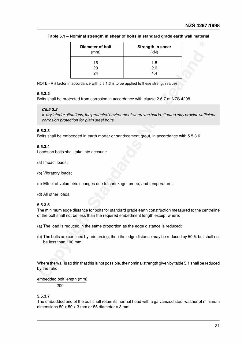
5.5.3.1The design strength in shear of bolts embedded in earth shall be limited to the values given in table 5.1multiplied by the strength reduction factor given by 5.3.1.3.
C5.5.3.1
established by computation, testing, or a combination of these two methods. Such methods areoutside the scope of this Standard.
Designers wishing to utilize higher values than in table 5.1 are referred to the paper CommercialEngineered Aggregate Construction by Oliver and Whybrid (Innovation and Economics in BuildingConference, Brisbane, Australia 23-24 September 1991). That document gives working loads forhigh quality rammed earth.
Copy
right
Sta
ndar
ds N
ew Z
ealan
d *
NZS 4297:1998
31
Table 5.1 – Nominal strength in shear of bolts in standard grade earth wall material
Diameter of bolt Strength in shear(mm) (kN)
16 1.820 2.624 4.4
NOTE - A φ factor in accordance with 5.3.1.3 is to be applied to these strength values.
5.5.3.2Bolts shall be protected from corrosion in accordance with clause 2.6.7 of NZS 4298.
C5.5.3.2In dry interior situations, the protected environment where the bolt is situated may provide sufficientcorrosion protection for plain steel bolts.
5.5.3.3Bolts shall be embedded in earth mortar or sand/cement grout, in accordance with 5.5.3.6.
5.5.3.4Loads on bolts shall take into account:
(a) Impact loads;
(b) Vibratory loads;
(c) Effect of volumetric changes due to shrinkage, creep, and temperature;
(d) All other loads.
5.5.3.5The minimum edge distance for bolts for standard grade earth construction measured to the centrelineof the bolt shall not be less than the required embedment length except where:
(a) The load is reduced in the same proportion as the edge distance is reduced;
(b) The bolts are confined by reinforcing, then the edge distance may be reduced by 50 % but shall notbe less than 100 mm.
Where the wall is so thin that this is not possible, the nominal strength given by table 5.1 shall be reducedby the ratio
embedded bolt length (mm)
200
5.5.3.7The embedded end of the bolt shall retain its normal head with a galvanized steel washer of minimumdimensions 50 x 50 x 3 mm or 55 diameter x 3 mm.
Copy
right
Sta
ndar
ds N
ew Z
ealan
d *
32
NZS 4297:1998
6 FLEXURE WITH OR WITHOUT AXIAL LOAD
6.1 Notation
Ab area of earth cross section
a1 distance from the end of the wall or pier to the nearest end of the bearing area
Ade effective area of dispersion of the concentrated load in the member at mid height
Ads bearing or dispersion area of the concentrated load
As area of tensile reinforcement
av coefficient for assessing slenderness ratio
e eccentricity of vertical force
fe compressive strength of earth wall construction
fet flexural tensile strength of earth
fy lower characteristic yield strength of reinforcement
h height of member
k reduction factor for slenderness and eccentricity given in table 6.1
kb concentrated bearing factor
L clear length of the wall or pier
Le dispersion zone length
Mch design flexural strength of the wall
M* design bending moment acting on the cross section of a member, determined from loadscomplying with NZS 4203
M*dh design horizontal flexural bending moment on wall
Mn nominal flexural strength of a section
N* design axial load at the ultimate limit state acting on a section determined from NZS 4203
No
S r slenderness ratio
t thickness or depth of wall perpendicular to the principal axis under consideration
tw overall thickness of a wall or isolated pier, taking into account any joint raking which isdeeper than 3 mm
Zu the lateral section modulus of the earth wall based on the gross cross section
µ structural ductility factor as defined in NZS 4203
φ capacity reduction factor
Copy
right
Sta
ndar
ds N
ew Z
ealan
d *
NZS 4297:1998
33
6.2 Scope
6.2.1 GeneralThe provisions of this section shall apply to the design of members for flexure with or without axial load.
6.2.1.1The following values of the structural ductility factor, µ , shall apply for earthquake loading design toNZS 4203. The structural ductility factor, µ, shall be taken as 2.0 for limited ductility reinforced earth, andexcept for cinva brick walls where a value of 1.25 shall be used. For elastically responding reinforcedearth and unreinforced earth, µ , shall be taken as 1.0.
6.2.2 FlexureMembers subjected primarily to flexure shall be designed as beams, if reinforced or to the provisions of6.4 if unreinforced.
6.2.3 Compression
6.2.3.1A member which is subjected to a design axial load, N *, in excess of 0.5 feAb shall be designed to havethe total axial load carried by a core of timber, reinforced concrete or steel.
6.2.3.2When the design axial load on the member cross section, N*, is less than 0.5 feAb , then the membershall be designed as a wall or column.
6.2.3.3Unreinforced earth in flexure with or without compression shall be designed in accordance with 6.4.
6.2.3.4Due account shall be taken of combined tension and wall flexure by the methods of this section andAppendix B.
C6.2.3.4This may occur in high wind load situations.
6.2.4 UpliftAccount shall be taken of uplift by the methods of this section and Appendix B. Account shall be takenof the lowering of wall bending strength due to the effective reduction of gravity axial loads because ofwind uplift. The tensile strength of the wall material shall be assumed to be zero.
C6.2.4
uplift. Any connection to the top of the wall needs to be embedded either full depth to the foundationor to a depth such that the self weight of the wall material attached to the connector is greater thanthe design uplift force. The effects of reduced axial compressive load on wall strength is consideredin the methods of Appendix B.
Copy
right
Sta
ndar
ds N
ew Z
ealan
d *
34
NZS 4297:1998
6.3 General principles and requirements
6.3.1 Structural end of an earth memberThe structural end of an earth wall or column supporting vertical loads shall be the vertical surface in themember across which longitudinal shear cannot be transferred, and shall include:
(a) The actual end or vertical face of the member;
(b) A control joint in the member; and
(c) A vertical mortar joint in earth construction (other than perpend joints in normal overlapping bond).
6.3.2 Column construction
6.3.2.1Minimum column dimensions shall be 250 mm square if reinforced, 580 mm square if unreinforced. Themaximum slenderness ratio of a column shall be as stated in 4.6.2.
6.3.2.2Columns shall be constructed so that any vertical flue shall have a minimum clear dimension of 60 mmand a minimum area of 9000 mm2.
6.3.2.3A column flue containing 4 bars shall have minimum clear flue dimensions of 150 mm x 150 mm.
6.3.3 General design assumptions
6.3.3.1Strength design of members for flexure with or without axial loads shall be based on 6.4 if unreinforced,and on rational assumptions given in 6.3.3.2 and on satisfaction of applicable conditions of equilibrium,if reinforced.
6.3.3.2The relationship between earth compressive stress distribution and earth strain shall be consideredsatisfied at an extreme fibre compression stress of fe with a triangular or trapezoidal earth stressdistribution.
C6.3.3.2The relationship between earth wall compressive stress and strain may be assumed to berectangular, trapezoidal, parabolic or any other shape that results in prediction of strength in
Earth walls and columns are often designed on the basis of ultimate strength reinforced concretetheory where M* ≤ φ Mn and Mn = Asfy jd where jd is a proportion of d, the distance from theextreme compression fibre to the centroid of the tension reinforcement.
6.3.4 Longitudinal reinforcement in flexural membersThe failure mode in bending is to be a tension initiated failure.
C6.3.4It is recommended that the tensile strength of reinforcement should be no greater than 75 % of theavailable flexural compressive strength of the section.

Copy
right
Sta
ndar
ds N
ew Z
ealan
d *
NZS 4297:1998
35
6.3.5 Compression reinforcement in membersCompression bar reinforcement shall not be relied upon to enhance the strength of earth members.
6.3.6 Distribution of flexural reinforcementThe flexural tension bar reinforcement shall be evenly distributed within the flexural tension zones of amember cross section.
C6.3.6This clause prescribes the distribution of flexural reinforcement to control flexural cracking inflexural members.
6.3.7 Longitudinal reinforcement in columns
6.3.7.1The diameter of longitudinal reinforcement used in a column shall not be greater than 16 mm.
6.3.7.2The minimum longitudinal reinforcement for a column shall be 1 bar of 12 mm diameter.
6.4 Unreinforced earth
6.4.1 GeneralUnreinforced earth shall include all forms of earth construction such as rammed earth, adobe, pouredearth, pressed brick, whether stabilized or unstabilized.
C6.4.1Although the methods of this clause have been adopted from AS 3700 unreinforced masonrysection and strictly speaking apply to brick constructions only, they are also (conservatively)specified for rammed earth as little is known about the tensile continuity between one rammed earthlayer and the next.
6.4.2 Basis of designEach unreinforced earth member shall be designed to comply with 6.4.3 to 6.4.5, taking into account thestrength of the material and the further provisions in 7.3.1 as applicable for the relevant type of member.
6.4.3 Design for compressive forces and vertical bending
6.4.3.1 GeneralUnreinforced earth members resisting compressive forces, with or without simultaneously actingbending moments, shall be designed to comply with 6.4.3.2. Design for concentrated loads on membersshall comply with 6.4.3.3, and design for lightly loaded members under the action of transient
upon the following factors:
(a) Slenderness;
(b) Effective eccentricity of loading at each end;
(c) Characteristic compressive strength of the earth;
(d) Cross-sectional area of the earth.
In a wall or isolated pier subject to compression and bending, the vertical and bending forces shall becombined at top and bottom of the member by regarding the vertical force as acting at statically
Copy
right
Sta
ndar
ds N
ew Z
ealan
d *
36
NZS 4297:1998
equivalent effective eccentricities, e, at each end. In this calculation, the most unfavourable dispositionof live loads shall be considered. The load combination shall be such that under the worst loadingconditions, the equivalent effective eccentricity at any point does not exceed tw /6.
C6.4.3.1Torsion due to earthquake forces should be minimized in seismic areas by having the combinedcentre of mass of all the walls in plan close to the centre of resistance.
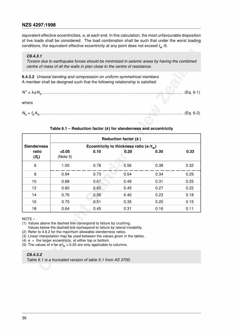
6.4.3.2 Uniaxial bending and compression on uniform symmetrical membersA member shall be designed such that the following relationship is satisfied:
N * ≤ kφNo ............................................................................................................................................................... (Eq. 6-1)
where
No = feAb ................................................................................................................................................................. (Eq. 6-2)
Table 6.1 – Reduction factor (k ) for slenderness and eccentricity
Reduction factor (k )
Slenderness Eccentricity to thickness ratio (e /tw) ratio ≤0.05 0.10 0.20 0.30 0.33 (Sr) (Note 5)
6 1.00 0.78 0.56 0.38 0.32
8 0.94 0.73 0.54 0.34 0.29
10 0.88 0.67 0.49 0.31 0.25
12 0.82 0.62 0.45 0.27 0.22
14 0.76 0.56 0.40 0.23 0.18
16 0.70 0.51 0.35 0.20 0.15
18 0.64 0.45 0.31 0.16 0.11
NOTE –(1) Values above the dashed line correspond to failure by crushing.
Values below the dashed line correspond to failure by lateral instability.(2) Refer to 4.6.2 for the maximum allowable slenderness ratios.(3) Linear interpolation may be used between the values given in the tables.(4) e = the larger eccentricity, at either top or bottom.(5) The values of k for e/tw = 0.05 are only applicable to columns.
C6.4.3.2Table 6.1 is a truncated version of table 5.1 from AS 3700.
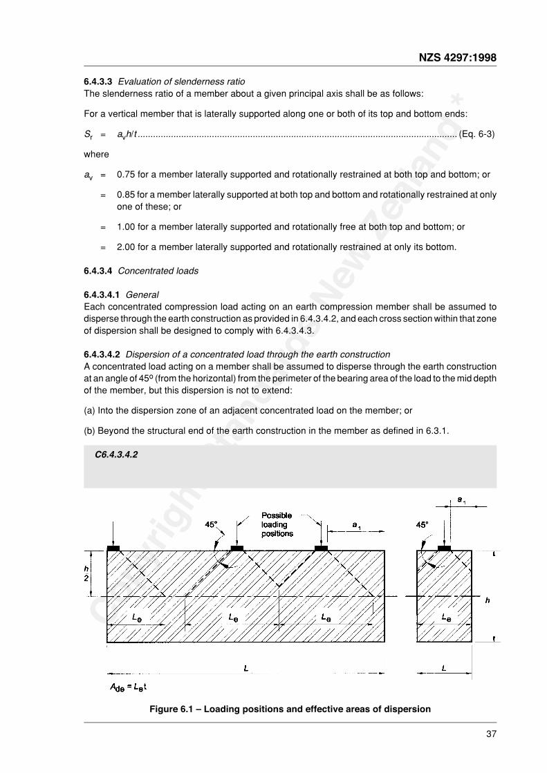
Copy
right
Sta
ndar
ds N
ew Z
ealan
d *
NZS 4297:1998
37
6.4.3.3 Evaluation of slenderness ratioThe slenderness ratio of a member about a given principal axis shall be as follows:
For a vertical member that is laterally supported along one or both of its top and bottom ends:
Sr = avh/t ............................................................................................................................. (Eq. 6-3)
where
av = 0.75 for a member laterally supported and rotationally restrained at both top and bottom; or
= 0.85 for a member laterally supported at both top and bottom and rotationally restrained at onlyone of these; or
= 1.00 for a member laterally supported and rotationally free at both top and bottom; or
= 2.00 for a member laterally supported and rotationally restrained at only its bottom.
6.4.3.4 Concentrated loads
6.4.3.4.1 GeneralEach concentrated compression load acting on an earth compression member shall be assumed todisperse through the earth construction as provided in 6.4.3.4.2, and each cross section within that zoneof dispersion shall be designed to comply with 6.4.3.4.3.
6.4.3.4.2 Dispersion of a concentrated load through the earth constructionA concentrated load acting on a member shall be assumed to disperse through the earth constructionat an angle of 45o (from the horizontal) from the perimeter of the bearing area of the load to the mid depthof the member, but this dispersion is not to extend:
(a) Into the dispersion zone of an adjacent concentrated load on the member; or
(b) Beyond the structural end of the earth construction in the member as defined in 6.3.1.
C6.4.3.4.2
Figure 6.1 – Loading positions and effective areas of dispersion
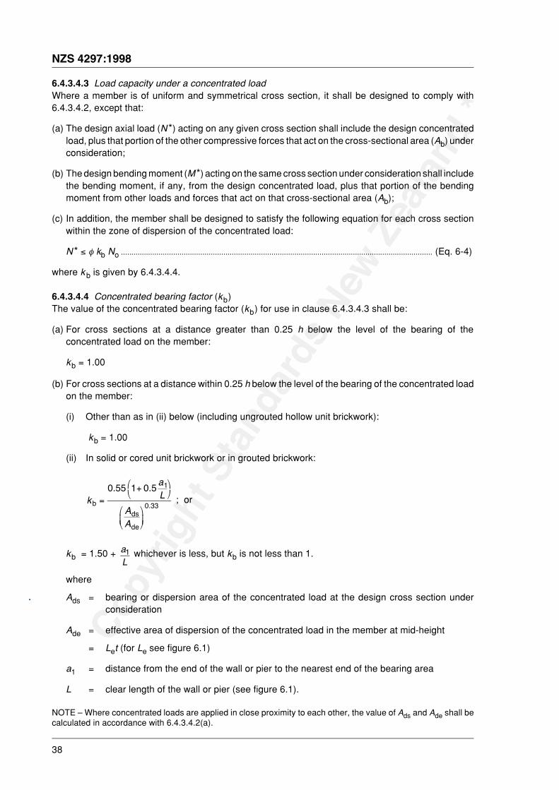
Copy
right
Sta
ndar
ds N
ew Z
ealan
d *
38
NZS 4297:1998
6.4.3.4.3 Load capacity under a concentrated loadWhere a member is of uniform and symmetrical cross section, it shall be designed to comply with6.4.3.4.2, except that:
(a) The design axial load (N *) acting on any given cross section shall include the design concentratedload, plus that portion of the other compressive forces that act on the cross-sectional area (Ab) underconsideration;
(b) The design bending moment (M*) acting on the same cross section under consideration shall includethe bending moment, if any, from the design concentrated load, plus that portion of the bendingmoment from other loads and forces that act on that cross-sectional area (Ab);
(c) In addition, the member shall be designed to satisfy the following equation for each cross sectionwithin the zone of dispersion of the concentrated load:
N * ≤ φ kb No ..................................................................................................................................................... (Eq. 6-4)
where kb is given by 6.4.3.4.4.
6.4.3.4.4 Concentrated bearing factor (kb)The value of the concentrated bearing factor (kb) for use in clause 6.4.3.4.3 shall be:
(a) For cross sections at a distance greater than 0.25 h below the level of the bearing of theconcentrated load on the member:
kb = 1.00
(b) For cross sections at a distance within 0.25 h below the level of the bearing of the concentrated loadon the member:
(i) Other than as in (ii) below (including ungrouted hollow unit brickwork):
kb = 1.00
(ii) In solid or cored unit brickwork or in grouted brickwork:
k
aL
AA
bdsde
.
. .=
+'(
)*
'
(+
)
*,
0 55 1 0 5 1
0 33; or
kb = 1.50 + aL1 whichever is less, but kb is not less than 1.
where
Ads = bearing or dispersion area of the concentrated load at the design cross section underconsideration
Ade = effective area of dispersion of the concentrated load in the member at mid-height
= Let (for Le see figure 6.1)
a1 = distance from the end of the wall or pier to the nearest end of the bearing area
L = clear length of the wall or pier (see figure 6.1).
NOTE – Where concentrated loads are applied in close proximity to each other, the value of Ads and Ade shall becalculated in accordance with 6.4.3.4.2(a).
.

Copy
right
Sta
ndar
ds N
ew Z
ealan
d *
NZS 4297:1998
39
6.4.4 Design for horizontal bending from transient out-of-plane forces
6.4.4.1 GeneralThe design of an unreinforced earth wall, or portion thereof, to withstand horizontal bending fromout-of-plane wind loads, earthquake loads or similar forces of a short-term transient nature, shall complywith 6.4.4.2 or 6.4.5, provided that :
(a) For earth brick walls, the wall has all perpends completely filled;
(b) For pressed earth brick or adobe, the wall, or that part being designed for horizontal bending, hasat least 4 contiguous courses of earth bricks acting together in horizontal bending.
6.4.4.2 Horizontal bending with tension stresses permittedA wall complying with the requirements of 6.4.4.1 shall be proportioned so that the following relationshipis satisfied under each combination of simultaneously acting design horizontal bending moment (M*dh):
M*dh ≤ Mch .............................................................................................................................................................. (Eq. 6-5)
where
Mch = 0.40 φ fet Zu for earth brick walls, or ............................................................................ (Eq. 6.6)
Mch = φ fet Zu for rammed or poured earth walls ................................................................... (Eq. 6.7)
C6.4.4.2The factor of 0.40 allows for bricks laid in overlapping bond which, conservatively, have 40 % ofthe wall height available to resist horizontal moments when the bending strength of the mortar isignored.
6.4.5 Out of plane strength for vertical bendingThe lateral out-of-plane (face) load strength of unreinforced earth walls spanning vertically shall becalculated using the virtual work propped cantilever strength analysis methods of Appendix B. P- deltaseismic effects shall be considered. Out of plane action can be maintained only if individual bricks arerestrained from slipping or rotating.
C6.4.5A virtual work strength analysis method is outlined in the paper by YTTRUP, P. Strength of earthmasonry (adobe) walls subjected to lateral wind forces. Proceedings, 7th International BrickMasonry Conference, Melbourne, February 1985.
6.5.1.1Columns shall be designed for the most unfavourable combination of design moment, M *, anddesign axial load, N *.
6.5.1.2Unreinforced columns shall be designed as short walls to the method of 6.4.3.2.
6.5.1.3If e/tw exceeds 0.2 then flexure about both axes shall be considered together. The combined actionshall not put any part of the section into tension.
Copy
right
Sta
ndar
ds N
ew Z
ealan
d *
40
NZS 4297:1998
6.5.2 Composite columnsWhere other material column sections are built into earth walls, or columns, the strength of the earth shallnot be included in the calculation of the strength of the column section.
6.6 Principles and requirements additional to 6.3 for members designed for seismic loading
6.6.1 Strength calculationsColumns of earth shall not be used to provide main structure lateral load restraint unless they containother material sections which can resist the whole of the lateral load.
7 SHEAR
7.1 Notation
Ab area of earth cross section
As area of tensile reinforcement
Asv area of shear reinforcement
d depth of section in the direction of shear
fd compressive stress acting on section under the design loading
fes shear strength of earth
fn total nominal shear stress
fsy lower characteristic yield strength of shear reinforcement
fy lower characteristic yield strength of reinforcement
h height of member
kv shear factor as given in 7.3.1.2
L clear length of the wall or pier
s spacing of shear reinforcement measured perpendicular to direction of shear force
t thickness or depth of wall perpendicular to the axis under consideration
assessed from NZS 4203
Vn nominal shear strength of the section (kN)
δ coefficient of variation
µ structural ductility factor
φ capacity reduction factor
it bu
t not
mor
e th
an 1
0% o
f the
doc
umen
ts s
ubsc
ribed
to m
ay b
e he
ld in
prin
ted
form
at
Copy
right
Sta
ndar
ds N
ew Z
ealan
d *
NZS 4297:1998
41
7.2 Scope
7.2.1Provisions of this section apply to design of earth walls for shear and torsion with flexure and with orwithout axial load. Design of earth walls for shear and torsion shall be in accordance with establishedprinciples for reinforced concrete, as set out in NZS 3101, section 9 modified by the requirements of thissection. Where no specific requirements are given in this section, the appropriate requirements ofNZS 3101 section 9 shall apply.
7.3 General principles and requirements
7.3.1 Unreinforced earth
7.3.1.1 Shear capacityThe design of an unreinforced earth wall subject to shear forces, with or without simultaneouscompressive forces acting across the shear plane, shall be such that the following relationship issatisfied under each combination of simultaneously acting design shear force, V*, and (minimum)compressive stress (fd) acting at the cross section under consideration:
V * ≤ φ [fesAb + kvfdAb ] .......................................................................................................... (Eq. 7-1)
or
V * ≤ 5φfesAb ........................................................................................................................... (Eq. 7-2)
whichever is less.
Limited ductility seismic design principles shall not be applied to unreinforced earth.
C7.3.1.1The factor of 5 term in equation 7-2 places an upper limit on the influence of vertical load. Verticalreinforcement pretension may be taken into account in calculating fd provided the pretension ismaintained after shrinkage has taken place.
7.3.1.2 Shear factor (kv)The value of kv for use in 7.3.1.1 shall be:
(a) At membrane-type damp-proof courses, flashings, and similar locations having low friction resistance:
kv
kv = 0.30. ............................................................................................................................ (Eq. 7-4)
C7.3.1.2Testing may be used to establish values for kv different to those given by 7.3.1.2. Such testing isoutside the scope of this Standard. The value of kv from equation 7.4 necessitates reinforcementpenetrating damp proof membranes to ensure shear continuity.
7.3.1.3 Development of longitudinal shear strengthWhere it is necessary to transfer shear forces across wall intersections and vertical mortar joints in earthbrick construction, the bonding or tying across the shear plane shall be an overlapping bond.
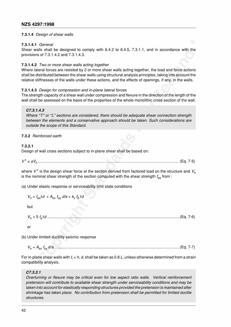
Copy
right
Sta
ndar
ds N
ew Z
ealan
d *
42
NZS 4297:1998
7.3.1.4 Design of shear walls
7.3.1.4.1 GeneralShear walls shall be designed to comply with 6.4.2 to 6.4.5, 7.3.1.1, and in accordance with theprovisions of 7.3.1.4.2 and 7.3.1.4.3.
7.3.1.4.2 Two or more shear walls acting togetherWhere lateral forces are resisted by 2 or more shear walls acting together, the load and force actionsshall be distributed between the shear walls using structural analysis principles, taking into account therelative stiffnesses of the walls under these actions, and the effects of openings, if any, in the walls.
7.3.1.4.3 Design for compression and in-plane lateral forcesThe strength capacity of a shear wall under compression and flexure in the direction of the length of thewall shall be assessed on the basis of the properties of the whole monolithic cross section of the wall.
C7.3.1.4.3Where “T” or “L” sections are considered, there should be adequate shear connection strengthbetween the elements and a conservative approach should be taken. Such considerations areoutside the scope of this Standard.
7.3.2 Reinforced earth
7.3.2.1Design of wall cross sections subject to in-plane shear shall be based on:
V * ≤ φVn ................................................................................................................................................................... (Eq. 7-5)
where V * is the design shear force at the section derived from factored load on the structure and Vnis the nominal shear strength of the section computed with the shear strength fes from :
(a) Under elastic response or serviceability limit state conditions
Vn = fest d + Asv fsy d/s + kv fd t d
but
Vn < 5 fet d .......................................................................................................................... (Eq. 7-6)
or
(b) Under limited ductility seismic response
Vn = Asv fsy d/s ................................................................................................................... (Eq. 7-7)
For in-plane shear walls with L < h, d, shall be taken as 0.8 L, unless otherwise determined from a straincompatibility analysis.
C7.3.2.1Overturning or flexure may be critical even for low aspect ratio walls. Vertical reinforcementpretension will contribute to available shear strength under serviceability conditions and may betaken into account for elastically responding structures provided the pretension is maintained aftershrinkage has taken place. No contribution from pretension shall be permitted for limited ductilestructures.
Copy
right
Sta
ndar
ds N
ew Z
ealan
d *
NZS 4297:1998
43
7.3.2.2For walls with L ≥ h, d shall be taken as equal to L.
7.3.2.3In determining shear strength, Vn, effects of axial tension, including tension from creep and shrinkageand from differential temperature, shall be considered wherever applicable.
7.3.3 Shear reinforcement details
7.3.3.1Shear reinforcement shall consist of:
(a) Steel of either normal or high strength (either deformed or plain) except as provided by 8.3.9; or
(b) Welded wire fabric within the plane of the member with wires cut to form “ladders” or “fish bones”;or
(c) Polypropylene biaxial geogrid or similar with square or rectangular apertures. The quality controlstrength of the geogrid shall be determined in accordance with BS EN ISO 10319. The geogrid tobe cut into strips to form ladders of reinforcement.
C7.3.3.1Other types of reinforcing may be used subject to rational engineering analysis but are outside thescope of this Standard.
Examples of shear reinforcement are shown in figure 5.5 of NZS 4299.
7.3.3.2Bars or wires used as shear reinforcement shall be anchored at both ends according to 8.3.4.5 to developthe lower characteristic yield strength of reinforcement.
C7.3.3.2Some practitioners also specify “sensible minimums” horizontal reinforcing at every fourth courseor every 600 mm whichever is least whether the design calculations require them or not.
7.3.3.3Shear reinforcement shall be evenly distributed through the height of the wall.
7.3.3.4Polypropylene geogrids used as shear reinforcement shall be anchored to vertical reinforcing at each
7.4 Principles and requirements additional to 7.3 for members designed for seismic loads
7.4.1 Shear strength
7.4.1.1The provisions of 7.4 shall apply to members whose required nominal shear strength under seismicloading corresponds to a structural ductility factor µ of ≤ 2.0. For members whose required ideal shearstrength under seismic loading corresponds to 2.0 ≥ µ ≥ 1.25, provisions shall be obtained by linearinterpolation between the requirements of 7.3 and 7.4.

Copy
right
Sta
ndar
ds N
ew Z
ealan
d *
44
NZS 4297:1998
7.4.1.2The design shear force in members subjected primarily to flexure shall be determined from considerationsof static transverse forces on the member, with the flexural overstrength being developed at the mostprobable location of critical sections within the member or in adjacent members, together with the gravityload at the appropriate load factor.
7.4.1.3Shear strength provided in limited ductile walls shall have a suitable margin over required in-planeflexural strengths. The overstrength of the wall due to in-plane flexure shall be calculated to be aminimum of 1.25/φ. Where the limited ductile wall is less than 1.4 m long the influence on flexuraloverstrength shall also be considered for a soil compression overstrength factor of a minimum of 4unless the overstrength factor is determined from knowledge of the earth strength coefficient ofvariation. Such determination is outside the scope of this Standard.
C7.4.1.3For limited ductile wall design a flexural mode of failure is required. This clause includes anallowance of 1.25 As fy factor to account for steel overstrength.
In short walls the length of the compression zone is significant in determining the moment capacityand allowance for the earth material overstrength should be made. In variable materials thecalculated value of characteristic strength may sometimes be well below the actual strength.Where the coefficient of variation is 0.2 the given overstrength is 4 based on (population averagecompressive strength) / (5 percentile of sample characteristic strength). For a coefficient of avariation, δ of 0.25 compressive overstrength is about 6, and for δ of 0.35 could be 10 or higher.
7.4.1.4The design shear force in members subjected to combined flexure and axial load shall be determinedfrom considerations of static forces on the member, with the worst likely combination of the maximumlikely end moments, and where appropriate with flexural overstrength being developed at criticalsections.
7.4.1.5Where a structure is designed to perform with limited ductility, then appropriate redistribution of shearloads shall be carried out.
7.4.1.6In applying equation 7-4 to design of cross sections where the shear force is calculated in accordancewith 7.4.1.1 and 7.4.1.2, a capacity reduction factor φ = 1.0 shall be adopted.
7.4.1.7Total nominal shear stress, fn, shall not exceed the maximum grade-dependent values, fes, listed intable 4.1 and 4.5.4.
7.4.2 Shear strength provided by earth
7.4.2.1In all potential plastic hinge regions of columns and walls, for µ = 2.0, the shear stress, fes, shall beassumed to be zero for any seismic load combination.
7.4.2.2For µ ≤ 1.25, the shear strength of the earth may be utilized and horizontal reinforcement is notmandatory.
Copy
right
Sta
ndar
ds N
ew Z
ealan
d *
NZS 4297:1998
45
8 REINFORCEMENT – DETAILS, ANCHORAGE AND DEVELOPMENT
8.1 Notation
d b bar diameter
fy lower characteristic yield strength of reinforcement
8.2 Scope
8.2.1Provisions of section 8 shall apply to detailing of reinforcement, including spacing and cover, and designof anchorage, development and splices.
8.3 General principles and requirements for members designed for seismic loading
8.3.1 Steel reinforcement
8.3.1.1Reinforcing bars shall conform to NZS 3402. Hard drawn mild steel wire shall conform with NZS 3421.
8.3.1.2Reinforcement details shall be in accordance with clause 2.6 of NZS 4298.
8.3.1.3Joint reinforcement, where permitted to be used by this Standard may be fabricated in a form of a latticetruss with two 4 mm diameter mild steel wires connected by a 2 mm diameter lattice welded to them andthe whole assembly hot dipped galvanized after fabrication. A “fish bone” or ladder cut from welded steelmesh reinforcing may be used.
C8.3.1.3Other types of joint reinforcement which satisfy the requirements of this Standard and NZS 4298may be used.
8.3.2 Spacing of reinforcement
8.3.2.1The clear distance between parallel reinforcing bars in a layer shall be not less than the nominal diameterof the bars, nor less than 25 mm.
8.3.2.2
between the individual reinforcing bars or bundles.
Copy
right
Sta
ndar
ds N
ew Z
ealan
d *
46
NZS 4297:1998
8.3.3 Mechanical anchorage
8.3.3.1Anchorage of reinforcing shall be one of:
(a) An anchorage in concrete to NZS 3101;
(b) (i) A maximum 6 mm bar standard hooked 300 mm around a minimum 12 mm bar for adobe;
(ii) Maximum 10 mm bar for rammed earth and pressed brick hooked 300 mm around a minimum12 mm bar.
(c) Anchorage to a timber block or plate such that the provisions of 8.3.3.2 are complied with and thefull tensile strength of the reinforcing bar is able to be developed.
8.3.3.2Earth material in contact with anchorages shall have adequate bearing strength in accordance with6.4.3.4.
8.3.4 Splices in reinforcement – General
8.3.4.1Splices of reinforcement shall be indicated on the design drawings or in specifications. Splicesembedded in earth material (rather than in cement grout filled cores) shall be welded or mechanicallyjoined in accordance with 8.3.4.4.
C8.3.4.1Tests may be used to confirm that the ultimate strength of the bar is developed by lapped spliceshowever such testing is outside the scope of this Standard.
8.3.4.2Except as provided herein, all welding of reinforcing bars shall conform to NZS 4702.
8.3.4.3Welds shall not be made closer than 10 db from bends. Hard drawn steel wire reinforcing shall not bewelded.
C8.3.4.3Bars not conforming to NZS 3402 may be welded provided the welding technique and local controlof conditions shall have been demonstrated by tests to produce welds that have the requiredmechanical and metallurgical properties. Such welds are outside the scope of this Standard.
8.3.4.4Welded splices or mechanical connections satisfying the following conditions, shall be used:
(a) Lap welded splices designed in accordance with NZS 3101; or
(b) Full strength welded splices in which the bars are butt welded to develop in tension the breakingstrength of the bar; or
(c) High strength welded splices in which the bars are butt welded to develop in tension 1.6 fy or thebreaking strength of the bar, whichever is smaller; or
(d) Mechanical connections which are defined as a connection which relies on mechanical interlock withthe bar deformations to develop the connection capacity. A high strength mechanical connection
Copy
right
Sta
ndar
ds N
ew Z
ealan
d *
NZS 4297:1998
47
shall develop in tension or compression, as required, not less than 1.6 fy or the breaking strength ofthe bar, whichever is smaller. When tested in tension or compression as appropriate, the changeof length at a stress of 0.7 fy in the bar, and measured over the full length of the connection systemshall be not more than twice that of an equal length of unspliced bar.
8.3.4.5Shear reinforcing shall be anchored at ends by one of:
(a) Providing a 180o bend with a 300 mm return around another bar; or
(b) Embedment in concrete or grout sufficient to develop the tensile strength of the reinforcement whichhas bearing area to earth which complies with 6.4.3.4.
(c) Anchorage to a timber block or plate in accordance with the requirements of 8.3.3.1(c).
C8.3.4.5Care should be taken to ensure adequate anchorage for shear reinforcement.
The method of (a) above is not recommended for horizontal shear reinforcing greater than 6 mmdiameter.
Mechanical anchorage may be used but the design of such anchorages is outside the scope of thisStandard.
8.3.5 Protection for reinforcementThe minimum cover of earth or grout, whichever is applicable, provided for reinforcing bars shall be asshown in clause 2.6.7 of NZS 4298.
8.3.6 Protection of exposed reinforcing bars and fittingsExposed reinforcing bars, inserts and plates intended for bonding with future extensions shall beprotected from corrosion.
8.3.7 Covers required for fire protectionWhere fire design requires a fire-protection covering greater than the earth protection specified in,clause 2.6.7 of NZS 4298 such greater thickness shall be used.
8.3.8 Wall reinforcementWall reinforcement shall be in accordance with sections 6, 7 and 9.
8.3.9 Deformed/undeformed reinforcementIn rammed earth, to minimize the risk of horizontal cracking caused by “hang-up” on deformations, round
9.1 Notation
µ structural ductility factor
9.2 General principles and requirementsFoundations shall be of reinforced concrete the same width of the earth wall that it supports, or of solid-filled reinforced concrete masonry fired brick or stone masonry. Reinforced concrete masonry shall bethe same width as the wall above, except that a 240 mm wide masonry footing may support a 300 mmwide earth wall. For walls wider than 300 mm reinforced concrete footings shall be used and they shallbe the full width of the wall.
Copy
right
Sta
ndar
ds N
ew Z
ealan
d *
48
NZS 4297:1998
9.2.1Foundations shall be designed using the methods of the New Zealand Building Code VerificationMethod B1/VM4.
C9.2.1Components such as concrete block, ceramic brick or stone masonry to give a fair-finish to the outerexposed above-ground face of the reinforced concrete foundation may be used.
9.3 Loads and reactions
9.3.1 Proportions, loads and depths
9.3.1.1Foundations shall be proportioned to resist the design loads and induced reactions, in accordance withthe appropriate design requirements of this Standard.
9.3.1.2Base area of foundations shall be determined from external forces and moments resulting from factoredloads, transmitted by the foundation to the soil, and soil strengths selected through principles of soilmechanics.
9.3.1.3The foundation system of all structures shall be carried to depths such that adequate bearing is secured.Due allowance shall be made for the effects of seasonal changes of moisture, lateral movement of theground and movements of ground in unstable areas.
9.3.1.4When combinations of deep and shallow foundations are necessary, differential settlement and torsionaleffects shall be considered in the design of foundation members and the provision of control joints.
9.3.1.5Long-term settlements shall not impair the serviceability of the superstructure by cracking or movement.
9.3.2 Construction of foundations
9.3.2.1Concrete shall be ordinary grade or higher as defined in NZS 3109.
9.3.3 Moments in strip foundations
9.3.3.1Reinforcement shall be provided to the top and bottom of strip foundations to resist design loads andshall be not less than 200 mm2 of steel in total. Design shall be in accordance with NZS 3101.
9.3.4 Shear in strip foundations
9.3.4.1Minimum shear reinforcement shall be provided and its spacing shall be at no further apart than 600 mmcentre to centre. Design shall be in accordance with NZS 3101.
Copy
right
Sta
ndar
ds N
ew Z
ealan
d *
NZS 4297:1998
49
9.3.5 Minimum foundation height above finished ground level
9.3.5.1Where finished ground is a paved surface, the top of the foundation (i.e. the base of the earth wall) shallbe no less than 150 mm above the finished paved surface level.
9.3.5.2The height of the foundation (i.e. the base of the earth wall) shall be no less than 225 mm above finishedground where this is soil, loose gravel or other unpaved surface.
C9.3.5.2The purpose of this clause is to prevent moisture damage to the base of earth walls. Compliancewill require careful design consideration and plan detailing of the proposed finished ground typesand heights at all points around the structure.
9.3.5.3The top of the foundation under the earth walls shall be cleaned of any laitance, be roughened to 5 mmamplitude and have 2 coats bituminous sealer applied so as to form a water impermeable layer.
9.4 Principles and requirementsadditional to 9.3 for foundations designed for seismic loading
9.4.1The foundation design shall be in accordance with the provisions of this Standard using the factoredloading specified in NZS 4203, as modified by this Standard.
9.4.2The foundation system shall maintain its ability to support the design gravity loads while maintaining thechosen earthquake energy dissipating mechanism in the structure.
9.4.3All members shall comply with the additional principles and requirements for members designed forseismic loadings as set down in the relevant sections of this Standard. However, flexural members notdesigned for ductile behaviour which have an ideal strength not less than the greatest total seismic loadthat can be transmitted to them from the superstructure, need not comply with these requirements.
9.4.4
Copy
right
Sta
ndar
ds N
ew Z
ealan
d *
50
NZS 4297:1998
APPENDIX AMETHOD FOR DURABILITY DESIGN(Normative)
A1 NOTATION
b eaves width (mm)
h height of wall to eaves (mm)
p annual rainfall (mm)
k1 rainfall factor
k2 wall orientation factor
k3 eaves factor
k4 locality factor
V(z) site wind speed at height z for the direction under consideration at the ultimate limit state (m/s)
A2For a given locality and geometry of wall, the Limiting Erodibility Index (LEI) shall be calculated asfollows:
Limiting Erodibility Index = k1 k2 k3 k4 (rounded down to nearest whole number)
where
k1 = Rainfall factor
=500
3 p V× (z)
k2
k3
= 1 2+
bh
k4 = 1.0 except for wind region I (Northland) as defined by clause 5.4 of NZS 4203
where
k4 = 0.93.
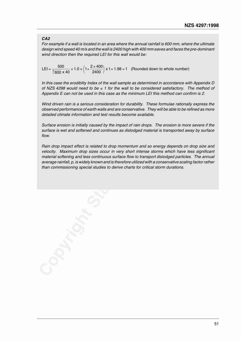
Copy
right
Sta
ndar
ds N
ew Z
ealan
d *
NZS 4297:1998
51
CA2For example if a wall is located in an area where the annual rainfall is 600 mm, where the ultimatedesign wind speed 40 m/s and the wall is 2400 high with 400 mm eaves and faces the pre-dominantwind direction then the required LEI for this wall would be:
LEI . . (Rounded down to whole number)= × × +×'
()*
= =500
6001 0 1 2 400
24001 1 98 13 x 40
x
In this case the erodiblity Index of the wall sample as determined in accordance with Appendix Dof NZS 4298 would need to be ≤ 1 for the wall to be considered satisfactory. The method ofAppendix E can not be used in this case as the minimum LEI this method can confirm is 2.
Wind driven rain is a serious consideration for durability. These formulae rationally express theobserved performance of earth walls and are conservative. They will be able to be refined as moredetailed climate information and test results become available.
Surface erosion is initially caused by the impact of rain drops. The erosion is more severe if thesurface is wet and softened and continues as dislodged material is transported away by surfaceflow.
Rain drop impact effect is related to drop momentum and so energy depends on drop size andvelocity. Maximum drop sizes occur in very short intense storms which have less significantmaterial softening and less continuous surface flow to transport dislodged particles. The annualaverage rainfall, p, is widely known and is therefore utilized with a conservative scaling factor ratherthan commissioning special studies to derive charts for critical storm durations.
Copy
right
Sta
ndar
ds N
ew Z
ealan
d *
52
NZS 4297:1998
APPENDIX BMETHOD FOR DETERMINATION OF SEISMIC RESISTANCEOF UNREINFORCED EARTH WALLS(Normative)
B1 Notationa Width of stress block at ultimate limit state
ae response acceleration to induce wall failure
acr, a1/2, a3/4, au acceleration at cracking, 1/2 cracked, 3/4 cracked and ultimate momentcondition respectively
A1 area under response acceleration versus wall displacement curve
Cpi basic horizontal seismic coefficient for a part at level i from NZS 4203
Ee modulus of elasticity of earth wall material
fe compressive strength of earth wall construction
h height of wall between horizontal restraints
Ι moment of inertia of wall section
kcr initial wall stiffness
Mcr, M1/2, M3/4, Mumoment in wall at cracking, 1/2 cracked, 3/4 cracked and ultimate conditionrespectively
P gravity load per unit length at top of wall
R vertical reaction at crack
t wall thickness
wcr, w1/2, w3/4, wu distributed lateral load required to induce corresponding wall moment
W self weight of wall under investigation
γ density of wall material
Δcr, Δ1/2, Δ3/4, Δu displacement at centre of wall at cracking, 1/2 cracked, 3/4 cracked andultimate conditions
µ structural ductility factor
φ capacity reduction factor
B2 GeneralThis method involves plotting the response acceleration versus wall displacement curve from 4calculated points. The equal energy principle is used to determine the equivalent elastic response
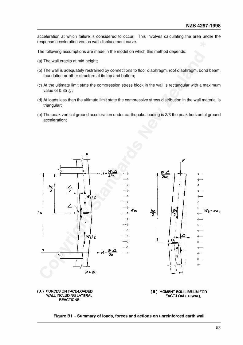
Copy
right
Sta
ndar
ds N
ew Z
ealan
d *
NZS 4297:1998
53
acceleration at which failure is considered to occur. This involves calculating the area under theresponse acceleration versus wall displacement curve.
The following assumptions are made in the model on which this method depends:
(a) The wall cracks at mid height;
(b) The wall is adequately restrained by connections to floor diaphragm, roof diaphragm, bond beam,foundation or other structure at its top and bottom;
(c) At the ultimate limit state the compression stress block in the wall is rectangular with a maximumvalue of 0.85 fe ;
(d) At loads less than the ultimate limit state the compressive stress distribution in the wall material istriangular;
(e) The peak vertical ground acceleration under earthquake loading is 2/3 the peak horizontal groundacceleration;
Figure B1 – Summary of loads, forces and actions on unreinforced earth wall
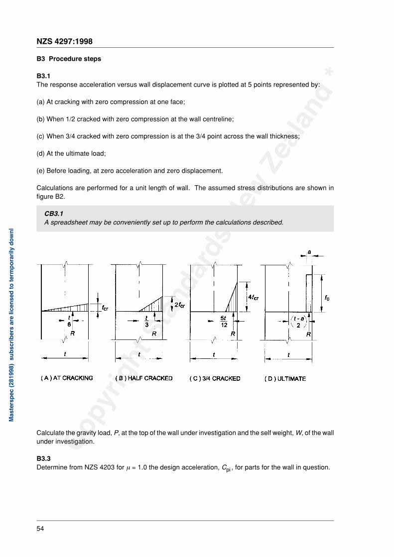
Copy
right
Sta
ndar
ds N
ew Z
ealan
d *
54
NZS 4297:1998
B3 Procedure steps
B3.1The response acceleration versus wall displacement curve is plotted at 5 points represented by:
(a) At cracking with zero compression at one face;
(b) When 1/2 cracked with zero compression at the wall centreline;
(c) When 3/4 cracked with zero compression is at the 3/4 point across the wall thickness;
(d) At the ultimate load;
(e) Before loading, at zero acceleration and zero displacement.
Calculations are performed for a unit length of wall. The assumed stress distributions are shown infigure B2.
CB3.1A spreadsheet may be conveniently set up to perform the calculations described.
Calculate the gravity load, P, at the top of the wall under investigation and the self weight, W, of the wallunder investigation.
B3.3Determine from NZS 4203 for µ = 1.0 the design acceleration, Cpi , for parts for the wall in question.
Mas
ters
pec
(281
998)
subs
crib
ers
are
licen
sed
tote
rmpo
raril
ydo
wnl
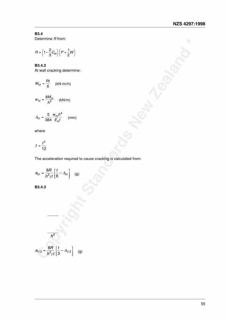
Copy
right
Sta
ndar
ds N
ew Z
ealan
d *
NZS 4297:1998
55
B3.4Determine R from:
R C P W= '(
)*
+'(
)*
1 23
12
– pi
B3.4.2At wall cracking determine:
M Rtcr =
6 (kN-m/m)
w Mhcr
cr=8
2 (kN/m)
ΔΙcr
cr
e=
5384
4w hE (mm)
where
Ι =t 3
12
The acceleration required to cause cracking is calculated from:
a Rh t
tcr cr–= /
01234
862γ
Δ (g)
B3.4.3
2h
a Rh t
t1 2 2 1 2
83/ /–= /01
234γ
Δ (g)

Copy
right
Sta
ndar
ds N
ew Z
ealan
d *
56
NZS 4297:1998
B3.4.4At wall 3/4 cracked determine:
M3/4 = 2.5 Mcr (kN-m/m)
w Mh3 4 2
20/
cr= (kN/m)
Δ3/4 = 16Δcr (mm)
a Rh t
t3 4 2 3 48 5
12/ /–= /01
234γ
Δ (g)
B3.4.5A wall ultimate moment:
M R t au –= '
()*2 2 (kN-m/m)
where
a Rf
=0 85. e
(kN/m)
wu = 0
Δut a
=2 2
– (mm)
au = 0
B3.5Plot response acceleration, a, (y-axis) against wall displacement, Δ (x-axis) including (0,0).
B3.6Measure the area under the curve plotted = A1 (mm x g units)
B3.7Determine response acceleration to induce wall failure, ae, from:
a k Ae cr= φ 2 1 (g)
where
initial wall stiffness
kcr = acr /Δcr
B4 Ultimate strength criterionThe wall shall be designed such that:
ae > Cpi
CB4Reference: New Zealand National Society for Earthquake Engineering 4 June 1996. TheAssessment and Improvement of the Structural Performance of Earthquake Risk Buildings (Draftfor general release for comment for the Building Industry Authority).
i

Copy
right
Sta
ndar
ds N
ew Z
ealan
d *
© 1998 STANDARDS COUNCIL
First published: 2 October 1998Reprinted: 30 March 2001
The following SNZ references relate to this Standard:
Project No. BD/083-0010Draft for comment No. DZ 4297Printing code: 300-2001/7012/17635Typeset by: Standards New ZealandPrinted by: Anco Print Ltd
NZS 4297:1998

NZS 4297:1998
NZS 4297:1998