MOLTEN SALT REACTOR - Lehrstuhl f¼r Nukleartechnik: Startseite
Headline Electrochemistry, 86(2), 21–28 (2018)
Novel Molten Salt Electrochemical Processes for Industrial ApplicationsYasuhiko ITO,* Tokujiro NISHIKIORI, and Hiroyuki TSUJIMURA
I’MSEP Co., Ltd., D-egg, Kodo-1, Jizodani, Kyotanabe, Kyoto 610-0332, Japan
*Corresponding author: [email protected]
ABSTRACTVarious novel technological seeds of molten salt electrochemical processes (MSEPs) were created by the authorsand their collaborators, which are currently under development for industrial applications. Among these, wedescribe four key processes: (1) electrochemical formation of carbon film, (2) plasma-induced dischargeelectrolysis for producing nanoparticles, (3) recycling crucial metals using a “bifunctional electrode”, and (4)electrolytic synthesis of ammonia from water and nitrogen under atmospheric pressure. Furthermore, we discusstheir possible industrial applications in the fields of energy, the environment, resources, and materials with a viewto the future low-carbon society.
© The Electrochemical Society of Japan, All rights reserved.
Keywords : Molten Salt Electrochemical Process, Carbon Film, Metal Nanoparticle and Recycling, AmmoniaSynthesis
1. Introduction
The physicochemical characteristics of molten salts offerconsiderable advantages in creating novel molten salt electrochem-ical processes (MSEPs).1,2 Consequently, we are currently workingto develop novel MSEPs that can be used to invent new industrialfields. Among these, here we focus on the following four processesand describe them in detail.
2. Electrochemical Formation of Various Types of Carbon
The electrochemical formation of carbon can be achieved eitherby anodic oxidation of a C2
2¹ ion or by cathodic reduction of aCO3
2¹ ion in a molten salt system.
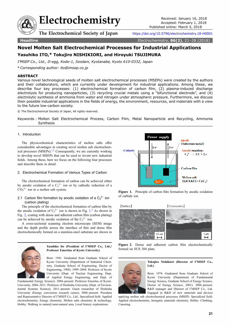
2.1 Carbon film formation by anodic oxidation of a C22− ion
(carbon plating)The principle of the electrochemical formation of carbon film by
the anodic oxidation of C22¹ ion is shown in Fig. 1.3 As shown in
Fig. 2, coating with dense and adherent carbon film (carbon plating)can be achieved by anodic oxidation of the C2
2¹ ion.A cross-sectional scanning electron microscope (SEM) image
and the depth profile across the interface of thin and dense filmelectrochemically formed on a stainless-steel substrate are shown in
Yasuhiko Ito (President of I’MSEP Co., Ltd./Professor Emeritus of Kyoto University)
Born: 1941. Graduated from Graduate School ofKyoto University (Department of Industrial Chem-istry, Graduate School of Engineering, Doctor ofEngineering, 1968). 1989–2004: Professor of KyotoUniversity (Dept. of Nuclear Engineering, Dept.of Applied Energy Engineering, and Dept. of
Fundamental Energy Science). 2004–present: Professor Emeritus of Kyoto.University, 2004–2011: Professor of Doshisha University (Dept. of Environ-mental Systems Science), 2011–present: Guest researcher of DoshishaUniversity (Energy conversion research center), 2006–present: Presidentand Representative Director of I’MSEP Co., Ltd., Specialized field: Appliedelectrochemistry, Energy chemistry, Molten salts chemistry & technology,Hobby: Walking in natural/semi-natural area, Local history explorations.
Tokujiro Nishikiori (Director of I’MSEP Co.,Ltd.)
Born: 1974. Graduated from Graduate School ofKyoto University (Department of FundamentalEnergy Science, Graduate School of Energy Science,Doctor of Energy Science, 2001). 2006–present:R&D manager and Director of I’MSEP Co., Ltd.Engaged in R&D of new materials and devices
applying molten salt electrochemical processes (MSEP). Specialized field:Applied electrochemistry, Inorganic materials chemistry, Hobby: Climbing,Canoeing.
Figure 1. Principle of carbon film formation by anodic oxidationof carbide ion.
Figure 2. Dense and adherent carbon film electrochemicallyformed on SUS 304 plate.
Electrochemistry Received: January 16, 2018Accepted: February 1, 2018
Published online: March 5, 2018
The Electrochemical Society of Japan https://doi.org/10.5796/electrochemistry.18-H0001
21

Fig. 3. Various properties of the carbon plated metal substrate aresummarized in Table 1.
It should be emphasized that the morphology and characteristicnature of the obtained film is strongly influenced by the pre-treatment and electrolytic conditions,4 although they are notpresented here explicitly. The electrical contact resistance of thecarbon-coated metal plate showed very promising measurementresults, and thus the obtained carbon-coated metal actually hasadvantageous features for a fuel cell separator and a current collectorin an Li-ion secondary battery/capacitor. The effect of carbonplating on the performance of a capacitor after a floating test (60°C,3.1V, 200 h) is shown in Table 2.
Currently, we produce large (A4-size) carbon coated metal platesusing the bench-scale carbon-plating apparatus shown in Fig. 4.Moreover, since we can even coat the surface of a screw thread witha thin and dense adherent carbon film, as well as the inside of aporous body (Figs. 5(a), (b)), this process can be used to producecorrosion-resistant fastening components (bolts and nuts) andmetallic porous bodies.2,5
The bench-scale barrel-type plating apparatus for carbon platingof fastening components shown in Fig. 6 was operated success-fully,2 although some problems must still be solved to obtain high-quality products. Furthermore, this carbon-plating technology canalso be applied to materials for use in various machine industries.
2.2 Carbon electrodeposition by cathodic reduction of a CO32−
ionOn the other hand, various types of carbon can be obtained by
cathodic reduction of a CO32¹ ion. Examples of deposited carbon
are shown in Fig. 7. Micro-porous structured carbon film isadvantageous for application to capacitors, super-capacitors, andbatteries.2,3,5 The principle of carbon deposition by cathodicreduction of a CO3
2¹ ion is shown in Fig. 8,3 taking the formationof carbon film as an example.
Table 1. Various properties of the carbon plated on the surface ofmetal substrate.
Wearresistance
*No change after sand eraser test(rubbed 300 times go- and returns with 9.8N)
Corrosionresistance
*No corrosion against aqueous FeCl3 soln.*Higher corrosion resistance than that of bare stainlesssteel against anodic polarization in a sulfuric acidsolution.
Contactelectricalresistance
*1 order less resistance than that of bare stainless steel.*No resistance change before and after corrosion test.
Slidingproperties
*Very smooth (by SEM observation).*Friction factor is less than 0.2.
Adhesiveproperties
*Critical delamination load of scratch test: 33–36N.In case of DLC film obtained by PVD (1mm thick,high speed steel, no inter mediate layer): 5–10N.
SurfaceHardness
*Hardness: 5.6–6.6GPa, Young’s modulus:70–72GPa.
Table 2. Effect of carbon plating on the performance of acapacitor.
Capacitor Compornents
Electrode size ] 16mm
Active mass Active carbon
Conduction supporting agent Acetylene black
Binder SBR, CMC
Electrolyte 1M Et4NB4PC
Separator PE resin film
Cell specificelectrostatic
capacitance/F g¹1Capacity
maintenancefactor/%
Before test After test
Carbon-plated Al foil 19 15 83
[for comparison]Etched Al foil
22 13 58
[for comparison]Carbon-coated Al foil
23 3 13
Line of analysis
400 nm
Carbonfilm
SUS304Substrate
Protective coatC
0 500 1000 1500 2000
Inte
nsity
/ a.
u.
Depth / nm
Figure 3. Cross-sectional SEM image and depth profile across theinterface of the carbon film electrochemically formed on stainlesssteel (SUS304).
Hiroyuki Tsujimura (Senior research Scientist/Project Promotion manager of I’MSEP Co., Ltd.)
Born: 1975. Graduated from Graduate School ofKyoto University (Department of FundamentalEnergy Science, Graduate School of Energy Science,Doctor of Energy Science, 2004). 2006–2007:NEDO Fellow, 2007–present: Senior research Scien-tist of I’MSEP Co., Ltd. Engaged in R&D of new
materials and devices applying molten salt electrochemical processes(MSEP). Specialized field: Applied electrochemistry, Inorganic materialsChemistry. Hobby: Reading, Crafts with his son/daughter.
Figure 4. Bench-scale carbon plating apparatus and the obtainedcarbon-plated metals.
Electrochemistry, 86(2), 21–28 (2018)
22

In the case of using an inert anode instead of a carbon anode, theanodic reaction is simply an oxygen-evolution reaction. It is alsopossible to electrochemically form a porous carbon film (Fig. 7(e))on a very thin, dense, and adherent carbon film that has beenelectrochemically formed on a metal surface beforehand (Fig. 7(f )).The formation of such a thin, dense and adherent surface-coatingfilm can be achieved, for instance, by applying either a potentiostaticpulse3 or periodically reverse (PR)6 electrolysis. The layered carbonfilm thus obtained shows a high operating voltage range in anelectrochemical capacitor.
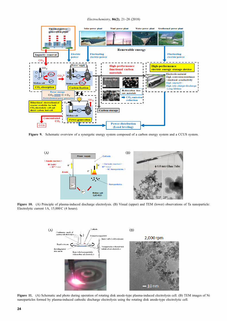
The cathodic reduction process is also interesting from theviewpoints of fixation and effective utilization of CO2. Integrationof the above two carbon plating technologies, together with othercarbon related technologies, such as using direct carbon fuel cellsand the electrochemical formation of various functional carbonmaterials, can provide a synergetic energy system composed of acarbon energy system and a CO2 capture, utilization and storage(CCUS) system (schematic overview in Fig. 9). The achievementof such a synergetic system will certainly contribute to theestablishment of the future low-carbon society.
3. Plasma-induced Discharge Electrolysis to FormNanoparticles
Even when one electrode is outside the electrolytic bath, plasma-induced stationary discharge makes electrolysis possible undercertain conditions. A principle of this process is shown inFig. 10(A).7,8 With this discharge electrolysis method, we have sofar obtained various types of metal and alloy nanoparticles: C, Al, Si,Ti, Zr, Nb, Fe, Co, Ni, Ta, Ag, Pt, NiPd, FePt, CoPt3, CoPt, Co3Pt,SmCo2, SmCo3, etc.8 As an example, visual and TEM observationsof the obtained Ta nanoparticle are shown in Fig. 10(B).
It was observed that the primary nanoparticles sized 5–20 nmare first formed just under the discharge and aggregated to formsecondary nanoparticles with diameters of around 100 nm. Thisgrowth process proceeds in the area just under the discharge duringthe initial stage of electrolysis. Based on this observation, in orderto obtain finer and more uniform nanoparticles, we constructed arotating-disk anode-type electrolytic cell and confirmed its capability,using Ni nanoparticle formation as an example.8 A schematic ofthe cell and a photo of it during operation are shown in Fig. 11(A).
Using this type of cell, we succeeded in obtaining Ninanoparticles with diameters of less than 10 nm at a rotation speedof 2,000 rpm (Fig. 11(B)).8 Encouraged by these results, weconstructed a bench-scale apparatus and are currently conductingexperiments with it (Fig. 12). Figure 13 shows the size distributionof Ni nanoparticles obtained using this apparatus.
On the other hand, pre-consumer scrap metal or used (post-consumer) metal collected from urban mines can be used as ananode in order to supply the ion to be reduced in producingnanoparticles. For this purpose, a system was configured with arotating disk (Fig. 14). Using this system, recycling and effectivereuse of various crucial metals can be achieved.
Actually, we have successfully operated apparatus equipped withthe above type of rotating disk system (Fig. 15) and confirmed thatthe recovery and effective reuse of material as a high-added-valueTa could be attained simultaneously.2,5
4. Recycling Crucial Metals Using a “Bifunctional” Electrode
Rare earth metals are indispensable in advanced and pioneeringindustries. For instance, high-performance sintered neodymium-iron-boron (Nd-Fe-B) metal magnets are widely used in hybrid-cars, air-conditioners, hard disks, etc. On the other hand, rare earthelements are scarce and unevenly distributed throughout the world.Thus, in order to secure their stable supply, it is necessary to recycle
Figure 7. Various types of carbon electrodeposited by cathodicreduction of a CO3
2¹ ion.
Figure 8. Principle of carbon film formation by cathodic reductionof a CO3
2¹ ion.
Figure 6. Photo of bench-scale barrel-type carbon plating appa-ratus.
(a) (b)
Figure 5. Carbon film on various substrates: (a) screw threads and(b) porous body.
Electrochemistry, 86(2), 21–28 (2018)
23
(B)(A)
Figure 10. (A) Principle of plasma-induced discharge electrolysis. (B) Visual (upper) and TEM (lower) observations of Ta nanoparticle:Electrolytic current 1A, 15,000C (4 hours).
(A) (B)
Figure 11. (A) Schematic and photo during operation of rotating disk anode-type plasma-induced electrolysis cell. (B) TEM images of Ninanoparticles formed by plasma-induced cathodic discharge electrolysis using the rotating disk anode-type electrolytic cell.
Figure 9. Schematic overview of a synergetic energy system composed of a carbon energy system and a CCUS system.
Electrochemistry, 86(2), 21–28 (2018)
24

rare earth metal from pre- and post-consumer scrap. However, in aconventional method, large amounts of highly concentrated acidicand alkaline solutions are used for metal and oxide dissolutionand precipitation processes, respectively. Furthermore, in order torecover each rare earth element separately, a cascade column is usedfor extraction and separation, requiring a large amount of organicsolvent. The number of cascaded steps is more than 50. The organicsolvent used here is expensive and incurs a high environmentalburden.
Taking into account the fact that the rare earth elements extractedand recovered separately through the process described above are
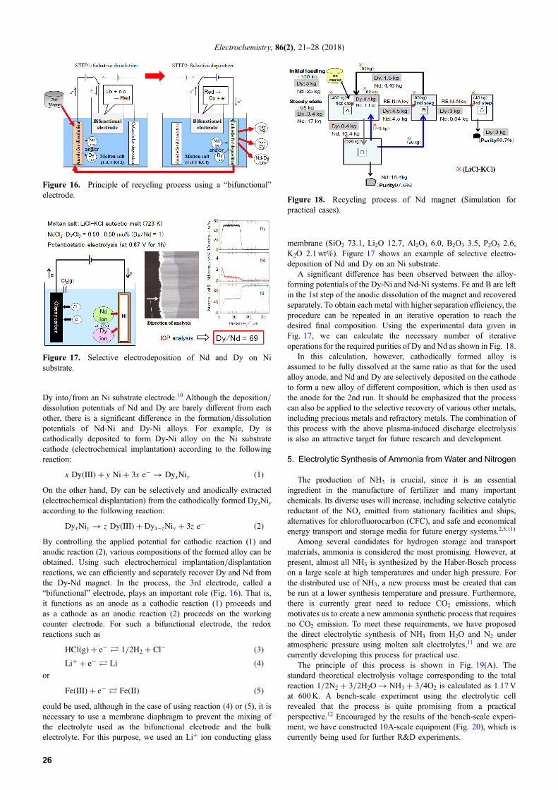
finally changed to oxide, which is converted to the correspondingmetal by the molten salt electrolysis, the most desirable approach isto skip the complicated and expensive intermediate processes andthus obtain rare earth metal directly from scrap using only moltensalt electrolysis. Against the above background, we have proposeda novel molten salt electrochemical process to recover the desiredrare earth metal from scrap.2,9 The principle of this process is shownin Fig. 16, where recycling of Dy and Nd from an Nd-magnet ischosen as an example.
The theoretical background of the process is explained as followsthrough an electrochemical implantation/displantation reaction of
Molten salt reservoir
Discharge cathodeMolten salt transport pipe
Drive motor
Rotating electrode unit
Consumable metal anode
Molten salt Solute saltex) LiCl-KCl + NiCl2
Recovering vessel
Multiple electrodes
Molten salt reservoir Electrolytic systemDischarge cathode
Heater
Figure 12. Photo and schematic of the bench scale apparatus (Production capacity: 20 g-Ni/h).
Anode Conductive vesel,Fixed
Rotating disk
Formed nano-particle
Discharge cathode
Molten saltRotating disk with slope
Recovery
Discharge cathod
Anode lead Feed stack inlet (fixed)
Insulating cover
Figure 14. Schematic of the rotating disk to provide the ion to bereduced to form nanoparticles.
0
20
40
60
80
100
0
5
10
15
20
25
10 100 1000
d10:37.9nmd90:81.8nm
d50 :51.5nm
Rotational speed 500rpmApplied current 3A x 4
Freq
uenc
y/
%
Particle size / nm
Cumulative
/ %
Figure 13. Size distribution of the Ni nanoparticles.
Figure 15. Photo and schematic of bench-scale nanoparticle production apparatus (Production capacity: 200 g/day).
Electrochemistry, 86(2), 21–28 (2018)
25
Dy into/from an Ni substrate electrode.10 Although the deposition/dissolution potentials of Nd and Dy are barely different from eachother, there is a significant difference in the formation/dissolutionpotentials of Nd-Ni and Dy-Ni alloys. For example, Dy iscathodically deposited to form Dy-Ni alloy on the Ni substratecathode (electrochemical implantation) according to the followingreaction:
x DyðIIIÞ þ y Niþ 3x e� ! DyxNiy ð1ÞOn the other hand, Dy can be selectively and anodically extracted(electrochemical displantation) from the cathodically formed DyxNiyaccording to the following reaction:
DyxNiy ! z DyðIIIÞ þ Dyx�zNiy þ 3z e� ð2ÞBy controlling the applied potential for cathodic reaction (1) andanodic reaction (2), various compositions of the formed alloy can beobtained. Using such electrochemical implantation/displantationreactions, we can efficiently and separately recover Dy and Nd fromthe Dy-Nd magnet. In the process, the 3rd electrode, called a“bifunctional” electrode, plays an important role (Fig. 16). That is,it functions as an anode as a cathodic reaction (1) proceeds andas a cathode as an anodic reaction (2) proceeds on the workingcounter electrode. For such a bifunctional electrode, the redoxreactions such as
HClðgÞ þ e� � 1=2H2 þ Cl� ð3ÞLiþ þ e� � Li ð4Þ
or
FeðIIIÞ þ e� � FeðIIÞ ð5Þcould be used, although in the case of using reaction (4) or (5), it isnecessary to use a membrane diaphragm to prevent the mixing ofthe electrolyte used as the bifunctional electrode and the bulkelectrolyte. For this purpose, we used an Li+ ion conducting glass
membrane (SiO2 73.1, Li2O 12.7, Al2O3 6.0, B2O3 3.5, P2O5 2.6,K2O 2.1wt%). Figure 17 shows an example of selective electro-deposition of Nd and Dy on an Ni substrate.
A significant difference has been observed between the alloy-forming potentials of the Dy-Ni and Nd-Ni systems. Fe and B are leftin the 1st step of the anodic dissolution of the magnet and recoveredseparately. To obtain each metal with higher separation efficiency, theprocedure can be repeated in an iterative operation to reach thedesired final composition. Using the experimental data given inFig. 17, we can calculate the necessary number of iterativeoperations for the required purities of Dy and Nd as shown in Fig. 18.
In this calculation, however, cathodically formed alloy isassumed to be fully dissolved at the same ratio as that for the usedalloy anode, and Nd and Dy are selectively deposited on the cathodeto form a new alloy of different composition, which is then used asthe anode for the 2nd run. It should be emphasized that the processcan also be applied to the selective recovery of various other metals,including precious metals and refractory metals. The combination ofthis process with the above plasma-induced discharge electrolysisis also an attractive target for future research and development.
5. Electrolytic Synthesis of Ammonia from Water and Nitrogen
The production of NH3 is crucial, since it is an essentialingredient in the manufacture of fertilizer and many importantchemicals. Its diverse uses will increase, including selective catalyticreductant of the NOx emitted from stationary facilities and ships,alternatives for chlorofluorocarbon (CFC), and safe and economicalenergy transport and storage media for future energy systems.2,5,11)
Among several candidates for hydrogen storage and transportmaterials, ammonia is considered the most promising. However, atpresent, almost all NH3 is synthesized by the Haber-Bosch processon a large scale at high temperatures and under high pressure. Forthe distributed use of NH3, a new process must be created that canbe run at a lower synthesis temperature and pressure. Furthermore,there is currently great need to reduce CO2 emissions, whichmotivates us to create a new ammonia synthetic process that requiresno CO2 emission. To meet these requirements, we have proposedthe direct electrolytic synthesis of NH3 from H2O and N2 underatmospheric pressure using molten salt electrolytes,11 and we arecurrently developing this process for practical use.
The principle of this process is shown in Fig. 19(A). Thestandard theoretical electrolysis voltage corresponding to the totalreaction 1/2N2 + 3/2H2O ¼ NH3 + 3/4O2 is calculated as 1.17Vat 600K. A bench-scale experiment using the electrolytic cellrevealed that the process is quite promising from a practicalperspective.12 Encouraged by the results of the bench-scale experi-ment, we have constructed 10A-scale equipment (Fig. 20), which iscurrently being used for further R&D experiments.
Figure 16. Principle of recycling process using a “bifunctional”electrode.
Figure 17. Selective electrodeposition of Nd and Dy on Nisubstrate.
Figure 18. Recycling process of Nd magnet (Simulation forpractical cases).
Electrochemistry, 86(2), 21–28 (2018)
26

When using the type of electrolytic cell shown in Figs. 19(A) and20, however, the minimum required electrolysis voltage (theoreticalvoltage + polarization + ohmic loss) was estimated as 2.0V, whichis mainly due to the spontaneous reaction N3¹ + 3/2H2O ¼NH3 + 3/2O2¹ inevitably involved in the process. On the otherhand, when we use an advanced-type electrolytic cell that is
composed of two cells having a hydrogen permeating metalmembrane between them (Fig. 19(B)), the required electrolysisvoltage is estimated to decrease to less than 1.5V.
Consequently, a significant decrease in the required electrolysisvoltage could be achieved by using the advanced type cell inFig. 19(B), and the reason for this has been clarified by thought
(A) (B)
Figure 19. (A) Principle of NH3 synthesis from water and nitrogen and (B) advanced-type electrolytic cell.
Figure 20. 10A-scale equipment for the electrochemical NH3
synthesis.
RenewableEnergy
WaterElectrolysis
Haber-Bosch Process
Water Electrolysis + Haber-Bosch Process (Conventional)
12MWh/ton-NH3
RenewableEnergy
ElectrolyticAmmoniaSynthesis
Direct Electrolytic Synthesis (This process)
12 8
MWh/ton-NH3
ElectrolysisVoltage
→ 2.3 V
→ 1.5 V
Figure 21. Comparison of energy required for ammonia synthesis.
Figure 22. Schematic overview of ammonia economy system.
Electrochemistry, 86(2), 21–28 (2018)
27

experiments.5 Figure 21 compares the required energy and thespecific features of two routes of synthesizing ammonia from waterand nitrogen using renewable energy: One (lower) is the proposeddirect electrolytic synthesis, and the other (upper) is conventionalwater electrolysis for obtaining hydrogen, followed by a Haber-Bosch process to synthesize ammonia from the obtained H2 and N2.The results suggest the superiority of our new process.
The energy required for the conventional Haber-Bosch processis roughly 30–35GJ/t-NH3 on average, and the top result everreported is about 28GJ/t-NH3, which is equivalent to the valueestimated for the case of using the advanced-type cell shown inFig. 19(B).2,13 However, it should be noted here that the Haber-Bosch process uses natural gas as a hydrogen source, and thus itemits a large amount of CO2.
The experimental results from the bench-scale and 10A-scale experiments, together with estimations from an economicperspective, encourage us to propose the ammonia economy systemshown in Fig. 22, where ammonia plays an important role as a keymaterial in the future environmentally friendly low-carbon society.
When we consider the role of this process from the viewpoint ofreducing CO2 emissions, we will be able to provide an effectivesolution to the serious and complicated problems of food shortagesand unsustainably high CO2 emissions.
6. Conclusions
As described above, “molten salt electrochemical processes(MSEPs)” have various attractive features from both scientific andtechnological viewpoints. They have promising and vital applica-tions in the fields of energy, the environment, resources, andmaterials. These processes can provide key technologies for thefuture low-carbon society. Detailed information on the recent R&Dactivities are provided on the web-site page of I’MSEP Co., Ltd.14
Acknowledgments
The authors deeply appreciate the great support of METI, TheSmall and Medium Enterprise Agency, NEDO, JST, Kyoto City, andKyoto Industrial Support Organization 21 to our R&D activitiesthrough their encouragement and funds. We would also like to thankTakao Kunihiro, Seiji Ohata, Yoshikazu Hyodo, Ryo Nakanishi,Takaaki Hanada, and Tatsuro Sasa for their valuable help in obtainingthe promising results of the bench-scale and 10A-scale experiments.
References
1. Applications of Molten Salts (Ed. Y. Ito), IPC Inc., (2003). [in Japanese]2. Y. Ito, T. Nishikiori, and H. Tsujimura, ECS Trans., 75(15), 115 (2016).3. Y. Ito, Tanso (Carbon), 2011, 144 (2011).4. I’MSEP Co., Ltd., “Innovative electrolytic carbon coating technology”, METI
Report, 2010. [in Japanese]5. Y. Ito, T. Nishikiori, and H. Tsujimura, Faraday Discuss., 190, 307 (2016).6. A. Yukawa, Y. Ueda, Y. Adachi, K. Tanaka, T. Katayama, S. Ohata, H. Tsujimura,
and Y. Ito, J. Surf. Fin. Soc. Jpn., 65, 41 (2014).7. H. Kawamura, K. Moritani, and Y. Ito, Plasma and Ions, 1, 29 (1998).8. Y. Ito, T. Nishikiori, and M. Tokushige, Plasma Induced Discharge Electrolysis
for Nanoparticles Production (Eds. F. Lantelme and H. Groult), Molten SaltsChemistry: From Lab to Applications, Elsevier, p. 269 (2013).
9. I’MSEP Co., Ltd., “Verification of the selective recovery of rare earth metal ina molten salt system utilizing a bifunctional electrode,” Kyoto City Report(Promotion Service Project), 2012. [in Japanese]
10. H. Konishi, T. Nohira, and Y. Ito, J. Electrochem. Soc., 148, C506 (2001).11. Y. Ito, Molten Salt and High Temperature Chemistry, Yoyuen-to-Kouon-kagaku,
46, 97 (2003). [in Japanese]12. I’MSEP Co., Ltd., “Electrolytic synthesis of ammonia under atmospheric pressure
and ammonia economy,” NEDO Report (Eco-innovation promotion project),2010. [in Japanese]
13. Y. Ito, Molten Salt Electrochemical Processes Directed Toward a Low CarbonSociety (Eds. M. Gaune-Escard and G. M. Haarberg), Molten Salt Chemistry andTechnology, John Wiley and Sons, Chap. 7.1, p. 523 (2014).
14. I’MSEP Co., Ltd., web-site page <http://imsep.co.jp>.
Electrochemistry, 86(2), 21–28 (2018)
28

![arXiv:1508.05708v3 [physics.ins-det] 28 Mar 2016 · 2016-03-29 · Thorium Molten Salt Reactor(TMSR) at the Shanghai Institute of Applied Physics (SINAP). The neutron detector signal](https://static.fdocument.pub/doc/165x107/5e9811dad7473420437a730a/arxiv150805708v3-28-mar-2016-2016-03-29-thorium-molten-salt-reactortmsr.jpg)