New generation of magnetic and luminescent nanoparticles for...
19
rsfs.royalsocietypublishing.org Review Cite this article: Lacroix L-M, Delpech F, Nayral C, Lachaize S, Chaudret B. 2013 New generation of magnetic and luminescent nanoparticles for in vivo real-time imaging. Interface Focus 3: 20120103. http://dx.doi.org/10.1098/rsfs.2012.0103 One contribution of 10 to a Theme Issue ‘Molecular-, nano- and micro-devices for real-time in vivo sensing’. Subject Areas: nanotechnology Keywords: contrast agents, magnetic resonance imaging, near-infrared, luminescent nanocrystals, quantum dots, core-shell Authors for correspondence: Lise-Marie Lacroix e-mail: [email protected] Fabien Delpech e-mail: [email protected] New generation of magnetic and luminescent nanoparticles for in vivo real-time imaging Lise-Marie Lacroix 1,2 , Fabien Delpech 1,2 , Ce ´line Nayral 1,2 , Se ´bastien Lachaize 1,2 and Bruno Chaudret 1,2 1 INSA, UPS, LPCNO (Laboratoire de Physique et Chimie des Nano-Objets), Universite ´ de Toulouse, Toulouse 31077 France 2 UMR 5215, LPCNO, CNRS, Toulouse 31077, France A new generation of optimized contrast agents is emerging, based on met- allic nanoparticles (NPs) and semiconductor nanocrystals for, respectively, magnetic resonance imaging (MRI) and near-infrared (NIR) fluorescent ima- ging techniques. Compared with established contrast agents, such as iron oxide NPs or organic dyes, these NPs benefit from several advantages: their magnetic and optical properties can be tuned through size, shape and composition engineering, their efficiency can exceed by several orders of magnitude that of contrast agents clinically used, their surface can be modified to incorporate specific targeting agents and antifolding polymers to increase blood circulation time and tumour recognition, and they can possibly be integrated in complex architecture to yield multi-modal imaging agents. In this review, we will report the materials of choice based on the understanding of the basic physics of NIR and MRI techniques and their cor- responding syntheses as NPs. Surface engineering, water transfer and specific targeting will be highlighted prior to their first use for in vivo real- time imaging. Highly efficient NPs that are safer and target specific are likely to enter clinical application in a near future. 1. Introduction Since the discovery, by chance, of X-ray potentiality by Roentgen in 1896, imaging techniques have been optimized and extended. Depending on the penetration depth, the spatial resolution and the sensitivity required, X-ray- computed tomography (CT), positron emission tomography, magnetic resonance imaging (MRI) or optical imaging, such as near-infrared (NIR) fluorescent ima- ging, may be selected as the most relevant imaging modality [1]. In all cases, enhancement of the signal-to-noise ratio, and thus of the sensitivity of these imaging techniques, requires the introduction of contrast agents, such as radioiso- topes, paramagnetic molecules or more recently inorganic nanoparticles (NPs) [2]. The latter have benefited from tremendous advances during the last two decades notably in terms of available synthetic routes. In particular, the improve- ments in solution-phase approaches now allow easy and low-cost access (compared with classical physical or vacuum methods) to well-controlled nano- probes. Prominent examples of imaging modalities which have profited from this intense research activity are MRI and NIR luminescence: a new generation of sophisticated nano-objects has reached such a stage of maturity, especially in terms of probe sensitivity, that their use has, on one hand, become standard prac- tice in in vitro biology research and, on the other hand, holds promise for in vivo real-time detection. This review intends to highlight these advances and developments that have occurred in the last few years for MRI and NIR luminescence detection. In the case of MRI, the upgrading of contrast agents based on oxide NPs to metallic NPs yields to strongly enhanced probe sensitivity. As will be detailed herein, this was achieved thanks (i) to the unprecedented magnetization related to the metallic & 2013 The Author(s) Published by the Royal Society. All rights reserved. on June 26, 2018 http://rsfs.royalsocietypublishing.org/ Downloaded from
Transcript of New generation of magnetic and luminescent nanoparticles for...

on June 26, 2018http://rsfs.royalsocietypublishing.org/Downloaded from
rsfs.royalsocietypublishing.org
ReviewCite this article: Lacroix L-M, Delpech F,
Nayral C, Lachaize S, Chaudret B. 2013 New
generation of magnetic and luminescent
nanoparticles for in vivo real-time imaging.
Interface Focus 3: 20120103.
http://dx.doi.org/10.1098/rsfs.2012.0103
One contribution of 10 to a Theme Issue
‘Molecular-, nano- and micro-devices for
real-time in vivo sensing’.
Subject Areas:nanotechnology
Keywords:contrast agents, magnetic resonance imaging,
near-infrared, luminescent nanocrystals,
quantum dots, core-shell
Authors for correspondence:Lise-Marie Lacroix
e-mail: [email protected]
Fabien Delpech
e-mail: [email protected]
& 2013 The Author(s) Published by the Royal Society. All rights reserved.
New generation of magnetic andluminescent nanoparticles for in vivoreal-time imaging
Lise-Marie Lacroix1,2, Fabien Delpech1,2, Celine Nayral1,2, Sebastien Lachaize1,2
and Bruno Chaudret1,2
1INSA, UPS, LPCNO (Laboratoire de Physique et Chimie des Nano-Objets), Universite de Toulouse,Toulouse 31077 France2UMR 5215, LPCNO, CNRS, Toulouse 31077, France
A new generation of optimized contrast agents is emerging, based on met-
allic nanoparticles (NPs) and semiconductor nanocrystals for, respectively,
magnetic resonance imaging (MRI) and near-infrared (NIR) fluorescent ima-
ging techniques. Compared with established contrast agents, such as iron
oxide NPs or organic dyes, these NPs benefit from several advantages:
their magnetic and optical properties can be tuned through size, shape
and composition engineering, their efficiency can exceed by several orders
of magnitude that of contrast agents clinically used, their surface can be
modified to incorporate specific targeting agents and antifolding polymers
to increase blood circulation time and tumour recognition, and they can
possibly be integrated in complex architecture to yield multi-modal imaging
agents. In this review, we will report the materials of choice based on the
understanding of the basic physics of NIR and MRI techniques and their cor-
responding syntheses as NPs. Surface engineering, water transfer and
specific targeting will be highlighted prior to their first use for in vivo real-
time imaging. Highly efficient NPs that are safer and target specific are
likely to enter clinical application in a near future.
1. IntroductionSince the discovery, by chance, of X-ray potentiality by Roentgen in 1896,
imaging techniques have been optimized and extended. Depending on the
penetration depth, the spatial resolution and the sensitivity required, X-ray-
computed tomography (CT), positron emission tomography, magnetic resonance
imaging (MRI) or optical imaging, such as near-infrared (NIR) fluorescent ima-
ging, may be selected as the most relevant imaging modality [1]. In all cases,
enhancement of the signal-to-noise ratio, and thus of the sensitivity of these
imaging techniques, requires the introduction of contrast agents, such as radioiso-
topes, paramagnetic molecules or more recently inorganic nanoparticles (NPs)
[2]. The latter have benefited from tremendous advances during the last two
decades notably in terms of available synthetic routes. In particular, the improve-
ments in solution-phase approaches now allow easy and low-cost access
(compared with classical physical or vacuum methods) to well-controlled nano-
probes. Prominent examples of imaging modalities which have profited from this
intense research activity are MRI and NIR luminescence: a new generation of
sophisticated nano-objects has reached such a stage of maturity, especially in
terms of probe sensitivity, that their use has, on one hand, become standard prac-
tice in in vitro biology research and, on the other hand, holds promise for in vivoreal-time detection.
This review intends to highlight these advances and developments that have
occurred in the last few years for MRI and NIR luminescence detection. In the
case of MRI, the upgrading of contrast agents based on oxide NPs to metallic
NPs yields to strongly enhanced probe sensitivity. As will be detailed herein, this
was achieved thanks (i) to the unprecedented magnetization related to the metallic
precursors+
surfactants
decomposition
nucleation
growth and/or
coalescence
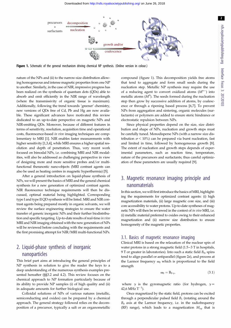
Figure 1. Schematic of the general mechanism driving chemical NP synthesis. (Online version in colour.)
rsfs.royalsocietypublishing.orgInterface
Focus3:20120103
2
on June 26, 2018http://rsfs.royalsocietypublishing.org/Downloaded from
nature of the NPs and (ii) to the narrow-size distribution allow-
ing homogeneous and intense magnetic properties from one NP
to another. Similarly, in the case of NIR, impressive progress has
been realized on the synthesis of quantum dots (QDs) able to
absorb and emit efficiently in the NIR range of wavelength
(where the transmissivity of organic tissue is maximum).
Additionally, following the trend towards ‘greener’ chemistry,
new versions of QDs free of Cd, Pb and Hg are now availa-
ble. These significant advances have motivated this review
dedicated to an up-to-date perspective on magnetic NPs and
NIR-emitting QDs. Moreover, because of different features in
terms of sensitivity, resolution, acquisition time and operational
costs, fluorescence-based in vivo imaging techniques are comp-
lementary to MRI [1]. NIR enables faster measurements with
higher sensitivity [1,3,4], while MRI ensures a higher spatial res-
olution and depth of penetration. Thus, very recent work
focused on bimodal NPs, i.e. combining MRI and NIR modal-
ities, will also be addressed as challenging perspective in view
of designing more and more sensitive probes and/or multi-
functional theranostic nano-objects (MRI contrast agents can
also be used as heating centres in magnetic hyperthermia) [5].
After a general introduction on liquid-phase synthesis of
NPs, we will present the basics of MRI and the general chemical
synthesis for a new generation of optimized contrast agents.
NIR fluorescence technique requirements will then be dis-
cussed, optimal material being highlighted. Corresponding
type I and type II QD synthesis will be listed. MRI and NIR con-
trast agents being prepared mostly in organic solvants, we will
review the surface engineering strategies to ensure the water
transfer of generic inorganic NPs and their further biodistribu-
tion and specific targeting. Up-to-date results of real-time in vivoMRI and NIR imaging obtained with the new generation of NPs
will be reviewed before concluding with the requirements and
the first promising attempt for NIR/MRI multi-functional NPs.
2. Liquid-phase synthesis of inorganicnanoparticles
This brief part aims at introducing the general principles of
NP synthesis in solution to give the reader the keys to a
deep understanding of the numerous synthesis examples pre-
sented hereafter (§§3.2 and 4.2). This review focuses on the
chemical approach to NP formation particularly because of
its ability to provide NP samples (i) of high quality and (ii)
in adequate amounts for further biological use.
Colloidal solutions of NPs of various natures (metallic,
semiconducting and oxides) can be prepared by a chemical
approach. The general strategy followed relies on the decom-
position of a precursor, typically a salt or an organometallic
compound (figure 1). This decomposition yields free atoms
that tend to aggregate and form small seeds during the
nucleation step. Metallic NP synthesis may require the use
of a reducing agent to convert oxidized atoms (Mnþ) into
metallic atoms (M0). The seeds formed during the nucleation
step then grow by successive addition of atoms, by coalesc-
ence or through a ripening based process [6,7]. To prevent
NPs from aggregation and sintering, organic molecules (sur-
factants) or polymers are added to ensure steric hindrance or
electrostatic repulsion between NPs.
Since physical properties depend on the size, size distri-
bution and shape of NPs, nucleation and growth steps must
be carefully tuned. Monodisperse NPs (with a narrow size dis-
tribution s , 10%) can be prepared via burst nucleation, fast
and limited in time, followed by homogeneous growth [8].
The extent of nucleation and growth steps depends of exper-
imental parameters, such as reaction time, temperature,
nature of the precursors and surfactants; thus careful optimiz-
ation of these parameters are usually required [9].
3. Magnetic resonance imaging principle andnanomaterials
In this section, we will first introduce the basics of MRI, highlight-
ing the requirements for optimized contrast agents: (i) high
magnetization materials, (ii) large magnetic core size, and (iii)
core accessibility to water protons. Up-to-date syntheses of mag-
netic NPs will then be reviewed in the context of in vivo MRI, i.e.
(i) metallic material preferred to oxides owing to their enhanced
magnetization and (ii) narrow size distribution to ensure
homogeneity of the magnetic properties.
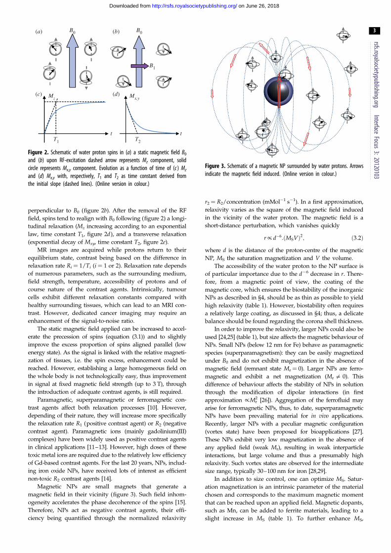
3.1. Basics of magnetic resonance imagingClinical MRI is based on the relaxation of the nuclear spin of
water protons in a strong magnetic field (1.5–3 T in hospitals,
9 T or greater in laboratories). Into such a static field B0, spins
tend to align parallel or antiparallel (figure 2a), and process at
the Larmor frequency v0 which is proportional to the field
strength
v0 ¼ B0�g; ð3:1Þ
where g is the gyromagnetic ratio (for hydrogen, g ¼
42,6 MHz T– 1).
Once magnetized by the static field, protons can be excited
through a perpendicular pulsed field B1 (rotating around the
B0 axis at the Larmor frequency, i.e. in the radiofrequency
(RF) range), which leads to a magnetization Mxy that is
B0(a) (b)
(c) (d)
B0
B1
Mz Mx,y
T2
t tT1
Figure 2. Schematic of water proton spins in (a) a static magnetic field B0
and (b) upon RF-excitation dashed arrow represents Mz component, solidcircle represents Mx,y component. Evolution as a function of time of (c ) Mz
and (d) Mx,y with, respectively, T1 and T2 as time constant derived fromthe initial slope (dashed lines). (Online version in colour.)
Figure 3. Schematic of a magnetic NP surrounded by water protons. Arrowsindicate the magnetic field induced. (Online version in colour.)
rsfs.royalsocietypublishing.orgInterface
Focus3:20120103
3
on June 26, 2018http://rsfs.royalsocietypublishing.org/Downloaded from
perpendicular to B0 (figure 2b). After the removal of the RF
field, spins tend to realign with B0 following (figure 2) a longi-
tudinal relaxation (Mz increasing according to an exponential
law, time constant T1, figure 2d), and a transverse relaxation
(exponential decay of Mxy, time constant T2, figure 2e).
MR images are acquired while protons return to their
equilibrium state, contrast being based on the difference in
relaxation rate Ri ¼ 1/Ti (i ¼ 1 or 2). Relaxation rate depends
of numerous parameters, such as the surrounding medium,
field strength, temperature, accessibility of protons and of
course nature of the contrast agents. Intrinsically, tumour
cells exhibit different relaxation constants compared with
healthy surrounding tissues, which can lead to an MRI con-
trast. However, dedicated cancer imaging may require an
enhancement of the signal-to-noise ratio.
The static magnetic field applied can be increased to accel-
erate the precession of spins (equation (3.1)) and to slightly
improve the excess proportion of spins aligned parallel (low
energy state). As the signal is linked with the relative magneti-
zation of tissues, i.e. the spin excess, enhancement could be
reached. However, establishing a large homogeneous field on
the whole body is not technologically easy, thus improvement
in signal at fixed magnetic field strength (up to 3 T), through
the introduction of adequate contrast agents, is still required.
Paramagnetic, superparamagnetic or ferromagnetic con-
trast agents affect both relaxation processes [10]. However,
depending of their nature, they will increase more specifically
the relaxation rate R1 (positive contrast agent) or R2 (negative
contrast agent). Paramagnetic ions (mainly gadolinium(III)
complexes) have been widely used as positive contrast agents
in clinical applications [11–13]. However, high doses of these
toxic metal ions are required due to the relatively low efficiency
of Gd-based contrast agents. For the last 20 years, NPs, includ-
ing iron oxide NPs, have received lots of interest as efficient
non-toxic R2 contrast agents [14].
Magnetic NPs are small magnets that generate a
magnetic field in their vicinity (figure 3). Such field inhom-
ogeneity accelerates the phase decoherence of the spins [15].
Therefore, NPs act as negative contrast agents, their effi-
ciency being quantified through the normalized relaxivity
r2 ¼ R2/concentration (mMol21 s21). In a first approximation,
relaxivity varies as the square of the magnetic field induced
in the vicinity of the water proton. The magnetic field is a
short-distance perturbation, which vanishes quickly
r/ d�6:ðMSVÞ2; ð3:2Þ
where d is the distance of the proton-centre of the magnetic
NP, MS the saturation magnetization and V the volume.
The accessibility of the water proton to the NP surface is
of particular importance due to the d26 decrease in r. There-
fore, from a magnetic point of view, the coating of the
magnetic core, which ensures the biostability of the inorganic
NPs as described in §4, should be as thin as possible to yield
high relaxivity (table 1). However, biostability often requires
a relatively large coating, as discussed in §4; thus, a delicate
balance should be found regarding the corona shell thickness.
In order to improve the relaxivity, larger NPs could also be
used [24,25] (table 1), but size affects the magnetic behaviour of
NPs. Small NPs (below 12 nm for Fe) behave as paramagnetic
species (superparamagnetism): they can be easily magnetized
under B0 and do not exhibit magnetization in the absence of
magnetic field (remnant state Mr¼ 0). Larger NPs are ferro-
magnetic and exhibit a net magnetization (Mr = 0). This
difference of behaviour affects the stability of NPs in solution
through the modification of dipolar interactions (in first
approximation /Mr2 [26]). Aggregation of the ferrofluid may
arise for ferromagnetic NPs, thus, to date, superparamagnetic
NPs have been prevailing material for in vivo applications.
Recently, larger NPs with a peculiar magnetic configuration
(vortex state) have been proposed for bioapplications [27].
These NPs exhibit very low magnetization in the absence of
any applied field (weak Mr), resulting in weak interparticle
interactions, but large volume and thus a presumably high
relaxivity. Such vortex states are observed for the intermediate
size range, typically 30–100 nm for iron [28,29].
In addition to size control, one can optimize MS. Satur-
ation magnetization is an intrinsic parameter of the material
chosen and corresponds to the maximum magnetic moment
that can be reached upon an applied field. Magnetic dopants,
such as Mn, can be added to ferrite materials, leading to a
slight increase in MS (table 1). To further enhance MS,

Table 1. r2 relaxivities of magnetic NPs. CLIO: cross-linked iron oxide NPs, used in clinical applications. SPM, superparamagnetic; FM, ferromagnetic; DMSA, 2,3-dimercaptosuccinic acid; PEG, polyethylenglycol; TMAOH, tetramethylammonium hydroxide.
material MS (emu/gmetal)core size(nm)
magneticstate
organic corona
r2 (s21 mM21) B0 (T) refsligand size (nm)
CLIO-FexOy — — — 62 [16]
Fe3O4 101 12 — DMSA 2 218 1.5 [16]
— 10 — PEG PEI 7 40 1.5 [17]
— 10 — PEI 2 75 1.5 [17]
MnFe2O4 �60 6 — DMSA 2 208 1.5 [16]
�90 9 — DMSA 2 265 1.5 [16]
110 12 — DMSA 2 358 1.5 [16]
Fe@Fe3O4 70 10 FM PEG 2 129 1.5 [18]
140 16 FM DMSA 2 324 9.4 [19]
112 15 FM PEG 15 67 3 [20]
164 15 FM PEG 15 220 3 [20]
Co@Au — 30 – 90 — — 107 7 [21]
FeCo@C 162 4 SPM PEG 17 185 1.5 [22]
215 7 SPM PEG 17 644 1.5 [22]
FePt 125 9 SPM TMAOH 2 239 4.7 [23]
rsfs.royalsocietypublishing.orgInterface
Focus3:20120103
4
on June 26, 2018http://rsfs.royalsocietypublishing.org/Downloaded from
metals, such as Fe or Co, should be preferred to their oxide
counterparts (table 1). Though contrast agents used clinically
are nowadays only based on superparamagnetic iron oxide
NPs [30], the design of optimized contrast agents would
benefit from metallic NPs, providing that these NPs do not
exhibit toxicity [31]. Thus, we will focus our discussion on
the recent strategies developed to synthesize and protect
metallic NPs with optimized properties.
3.2. Synthesis of magnetic nanoparticlesMultiple strategies have been developed to synthesize mono-
dispersed iron oxide NPs (maghemite g-Fe2O3 or magnetite
Fe3O4), either in aqueous [32] or in organic solvents [33]. Size
control could be reached by the decomposition of organometal-
lic precursors at high temperature in the presence of long alkyl
chain surfactants [34,35], further synthesis information being
found in recent review articles [36,37]. Concerning magnetic
dopants, they can be added in the spinel structure by
co-reduction at high temperature of organometallic precursors,
such as Mn(acac)2 and Fe(acac)3 [38].
Here, we will focus our attention on synthesis of metallic
NPs, promising higher magnetization, as explained pre-
viously. Iron being highly reactive towards oxidation,
metallic Fe NPs were mainly prepared in organic solvents
(table 2) [56]. Classically, Fe(CO)5 was decomposed at high
temperature in the presence of long-chain amines [39,57].
Though highly toxic, this precursor benefited from Fe atoms
already reduced (oxidation degree 0); therefore no reducing
agents were required. However, the magnetic properties of
the NPs obtained were generally lower than the bulk value,
owing to their intrinsic carburation from CO byproduct [58].
To prevent such carburation, Fe(CO)5 can be replaced by
iron salts or organometallic compounds, whose decomposition
did not yield any carbon source. Owing to their high stability,
the decomposition and reduction of iron salts required harsh
conditions. For instance, FeCl2 could be reduced in water by
sodium borohydride, but boron contamination has been
found to decrease the NP moment [18]. Therefore, decompo-
sition of organometallic compounds such as Fe(C5H5)(C6H7)
[19] or fFe[N(SiMe3)2]2g2 [42,59] under dihydrogen atmos-
phere could be preferred to yield unoxidized iron NPs in
mild conditions (bulk magnetization). Owing to its high reac-
tivity, the latter amido precursor could also be reduced solely
by a long-chain amine in the absence of H2 [60]. The optimiz-
ation of the nucleation and growth steps, through the tuning
of experimental parameters (temperature and surfactants),
yielded Fe NPs with unprecedented size and shape control
in the range 1–100 nm (figure 4a,b).
Cobalt NPs can be prepared following similar procedures.
Co2(CO)8 could be decomposed at high temperature to yield
monodisperse NPs [44,62]. As observed for Fe, the binding
of –CO species at the NPs’ surface decreased their magnetic
properties [63]. Cobalt salt (CoCl2) can be reduced with a
strong reducing agent (superhydride LiEt3BH) and yield
NPs of the 1-Co crystalline phase with degraded magnetic
properties prior to annealing treatment [45]. Co can crystallize
in a hexagonal close packed structure which exhibits
optimized magnetic properties. Benefiting from the crystallo-
graphic unicity of the c-axis, intensive research has been
devoted to the synthesis of anisotropic Co NPs. Polyol syn-
thesis [46] along organometallic approaches [47,48] yielded
single crystalline Co nanorods with a relatively narrow size
distribution (figure 4c). Though nanorods have never been
tested for MRI purposes, they could potentially present high
relaxivity, analogous to elongated Co@Au nanowontons,
prepared through physical process [21] (table 1).
To further enhance the magnetic moment, Fe or Co could
be replaced by FeCo NPs, providing that highly crystalline
NPs with optimized composition (60% Fe and 40% Co)
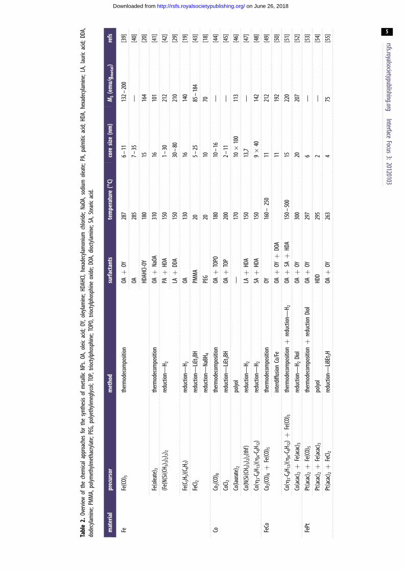
Tabl
e2.
Over
view
ofth
ech
emica
lapp
roac
hes
for
the
synt
hesis
ofm
etall
icNP
s.OA
,olei
cac
id;O
Y,ol
eylam
ine;
HDAH
Cl,he
xade
cylam
oniu
mch
lorid
e;Na
OA,s
odiu
mol
eate
;PA,
palm
itic
acid
;HDA
,hex
adec
ylam
ine;
LA,l
auric
acid
;DDA
,do
decy
lamin
e;PM
MA,
polym
ethy
lmet
hacry
late;
PEG,
polye
thyle
negl
ycol
;TOP
,trio
ctylp
hosp
hine
;TOP
O,tri
octy
lpho
sphi
neox
ide;
DOA,
dioc
tylam
ine;
SA,S
tear
icac
id.
mat
eria
lpr
ecur
sor
met
hod
surf
acta
nts
tem
pera
ture
(88888C)
core
size
(nm
)M
S(e
mu/
g met
al)
refs
FeFe
(CO)
5th
erm
odec
ompo
sition
OAþ
OY28
76–
1113
2–20
0[3
9]
OA28
57–
35—
[40]
HDAH
Cl-OY
180
1516
4[2
0]
Fe(o
leate
) 3th
erm
odec
ompo
sition
OAþ
NaOA
310
1610
1[4
1]
(Fe(
N(Si
(CH 3
) 3)2) 2
) 2re
ducti
on—
H 2PAþ
HDA
150
1–30
212
[42]
LAþ
DDA
150
30–
8021
0[2
9]
Fe(C
5H5)(
C 6H 7
)re
ducti
on—
H 2OA
130
1614
0[1
9]
FeCl 2
redu
ction
—LiE
t 3BH
PMM
A20
5–25
85–
184
[43]
redu
ction
—Na
BH4
PEG
2010
70[1
8]
CoCo
2(CO)
8th
erm
odec
ompo
sition
OAþ
TOPO
180
10–
16—
[44]
CoCl 2
redu
ction
—LiE
t 3BH
OAþ
TOP
200
2–11
—[4
5]
Co(la
urat
e)2
polyo
l—
170
10�
100
113
[46]
Co(N
(Si(C
H 3) 3)
2) 2(th
f)re
ducti
on—
H 2LAþ
HDA
150
13,7
—[4
7]
Co(h
3-C8H
13)(h
4-C8H
12)
redu
ction
—H 2
SAþ
HDA
150
9�
4014
2[4
8]
FeCo
Co2(C
O)8þ
Fe(C
O)5
ther
mod
ecom
posit
ionOY
160–
250
1121
2[4
9]
inte
rdiff
usion
Co/F
eOAþ
OYþ
DOA
1119
2[5
0]
Co(h
3-C8H
13)(h
4-C8H
12)þ
Fe(C
O)5
ther
mod
ecom
posit
ionþ
redu
ction
—H 2
OAþ
SAþ
HDA
150–
500
1522
0[5
1]
Co(a
cac) 2þ
Fe(a
cac) 3
redu
ction
—H 2
Diol
OAþ
OY30
020
207
[52]
FePt
Pt(a
cac) 2þ
Fe(C
O)5
ther
mod
ecom
posit
ionþ
redu
ction
Diol
OAþ
OY29
76
—[5
3]
Pt(a
cac) 2þ
Fe(a
cac) 3
polyo
lHD
D29
52
—[5
4]
Pt(a
cac) 2þ
FeCl 2
redu
ction
—LiB
Et3H
OAþ
OY26
34
75[5
5]
rsfs.royalsocietypublishing.orgInterface
Focus3:20120103
5
on June 26, 2018http://rsfs.royalsocietypublishing.org/Downloaded from
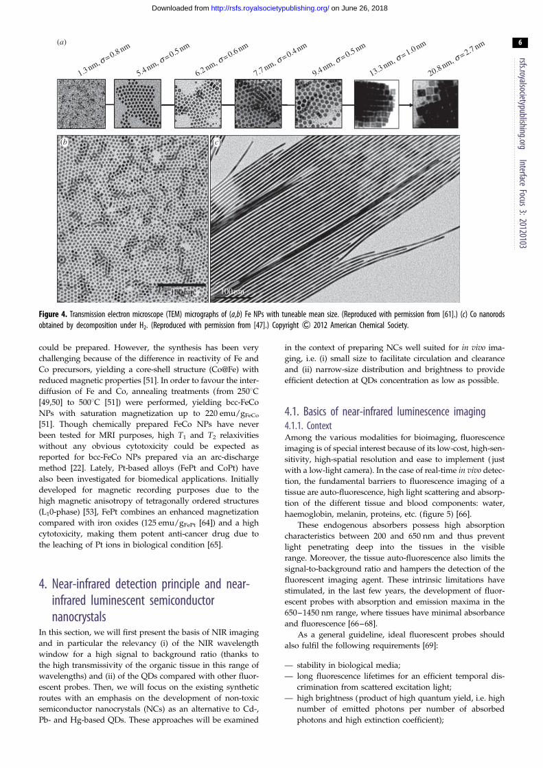
1.3 nm, s = 0.8 nm
5.4 nm, s = 0.5 nm
6.2 nm, s = 0.6 nm
7.7 nm, s = 0.4 nm
9.4 nm, s = 0.5 nm
13.3 nm, s = 1.0 nm
20.8 nm, s = 2.7 nm(a)
100 nm 100 nm
(b) (c)
Figure 4. Transmission electron microscope (TEM) micrographs of (a,b) Fe NPs with tuneable mean size. (Reproduced with permission from [61].) (c) Co nanorodsobtained by decomposition under H2. (Reproduced with permission from [47].) Copyright & 2012 American Chemical Society.
rsfs.royalsocietypublishing.orgInterface
Focus3:20120103
6
on June 26, 2018http://rsfs.royalsocietypublishing.org/Downloaded from
could be prepared. However, the synthesis has been very
challenging because of the difference in reactivity of Fe and
Co precursors, yielding a core-shell structure (Co@Fe) with
reduced magnetic properties [51]. In order to favour the inter-
diffusion of Fe and Co, annealing treatments (from 2508C[49,50] to 5008C [51]) were performed, yielding bcc-FeCo
NPs with saturation magnetization up to 220 emu/gFeCo
[51]. Though chemically prepared FeCo NPs have never
been tested for MRI purposes, high T1 and T2 relaxivities
without any obvious cytotoxicity could be expected as
reported for bcc-FeCo NPs prepared via an arc-discharge
method [22]. Lately, Pt-based alloys (FePt and CoPt) have
also been investigated for biomedical applications. Initially
developed for magnetic recording purposes due to the
high magnetic anisotropy of tetragonally ordered structures
(L10-phase) [53], FePt combines an enhanced magnetization
compared with iron oxides (125 emu/gFePt [64]) and a high
cytotoxicity, making them potent anti-cancer drug due to
the leaching of Pt ions in biological condition [65].
4. Near-infrared detection principle and near-infrared luminescent semiconductornanocrystals
In this section, we will first present the basis of NIR imaging
and in particular the relevancy (i) of the NIR wavelength
window for a high signal to background ratio (thanks to
the high transmissivity of the organic tissue in this range of
wavelengths) and (ii) of the QDs compared with other fluor-
escent probes. Then, we will focus on the existing synthetic
routes with an emphasis on the development of non-toxic
semiconductor nanocrystals (NCs) as an alternative to Cd-,
Pb- and Hg-based QDs. These approaches will be examined
in the context of preparing NCs well suited for in vivo ima-
ging, i.e. (i) small size to facilitate circulation and clearance
and (ii) narrow-size distribution and brightness to provide
efficient detection at QDs concentration as low as possible.
4.1. Basics of near-infrared luminescence imaging4.1.1. ContextAmong the various modalities for bioimaging, fluorescence
imaging is of special interest because of its low-cost, high-sen-
sitivity, high-spatial resolution and ease to implement ( just
with a low-light camera). In the case of real-time in vivo detec-
tion, the fundamental barriers to fluorescence imaging of a
tissue are auto-fluorescence, high light scattering and absorp-
tion of the different tissue and blood components: water,
haemoglobin, melanin, proteins, etc. (figure 5) [66].
These endogenous absorbers possess high absorption
characteristics between 200 and 650 nm and thus prevent
light penetrating deep into the tissues in the visible
range. Moreover, the tissue auto-fluorescence also limits the
signal-to-background ratio and hampers the detection of the
fluorescent imaging agent. These intrinsic limitations have
stimulated, in the last few years, the development of fluor-
escent probes with absorption and emission maxima in the
650–1450 nm range, where tissues have minimal absorbance
and fluorescence [66–68].
As a general guideline, ideal fluorescent probes should
also fulfil the following requirements [69]:
— stability in biological media;
— long fluorescence lifetimes for an efficient temporal dis-
crimination from scattered excitation light;
— high brightness (product of high quantum yield, i.e. high
number of emitted photons per number of absorbed
photons and high extinction coefficient);

106
105
104
103
102
10
1
0.1 1
proteinscollagen
melanin
HbO2Hb
water
wavelength (mm)
abso
rptio
n co
effi
cien
t (cm
–1)
10
Figure 5. Absorbance of various tissue and blood components from 200 nmto 10 mm. (Reproduced with permission from [66]. Copyright & 2012American Chemical Society.)
rsfs.royalsocietypublishing.orgInterface
Focus3:20120103
7
on June 26, 2018http://rsfs.royalsocietypublishing.org/Downloaded from
— narrow, symmetric emission bands and large Stokes shifts
to easily separate the excitation and emission; and
— no toxicity or interference with cell physiology.
The organic fluorescent dyes (cyanines, pyrroles- or por-
phyrins-based cycles, squaraines and borondipyrromethene
classes) [66], which were historically first used in NIR biodetec-
tion [70], are far from ideal probes. In the far-red/NIR
wavelength range, they suffer from rather low quantum
yield, photobleaching (making them unsuitable for extended
periods of observation) and broad emission spectra, which
create overlapping detection ranges (inadequate for simul-
taneous multi-colour applications) [66,71]. Even if remarkable
progress has been made to improve the performance of dye-
doped silica NPs and to develop new probes such as up-con-
verting NPs [72,73] or noble metal (gold and silver)
nanoclusters [5,74], the optical performances (especially QYs)
are not yet competitive enough.
Among the NIR fluorescent probes [5], QDs offer currently
the best optical properties and appear as a very powerful and
essential tool in biodetection. Indeed, they exhibit large molar
extinction coefficients, high QY (greater than 50%), narrow
and symmetric photoluminescence (PL) emission bands,
size-tunable emission and absorption spectra, large two-
photon action cross section and high photostability [69].
However, QDs suffer from the drawback of blinking (intermit-
tence in light emission), which is problematic in the case of
single molecule tracking [75], instability of QY in different
media and possible emission variability due to slight size
modification between chemical batches.
4.1.2. Quantum dots specificitiesOwing to their nanoscale dimension, the intrinsic physical
characteristics of the material are transformed by quantum
effects below a certain size limit (Bohr radius), which
ranges approximately from 2 to 50 nm according to the
material [76]. At these sizes, NCs lie in between the atomic
and molecular limit (discrete density of electronic levels)
and the extended crystalline limit (continuous bands, i.e.
the valence band and the conduction band) of bulk
semiconductors. This leads to size-dependent optical proper-
ties (figure 6) [78], the maximum emission wavelength
attainable being that of the bulk material.
When NCs are excited by quanta of energy, an electron is
promoted from the valence band into the conduction band,
leaving a hole in the valence band (electron-hole pair, i.e.
exciton generation). The exciton recombination results in
light emission at a wavelength longer than the absorbed
light (Stokes shift). Several factors can be used to vary
band gap and, thus, to control absorption and luminescence
wavelengths of the NCs. Classically, band gap engineering
can be achieved through the variation of (i) the particle
size, or (ii) of the composition. Several alternatives exist for
modifying the band gap: (iii) doping the semiconductor
host NCs with the incorporation of small amount of impuri-
ties, and (iv) modifying the internal structure (homogeneous
versus graded), for example, in ternary system QDs like
CdSe12xTex [79]. Thanks to these strategies, there are now a
large variety of QDs that luminesce in the NIR region as
illustrated in figure 7.
Finally, one can find a last strategy for designing
NIR-emitting QDs that is based on core/shell (C/S) architec-
ture: the core and shell are rationally chosen in order to
favour the relaxation of a conduction band electron of the
core into the valence band of the shell (type II QDs; figure
9c) [102]. The staggered band alignment leads to a smaller
effective band gap than each one of the constituting core and
shell materials. This aspect will be described in more
detail in §5.1 devoted to heteronanocrystal, i.e. NCs incorpor-
ating two or more materials organized in C/S or core/
multi-shell architecture.
4.2. Luminescent semiconductor nanocrystals: chemicalsynthesis of NIR-emitting core nanocrystals
The literature reports a large variety of Cd-, Pb- or Hg-based
QDs for which the synthetic routes can be generally classified
in two families, according the synthetic medium (aqueous or
not). Different protocols have been described in water to
produce II–VI semiconductors, such as CdTe, CdSexTe12x,
HgTe, CdxHg12xTe or CdxHg12xSe QDs [103]. The major
advantages of this aqueous medium approach are (i) the
environmentally friendly medium, (ii) the ease to scale up
to gram scale amounts for commercial purpose and (iii) the
aqueous compatibility for applications, in particular bio-
medical imaging [104]. However, the size distribution is
often broad and post-preparative procedures (size-selective
precipitation) are required [80].
In this context, the development of the alternative
hot-injection method, i.e. the synthesis of NCs in high-
temperature boiling organic solvents is considered as one of
the main milestones in the chemistry of QDs. The temporal
separation of the nucleation and the growth of the seeds
gave access to high-quality NCs with narrow-size distribution
(5–10% s.d.) without laborious size-selective precipitation pro-
cedure. Since the first published articles (Murray et al. [105] for
CdE (E ¼ S, Se, Te)), synthetic improvements have allowed an
ongoing trend towards simpler and safer procedures (replace-
ment of the hazardous [106] or expensive chemicals [107],
decrease in reaction temperature to approx. 1008C [108]).
Moreover, the widespread success of the hot-injection strategy
is also largely because of its versatility, in particular in terms of
chemical variety. The extension of the list of semiconductor

molecule semiconductornanocrystal
bulksemiconductor
conductionband
valenceband
Eg
E
LUMO
HOMO
Figure 6. Electronic energy states of a semiconductor in the transition from discrete molecules to nanosized crystals and bulk crystals. Shading denotes ground-stateelectron occupation. (Adapted from [77]. Copyright & 2012 American Chemical Society.) (Online version in colour.)
600 700 800 900 1000
emission wavelength (nm)
1100 1200 1300 1400 1500
1.3 nm
1.3 nm
II–VI
IV–VI
III–V
II3–V2
I–III–VI2
IV
I2–VI
CdTeCdSTe
CdSeTeCdHgTe ~6 nm
PbSSe ~5 nm
InPAs ~2.5 nm
InP
InAs
Cd3As2
Cd3P2
3 nm 10 nm
6.5 nm
17 nm8.3 nm
6 nm
7.6 nm
5 nm
HgTe
Pbs
PbSePbTe
5.5 nm
5.5 nm
3 nm
2.6 nm
Cu-InP5 nm
5.8 nm
6.5 nm
3 nm
2 nm
2 nm
CuInS2CuInSe2
AgInS2
Ag2Se
Ag2Te
Ag2S
2 nm
2 nm
3.3 nm 4.7 nm
6.3 nm3.4 nm
3.2 nm
2 nm
1.5 nm
1.5 nm
2 nm 16 nm
2 nm
1.5 nm
5 nm
10 nm
Ge
Figure 7. Composition, size and wavelength ranges of reported NIR-emitting QDs prepared via solution-based methodologies. Emission wavelengths reportedfor constant size NCs containing different proportions of elements are represented with broken lines rectangle. The references used for the figure are the following:II – VI [79 – 84], IV – VI [85 – 89], III – V [90 – 93], II3 – V2 [94,95], I – III – VI2 [96,97], IV [98,99] and I2 – VI [100,101]. (Online version in colour.)
rsfs.royalsocietypublishing.orgInterface
Focus3:20120103
8
on June 26, 2018http://rsfs.royalsocietypublishing.org/Downloaded from
materials to high quality (in terms of monodispersity and opti-
cal emission) IV–VI QDs such as PbE (E¼ S [86], Se [109], Te
[110]) is one of the valuable consequences [111]. Finally, emer-
ging materials such as II3–V2 are also worth citing: for
instance, a room temperature procedure has recently been
developed to yield Cd3P2 QDs that emit in the NIR region
[112] and can be envisioned for biodetection. It should also
be noted that in case of mercury-based NCs, the aqueous strat-
egy remains the best-suited and almost exclusive approach
[103,111].
In the context of in vivo applications, the issue of meta-
bolic clearance is still an open and unresolved question. To
avoid any dilemma, one strategy is to extend the NC family
towards more environmentally friendly elements than Cd,
Pb or Hg [113]. We have chosen to detail this attractive per-
spective in §4.2.1, 4.2.2 and 4.2.3.
4.2.1. Synthesis of Pb-free IV – VI semiconductors nanocrystals(GeE, SnE, E ¼ S, Se, Te)
While the use of precisely controlled reaction conditions (air-
and water-free atmosphere) can be seen as a major drawback
when aiming at simple and straightforward procedures, these
requirements offer, on the other hand, the opportunity to

rsfs.royalsocietypublishing.orgInterface
Focus3:20120103
9
on June 26, 2018http://rsfs.royalsocietypublishing.org/Downloaded from
introduce novel precursors yielding unexplored materials for
NCs, such as the tin and germanium chalcogenides [114].
The preparation of SnTe NCs [115] using the sophisticated tin
complex bis[bis(trimethylsilyl)amino]tin(II) (Sn[N(SiMe3)2]2)
and trioctylphosphine telluride was the starting shot towards
materials involving these lighter elements of the Pb group.
Today, a large variety of compositions (GeS, GeSe, GeTe,
GexSn12xSe, SnSxSe12x, etc.) and morphology (sphere, sheet
and needle) with tunable band gap in the NIR region is acces-
sible [114]. Although the emission properties have not yet been
explored, tin and germanium monochalcogenide represent
very promising materials which deserve to be tested in the
context of biodetection.
4.2.2. Synthesis of III – V semiconductors nanocrystals(InP and InAs)
Following the same tendency towards ‘greener’ material, III–V
semiconductors are generally viewed as a highly relevant
alternative. This is in particular the case for InP NCs which
have been rapidly identified as one of the most promising
alternatives to Cd- and Pb-based QDs and have been the focus
of the majority of the research efforts devoted to III–V QDs.
InP NCs were first prepared in 1994 [116] following, at the
time recently published, the hot-injection procedure developed
for CdE (E¼ S, Se, Te) QDs with indium oxalate and
tris(trimethylsilyl)phosphine (P(SiMe3)3). Longer reaction times
(3–7 days) were required to yield good cristallinity. The progress
towards easy, reliable and controlled synthesis (i.e. in non-
coordinating solvent) followed that of their II–VI analogues
[117], but remains one step behind, particularly for the size
control. The preparation of QDs larger than 5 nm is still a challen-
ging question. This issue is of central importance because
absorption wavelengths higher to 650 nm are at the upper limit
of the current attainable range with InP [90]. It has recently
been shown that the formation of a mixed oxide shell InPOx at
the surface of the NCs is probably the reason of this growth inhi-
bition. This is a consequence of the oxophilic character of
phosphorus and of a side reaction of the carboxylate ligand
occurring at the temperature (2308C–3008C) required for the for-
mation of NCs, which generates oxidative conditions in the
reaction medium [118]. However, the doping strategy proved
to be successful and allow emission wavelengths up to
1100 nm to be reached [91]. InAs NCs were also prepared
following the hot-injection method, usually by the reaction of
As(SiMe3)3 and indium chloride [119] or acetate [117]. In the
latter case, the QD size can be controlled to access a range of
emission wavelengths well suited for biodetection purposes,
i.e. between 700 and 1400 nm, with diameters approximately
less than 6 nm [93]. As an example, InAs NPs of 3.2 nm diameter
emitting at 750 nm can be easily cleared from the body [120].
4.2.3. Other semiconductors (IV, I2 – VI and I – III – VI2 types) forNIR-emitting nanocrystals
Over the last decade, significant progress has been made con-
cerning the chemistry of NCs of materials as alternatives to
II–VI, IV–VI and III–V. So far, two main families have been
the focus of the majority of research efforts: elemental group
IV (Si, Ge) semiconductors and I–III–VI2 chalcopyrite types
such as CuInE2 (E ¼ S, Se) or AgInS2 [96]. In the latter case,
the synthetic strategy is essentially the same as the one devel-
oped for the hot-injection method for II–VI, IV–VI and III–V
materials, i.e. in coordinating (TOPO) [121] or non-
coordinating (dioctylphtalate [122], ODE [123]) solvents. Con-
cerning group IV element NCs, the synthesis is far less
developed. Two main solution strategies exist and involve
either strong reducing agents (zintl salts, LiAlH4, K/Na
alloy) and/or high-temperature procedures (usually supercriti-
cal thermolysis condition) [98]. An exception to this rule are
the approaches developed by the Boyle [124] and Klimov
[99] groups, who took advantage of the reactivity of Ge(II) pre-
cursors using hot-injection approach. Very recently, silver
chalcogenide Ag2E [101] and in particular silver sulfide
Ag2S [125] were identified as promising materials for NIR-
emitting QDs. For these NCs, both aqueous [100,126,127]
and organic [101,125,128] solvent approaches were developed
with similar results in terms of size distribution and optical
quality, which opens the way for in vivo studies [100,126].
5. Surface modification and probe developmentIn view of their applications for biological imaging, NPs
cannot be use directly after their synthesis for two major
reasons. First, because nano-objects have high surface to
volume ratios, a large fraction of the constituent atoms are
located on the surface. These atoms are incompletely
bonded within the crystal lattice, thus disrupting the crystal-
line periodicity and leaving one or more ‘dangling orbital’ on
each atom pointed outward from the crystal. While partially
stabilized through dative ligand–metal bonds, the organic
passivation is generally insufficient to provide inertness to
the biological medium and/or to air. These surface atoms,
indeed, remain highly reactive and are usually prone to
oxidation. A general strategy to improve NPs’ surface passi-
vation is the overgrowth of a protecting shell around the
core, affording chemical stability and preservation of the
physical properties. A second requirement aiming at exploit-
ing the magnetic or luminescent properties for biodetection is
the solubility of the NPs in physiological media. As discussed
in the previous sections, the NPs of best quality are generally
produced in non-polar solutions using aliphatic coordinating
ligand making them insoluble in water. In this context, the
phase transfer is an essential but non-trivial step before envi-
sioning their use for biodetection. Finally, the surface of these
water-soluble C/S NPs often needs to be engineered for
in vivo applications in order to increase the circulation time
in the blood stream and enhance their targeting efficiency.
The final object is then composed (as depicted in figure 8)
of an inorganic core with optimized physical properties, sur-
rounded by an inorganic shell and an organic corona
composed of hydrophilic ligands and targeting molecules.
5.1. Coating the active core5.1.1. Magnetic nanoparticlesContrarily to iron oxide- and ferrite-based NPs, metallic NPs,
which exhibit optimized magnetic properties, are highly reac-
tive towards oxidation. Under air exposure, drastic decrease
in the magnetization was reported for Fe [20,129] and FeCo
NPs [51]. Under acidic environment, as encountered by
NPs during cell uptake within lysosomes, metallic core disin-
tegrates releasing Mnþ ions [130] or M† radicals [131], which
can lead to the apoptosis of the host cells [130]. Therefore, the
outgrowth of a passivating shell is a mandatory step prior to
the use of metallic NPs as optimized contrast agents for MRI.
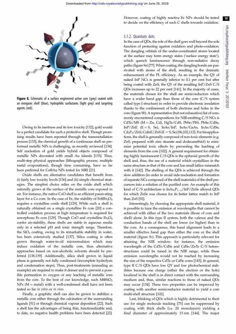
Figure 8. Schematic of a surface engineered active core (grey) coated withan inorganic shell (blue), hydrophilic surfactants (light grey) and targetingagents (red).
rsfs.royalsocietypublishing.orgInterface
Focus3:20120103
10
on June 26, 2018http://rsfs.royalsocietypublishing.org/Downloaded from
Owing to its inertness and its low toxicity [132], gold would
be a perfect candidate for such a protective shell. Though prom-
ising results have been reported through the transmetallation
process [133], the chemical growth of a continuous shell on pre-
formed metallic NPs is challenging, as recently reviewed [134].
Self nucleation of gold yields hybrid objects composed of
metallic NPs decorated with small Au islands [135]. Thus,
multi-step physical approaches (lithographic process, multiple
metal evaporations), though time consuming, have so far
been preferred for Co@Au NPs tested for MRI [21].
Oxide shells are alternative candidates that benefit from
(i) fairly low toxicity levels [136] and (ii) simple chemical strat-
egies. The simplest choice relies on the oxide shell which
naturally grows at the surface of the metallic core exposed in
air. For instance, the native CoO shell is an efficient passivating
layer for a Co core. In the case of Fe, the stability of Fe@Fe3O4
requires a crystalline oxide shell [129]. While such a shell is
naturally obtained on a single crystalline Fe core [20] a con-
trolled oxidation process at high temperature is required for
amorphous Fe core [129]. Though CoO and crystalline Fe3O4
confer air-stability, these shells are stable in aqueous media
only in a selected pH and ionic strength range. Therefore,
the SiO2 coating, owing to its remarkable stability in water,
has been extensively studied [137]. Silica coating is often
grown through water-in-oil microemulsion which may
induce oxidation of the metallic core, thus alternative
approaches based on non-alcoholic solvents should be pre-
ferred [138,139]. Additionally, silica shell grown in liquid
phase is generally not fully condensed (incomplete hydrolysis
and condensation steps). Thus, post-treatments (annealing as
example) are required to make it denser and to prevent a poss-
ible permeation to oxygen or any leaching of metallic ions
from the core. To the best of our knowledge, such M@SiO2
NPs (M¼metal) with a well-condensed shell have not been
tested so far in vitro or in vivo.
Finally, a graphitic shell can also be grown to stabilize a
metallic core either through the calcination of the surrounding
ligands [51] or through chemical vapour deposition [22]. Such
a shell has the advantages of being thin, functionalizable and,
to date, no negative health problems have been detected [22].
However, coating of highly reactive Fe NPs should be tested
to decide on the efficiency of such C shells towards oxidation.
5.1.2. Quantum dotsIn the case of QDs, the role of the shell goes well beyond the sole
function of protecting against oxidation and photo-oxidation.
The dangling orbitals of the under-coordinated atoms located
at the surface may form energy states (‘surface energy state’),
which quench luminescence through non-radiative decay
paths (figure 9a) [77]. When coating, the dangling bonds are pas-
sivated with atoms of the shell, resulting in the dramatic
enhancement of the PL efficiency. As an example, the QY of
naked InP NCs is generally inferior to 0.1 per cent but after
being coated with ZnS, the QY of the resulting InP/ZnS C/S
QDs increases up to 22 per cent [141]. In the majority of cases,
the materials chosen for the shell are semiconductors which
have a wider band gap than those of the core (C/S system
called type I structure) in order to provide electronic insulation
thanks to the confinement of both electrons and holes in the
core (figure 9b). A representative (but not exhaustive) list of com-
monly encountered compositions for NIR-emitting C/S NCs is
CdTe/MS (M ¼ Zn, Cd), HgTe/CdS, PbSe/PbS, PbSe/CdSe,
InP/ZnE (E¼ S, Se), InAs/InP, InAs/GaAs, InAs/CdSe,
Cd3P2/ZnS, CuInE/ZnS (E¼ S, Se) [96,102,112]. For bioapplica-
tions, the shell is generally composed of non-toxic elements (e.g.
ZnS, prepared with zinc stearate and dodecanethiol) to mini-
mize potential toxic effects by preventing the leaching of
elements from the core [102]. A general requirement for obtain-
ing highly luminescent C/S QDs is the epitaxial growth of the
shell and, thus, the use of a material which crystallizes in the
same structure as that of the core and has small lattice mismatch
with it [142]. The shelling of the QDs is achieved through the
slow addition (in order to avoid side-nucleation and formation
of separate NCs composed of the shell materials) of the shell pre-
cursors into a solution of the purified core. An example of this
kind of C/S architecture is InAsxP12x/InP/ZnSe alloyed QDs
for which ZnSe was chosen for its better lattice match to InP
than ZnS [92].
Interestingly, by choosing the appropriate shell material, it
is possible to tune the emission at wavelengths that cannot be
achieved with either of the two materials (those of core and
shell) alone. In this type II system, both the valence and the
conduction bands of the shell are lower (or higher) than in
the core. As a consequence, this band alignment leads to a
smaller effective band gap than either the core or the shell
material (figure 9c). This approach is particularly relevant for
attaining the NIR window: for instance, the emission
wavelength of the CdTe/CdSe and CdSe/ZnTe C/S hetero-
structures could be tuned in the NIR range, while these
emission wavelengths would not be reached by increasing
the size of the respective CdTe or CdSe cores [143]. In general,
type II C/S QDs have low QY and low photochemical stab-
ilities because one charge (either the electron or the hole)
localized in the shell is in direct contact with the surrounding
medium and, thus, similar reactions to those of naked QDs
may occur [134]. These two properties can be improved by
coating with another semiconductor material to yield a core
multi-shell structure [102].
Last, blinking of QDs which is highly detrimental to their
use for single molecule tracking [75] can be suppressed by
coating with thick shells (i.e. 20 monolayers) yielding a
final diameter of approximately 15 nm [144]. The major

surface(a) (b) (c)
surface energystates
interface
CB1
VB1
CB1
VB1
CB1CB2
VB1
VB2
sem1 sem1
hc/l1 = Eg1hc/l2 = Eg12 < Eg1
,Eg2
sem2
sem1 sem2
core type I core/shell type II core/shell
Eg1 Eg1l1
l2Eg1Eg2
Eg2 Eg12
interface
Figure 9. Core (a) type I, (b) and type II core-shell, (c) band edge alignments at the surface and the heterointerface between two semiconductors. In the type Istructure, both the electron and the hole localize within the material with a narrower energy gap, which is semiconductor 1 (sem1) in the present case. As a result,the wavelength emission, l1, is determined by Eg1. The energy gradient existing in the type II structure tends to spatially separate the electron and the hole ondifferent sides of the heterointerface. In this case, the wavelength emission l2 is determined by the energy difference between the conduction band edge of sem1and the valence band edge of semiconductor 2 (sem2), and hence, it is lower than the band gap of either semiconductor. (Adapted from [140]. Copyright & 2012American Chemical Society.) (Online version in colour.)
Figure 10. Schematic of the three generic strategies for water transfer of hydrophobic NPs: through ligand exchange or copolymer addition. (Online version in colour.)
rsfs.royalsocietypublishing.orgInterface
Focus3:20120103
11
on June 26, 2018http://rsfs.royalsocietypublishing.org/Downloaded from
drawback is the large size, which may be inappropriate for
the observation of molecular phenomenon [75], but this pro-
blem has been shown to be possibly circumvented when a
composition-graded interface exists between the core and
the shell in the more compact (8 nm) CdSe/ZnSe QDs [145].
5.2. Phase transfer and surface modification5.2.1. Phase transfer, water stability, stealthPhase transfer becomes an important issue once optimized
functional NPs have been prepared in organic solvent;
different strategies have already been reviewed [146,147]
and can be divided, in a first approximation, between two
generic approaches (figure 10):
— ligand exchange: hydrophobic surfactants are replaced by a
bifunctional ligand presenting at one end, a function hold-
ing a stronger affinity with the NP surface than the initial
ligand and, at the other side, a hydrophilic ending. To
enhance the binding affinity and favour a complete replace-
ment of the hydrophobic surfactants, polydendate ligands,
such as dimercaptosuccinic acid (DMSA), are often used
[16]. This ligand exchange approach is particularly useful
to stabilize water-soluble NPs with small hydrodynamic
size (less than 20 nm), but may lead to particle aggregation
and loss of optical properties for QDs [147]. This problem is
commonly encountered for C/S QDs such as CdSe/ZnS
[148]. InP/ZnS [149] or the other NIR-emitting material
CuInS2/ZnS [150]. Recently, Reiss and co-workers [150]
have given insight on the precise mechanism, attributing
the quenching to hole transfer from the QDs to the capping
ligand (cysteine) resulting in the formation of the cysteine
dimer (cystine); and
— copolymer addition: amphiphilic surfactants are added,
their hydrophobic tails form weak interactions with the
existing hydrophobic coating while their hydrophilic

rsfs.royalsocietypublishing.orgInterface
Focus3:20120103
12
on June 26, 2018http://rsfs.royalsocietypublishing.org/Downloaded from
groups are exposed, ensuring water-solubility. A variety
of lipophilic polyethylene glycol (PEG)-based polymers
has been used [147]. Such copolymer strategy leads to a
drastic increase in the hydrodynamic size of the NPs
(greater than 20 nm) but ensures fairly long blood
circulation due to PEG moities [151].
The choice of functionalization strategy results from a deli-
cate balance between the surface state chemistry of the NPs and
the final hydrodynamic diameter reached. Hydrodynamic size
influences the relaxivity constant and drives the interactions
with tissues and biological media (through size-dependent dif-
fusion). While ultra-small particles (ca 5 nm) are quickly
excreted by the kidney, intermediate NPs (15–100 nm) exhibit
longer circulation time [152], larger NPs (greater than 100 nm)
being more susceptible to opsonization (uptake by the
immune defence system). Thus, the functionalization strategy
must be carefully chosen in order to reach the optimized
window of hydrodynamic size (15–100 nm).
In addition to the hydrodynamic size effect, the pharma-
cokinetics and biodistribution of NPs is driven by surface
coating. Lifetime in blood circulation strongly depends on
the interaction of the NPs with plasma proteins (opsonins).
Accumulations of opsonins are recognized by the reticuloen-
dothelial system, and phagocytosis by macrophage grafting
of PEG on the surface of NPs may inhibit protein interaction
and prolong blood circulation time [153]. This effect strongly
depends on the conformation of the PEG chains at the NPs
surface, which evolves from mushroom to brush configur-
ations for longer PEG chain (greater than or equal to
2000 Da) and higher surface density [153]. While brush con-
figurations generate greater protein repulsion, it may also
lower the NP targeting efficiency due to steric shielding of
the specific agents [154]. Therefore, targeting agents should
be conjugated to a PEG-spacer of similar length to stand at
the outmost exterior of the NPs, lying above the organic
corona [153].
5.2.2. Cancer cell targetingNumerous reports have shown that most NPs accumulate in
tumours due to enhanced permeation and retention (EPR)
effect, which results from relatively large and permea-
ble blood vessels along with poor lymphatic drainage of
tumour cells [153]. For instance, iron oxide NPs were success-
fully used to diagnose cancer without any targeting agents
[155]. Such a cancer cell uptake strategy is referred to as pas-
sive targeting and let us consider the possibility of universal
labelling. Charged NPs have been tested for universal label-
ling but controversial results have been found. While
anionic NPs (citrate) have been reported as exhibiting a
better cell uptake than cationic or uncharged NPs [156],
another study shows that cationic (aminodextran) NPs were
optimized [157]. Though contradictory, these results might
be explained by the tendency of charged NPs to be destabi-
lized under harsh pH and ionic strength environments, as
encountered in biological media.
In order to enhance the selective internalization of NPs,
active targeting strategies were developed. Driven to the
vicinity of tumour cells by EPR effect, NP grafted with ade-
quate moieties would be internalized faster through
receptor-mediated endocytosis. Such tumour surrounding
clearance generates a diffusion gradient which can favour
further NP flow, and, thus, the accumulation of NP within
the tumour region [153]. One of the main challenges of
active targeting is the design of adequate targeting moieties.
Indeed, tumour cells exhibit receptors fairly similar to the
surrounding healthy cells, the difference being their relative
abundance. Therefore, targeting agents must specifically
bind to overexpressed receptors. Small molecules, peptides,
proteins, aptamers and antibodies have demonstrated high
affinity with receptors overexpressed in malignant cells as
previously reviewed [2,30,153]. A key issue during the graft-
ing of such moieties onto the NP surface is to maintain their
affinity for receptors. Their density, accessibility and confor-
mation should be preserved; thus, spacers are often added
to avoid shielding and denaturing of the ligand.
6. ApplicationsIn this part, we aim to illustrate the recent progress in MRI
and NIR in vivo real-time imaging due to the use of the
new generation of magnetic NPs and QDs. The last part
will aim to present the recent very first attempts to combine
of both properties in multi-modal single nano-objects and
the promises of this strategy.
6.1. Magnetic resonance imaging in vivoIn this part, we aim to illustrate the recent progress in in vivoMRI due to the use of the new generation of magnetic NPs.
The main objective is to evaluate the potentialities of the
latter to favour further developments in this field of appli-
cation. Reviews on MRI using ‘classical’ MNPs (SPIO and
USPIO) can be referred to for comparison purposes; they gen-
erally describe in vivo MRI experiments dealing with cancer,
cardiovascular disease or molecular imaging [158]. Here, we
only report examples of MRI improvements due to new con-
trast agents. Moreover, we would like to mention studies that
directly compare MNPs whose magnetic materials were of
different nature, but coating and functionalization were iden-
tical. This way, the other parameters that necessarily impact
the MRI response (coating thickness, bio-distribution, etc.)
can be considered unchanged.
As previously explained, the main reason for working on
magnetic composition of contrast agents is to enhance
contrast on MR images. In a recent study reported by
Cheong et al. [19], it was shown that Fe/FeOx core/shell
NPs improve by a factor 2 the contrast in T2-weighted MR
images of mice nodes compared with pure FeOx NPs. Inter-
estingly, they allow for a much better in vivo detection
of small tumours (1–3 mm) at 1.5 T [19]. In vivo probing of
small cancers (approx. 50 mg) with manganese ferrite NPs
coated with DMSA and conjugated with the cancer-
targeting antibody Herceptin was also successful, as reported
by Cheon’s group [16]. In contrast, the analogue pure iron
oxide NPs did not allow such performances. The authors
attribute this promising result to the higher saturation mag-
netization of the manganese ferrite NPs. Developed by
Chen et al., the 12 nm FePt NPs conjugated to the anti-Her2
monoclonal antibody showed significant contrast enhance-
ment in both MRI and CT, thus taking advantage of their
magnetic properties and the high X-ray absorption of plati-
num [159]. Indeed, 24 h after injection (28 mM Fe
concentration, 100 ml) into mice bearing transplanted MBT2
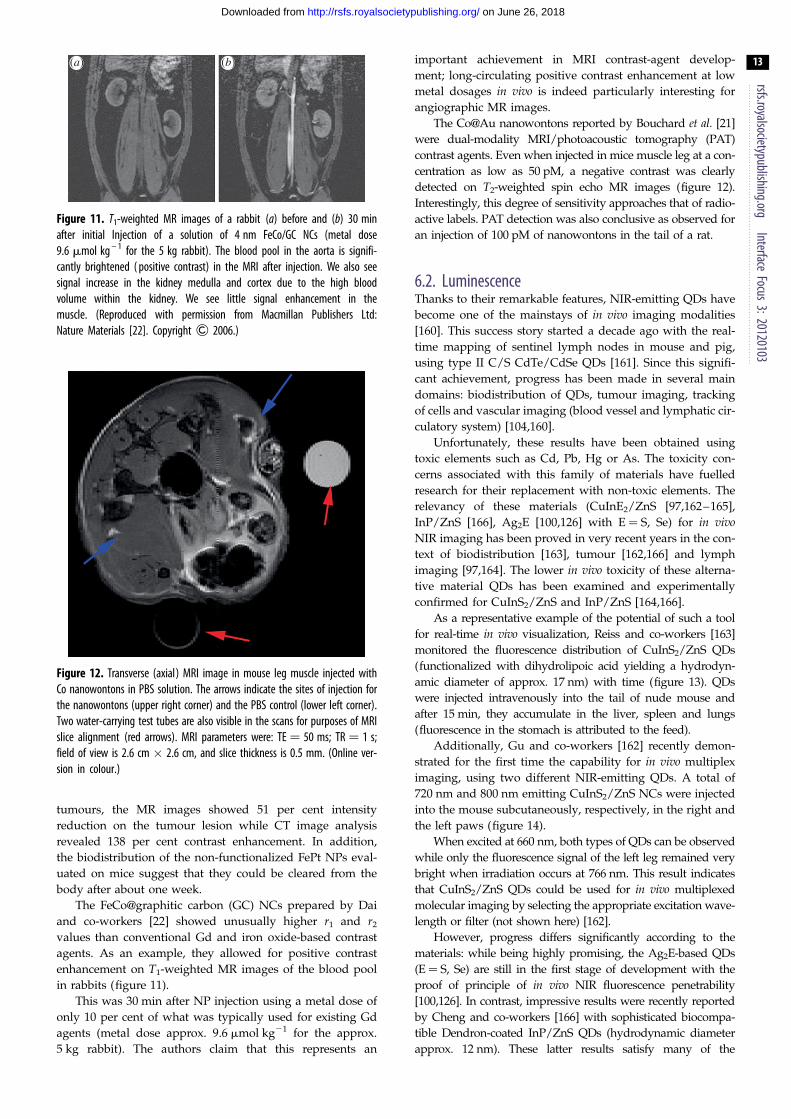
Figure 12. Transverse (axial) MRI image in mouse leg muscle injected withCo nanowontons in PBS solution. The arrows indicate the sites of injection forthe nanowontons (upper right corner) and the PBS control (lower left corner).Two water-carrying test tubes are also visible in the scans for purposes of MRIslice alignment (red arrows). MRI parameters were: TE ¼ 50 ms; TR ¼ 1 s;field of view is 2.6 cm � 2.6 cm, and slice thickness is 0.5 mm. (Online ver-sion in colour.)
(a) (b)
Figure 11. T1-weighted MR images of a rabbit (a) before and (b) 30 minafter initial Injection of a solution of 4 nm FeCo/GC NCs (metal dose9.6 mmol kg – 1 for the 5 kg rabbit). The blood pool in the aorta is signifi-cantly brightened ( positive contrast) in the MRI after injection. We also seesignal increase in the kidney medulla and cortex due to the high bloodvolume within the kidney. We see little signal enhancement in themuscle. (Reproduced with permission from Macmillan Publishers Ltd:Nature Materials [22]. Copyright & 2006.)
rsfs.royalsocietypublishing.orgInterface
Focus3:20120103
13
on June 26, 2018http://rsfs.royalsocietypublishing.org/Downloaded from
tumours, the MR images showed 51 per cent intensity
reduction on the tumour lesion while CT image analysis
revealed 138 per cent contrast enhancement. In addition,
the biodistribution of the non-functionalized FePt NPs eval-
uated on mice suggest that they could be cleared from the
body after about one week.
The FeCo@graphitic carbon (GC) NCs prepared by Dai
and co-workers [22] showed unusually higher r1 and r2
values than conventional Gd and iron oxide-based contrast
agents. As an example, they allowed for positive contrast
enhancement on T1-weighted MR images of the blood pool
in rabbits (figure 11).
This was 30 min after NP injection using a metal dose of
only 10 per cent of what was typically used for existing Gd
agents (metal dose approx. 9.6 mmol kg21 for the approx.
5 kg rabbit). The authors claim that this represents an
important achievement in MRI contrast-agent develop-
ment; long-circulating positive contrast enhancement at low
metal dosages in vivo is indeed particularly interesting for
angiographic MR images.
The Co@Au nanowontons reported by Bouchard et al. [21]
were dual-modality MRI/photoacoustic tomography (PAT)
contrast agents. Even when injected in mice muscle leg at a con-
centration as low as 50 pM, a negative contrast was clearly
detected on T2-weighted spin echo MR images (figure 12).
Interestingly, this degree of sensitivity approaches that of radio-
active labels. PAT detection was also conclusive as observed for
an injection of 100 pM of nanowontons in the tail of a rat.
6.2. LuminescenceThanks to their remarkable features, NIR-emitting QDs have
become one of the mainstays of in vivo imaging modalities
[160]. This success story started a decade ago with the real-
time mapping of sentinel lymph nodes in mouse and pig,
using type II C/S CdTe/CdSe QDs [161]. Since this signifi-
cant achievement, progress has been made in several main
domains: biodistribution of QDs, tumour imaging, tracking
of cells and vascular imaging (blood vessel and lymphatic cir-
culatory system) [104,160].
Unfortunately, these results have been obtained using
toxic elements such as Cd, Pb, Hg or As. The toxicity con-
cerns associated with this family of materials have fuelled
research for their replacement with non-toxic elements. The
relevancy of these materials (CuInE2/ZnS [97,162–165],
InP/ZnS [166], Ag2E [100,126] with E ¼ S, Se) for in vivoNIR imaging has been proved in very recent years in the con-
text of biodistribution [163], tumour [162,166] and lymph
imaging [97,164]. The lower in vivo toxicity of these alterna-
tive material QDs has been examined and experimentally
confirmed for CuInS2/ZnS and InP/ZnS [164,166].
As a representative example of the potential of such a tool
for real-time in vivo visualization, Reiss and co-workers [163]
monitored the fluorescence distribution of CuInS2/ZnS QDs
(functionalized with dihydrolipoic acid yielding a hydrodyn-
amic diameter of approx. 17 nm) with time (figure 13). QDs
were injected intravenously into the tail of nude mouse and
after 15 min, they accumulate in the liver, spleen and lungs
(fluorescence in the stomach is attributed to the feed).
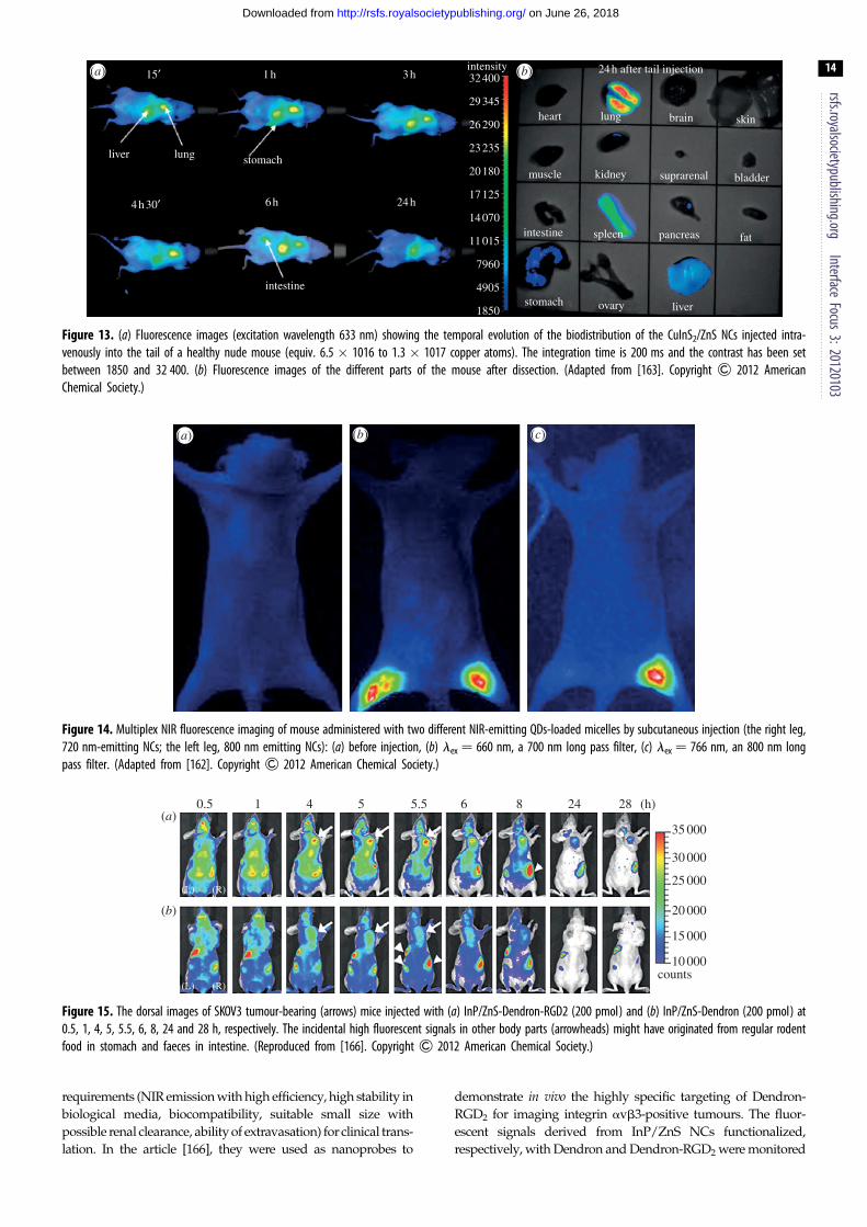
Additionally, Gu and co-workers [162] recently demon-
strated for the first time the capability for in vivo multiplex
imaging, using two different NIR-emitting QDs. A total of
720 nm and 800 nm emitting CuInS2/ZnS NCs were injected
into the mouse subcutaneously, respectively, in the right and
the left paws (figure 14).
When excited at 660 nm, both types of QDs can be observed
while only the fluorescence signal of the left leg remained very
bright when irradiation occurs at 766 nm. This result indicates
that CuInS2/ZnS QDs could be used for in vivo multiplexed
molecular imaging by selecting the appropriate excitation wave-
length or filter (not shown here) [162].
However, progress differs significantly according to the
materials: while being highly promising, the Ag2E-based QDs
(E¼ S, Se) are still in the first stage of development with the
proof of principle of in vivo NIR fluorescence penetrability
[100,126]. In contrast, impressive results were recently reported
by Cheng and co-workers [166] with sophisticated biocompa-
tible Dendron-coated InP/ZnS QDs (hydrodynamic diameter
approx. 12 nm). These latter results satisfy many of the
(a) (b) (c)
Figure 14. Multiplex NIR fluorescence imaging of mouse administered with two different NIR-emitting QDs-loaded micelles by subcutaneous injection (the right leg,720 nm-emitting NCs; the left leg, 800 nm emitting NCs): (a) before injection, (b) lex ¼ 660 nm, a 700 nm long pass filter, (c) lex ¼ 766 nm, an 800 nm longpass filter. (Adapted from [162]. Copyright & 2012 American Chemical Society.)
0.5(a)
(b)
(L) (R)
(L) (R)
1 4 5 5.5 6 8 24 28 (h)
35 000
30 000
25 000
20 000
15 000
10 000counts
Figure 15. The dorsal images of SKOV3 tumour-bearing (arrows) mice injected with (a) InP/ZnS-Dendron-RGD2 (200 pmol) and (b) InP/ZnS-Dendron (200 pmol) at0.5, 1, 4, 5, 5.5, 6, 8, 24 and 28 h, respectively. The incidental high fluorescent signals in other body parts (arrowheads) might have originated from regular rodentfood in stomach and faeces in intestine. (Reproduced from [166]. Copyright & 2012 American Chemical Society.)
15¢
liver lung stomach
intestine
intensity32 400
29 345
26 290
23 235
20 180
17 125
14 070
11 015
7960
4905
1850stomach ovary liver
fatpancreasspleenintestine
muscle
heart lung brain skin
24 h after tail injection
kidney suprarenal bladder
6 h 24 h4 h 30¢
1 h 3 h(a) (b)
Figure 13. (a) Fluorescence images (excitation wavelength 633 nm) showing the temporal evolution of the biodistribution of the CuInS2/ZnS NCs injected intra-venously into the tail of a healthy nude mouse (equiv. 6.5 � 1016 to 1.3 � 1017 copper atoms). The integration time is 200 ms and the contrast has been setbetween 1850 and 32 400. (b) Fluorescence images of the different parts of the mouse after dissection. (Adapted from [163]. Copyright & 2012 AmericanChemical Society.)
rsfs.royalsocietypublishing.orgInterface
Focus3:20120103
14
on June 26, 2018http://rsfs.royalsocietypublishing.org/Downloaded from
requirements (NIR emission with high efficiency, high stability in
biological media, biocompatibility, suitable small size with
possible renal clearance, ability of extravasation) for clinical trans-
lation. In the article [166], they were used as nanoprobes to
demonstrate in vivo the highly specific targeting of Dendron-
RGD2 for imaging integrin avb3-positive tumours. The fluor-
escent signals derived from InP/ZnS NCs functionalized,
respectively, with Dendron and Dendron-RGD2 were monitored

rsfs.royalsocietypublishing.orgInterface
Focus3:20120103
15
on June 26, 2018http://rsfs.royalsocietypublishing.org/Downloaded from
in real-time over 28 h (figure 15). Thanks to the high sensitivity of
these QDs, the difference of behaviour induced by the different
functionalization could be evidenced. In the case of Dendron-
RGD2 functionalization, long-term retention is clearly observed
from the fluorescence signal at the tumour site (indicated by
the arrow, figure 15) which carries on after 28 h. In contrast,
tumour uptake of InP/ZnS QDs-Dendron with visible contrast
from surrounding tissues can be observed between 4 and 6 h
and then disappears. This behaviour was assigned to the
enhanced permeability and retention (EPR) effect for the suitably
small InP/ZnS QDs-Dendron.
6.3. Multi-modalRecently, hybrid NPs combining at least two properties have
received lots of interest, as shown by the increasing number
of dedicated reviews [167,168]. Combining optic and mag-
netic properties within the same nano-object would open
new perspectives towards multi-modal imaging (NIR and
MRI) [169], and theranostic applications, coupling detection
and treatment potentialities [170]. However, one of the
main issues is to keep both physical properties unaltered.
QD luminescence can be strongly reduced due to electron
transfer and competitive light absorption with the magnetic
material. The direct growth of QD onto magnetic NPs, form-
ing FePt-QDs heterodimers [171] or FePt@CdSe core/shell
structure [172], results in a prominent quenching of the fluor-
escence [173]. Analogously, the growth of Co tips onto
preformed CdSe nanorods results in an emission intensity
30 times lower than that of pure CdSe rods [174].
To prevent electron transfer, which results in luminescence
quenching, QD and magnetic material could be isolated. One
strategy is based on the use of metal oxide, insulating material,
as the magnetic component of the heterodimer. Gao et al. [175]
have shown that Fe3O4-CdSe NPs exhibit quantum yield as
high as 38 per cent. Such fluorescence enables the intracellular
detection of the NPs; however, no results were reported
regarding their magnetic properties nor their relaxivity. In
order to favour metallic materials, which exhibit higher mag-
netization, a solution consists in incorporating preformed
magnetic NPs and QDs into an isolating matrix (such as
silica) [176]. However, the resulting object exhibits a high
hydrodynamic volume, which may be a drawback for further
in vivo applications and prevents the diffusion of water proton
in the vicinity of the magnetic NPs, resulting in poor relaxivity
[177]. Deka et al. [178] have reported a promising approach
based on the intercalation of a semiconductor with a larger
band gap between the metallic part and the QD, which may
result in decoupling QD and metal electronic states.
CdSe@CdS decorated with Co tips exhibited preserved mag-
netic properties (MS ¼ 148 emu/gCo) but partially quenched
fluorescence (QY¼ 3%). Optimization of the spacer nature
and thickness could be pursued to retain both physical
properties unaltered.
7. ConclusionIn this review paper, we have presented the potentiality of a
new generation of optimized contrast agents, based on met-
allic NPs and Hg, Cd, Pb, As free QDs, for, respectively,
MRI and NIR imaging. Though extensive literature can be
found on well-established iron oxide NPs or Cd-based QDs,
only a few reports outline the requirements that the new
probe generation should fulfil. Thanks to the description of
the physics of the imaging techniques, optimized materials
could be illuminated for as long as the syntheses appropriate
to the corresponding NPs. Surface engineering strategies to
ensure the biodistribution and the specific targeting of
inorganic NPs were reviewed. The resulting NPs combine,
through a complex architecture: the optimized inorganic
core surrounded by a non-porous coating shell, to ensure
the stability of the core, an organic corona to reach adequate
biodistribution and targeting moities to enhance the specific
cellular uptake. Few results demonstrate the in vivo potential-
ity of these new generations of probes. Drastic enhancement
of relaxivity (up to 105 times) was observed for Co-based
NPs, while impressive fluorescent results were obtained for
Cd-free InP/ZnS QDs. The next step towards the optimiz-
ation of contrast agents relies on the integration, within a
single object, of MRI and NIR imaging potentialities. Such
multi-modal NPs, though extremely promising, require the
strict decoupling of semiconducting and metallic electronic
states. The introduction of a large gap semiconductor
spacer could be the most promising approach which could
yield unaltered magnetic and optic properties.
References
1. Cassidy PJ, Radda GK. 2005 Molecular imagingperspectives. J. R. Soc. Interface 2, 133 – 144.(doi:10.1098/rsif.2005.0040)
2. Cho EC, Glauss C, Chen J, Welch MJ, Xia Y. 2010Inorganic nanoparticle-based contrast agents formoleuclar imaging. Trends Mol. Med. 16, 561 – 573.(doi:10.1016/j.molmed.2010.09.004)
3. Lee D-E, Koo H, Sun I-C, Ryu JH, Kim K, Kwon IC.2012 Multifunctional nanoparticles for multimodalimaging and theragnosis. Chem. Soc. Rev. 41,2656 – 2672. (doi:10.1039/c2cs15261d)
4. Hotzer B, Medintz IL, Hildebrandt N. 2012Fluorescence in nanobiotechnology: sophisticatedfluorophores for novel applications. Small 8,2297 – 2326. (doi:10.1002/smll.201200109)
5. Lacroix L-M, Ho D, Sun S. 2010 Recent advances inmagnetic nanoparticles for diagnostic andtherapeutic applications. Curr. Top. Med. Chem. 10,1184 – 1197.
6. Finney EE, Finke RG. 2008 Nanocluster nucleationand growth kinetic and mechanistic studies: areview emphasizing transitionmetal nanoclusters.J. Colloid Interface Sci. 317, 351 – 374. (doi:10.1016/j.jcis.2007.05.092)
7. LaMer VK, Dinegra RH. 1950 Theory, production andmechanism of formation of monodispersedhydrosols. J. Am. Chem. Soc. 72, 4847 – 4854.(doi:10.1021/ja01167a001)
8. Park J, Joo J, Kwon SG, Jang Y, Hyeon T. 2007Synthesis of monodisperse spherical nanocrystals.
Angew. Chem. Int. Ed. 46, 4630 – 4660. (doi:10.1002/anie.200603148)
9. Shevchenko EV, Talapin DT, Schnablegger H,Kornowski A, Festin O, Svedlinh P, Haase M, WellerH. 2002 Study of nucleation and growth in theorganometallic synthesis of magnetic alloynanocrystals: the role of nucleation rate in sizecontrol of CoPt3 nanocrystals. J. Am. Chem. Soc.125, 9090 – 9101. (doi:10.1021/ja029937l)
10. Lin W, Hyeon T, Lanza GM, Zhang M, Maede TJ.2009 Magnetic nanoparticles for early detection ofcancer by magnetic resonance imaging. MRS Bull.34, 441 – 448. (doi:10.1557/mrs2009.120)
11. Caravan P, Ellison JL, McMurry TJ, Lauffer RB. 1999Gadolinium(III) chelates as MRI contrast agents:

rsfs.royalsocietypublishing.orgInterface
Focus3:20120103
16
on June 26, 2018http://rsfs.royalsocietypublishing.org/Downloaded from
structure, dynamics and applications. Chem. Rev.99, 2293 – 2352. (doi:10.1021/cr980440x)
12. Caravan P. 2006 Strategies for increasing thesensitivity of gadolinium based MRI contrast agents.Chem. Soc. Rev. 35, 512 – 523. (doi:10.1039/B510982P)
13. De Leon-Rodriguez LM, Lubag AJM, Malloy CR,Martinez GV, Gillies RJ, Sherry AD. 2011 ResponsiveMRI agents for sensing metabolism in vivo. Acc.Chem. Res. 42, 948 – 957. (doi:10.1021/ar800237f )
14. Na HB, Song IC, Hyeon T. 2009 Inorganicnanoparticles for MRI contrast agents. Adv. Mater.21, 2133 – 2148. (doi:10.1002/adma.200802366)
15. Cheon J, Lee J-H. 2008 Synergistically integratednanoparticles as multimodal probes fornanobiotechnology. Acc. Chem. Res. 41,1630 – 1640. (doi:10.1021/ar800045c)
16. Lee J-H et al. 2007 Artificially engineered magneticnanoparticles for ultra-sensitive molecular imaging.Nat. Med. 13, 95 – 99. (doi:10.1038/nm1467)
17. Duan H, Kuang M, Wang X, Wang YA, Mao H, Nie S.2008 Reexamining the effects of particle size andsurface chemistry on the magnetic properties of ironoxide nanocrystals: new insights into spin disorderand proton relaxivity. J. Phys. Chem. C 112,8127 – 8131. (doi:10.1021/jp8029083)
18. Hadjipanayis CG, Bonder MJ, Balakrishnan S, WangX, Mao H, Hadjipanayis GC. 2008 Metallic ironnanoparticles for MRI contrast enhancement andlocal hyperthermia. Small 4, 1925 – 1929. (doi:10.1002/smll.200800261)
19. Cheong S et al. 2011 Simple synthesis andfunctionalization of iron nanoparticles for magneticresonance imaging. Angew. Chem. Int. Ed. 50,4206 – 4209. (doi:10.1002/anie.201100562)
20. Lacroix L-M, Huls NF, Ho D, Sun X, Cheng K, Sun S.2011 Stable single-crystalline body centered cubicFe nanoparticles. Nano Lett. 11, 1641 – 1645.(doi:10.1021/nl200110t)
21. Bouchard L-S, Anwar MS, Liu GL, Hann B, Xie ZH,Gray JW, Wang X, Pines A, Chen FF. 2009 Picomolarsensitivity MRI and photoacoustic imaging of cobaltnanoparticles. Proc. Nat Acad. Soc. USA 106, 4085 –4089. (doi:10.1073/pnas.0813019106)
22. Seo WS et al. 2006 FeCo/graphitic-shell nanocrystalsas advanced magnetic-resonance-imaging and near-infrared agents. Nat. Mater. 5, 971 – 976. (doi:10.1038/nmat1775)
23. Maesono S, Suzuki T, Saita S. 2008Superparamagnetic FePt nanoparticles as excellentMRI contrast agents. J. Magn. Magn. Mater. 320,L79 – L83. (doi:10.1016/j.jmmm.2008.01.026)
24. Tromsdorf UI et al. 2007 Size and surface effects onthe MRI relaxivity of manganese ferrite nanoparticlecontrast agents. Nano Lett. 7, 2422 – 2427. (doi:10.1021/nl071099b)
25. Lee N, Choi Y, Lee Y, Park M, Moon WK, Choi SH,Hyeon T. 2012 Water-dispersible ferromagnetic ironoxide nanocubes with extremely high r2 relaxivityfor highly sensitive in vivo MRI of tumors. NanoLett. 12, 3127 – 3131. (doi:10.1021/nl3010308)
26. Lee JS, Tan RP, Wu JH, Kim YK. 2011 Effect ofinterparticle interactions and size dispersion in
magnetic nanoparticle assemblies: a static anddynamic study. Appl. Phys. Lett. 99, 062506.(doi:10.1063/1.3624833)
27. Yang Y, Liu X-L, Yi J-B, Yang Y, Fan H-M, Ding J.2012 Stable vortex magnetite nanorings colloid:micromagnetic simulation and experimentaldemonstration. J. Appl. Phys. 111, 044303.(doi:10.1063/1.3684963)
28. Snoeck E, Gatel C, Lacroix L-M, Blon T, Lachaize S,Carrey J, Respaud M, Chaudret B. 2008 Magneticconfigurations of 30 nm iron nanocubes studied byelectron holography. Nano Lett. 8, 4293 – 4298.(doi:10.1021/nl801998x)
29. Lacroix L-M, Lachaize S, Hue F, Gatel C, Blon T, TanRP, Carrey J, Warot-Fonrose B, Chaudret B. 2012Stabilization vortices in interacting nano-objects:a chemical approach. Nano Lett. 12, 3245 – 3250.(doi:10.1021/nl3012616)
30. Yang F, Jin C, Subedi S, Lee CL, Wang Q, Jiang Y,Li J, Di Y, Fu D. 2012 Emerging inorganicnanomaterials for pancreatic cancer diagnosis andtreatment. Cancer Treat. Rev. 38, 566 – 579. (doi:10.1016/j.ctrv.2012.02.003)
31. Huang S-H, Juang R-S. 2011 Biochemical andbiomedical applications of multifunctional magneticnanoparticles: a review. J. Nanopart. Res. 13,4411 – 4430. (doi:10.1007/s11051-011-0551-4)
32. Huang S, Yan W, Hu G, Wang L. 2012 Facileand green synthesis of biocompatible andbioconjugatable magnetite nanofluids for high-resolution T2 MRI contrast agents. J. Phys. Chem. C116, 20 558 – 20 563. (doi:10.1021/jp305211d)
33. Laurent S, Forge D, Port M, Roch A, Robic C, VanderElst L, Muller RN. 2008 Magnetic iron oxidenanoparticles: synthesis, stabilization, vectorization,physicochemical characterizations, and biologicalapplications. Chem. Rev. 108, 2064 – 2110. (doi:10.1021/cr068445e)
34. Park J et al. 2005 One-nanometer-scale size-controlled synthesis of monodisperse magnetic ironoxide nanoparticles. Angew. Chem. Int. Ed. 44,2872 – 2877. (doi:10.1002/anie.200461665)
35. Sun S, Zeng H. 2002 Size-controlled synthesis ofmagnetite nanoparticles. J. Am. Chem. Soc. 124,8204 – 8205. (doi:10.1021/ja026501x)
36. Reddy LH, Arias JL, Nicolas J, Couvreur P. 2012Magnetic nanoparticles: design and characterization,toxicity and biocompatibility, pharmaceutical andbiomedical applications. Chem. Rev. 112,5818 – 5878. (doi:10.1021/cr300068p)
37. Lee N, Hyeon T. 2012 Designed synthesis ofuniformly sized iron oxide nanoparticles for efficientmagnetic resonance imaging contrast agents. Chem.Soc. Rev. 41, 2575 – 2589. (doi:10.1039/C1CS15248C)
38. Sun S, Zeng H, Robinson DB, Raoux S, Rice PM,Wang SX, Li G. 2004 Monodisperse MFe2O4 (M¼Fe, Co, Mn) nanoparticles. J. Am. Chem. Soc. 126,273 – 279. (doi:10.1021/ja0380852)
39. Farrell D, Majetich SA, Wilcoxon JP. 2003Preparation and characterization of monodisperseFe nanoparticles. J. Phys. Chem. B 107, 11 022 –11 030. (doi:10.1021/jp0351831)
40. Pei W, Kakibe S, Ohta I, Takahashi M. 2005Controlled monodisperse Fe nanoparticlessynthesized by chemical method. IEEE Trans. Magn.41, 3391 – 3393. (doi:10.1109/TMAG.2005.855207)
41. Shavel A, Rodriguez-Gonzalez B, Spasova M, FarleM, Liz-Marzan LM. 2007 Synthesis andcharacterization of iron/iron oxide core/shellnanocubes. Adv. Funct. Mater. 17, 3870 – 3876.(doi:10.1002/adfm.200700494)
42. Lacroix L-M, Lachaize S, Falqui A, Respaud M,Chaudret B. 2009 Iron nanoparticle growth inorganic superstructures. J. Am. Chem. Soc. 131,549 – 557. (doi:10.1021/ja805719c)
43. Guo Z, Henry LL, Palshin V, Podlaha EJ. 2006Synthesis of poly(methyl methacrylate) stabilizedcolloidal zero-valence metallic nanoparticles.J. Mater. Chem. 16, 1772 – 1777. (doi:10.1039/b515565g)
44. Puntes VF, Krishnan KM, Alivisatos AP. 2001Colloidal nanocrystal shape and size control: thecase of cobalto. Science 291, 2115 – 2117. (doi:10.1126/science.1057553)
45. Sun S, Murray CB. 1999 Synthesis of monodispersecobalt nanocrystals and their assembly intomagnetic superlattices. J. Appl. Phys. 85,4325 – 4330. (doi:10.1063/1.370357)
46. Soumare Y, Garcia C, Maurer T, Chaboussant G, OttF, Fievet F, Piquemal J-Y, Viau G. 2009 Kineticallycontrolled synthesis of hexagonally close-packedcobalt nanorods with high magnetic coercivity. Adv.Funct. Mater. 19, 1971 – 1977. (doi:10/1002/adfm.200800822)
47. Liakakos N et al. 2012 The big impact of a smalldetail: cobalt nanocrystal polymorphism as a resultof precursor addition rate during stock solutionpreparation. J. Am. Chem. Soc. 134, 17 922 –17 931. (doi:10.1021/ja304487b)
48. Dumestre F, Chaudret B, Amiens C, Respaud M,Fejes P, Renaud P, Zurcher P. 2003 Unprecedentedcrystalline super-lattices of monodisperse cobaltnanorods. Angew. Chem. Int. Ed. 42, 5213 – 5216.(doi:10.1002/anie.200352090)
49. Ogawa T, Takano H, Kura H, Takahashi M. 2012Synthesis of Fe-Co nanoparticles with highsaturation magnetization by low temperature post-annealing. J. Appl. Phys. 111, 07B533. (doi:10.1063/1.3679027)
50. Wang C, Peng S, Lacroix L-M, Sun S. 2009 Synthesisof high magnetic moment CoFe nanoparticles viainterfacial diffusion in core/shell structured Co/Fenanoparticles. Nano Res. 2, 380 – 385. (doi:10.1007/s12274-009-9037-4)
51. Desvaux C, Amiens C, Fejes P, Renaud P, RespaudM, Lecante P, Snoeck E, Chaudret B. 2005Multimillimetre-large superlattices of air-stableiron-cobalt nanoparticles. Nat. Mater. 4, 750 – 753.(doi:10.1038/nmat1480)
52. Chaubey GS, Barcena C, Poudyal N, Rong C, Gao J,Sun S, Liu JP. 2007 Synthesis and stabilizationof FeCo Nanoparticles. J. Am. Chem. Soc. 129,7214 – 7215. (doi:10.1021/ja0708969)
53. Sun S, Murray CB, Weller D, Folks L, Moser A. 2000Monodisperse FePt nanoparticles and ferromagnetic

rsfs.royalsocietypublishing.orgInterface
Focus3:20120103
17
on June 26, 2018http://rsfs.royalsocietypublishing.org/Downloaded from
FePt nanocrystal superlattices. Science 287,1989 – 1992. (doi:10.1126/science.287.5460.1989)
54. Elkins KE, Chaubey GS, Nandwana V, Liu JP. 2008 Anovel approach to synthesis of FePt magneticnanoparticles. J. Nano. Res. 1, 23 – 30. (doi:10.4028/www.scientific.net/JNanoR.1.23)
55. Sun S, Anders S, Thomson T, Baglin JEE, Toney MF,Hamann HF, Murray CB, Terris BD. 2003 Controlledsynthesis and assembly of FePt nanoparticles. J. Phys.Chem. B 107, 5419 – 5425. (doi:10.1021/jp027314o)
56. Huber D. 2005 Synthesis, properties, andapplications of iron nanoparticles. Small 1,482 – 501. (doi:10.1002/smll.200500006)
57. Yang H, Ito F, Hasegawa D, Ogawa T, Takahashi M.2007 Facile large-scale synthesis of monodisperse Fenanoparticles by modest-temperaturedecomposition of iron carbonyl. J. Appl. Phys. 101,09J112. (doi:10.1063/1.2711391)
58. Meffre A, Mehdaoui B, Kelsen V, Fazzini PF, Carrey J,Lachaize S, Respaud M, Chaudret B. 2012 A simplechemical route toward monodisperse iron carbidenanoparticles displaying tunable magnetic andunprecedented hyperthermia properties. Nano Lett.12, 4722 – 4728. (doi:10.1021/nl302160d)
59. Dumestre F, Chaudret B, Amiens C, Renaud P, FejesP. 2004 Superlattices of iron nanocubes synthesizedfrom Fe[N(SiMe3)2]2. Science 303, 821 – 823.(doi:10.1126/science.1092641)
60. Meffre A, Lachaize S, Gatel C, Respaud M, ChaudretB. 2011 Use of long chain amine as a reducingagent for the synthesis of high qualitymonodisperse iron(0) nanoparticles. J. Mater. Chem.21, 13 464 – 13 469. (doi:10.1039/C1JM12127H)
61. Lacroix L-M, Lachaize S, Carrey J, Respaud M,Chaudret B. 2011 Iron nanoparticles with tuneablesizes for hyperthermia applications. L’Act. Chim.351, 28 – 35.
62. Keng PY, Shim I, Korth BD, Douglas JF, Pyun J. 2009Synthesis and self assembly of polymer-coatedferromagnetic nanoparticles. ACS Nano 1, 279 – 292.(doi:10.1021/nn7001213)
63. Osuna J, de Caro D, Amiens C, Chaudret B, Snoeck E,Respaud M, Broto J-M, Fert A. 1996 Synthesis,characterization, and magnetic properties of cobaltnanoparticles from an organometallic precursor.J. Phys. Chem. 100, 14 571 – 14 574. (doi:10.1021/jp961086e)
64. Sun S. 2006 Recent advances in chemical synthesis,self-assembly, and applications of FePtnanoparticles. Adv. Mater. 18, 393 – 403. (doi:10.1002/adma.200501464)
65. Gao J et al. 2008 Multifunctional yolk-shellnanoparticles: a potential MRI contrast andanticancer agent. J. Am. Chem. Soc. 130,11 828 – 11 833. (doi:10.1021/ja803920b)
66. Pansare VJ, Hejazi S, Faenza WJ, Prud’homme RK.2012 Review of long-wavelength optical and nirimaging materials: contrast agents, fluorophores,and multifunctional nano carriers. Chem. Mater. 24,812 – 827. (doi:10.1021/cm2028367)
67. Weissleder R. 2001 A clearer vision for in vivoimaging. Nat. Biotechnol. 19, 316 – 317. (doi:10.1038/86684)
68. Frangioni JV. 2003 In vivo near-infrared fluorescenceimaging. Curr. Opin. Chem. Biol. 7, 626 – 634.(doi:10.1016/j.cbpa.2003.08.007)
69. Resch-Genger U, Grabollel M, Cavaliere-Jaricot S,Nitschke R, Nann T. 2008 Quantum dots versusorganic dyes as fluorescent labels. Nat. Methods 5,763 – 775. (doi:10.1038/nmeth.1248)
70. Berlier JE et al. 2003 Quantitative comparison oflong-wavelength alexa fluor dyes to Cy dyes:fluorescence of the dyes and their bioconjugates.J. Histochem. Cytochem. 51, 1699 – 1712. (doi:10.1177/002215540305101214)
71. Aswathy RG, Yoshida Y, Maekawa T, Kumar DS.2010 Near-infrared quantum dots for deep tissueimaging. Anal. Bioanal. Chem. 397, 1417 – 1435.(doi:10.1007/s00216-010-3643-6).
72. Shan J, Uddi M, Wei R, Yao N, Ju Y. 2010 TheHidden effects of particle shape and criteria forevaluating the upconversion luminescence of thelanthanide doped nanophosphors. J. Phys. Chem. C114, 2452 – 2461. (doi:10.1021/jp908976n).
73. Chatterjee DK, Gnanasammandhan MK, Zhang Y.2010 Small upconverting fluorescent nanoparticlesfor biomedical applications. Small 6, 2781 – 2795.(doi:10.1002/smll.201000418)
74. Luo Z, Yuan X, Yu Y, Zhang Q, Leong DT, Lee JY, Xie J.2012 From aggregation-induced emission of Au(I) –thiolate complexes to ultrabright Au(0)@Au(I)– thiolatecore – shell nanoclusters. J. Am. Chem. Soc. 134,16 662 – 16 670. (doi:10.1021/ja306199p).
75. Baba K, Nishida K. 2012 Single-molecule tracking inliving cells using single quantum dot applications.Theranostics 2, 655 – 667. (doi:10.7150/thno.3890)
76. Alivisatos AP. 1996 Perspectives on the physicalchemistry of semiconductor nanocrystals. J. Phys.Chem. 100, 13 226 – 13 239. (doi:10.1021/jp9535506)
77. Smith AM, Nie S. 2010 Semiconductor nanocrystals:structure, properties, and band gap engineering.Acc. Chem. Res. 43, 190 – 200. (doi:10.1021/ar9001069)
78. de Mello Donega C. 2011 Synthesis and propertiesof colloidal heteronanocrystals. Chem. Soc. Rev. 40,1512 – 1546. (doi:10.1039/c0cs00055h)
79. Bailey RE, Nie S. 2003 Alloyed semiconductorquantum dots: tuning the optical propertieswithout changing the particle size. J. Am. Chem.Soc. 125, 7100 – 7106. (doi:10.1021/ja035000o)
80. Gaponik N, Rogach AL. 2008 Aqueous synthesis ofsemiconductor nanocrystals. In semiconductornanocrystals quantum dots (ed. AL Rogach),pp. 73 – 100. New York, NY: Springer.
81. Xue B, Deng D-W, Cao J, Liu F, Li X, Akers W,Achilefu S, Gu Y-Q. 2012 Synthesis of NAC cappednear infrared-emitting CdTeS alloyed quantum dotsand application for in vivo early tumor imaging.Dalton Trans. 41, 4935 – 4947. (doi:10.1039/c2dt12436j)
82. Pons T, Lequeux N, Mahler B, Sasnouski S, FragolaA, Dubertret B. 2009 Synthesis of near-infrared-emitting, water-soluble CdTeSe/CdZnS core/shellquantum dots. Chem. Mater. 21, 1418 – 1424.(doi:10.1021/cm8027127)
83. Harrison MT, Kershaw SV, Burt MG, Eychmuller A,Weller H, Rogach AL. 2000 Wet chemical synthesis andspectroscopic study of CdHgTe nanocrystals with strongnear-infrared luminescence. Mater. Sci. Eng. B69 – 70,355 – 360. (doi:10.1016/S0921-5107(99)00254-8)
84. Kovalenko MV, Kaufmann E, Pachinger D, Roither J,Huber M, Stangl J, Hesser G, Schaffler F, Heiss W.2006 Colloidal HgTe nanocrystals with widelytunable narrow band gap energies: fromtelecommunications to molecular vibrations. J. Am.Chem. Soc. 128, 3516 – 3517. (doi:10.1021/ja058440j)
85. Cademartiri L, Montanari E, Calestani G, Migliori A,Guagliardi A, Ozin GA. 2006 Size-dependentextinction coefficients of PbS quantum dots. J. Am.Chem. Soc. 128, 10 337 – 10 346. (doi:10.1021/ja063166u).
86. Hines MA, Scholes GD. 2003 Colloidal PbSnanocrystals with size-tunable near-infraredemission: observation of post-synthesis self-narrowing of the particle size distribution. Adv.Mater. 15, 1844 – 1849. (doi:10.1002/adma.200305395)
87. Akhtar J et al. 2011 Controlled synthesis of tunedbandgap nanodimensional alloys of PbSxSe12x.J. Am. Chem. Soc. 133, 5602 – 5609. (doi:10.1021/ja200750s)
88. Moreels I, Lambert K, De Muynck D, Vanhaecke F,Poelman D, Martins JC, Allan G, Hens Z. 2007Composition and size-dependent extinctioncoefficient of colloidal PbSe quantum dots. Chem.Mater. 19, 6101 – 6106. (doi:10.1021/cm071410q)
89. Murphy JE, Beard MC, Norman AG, Ahrenkiel SP,Johnson JC, Yu P, Micic OI, Ellingson RJ, Nozik AJ.2006 PbTe colloidal nanocrystals: synthesis,characterization, and multiple exciton generation.J. Am. Chem. Soc. 128, 3241 – 3247. (doi:10.1021/ja0574973)
90. Xie R, Battaglia D, Peng X. 2007 Colloidal InPnanocrystals as efficient emitters covering blue tonear-infrared. J. Am. Chem. Soc. 128, 15 432 –15 433. (doi:10.1021/ja076363h)
91. Xie R, Peng X. 2009 Synthesis of Cu-doped InPNanocrystals (d-dots) with ZnSe diffusion barrier asefficient and color-tunable NIR emitters. J. Am.Chem. Soc. 131, 10 645 – 10 651. (doi:10.1021/ja903558r)
92. Kim S-W, Zimmer JP, Ohnishi S, Tracy JB, FrangioniJV, Bawendi MG. 2005 Engineering InAsxP12x/InP/ZnSe III-V alloyed core/shell quantum dots for thenear-infrared. J. Am. Chem. Soc. 127, 10 526 –10 532. (doi:10.1021/ja0434331)
93. Xie R, Peng X. 2008 Synthetic scheme for high-quality InAs nanocrystals based on self-focusing andone-pot synthesis of InAs-based core – shellnanocrystals. Angew. Chem. Int. Ed. 47,7677 – 7680. (doi:10.1002/anie.200802867)
94. Xie R, Zhang J, Zhao F, Yang W, Peng X. 2010Synthesis of monodisperse, highly emissive, andsize-tunable Cd3P2 nanocrystals. Chem. Mater. 22,3820 – 3822. (doi:10.1021/cm1008653)
95. Harris DK, Allen PM, Han H-S, Walker BJ, Lee J,Bawendi MG. 2011 Synthesis of cadmium arsenide
rsfs.royalsocietypublishing.orgInterface
Focus3:20120103
18
on June 26, 2018http://rsfs.royalsocietypublishing.org/Downloaded from
quantum dots luminescent in the infrared. J. Am.Chem. Soc. 133, 4676 – 4679. (doi:10.1021/ja1101932)
96. Xie R, Rutherford M, Peng X. 2009 Formation ofhigh-quality I-III-VI semiconductor nanocrystals bytuning relative reactivity of cationic precursors.J. Am. Chem. Soc. 131, 5691 – 5697. (doi:10.1021/ja9005767)
97. Cassette E, Pons T, Bouet C, Helle M, Bezdetnaya L,Marchal F, Dubertret B. 2010 Synthesis andcharacterization of near-infrared Cu-In-Se/ZnS core/shell quantum dots for in vivo imaging. Chem.Mater. 22, 6117 – 6124. (doi:10.1021/cm101881b)
98. Ruddy DA, Johnson JC, Smith ER, Neale NR. 2010Size and bandgap control in the solution-phasesynthesis of near-infrared-emitting germaniumnanocrystals. ACS Nano 4, 7459 – 7466. (doi:10.1021/nn102728u)
99. Lee DC, Pietryga JM, Robel I, Werder DJ, SchallerRD, Klimov VI. 2009 Colloidal synthesis of infrared-emitting germanium nanocrystals. J. Am. Chem. Soc.131, 3436 – 3437. (doi:10.1021/ja809218s)
100. Jiang P, Zhu C-N, Zhang Z-L, Tian Z-Q, Pang D-W.2012 Water-soluble Ag2S quantum dots for near-infrared fluorescence imaging in vivo. Biomaterials33, 5130 – 5135. (doi:10.1016/j.biomaterials.2012.03.059)
101. Yarema M et al. 2011 Infrared emitting andphotoconducting colloidal silver chalcogenidenanocrystal quantum dots from a silylamide-promoted synthesis. ACS Nano 5, 3758 – 3765.(doi:10.1021/nn2001118)
102. Reiss P, Protiere M, Li L. 2009 Core/Shellsemiconductor nanocrystals. Small 5, 154 – 168.(doi:10.1002/smll.200800841)
103. Gaponik N, Hickey SG, Dorfs D, Rogach AL,Eychmuller A. 2010 Progress in the light emission ofcolloidal semiconductor nanocrystals. Small 6,1364 – 1378. (doi:10.1002/smll.200902006)
104. Wang C, Gao X, Su X. 2010 In vitro and in vivoimaging with quantum dots. Anal. Bioanal. Chem.397, 1397 – 1415. (doi:10.1007/s00216-010-3481-6)
105. Murray CB, Norris DJ, Bawendi MG. 1993 Synthesisand characterization of nearly monodisperse CdE(E¼S, Se, Te) semiconductor nanocrystallites.J. Am. Chem. Soc. 115, 8706 – 8715. (doi:10.1021/ja00072a025)
106. Peng ZA, Peng X. 2001 Formation of high-qualityCdTe, CdSe, and CdS nanocrystals using CdO asprecursor. J. Am. Chem. Soc. 123, 183 – 184.(doi:10.1021/ja003633m)
107. Yu W, Peng X. 2002 Formation of high-quality CdSand Other II – VI semiconductor nanocrystals innoncoordinating solvents: tunable reactivity ofmonomers. Angew. Chem. Int. Ed. 41, 2368 – 2371.(doi:10.1002/1521-3773)
108. Siy JT, Brauser EM, Bartl MH. 2011 Low-temperaturesynthesis of CdSe nanocrystal quantum dots. Chem.Commun. 47, 364 – 366. (doi:10.1039/c0cc02304c)
109. Murray CB, Sun SH, Gaschler W, Doyle H, Betley TA,Kagan CR. 2001 Colloidal synthesis of nanocrystalsand nanocrystal superlattices. IBM J. Res. Dev. 45,47 – 56. (doi:10.1147/rd.451.0047)
110. Lu WG, Fang JY, Stokes KL, Lin J. 2004 Shapeevolution and self assembly of monodispersePbTe nanocrystals. J. Am. Chem. Soc. 126,11 798 – 11 799. (doi:10.1021/ja0469131)
111. Rogach AL, Eychmuller A, Hickey SG, Kershaw SV.2007 Infrared-emitting colloidal nanocrystals:synthesis, assembly, spectroscopy, and applications.Small 3, 536 – 557. (doi:10.1002/smll.200600625)
112. Ojo W-S, Xu S, Delpech F, Nayral C, Chaudret B.2012 Room-temperature synthesis of air-stable andsize-tunable luminescent ZnS-coated Cd3P2
nanocrystals with high quantum yields. Angew.Chem. Int. Ed. 51, 738 – 741. (doi:10.1002/anie.201104864)
113. Bottrill M, Green M. 2011 Some aspects of quantumdot toxicity. Chem. Commun. 47, 7039 – 7050.(doi:10.1039/c1cc10692a)
114. Antunez PD, Buckley JJ, Brutchey RL. 2011 Tin andgermanium monochalcogenide IV – VIsemiconductor nanocrystals for use in solar cells.Nanoscale 3, 2399 – 2411. (doi:10.1039/C1NR10084J)
115. Kovalenko MV, Heiss W, Shevchenko EV, Lee J-S,Schwinghammer H, Alivisatos AP, Talapin DV. 2007SnTe nanocrystals: a new example of narrow-gapsemiconductor quantum dots. J. Am. Chem. Soc.129, 11 354 – 11 355. (doi:10.1021/ja074481z)
116. Micic OI, Curtis CJ, Jones KM, Sprague JR, Nozik AJ.1994 Synthesis and characterization of InP quantumdots. J. Phys. Chem. 98, 4966 – 4969. (doi:10.1021/j100070a004)
117. Battaglia D, Peng X. 2002 Formation of high qualityInP and InAs nanocrystals in a noncoordinatingsolvent. Nano Lett. 2, 1027 – 1030. (doi:10.1021/nl025687v)
118. Cros-Gagneux A, Delpech F, Nayral C, Cornejo A,Coppel Y, Chaudret B. 2010 Surface chemistry of InPquantum dots: a comprehensive study. J. Am. Chem.Soc. 132, 18 147 – 18 157. (doi:10.1021/ja104673y)
119. Guzelian AA, Banin U, Kadavanich AV, Peng X,Alivisatos AP. 1996 Colloidal chemical synthesis andcharacterization of InAs nanocrystal quantum dots.Appl. Phys. Lett. 69, 1432 – 1434. (doi:10.1063/1.117605)
120. Choi HS, Ipe BI, Misra P, Lee JH, Bawendi MG,Frangioni JV. 2009 Tissue- and organ-selectivebiodistribution of NIR fluorescent quantumdots. Nano Lett. 9, 2354 – 2359. (doi:10.1021/nl900872r)
121. Malik MA, O’Brien P, Revaprasadu N. 1999 A novelroute for the preparation of CuSe and CuInSe2nanoparticles. Adv. Mater. 11, 1441 – 1444. (doi:10.1002/(SICI)1521-4095(199912))
122. Castro SL, Bailey SG, Raffaelle RP, Banger KK, HeppAF. 2003 Nanocrystalline chalcopyrite materials(CuInS2 and CuInSe2) via low-temperature pyrolysisof molecular single-source precursors. Chem. Mater.15, 3142 – 3147. (doi:10.1021/cm034161o)
123. Zhong H, Li Y, Ye M, Zhu Z, Zhou Y, Yang C, Li Y.2007 A facile route to synthesize chalcopyriteCuInSe2 nanocrystals in non-coordinating Solvent.Nanotechnology 18, 025602. (doi:10.1088/0957-4484/18/2/025602)
124. Lambert TN, Andrews NL, Gerung H, Boyle TJ, OliverJM, Wilson BS, Han SM. 2007 Water-solublegermanium(0) nanocrystals: cell recognition andnear-infrared photothermal conversion properties.Small 3, 691 – 699. (doi:10.1002/smll.200600529)
125. Du Y, Xu B, Fu T, Cai M, Li F, Zhang Y, Wang Q.2010 Near-infrared photoluminescent Ag2Squantum dots from a single source precursor. J. Am.Chem. Soc. 132, 1470 – 1471. (doi:10.1021/ja909490r)
126. Gu Y-P, Cui R, Zhang Z-L, Xie Z-X, Pang D-W. 2012Ultrasmall near-infrared Ag2Se quantum dots withtunable fluorescence for in vivo imaging. J. Am.Chem. Soc. 134, 79 – 82. (doi:10.1021/ja2089553)
127. Hocaoglu I, Cizmeciyan MN, Erdem R, Ozen C, KurtA, Sennarogluad A, Acar HY. 2012 Development ofhighly luminescent and cytocompatible near-IR-emitting aqueous Ag2S quantum dots. J. Mater.Chem. 22, 14 674 – 14 681. (doi:10.1039/c2jm31959d)
128. Tian Z-Q, Zhu C-N, Zhang Z-L. 2012 Emission-tunable near-infrared Ag2S quantum dots. Chem.Mater. 24, 3 – 5. (doi:10.1021/cm202543m)
129. Peng S, Wang C, Xie J, Sun S. 2006 Synthesis andstabilization of monodisperse Fe nanoparticles.J. Am. Chem. Soc. 128, 10 676 – 10 677. (doi:10.1021/ja063969h)
130. Gao J, Liang G, Zhang B, Kuang Y, Zhang X, Xu B.2007 FePt@CoS2 yolk-shell nanocrystals as a potentagent to kill HeLa cells. J. Am. Chem. Soc. 129,1428 – 1433. (doi:10.1021/ja067785e)
131. Shubayev VI, Pisanic II TR, Jin S. 2009 Magneticnanoparticles for theragnostics. Adv. Drug. Deliv.Rev. 61, 467 – 477. (doi:10.1016/j.addr.2009.03.007)
132. Dreaden EC, Alkilany AM, Huang X, Murphy CJ, El-Sayed MA. 2012 The golden age: gold nanoparticlesfor biomedicine. Chem. Soc. Rev. 41, 2740 – 2779.(doi:10.1039/c1cs15237h)
133. Lee W-R, Kim MG, Choi J-R, Park J-I, Ko SJ, Oh SJ,Cheon J. 2005 Redox transmetalation process as ageneralized synthetic strategy for core shellmagnetic nanoparticles. J. Am. Chem. Soc. 127,16 090 – 16 097. (doi:10.1021/ja053659j)
134. Chaudhuri RG, Paria S. 2012 Core/shellnanoparticles: classes, properties, synthesismechanisms, characterization, and applications.Chem. Rev. 112, 2373 – 2433. (doi:10.1021/cr100449n)
135. Wetz F, Soulantica K, Falqui A, Respaud M, SnoeckE, Chaudret B. 2007 Hybrid Co-Au nanorods:controlling Au nucleation and location. Angew.Chem. Int. Ed. 46, 7079 – 7081. (doi:10.1002/anie.200702017)
136. Schrand AM, Rahman MF, Hussain SM, Schlager JJ,Smith DA, Syed AF. 2010 Metal-based nanoparticlesand their toxicity assessment. WIREs Nanomed.Nanobiotech. 2, 544 – 568. (doi:10.1002/wnan.103)
137. Guerrero-Martinez A, Perez-Juste J, Liz-Marzan LM.2010 Recent progress on silica coating ofnanoparticles and related nanomaterials. Adv.Mater. 22, 1182 – 1195. (doi:10.1002/adma.200901263)
rsfs.royalsocietypublishing.orgInterface
Focus3:20120103
19
on June 26, 2018http://rsfs.royalsocietypublishing.org/Downloaded from
138. El Hawi N, Nayral C, Delpech F, Coppel Y, Cornejo A,Castel A, Chaudret B. 2009 Silica nanoparticlesBrown and stabilized in organic nonalcoholic media.Langmuir 25, 7540 – 7546. (doi:10.1021/la9011789)
139. Delpech F, Nayral C, El Hawi N. 2008 Manufacturingprocess for silica-coated metal nanoparticles.International Patent PCT, Patent no. WO2009071794 (filing date: 18 November 2008).
140. Ivanov SA, Piryatinski A, Nanda J, Tretiak S, ZavadilKR, Wallace WO, Werder D, Klimov VI. 2007 Type-IIcore/shell CdS/ZnSe nanocrystals: synthesis,electronic structures, and spectroscopic properties.J. Am. Chem. Soc. 129, 11 708 – 11 719. (doi:10.1021/ja068351m)
141. Li L, Protiere M, Reiss P. 2008 Economic synthesis ofhigh quality InP nanocrystals using calciumphosphide as the phosphorus precursor. Chem.Mater. 20, 2621 – 2623. (doi:10.1021/cm7035579)
142. Chen X, Lou Y, Samia AC, Burda C. 2003 Coherencystrain effects on the optical response of core/shellheteronanostructures. Nano Lett. 43, 799 – 803.(doi:10.1021/nl034243b)
143. Kim S, Fisher B, Eisler HJ, Bawendi M. 2003 Type-IIquantum dots: CdTe/CdSe(core/shell) and CdSe/ZnTe(core/shell) heterostructures. J. Am. Chem. Soc.125, 11 466 – 11 467. (doi:10.1021/ja0361749)
144. Mahler B, Spinicelli P, Buil S, Quelin X, Hermier JP,Dubertret B. 2008 Towards non-blinking colloidalquantum dots. Nat. Mater. 7, 659 – 664. (doi:10.1038/nmat2222)
145. Wang X et al. 2009 Non-blinking semiconductornanocrystals. Nature 459, 686 – 689. (doi:10.1038/nature08072)
146. Medintz IL, Uyeda HT, Goldman ER, Mattoussi H.2005 Quantum dot bioconjugates for imaging,labelling and sensing. Nat. Mater. 4, 435 – 446.(doi:10.1021/ja054630i)
147. Basiruddin SK, Saha A, Pradhan N, Jana NR. 2010Advances in coating chemistry in deriving solublefunctional nanoparticle. J. Phys. Chem. C 114, 11009 – 11 017. (doi:10.1021/jp100844d)
148. Breus VV, Heyes CD, Nienhaus GU. 2007 Quenchingof CdSe/ZnS core/shell quantum dot luminescenceby water-soluble thiolated ligands. J. Phys. Chem. C111, 18 589 – 18 594. (doi:10.1021/jp075848p)
149. Yong K-T, Ding H, Roy I, Law W-C, Bergey EJ, MaitraA, Prasad PN. 2009 Imaging pancreatic cancer usingbioconjugated InP quantum dots. ACS Nano 3,502 – 510. (doi:10.1021/nn8008933)
150. Tamang S, Beaune G, Texier I, Reiss P. 2011Aqueous phase transfer of InP/ZnS nanocrystalsconserving fluorescence and high colloidal stability.ACS Nano 5, 9392 – 9402. (doi:10.1021/nn203598c)
151. Tong S, Hou S, Zheng Z, Zhou J, Bao G. 2010Coating optimization of superparamagnetic ironoxide nanoparticles for high T2 relaxivity. Nano Lett.10, 4607 – 4613. (doi:10.1021/nl102623x)
152. Soo Choi H, Liu W, Misra P, Tanaka E, Zimmer JP,Itty Ipe B, Bawendi MG, Frangioni JV. 2007 Renalclearance of quantum dots. Nat. Biotech. 25,1165 – 1170. (doi:10.1038/nbt1340)
153. Wang M, Thanou M. 2010 Targeting nanoparticlesto cancer. Pharmacol. Res. 62, 90 – 99. (doi:10.1016/j.phrs.2010.03.005)
154. Hak S, Hegelsen E, Hektoen HH, Huuse EM, JarzynaPA, Mulder WJM, Haraldseth O, de Lange Davies C.2012 The effect of nanoparticle polyethylene glycolsurface density on ligand-directed tumor targetingstudied in vivo by dual modality imaging. ACS Nano6, 5648 – 5658. (doi:10.1021/nn301630n)
155. Lee H, Lee E, Kim DK, Jang NK, Jeong YY, Jon S.2006 Antibiofouling polymer-coatedsuperparamagnetic iron oxide nanoparticles aspotential magnetic resonance contrast agents forin vivo cancer imaging. J. Am. Chem. Soc. 128,7383 – 7389. (doi:10.1021/ja061529k)
156. Wilhelm C, Gazeau F. 2008 Universal cell labellingwith anionic magnetic nanoparticles. Biomater. 29,3161 – 3174. (doi:10.1016/j.biomaterials.2008.04.016)
157. Villanueva A, Canete M, Roca AG, Calero M,Veintemillas-Verdaguer S, Serna CJ, del PuertoMorales M, Miranda R. 2009 The influence ofsurface functionalization on the enhancedinternalization of magnetic nanoparticles in cancercells. Nanotechnology 20, 115103. (doi:10.1088/0957-4484/20/11/115103)
158. Sun C, Lee JSH, Zhang M. 2008 Magneticnanoparticles in MR imaging and drug delivery.Adv. Drug Del. Rev. 60, 1252 – 1265. (doi:10.1016/j.addr.2008.03.018)
159. Chou S-W, Shau Y-H, Wu P-C, Yang Y-S, Shieh D-B,Chen C-C. 2010 In vitro and in vivo studies of FePtnanoparticles for dual modal CT/MRI molecularimaging. J. Am. Chem. Soc. 132, 13 270 – 13 278.(doi:10.1021/ja1035013)
160. Mattoussi H, Palui G, Na HB. 2012 Luminescentquantum dots as platforms for probing in vitro andin vivo biological processes. Adv. Drug. Deliv. Rev.64, 138 – 166. (doi:10.1016/j.addr.2011.09.011)
161. Kim S et al. 2004 Near-infrared fluorescent type IIquantum dots for sentinel lymph node mapping.Nat. Biotechnol. 22, 93 – 97. (doi:10.1038/nbt920)
162. Deng D, Chen Y, Cao J, Tian J, Qian Z, Achilefu S, GuY. 2012 High-quality CuInS2/ZnS quantum dots forin vitro and in vivo bioimaging. Chem. Mater. 24,3029 – 3037. (doi:10.1021/cm3015594)
163. Li L, Daou TJ, Texier I, Chi TTK, Liem NQ, Reiss P.2009 Highly luminescent CuInS2/ZnS core/shellnanocrystals: cadmium-free quantum dots forin vivo imaging. Chem. Mater. 21, 2422 – 2429.(doi:10.1021/cm900103b)
164. Pons T, Pic E, Lequeux N, Cassette E, Bezdetnaya L,Guillemin F, Marchal F, Dubertret B. 2010 Cadmium-free CuInS2/ZnS quantum dots for sentinel lymphnode imaging with reduced toxicity. ACS Nano 4,2531 – 2538. (doi:10.1021/nn901421v)
165. Park J, Dvoracek C, Lee KH, Galloway JF, Bhang H-EC, Pomper MG, Searson PC. 2011 CuInSe/ZnS core/shell NIR quantum dots for biomedical imaging.Small 7, 3148 – 3152. (doi:10.1002/smll.201101558)
166. Gao J, Chen K, Luong R, Bouley DM, Mao H, Qiao T,Gambhir SS, Cheng Z. 2012 A novel clinically
translatable fluorescent nanoparticle for targetedmolecular imaging of tumors in living subjects.Nano Lett. 12, 281 – 286. (doi:10.1021/nl203526f )
167. Jarzyna PA, Gianella A, Skajaa T, Knudsen G,Deddens LH, Cormode DP, Fayad ZA, Mulder WJM.2010 Multifunctional imaging nanoprobes. WIREsNanomed. Nanobiotech. 2, 138 – 150. (doi:10.1002/wnan.72)
168. Hao R, Wing R, Xu Z, Hou Y, Gao S, Sun S. 2010Synthesis, functionalization, and biomedicalapplications of multifunctional magneticnanoparticles. Adv. Mater. 22, 2729 – 2742. (doi:10.1002/adma.201000260)
169. Corr SA, Rakovich YP, Gun’ko YK. 2008Multifunctional magnetic-fluorescentnanocomposites for biomedical applications.Nanoscale Res. Lett. 3, 87 – 104. (doi:10.1007/s11671-008-9122-8)
170. Ho D, Sun X, Sun S. 2011 Monodisperse magneticnanoparticles for theranostic applications. Acc.Chem. Res. 44, 875 – 882. (doi:10.1021/ar200090c)
171. Zanella M, Falqui A, Kudera S, Manna L, CasulaMF, Parak WJ. 2008 Growth of colloidalnanoparticles of group II – VI and IV – VIsemiconductors on top of magnetic iron-platinumnanocrystals. J. Mater. Chem. 18, 4311 – 4317.(doi:10.1039/b804154g)
172. Trinh TT, Mott D, Thanh NTK, Maenosono S. 2011One-pot synthesis and characterization of welldefined core-shell structure FePt@CdSenanoparticles. RSC Adv. 1, 100 – 108. (doi:10.1039/c1ra00012h)
173. Gu H, Zheng R, Zhang X, Xu B. 2004 Facile one-potsynthesis of bifunctional heterodimers ofnanoparticles: a conjugate of quantum dot andmagnetic nanoparticles. J. Am. Chem. Soc. 126,5664 – 5665. (doi:10.1021/ja0496423)
174. Maynadie J, Salant A, Falqui A, Respaud M, ShavivE, Banin U, Soulantica K, Chaudret B. 2008 Cobaltgrowth on the tips of CdSe nanorods. Angew. Chem.Int. Ed. 48, 1814 – 1817. (doi:10.1002/anie.200804798)
175. Gao J, Zhang W, Huang P, Zhang B, Zhang X, Xu B.2008 Intracellular spatial control of fluorescentmagnetic nanoparticles. J. Am. Chem. Soc. 130,3710 – 3711. (doi:10.1021/ja7103125)
176. Shen J-M, Guan X-M, Liu X-Y, Lan J-F, Cheng T,Zhang H-X. 2012 Luminescent/magnetic hybridnanoparticles with folate-conjugated peptidecomposited for tumor-targeted drug delivery.Bioconjug. Chem. 23, 1010 – 1021. (doi:10.1021/bc300008k)
177. Bigall NC, Parak WJ, Dorfs D. 2012 Fluorescent,magnetic and plasmonic-hybrid multifunctionalcolloidal nano objects. Nano Today 7, 282 – 296.(doi:10.1016/j.nantod.2012.06.007)
178. Deka S et al. 2009 Fluorescent asymmetricallycobalt-tipped CdSe@CdS core@shell nanorodheterostructures exhibiting room-temperatureferromagnetic behavior. J. Am. Chem. Soc. 131,12 817 – 12 828. (doi:10.1021/ja904493c)