
New Design and Implementation of a Solar Car of the ...
12
Journal of Sustainable Development of Energy, Water and Environment Systems http://www.sdewes.org/jsdewes Year 2020, Volume 8, Issue 3, pp 452-463 452 ISSN 1848-9257 Journal of Sustainable Development of Energy, Water and Environment Systems http://www.sdewes.org/jsdewes New Design and Implementation of a Solar Car of the American University of Ras Al Khaimah: Electrical Vision Hussain Attia *1 , Mousa Mohsen 2 , Basil Qadoor 3 , Mohammed Al Shamsi 4 , Osman Abdulsalam 5 , Zahidur Rahman 6 1 Department of Electrical, Electronics and Communications Engineering, American University of Ras Al Khaimah, Ras Al Khaimah, United Arab Emirates e-mail: [email protected] 2 Department of Mechanical and Industrial Engineering, American University of Ras Al Khaimah, Ras Al Khaimah, United Arab Emirates e-mail: [email protected] 3 Department of Mechanical and Industrial Engineering, American University of Ras Al Khaimah, Ras Al Khaimah, United Arab Emirates e-mail: [email protected] 4 Department of Mechanical and Industrial Engineering, American University of Ras Al Khaimah, Ras Al Khaimah, United Arab Emirates e-mail: [email protected] 5 Department of Mechanical and Industrial Engineering, American University of Ras Al Khaimah, Ras Al Khaimah, United Arab Emirates e-mail: [email protected] 6 Department of Mechanical and Industrial Engineering, American University of Ras Al Khaimah, Ras Al Khaimah, United Arab Emirates e-mail: [email protected] Cite as: Attia, H., Mohsen, M., Qadoor, B., Al Shamsi, M., Abdulsalam, O., Rahman, Z., New Design and Implementation of a Solar Car of the American University of Ras Al Khaimah: Electrical Vision, J. sustain. dev. energy water environ. syst., 8(3), pp 452-463, 2020, DOI: https://doi.org/10.13044/j.sdewes.d7.0281 ABSTRACT This paper explains a full design and implementation process of a feasible solar car as an effective alternative to the gasoline powered car. A solar car is independent of fossil fuels, and would entirely eliminate emissions. Comparing to the previous manufactured solar cars which were characterized by expensive, one seat driver and unfeasible, the presented solution in this study develops a commercially feasible version of a solar car. The structure’s mass and passengers’ mass are considered to calculate the required electrical power for the car to be able to reach the target speed at 100 km/h. A three photovoltaic panels of 320 W are parallel connected as a photovoltaic array to charge a lithium ion battery bank of 48 V and 200 Ah during the day hours. The testing of the implemented car guarantees the successful and flexible design and promises an effective commercial prototype of solar car. The presented work is done in the American University of Ras Al Khaimah. KEYWORDS Solar photovoltaic panel, Battery charger, Battery bank, Speed controllers, Brushless motor. * Corresponding author
Transcript of New Design and Implementation of a Solar Car of the ...
Journal of Sustainable Development of Energy, Water
and Environment Systems
http://www.sdewes.org/jsdewes
Year 2020, Volume 8, Issue 3, pp 452-463
452
ISSN 1848-9257
Journal of Sustainable Development
of Energy, Water and Environment
Systems
http://www.sdewes.org/jsdewes
New Design and Implementation of a Solar Car of the American
University of Ras Al Khaimah: Electrical Vision
Hussain Attia*1, Mousa Mohsen2, Basil Qadoor3, Mohammed Al Shamsi4,
Osman Abdulsalam5, Zahidur Rahman6
1Department of Electrical, Electronics and Communications Engineering, American University of Ras Al
Khaimah, Ras Al Khaimah, United Arab Emirates
e-mail: [email protected] 2Department of Mechanical and Industrial Engineering, American University of Ras Al Khaimah, Ras Al
Khaimah, United Arab Emirates
e-mail: [email protected] 3Department of Mechanical and Industrial Engineering, American University of Ras Al Khaimah, Ras Al
Khaimah, United Arab Emirates
e-mail: [email protected] 4Department of Mechanical and Industrial Engineering, American University of Ras Al Khaimah, Ras Al
Khaimah, United Arab Emirates
e-mail: [email protected] 5Department of Mechanical and Industrial Engineering, American University of Ras Al Khaimah, Ras Al
Khaimah, United Arab Emirates
e-mail: [email protected] 6Department of Mechanical and Industrial Engineering, American University of Ras Al Khaimah, Ras Al
Khaimah, United Arab Emirates
e-mail: [email protected]
Cite as: Attia, H., Mohsen, M., Qadoor, B., Al Shamsi, M., Abdulsalam, O., Rahman, Z., New Design and
Implementation of a Solar Car of the American University of Ras Al Khaimah: Electrical Vision, J. sustain. dev. energy
water environ. syst., 8(3), pp 452-463, 2020, DOI: https://doi.org/10.13044/j.sdewes.d7.0281
ABSTRACT
This paper explains a full design and implementation process of a feasible solar car as an
effective alternative to the gasoline powered car. A solar car is independent of fossil
fuels, and would entirely eliminate emissions. Comparing to the previous manufactured
solar cars which were characterized by expensive, one seat driver and unfeasible, the
presented solution in this study develops a commercially feasible version of a solar car.
The structure’s mass and passengers’ mass are considered to calculate the required
electrical power for the car to be able to reach the target speed at 100 km/h. A three
photovoltaic panels of 320 W are parallel connected as a photovoltaic array to charge a
lithium ion battery bank of 48 V and 200 Ah during the day hours. The testing of the
implemented car guarantees the successful and flexible design and promises an effective
commercial prototype of solar car. The presented work is done in the American
University of Ras Al Khaimah.
KEYWORDS
Solar photovoltaic panel, Battery charger, Battery bank, Speed controllers, Brushless motor.
* Corresponding author
Attia, H., et al.
New Design and Implementation of a Solar Car ...
Year 2020
Volume 8, Issue 3, pp 452-463
453 Journal of Sustainable Development of Energy, Water and Environment Systems
INTRODUCTION
The concerns of the environmental and the economic issues which are represented by
the global warming and the negative consequences of fossil fuels dependency that are
leading to increase the focusing on the effective alternatives of green renewable energy.
In terms of transportation, the Hybrid Electric Vehicle (HEV) and the related researches
took more focusing. In the same point of fact, many research studies and proposals have
been presented.
In Khan and Kar [1], the technologies of implementing the hybrid vehicle have been
reviewed in terms of the sustainable trend, the system efficiency, and reducing the
dependency on fossil fuel. Different types of partly and fully electric power dependency
vehicles have been explained in the study of Khan and Kar [1]. A detailed design HEV
has been presented in Nicolae et al. [2], an induction motor and a three phase Voltage
Source Inverter (VSI) with battery bank design steps have been explained, in addition to
the concerning aspects of involving VSI in the system.
Different HEV module configurations have been simulated and presented in Simic
and Bauml [3], and different operation strategies of the energy sources for the power
supplying to the HEV under the study have also been explained, with supporting by
smart library.
A power management system for HEV applications has been proposed in Amador
et al. [4] using supercapacitors for energy saving. The proposal also included
switching-mode power supply with step up transformer in single phase system.
Whereas the work of Panday and Bansal [5] regarding the HEV, has been developed a
modified estimation method of charging state through an efficient energy managing.
Based on global strategy of Fuzzy Logic Control, many topologies of HEV, and
operating modes have been explained in Ahmed and Cui [6]. The HEV under the study
adopted a machine type of the Permanent Magnet-Dual Mechanical Ports which
considered as Electrical Variable Transmission and considered the vehicle specifications
of the Prius HEV. The conclusion of Ahmed and Cui [6] work is that the Toyota Hybrid
System (THS) transmission particularly the Prius Series-Parallel Hybrid Electric Vehicle
(SPHEV) can be successfully replaced by the proposed HEV system based on the
Permanent Magnet Electric Variable Transmission (PM-EVT) machines.
Renewable energy sources, particularly solar energy have been adopted in many
studies to deliver clean and cheap energy, this energy can be converted to an electrical
power using the photovoltaic (PV) panel [7]. Many applications of several kilowatts
range PV systems have been proposed in as a stand-alone systems to mitigate the load
over the grid electrical power in indirect way in reducing the usage of the fossil fuel [8].
The panel can deliver the desired power level in PV systems, as low level or high level
PV supply with a specific voltage and current levels by connecting the PV cells serial
and/or parallel [9].
In terms of HEV, the output power of the PV panel can be used to charge the battery
bank of the electric vehicle (EV) instead of the alternating grid supply. In other words, the
battery bank can be charged by the additional renewable supply in the same EV [10].
Solar vehicle is a valuable HEV because it can replace the traditional fossil fuel vehicle.
International Rectifier Company has had a first attempt to manufacture a solar car
which is a modified module of the Baker electric car 1912, the attempt was installing
individual solar cells around 10,640 on the car’s rooftop [11]. Other attempts have been
introduced for more effective solar vehicles, University of Michigan solar HEV [12],
Sunstang solar HEV [13], Prince Mohammad bin Fahd University solar HEV [14], and
University of Adelaide solar HEV [15].
In addition, there are many research studies have been focused of improving the
performance of the HEV powered by solar energy through different considerations,
Attia, H., et al.
New Design and Implementation of a Solar Car ...
Year 2020
Volume 8, Issue 3, pp 452-463
Journal of Sustainable Development of Energy, Water and Environment Systems 454
different renewable energy sources have been reviewed in Zhang et al. [16], then, a
hybrid thermoelectric-photovoltaic energy source has been presented for HEV
applications, and the successfully investigated.
An ultra-capacitor with a battery bank have been proposed as a hybrid energy storage system for HEV application in Zhang et al. [17]. A new design of motor running by
battery beside the internal combustion engine of fossil fuels has been presented through
Rajkumar et al. [18]. A small scale of HEV in terms of power, speed, and dimensions
powered by solar energy has been presented in Sankar and Seyezhai [19]. The study designed, implemented the HEV involving the PV panel, the battery and the charger, the
converter, the inverter, in addition to direct current moto. MATLAB/SIMULINK
modelling, simulation and implementing steps have been developed and investigated.
Whereas the study [20] of has been proposed other HEV powered by solar energy of average speed of 40 km/h.
Different aspects in designing and implementing a small size solar vehicle have been
presented in Spina et al. [21], an experimental solar vehicle named Pampa Solar has been
manufactured, and successfully tested. The above mention studies are common in the limitations in terms of maximum speed,
no more than one passenger, and missing of the analysis of power requirements with
respect to the specifications of mechanical structure shape, dimensions, and total mass.
Based on the mentioned demerits of the previous studies, this paper presents a new design and implementation steps of a new module of HEV powered by solar energy.
The presented solar car considered increasing the maximum speed limit, able to carry
more than one passenger, and flexible in design modifying.
PREVIOUS ATTEMPTS OF SOLAR ELECTRIC VEHICLE
Four different modules of solar HEV will be shown in this section, these attempts have been done by different universities and research institutions. Many advantages and
disadvantages are carried out with these attempts.
University of Michigan Solar Hybrid Electric Vehicle
This car has been powered by 6 m2 of PV panels in order to provide
1.5 kW power, this harvested power charges a 5 kWh lithium-ion battery. The solar panels are fixed on the car’s roof as shown in Figure 1a, Aurum could reach a speed of
65 to 70 km/h [12].
Sunstang Solar Hybrid Electric Vehicle Project
This solar car has been focused on having a chassis of a high strength tabulated
aluminium frame as shown in Figure 1b. The car driving has been done by an in-wheel brushless Direct Current (DC) electric motor. A battery bank of the lithium cells was
providing a normal 120 V at 30 Ah current delivering rate [13].
Prince Mohammad bin Fahd University, Saudi Arabia
The material of this solar car’s frame and base has been constructed by the
Aluminium (6061-T6) as shown in Figure 1c. The PV panels’ type is mono crystalline, the panels have been used for charging the battery 48 V and 100 Ah [14].
University of Adelaide, Australia
The body of this solar HEV has been manufactured by carbon and glass-fibre.
Silicon-based solar cells array of 6 m2 has been fixed on the car topside as shown in
Figure 1d. The solar panels have been designed to charge a battery of lithium-ion Panasonic cells. A high efficiency in-wheel electric motor has been selected for car
running [15].
Attia, H., et al.
New Design and Implementation of a Solar Car ...
Year 2020
Volume 8, Issue 3, pp 452-463
455 Journal of Sustainable Development of Energy, Water and Environment Systems
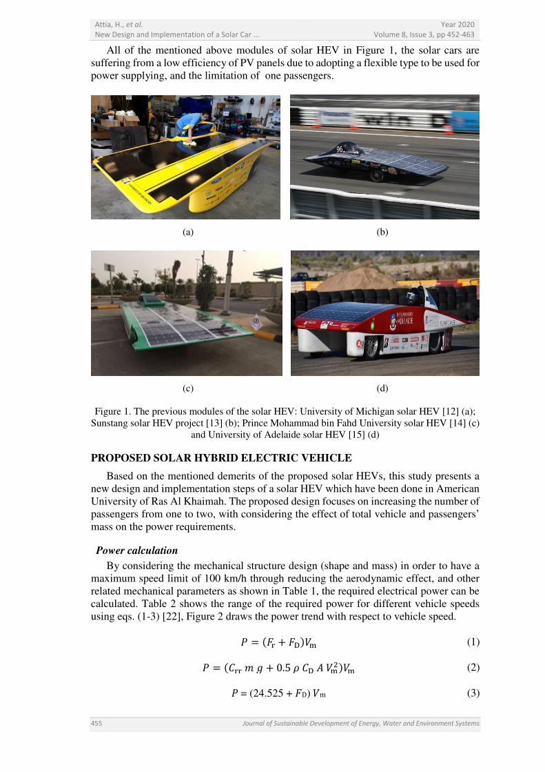
All of the mentioned above modules of solar HEV in Figure 1, the solar cars are
suffering from a low efficiency of PV panels due to adopting a flexible type to be used for
power supplying, and the limitation of one passengers.
(a)
(b)
(c)
(d)
Figure 1. The previous modules of the solar HEV: University of Michigan solar HEV [12] (a);
Sunstang solar HEV project [13] (b); Prince Mohammad bin Fahd University solar HEV [14] (c)
and University of Adelaide solar HEV [15] (d)
PROPOSED SOLAR HYBRID ELECTRIC VEHICLE
Based on the mentioned demerits of the proposed solar HEVs, this study presents a
new design and implementation steps of a solar HEV which have been done in American
University of Ras Al Khaimah. The proposed design focuses on increasing the number of
passengers from one to two, with considering the effect of total vehicle and passengers’
mass on the power requirements.
Power calculation
By considering the mechanical structure design (shape and mass) in order to have a
maximum speed limit of 100 km/h through reducing the aerodynamic effect, and other
related mechanical parameters as shown in Table 1, the required electrical power can be
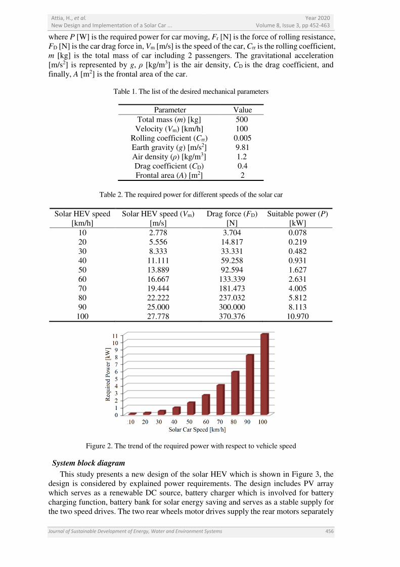
calculated. Table 2 shows the range of the required power for different vehicle speeds
using eqs. (1-3) [22], Figure 2 draws the power trend with respect to vehicle speed.
� � ��� � ��� (1)
� � ���� � � 0.5 � �� � �� (2)
� = (24.525 + �D) m (3)
Attia, H., et al.
New Design and Implementation of a Solar Car ...
Year 2020
Volume 8, Issue 3, pp 452-463
Journal of Sustainable Development of Energy, Water and Environment Systems 456
where P [W] is the required power for car moving, Fr [N] is the force of rolling resistance,
FD [N] is the car drag force in, Vm [m/s] is the speed of the car, Crr is the rolling coefficient,
m [kg] is the total mass of car including 2 passengers. The gravitational acceleration
[m/s2] is represented by g, ρ [kg/m3] is the air density, CD is the drag coefficient, and
finally, A [m2] is the frontal area of the car.
Table 1. The list of the desired mechanical parameters
Parameter Value
Total mass (m) [kg] 500
Velocity (Vm) [km/h] 100
Rolling coefficient (Crr) 0.005
Earth gravity (g) [m/s2] 9.81
Air density (ρ) [kg/m3] 1.2
Drag coefficient (CD) 0.4
Frontal area (A) [m2] 2
Table 2. The required power for different speeds of the solar car
Solar HEV speed
[km/h]
Solar HEV speed (Vm)
[m/s]
Drag force (FD)
[N]
Suitable power (P)
[kW]
10 2.778 3.704 0.078
20 5.556 14.817 0.219
30 8.333 33.331 0.482
40 11.111 59.258 0.931
50 13.889 92.594 1.627
60 16.667 133.339 2.631
70 19.444 181.473 4.005
80 22.222 237.032 5.812
90 25.000 300.000 8.113
100 27.778 370.376 10.970
Figure 2. The trend of the required power with respect to vehicle speed
System block diagram
This study presents a new design of the solar HEV which is shown in Figure 3, the
design is considered by explained power requirements. The design includes PV array
which serves as a renewable DC source, battery charger which is involved for battery
charging function, battery bank for solar energy saving and serves as a stable supply for
the two speed drives. The two rear wheels motor drives supply the rear motors separately
Attia, H., et al.
New Design and Implementation of a Solar Car ...
Year 2020
Volume 8, Issue 3, pp 452-463
457 Journal of Sustainable Development of Energy, Water and Environment Systems
for vehicle motion. The design facilitates the connecting and wiring steps of the involved
electrical devices to be able to connect in the engineering’s workshop of the school of
engineering of the university.
Figure 3. Block diagram of the proposed design of the solar HEV
Solar panel function is converting the incident solar energy into a certain quantity of
the electrical power [23]. The solar PV array involves 3 panel module SPR-E19-320W of
19% efficiency. Table 3 shows the selected PV panel specifications [24]. The dimensions
of the selected PV panels are matched with the vehicle’s dimensions.
Table 3. The specifications of the selected solar panel module SPR-E19-320W
Parameter Value
Dimensions [mm] 1,559 × 1,046 × 46
Weight [kg] 18.6
Peak power [W] 320
Efficiency [%] 19.6
Rated voltage (Vmpp) [V] 54.7
Rated current (Impp) [A] 5.86
Open circuit voltage [V] 64.8
Short circuit current [A] 6.24
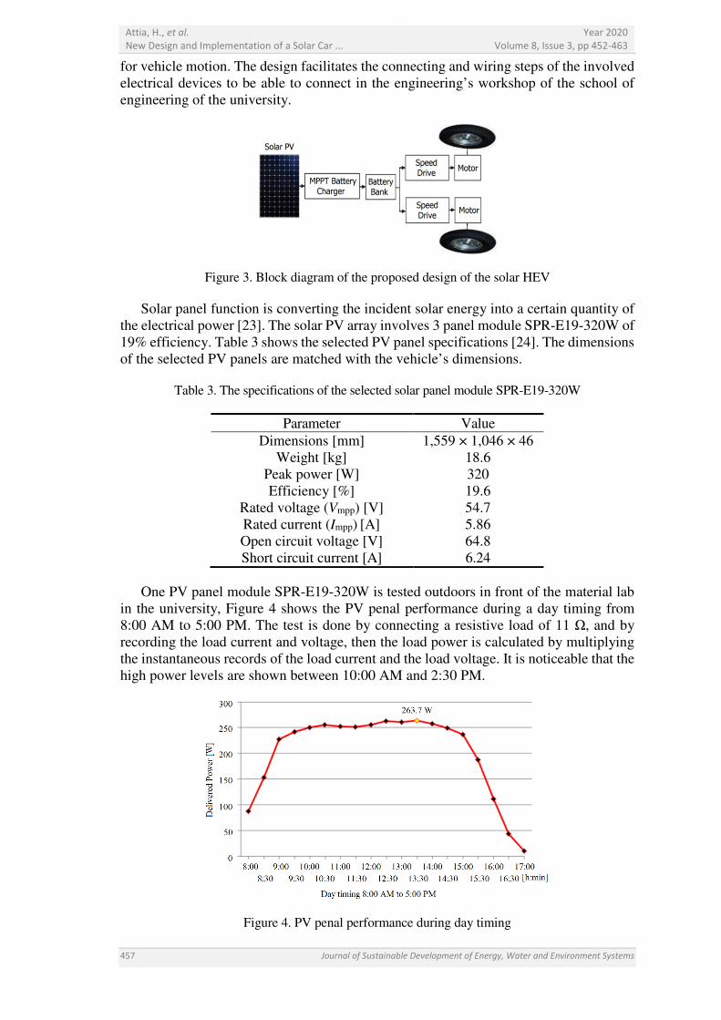
One PV panel module SPR-E19-320W is tested outdoors in front of the material lab
in the university, Figure 4 shows the PV penal performance during a day timing from
8:00 AM to 5:00 PM. The test is done by connecting a resistive load of 11 Ω, and by
recording the load current and voltage, then the load power is calculated by multiplying
the instantaneous records of the load current and the load voltage. It is noticeable that the
high power levels are shown between 10:00 AM and 2:30 PM.
Figure 4. PV penal performance during day timing
Attia, H., et al.
New Design and Implementation of a Solar Car ...
Year 2020
Volume 8, Issue 3, pp 452-463
Journal of Sustainable Development of Energy, Water and Environment Systems 458
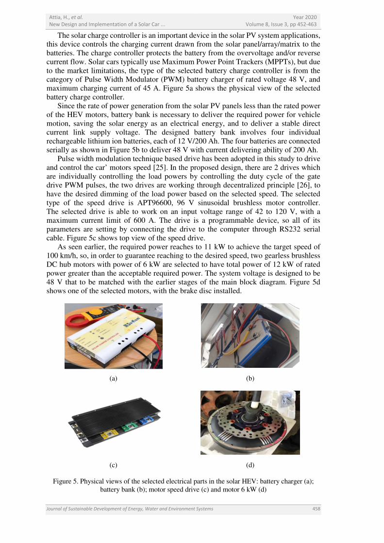
The solar charge controller is an important device in the solar PV system applications, this device controls the charging current drawn from the solar panel/array/matrix to the
batteries. The charge controller protects the battery from the overvoltage and/or reverse
current flow. Solar cars typically use Maximum Power Point Trackers (MPPTs), but due
to the market limitations, the type of the selected battery charge controller is from the category of Pulse Width Modulator (PWM) battery charger of rated voltage 48 V, and
maximum charging current of 45 A. Figure 5a shows the physical view of the selected
battery charge controller.
Since the rate of power generation from the solar PV panels less than the rated power of the HEV motors, battery bank is necessary to deliver the required power for vehicle
motion, saving the solar energy as an electrical energy, and to deliver a stable direct
current link supply voltage. The designed battery bank involves four individual
rechargeable lithium ion batteries, each of 12 V/200 Ah. The four batteries are connected serially as shown in Figure 5b to deliver 48 V with current delivering ability of 200 Ah.
Pulse width modulation technique based drive has been adopted in this study to drive
and control the car’ motors speed [25]. In the proposed design, there are 2 drives which
are individually controlling the load powers by controlling the duty cycle of the gate drive PWM pulses, the two drives are working through decentralized principle [26], to
have the desired dimming of the load power based on the selected speed. The selected
type of the speed drive is APT96600, 96 V sinusoidal brushless motor controller.
The selected drive is able to work on an input voltage range of 42 to 120 V, with a maximum current limit of 600 A. The drive is a programmable device, so all of its
parameters are setting by connecting the drive to the computer through RS232 serial
cable. Figure 5c shows top view of the speed drive.
As seen earlier, the required power reaches to 11 kW to achieve the target speed of 100 km/h, so, in order to guarantee reaching to the desired speed, two gearless brushless
DC hub motors with power of 6 kW are selected to have total power of 12 kW of rated
power greater than the acceptable required power. The system voltage is designed to be
48 V that to be matched with the earlier stages of the main block diagram. Figure 5d shows one of the selected motors, with the brake disc installed.
(a)
(b)
(c)
(d)
Figure 5. Physical views of the selected electrical parts in the solar HEV: battery charger (a);
battery bank (b); motor speed drive (c) and motor 6 kW (d)
Attia, H., et al.
New Design and Implementation of a Solar Car ...
Year 2020
Volume 8, Issue 3, pp 452-463
459 Journal of Sustainable Development of Energy, Water and Environment Systems
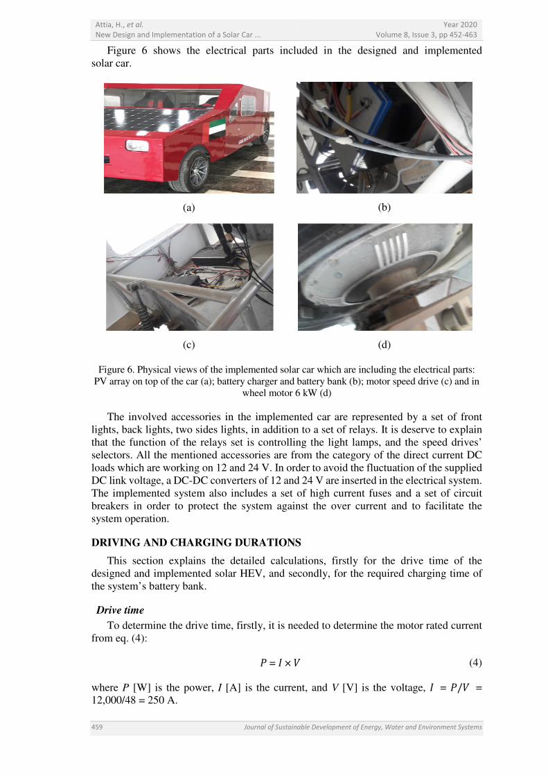
Figure 6 shows the electrical parts included in the designed and implemented
solar car.
(a)
(b)
(c)
(d)
Figure 6. Physical views of the implemented solar car which are including the electrical parts:
PV array on top of the car (a); battery charger and battery bank (b); motor speed drive (c) and in
wheel motor 6 kW (d)
The involved accessories in the implemented car are represented by a set of front
lights, back lights, two sides lights, in addition to a set of relays. It is deserve to explain
that the function of the relays set is controlling the light lamps, and the speed drives’
selectors. All the mentioned accessories are from the category of the direct current DC
loads which are working on 12 and 24 V. In order to avoid the fluctuation of the supplied
DC link voltage, a DC-DC converters of 12 and 24 V are inserted in the electrical system.
The implemented system also includes a set of high current fuses and a set of circuit
breakers in order to protect the system against the over current and to facilitate the
system operation.
DRIVING AND CHARGING DURATIONS
This section explains the detailed calculations, firstly for the drive time of the
designed and implemented solar HEV, and secondly, for the required charging time of
the system’s battery bank.
Drive time
To determine the drive time, firstly, it is needed to determine the motor rated current
from eq. (4):
� = � × (4)
where P [W] is the power, I [A] is the current, and V [V] is the voltage, � = �/ =
12,000/48 = 250 A.
Attia, H., et al.
New Design and Implementation of a Solar Car ...
Year 2020
Volume 8, Issue 3, pp 452-463
Journal of Sustainable Development of Energy, Water and Environment Systems 460
Drive time = Battery capacity/IMotor (5)
where drive time = 200 Ah/250 A = 0.8 h = 48 min.
Battery charging time
The charging time depends on the capacity of the battery bank and the level of the
provided current by the panels:
Charging time = Battery capacity/ICharge (6)
The quantity of the harvested power from the PV array = 3 × 320 W = 960 W.
Maximum ICharge which can be delivered by PV array = P/V = 960/48 = 20 A. So, the
charging time = 200 Ah/20 A = 10 hours.
From the above equations, the battery bank takes around 10 hours for full charge.
ASPECTS OF PERFOMANCE IMPROVEMENT
The presented design is characterized by the flexibility in terms of the design
modifying leading to the system’s performance enhancement. From this point of view,
this section focuses on increasing the harvested power from solar energy by replacing the
selected PV panels by other type of higher power such as SL360TU-36MD of peak
power 360 W, and study the positive effects of this replacement on the charging
time length.
The harvested quantity of rated power from solar array = 3 × 360 W = 1,080 W.
Maximum ICharge that can be delivered from solar array = P/V = 1,080/48 = 22.5 A.
So, charging time = 200 Ah/22.5 A = 8.9 hours.
It is clearly noticeable that the reduction of the charging time by around 11% of the
battery bank.
Based on the above analysis, to enhance the level of the harvested power from solar
energy, either select a higher power PV panel or increase the number of the PV panels by
fixing additional flexible type PV panels on the car sides.
In terms of increase the maximum limit of the car speed, the motor type is needed to be
reconsidered with respect to speed capability.
On the other hand, to improve the car performance, the car’s structure mass can be
reduced, either by modifying the structure shape or by selecting a lighter metal in order to
have a reduction in the power requirement.
In addition, MPPT functioning of the battery bank charge controller will increase the
level of the harvesting power and consequently will contribute positively in system
enhancement. The MPPT capability and the system losses analysis are subjected as a
future works of this study.
All the above mentioned improving aspects (in case adopted) definitely will enhance
the car performance in terms of battery bank charging time, driving time, and maximum
speed limit.
Here, it deserves to mention that for system improving, additional parameters are
needed to be considered, such as, physical dimensions, and PV panel specifications.
CONCLUSION AND FUTURE WORKS
AURAK solar car is presented in this paper as a hybrid electric vehicles powered by
solar energy. Firstly, the required electrical power with respect to the maximum limit of
vehicle’ speed is calculated, the speed calculation is considered the mechanical design of
the car structure and the allowable mass limit. Secondly, the implementation steps of the
solar HEV is done based on a new electrical system design. Solar energy is adopted as an
Attia, H., et al.
New Design and Implementation of a Solar Car ...
Year 2020
Volume 8, Issue 3, pp 452-463
461 Journal of Sustainable Development of Energy, Water and Environment Systems
important renewable energy source to charge the designed battery bank through PWM
battery charge controller. Then, the manufactured solar car is tested and driven
successfully inside AURAK University. The driving indicated the integration and the
matching among the vehicle’s parts and promising for high performance prototype.
The future work sides for performance improving can be represented by selecting more
efficient PV panel with adopting MPPT, selecting thinner wheels to reduce the friction
effects, as well as reduce the car’s structure mass. All the mentioned future sides if
considered, the system performance definitely will be improved in terms of reduction the
charging time of the battery bank, and increasing the driving time of the car.
NOMENCLATURE
A frontal area [m2]
CD drag coefficient [-]
Crr rolling coefficient [-]
FD drag force [N]
Fr rolling resistance force [N]
g earth gravity [m/s2]
I current [A]
m mass [kg]
P required power [W]
V voltage [V]
Vm maximum velocity [km/h]
Greek letters
ρ air density [kg/m3]
REFERENCES
1. Khan, M. and Kar, N. C., Hybrid Electric Vehicles for Sustainable Transportation:
A Canadian Perspective, World Electric Vehicle Journal, Vol. 3, No. 1, pp 551-562,
2009, https://doi.org/10.3390/wevj3030551
2. Nicolae, P.-M., Nicolae, I.-D. and Smărăndescu, I.-D., On Designing of the Main
Elements of a Hybrid-Electric Vehicle Driving System, Journal of Power and Energy
Engineering, Vol. 2, No. 4, pp 103-112, 2014, https://doi.org/10.4236/jpee.2014.24016
3. Simic, D. and Bauml, T., Implementation of Hybrid Electric Vehicles using the Vehicle
Interfaces and the Smart Electric Drives Libraries, Proceedings of the 6th International
Modelica Conference, pp 557-563, Bielefeld, Germany, 2008.
4. Amador, M. A. Z., Lina, M. A. C., Aquino, A. G., Gutteres, F. A., Ganggangan, A. U.
and Beltran Jr., A. A., Design and Implementation of Power Management System
Utilizing Supercapacitors for Hybrid Vehicles, International Journal of Scientific
Engineering and Technology, Vol. 3, No. 8, pp 1074-1077, 2014.
5. Panday, A. and Bansal, H. O., Energy Management Strategy Implementation for Hybrid
Electric Vehicles Using Genetic Algorithm Tuned Pontryagin’s Minimum Principle
Controller, International Journal of Vehicular Technology, Vol. 2016, p 13, Article ID
4234261, 2016, https://doi.org/10.1155/2016/4234261
6. Ahmed, A. and Cui, S., Different Architectures and Modes of Operation of HEV Based
on Permanent Magnet-Electric Variable Transmission with Rule-Based and Fuzzy
Logic Global Control Strategy, Int. J. Electric and Hybrid Vehicles, Vol. 4, No. 1,
pp 69-92, 2012, https://doi.org/10.1504/IJEHV.2012.047873
7. Attia, H. A., A Stand-alone Solar PV System with MPPT Based on Fuzzy Logic
Control for Direct Current Portable House Applications, International Review on
Attia, H., et al.
New Design and Implementation of a Solar Car ...
Year 2020
Volume 8, Issue 3, pp 452-463
Journal of Sustainable Development of Energy, Water and Environment Systems 462
Modelling and Simulations, Vol. 11, No. 6, p 377, 2018, https://doi.org/10.15866/iremos.v11i6.16074
8. Al-Waeli, A. H., Kazem, H. A. and Chaichan, M. T., Review and Design of a
Standalone PV System Performance, International Journal of Computation and
Applied Sciences, Vol. 1, No. 1, pp 1-6, 2016, https://doi.org/10.24842/1611/0001
9. Attia, H. A., Artificial Neural Networks Based Maximum Power Point Tracking
Photovoltaic System for Remote Park LED Lighting Applications,
International Review on Modelling and Simulations, Vol. 11, No. 6, 2018, https://doi.org/10.15866/iremos.v11i6.16165
10. Singh, R., Gaur, M. K. and Malvi, C. S., A Study and Design Based Simulation of
Hybrid Solar Car, International Journal of Emerging Technology and Advanced
Engineering, Vol. 3, No. 1, pp 685-691, 2013.
11. First Solar Car, http://www.automostory.com/first-solar-car.htm,
[Accessed: 18-April-2019]
12. Meet Aurum, University of Michigan Solar HEV, Ann Arbor, Michigan, USA, 2015,
http://www.solarcar.engin.umich.edu/car/, [Accessed: 18-April-2019]
13. SunStang Solar Car, http://www.sunstang.com/about-us/the-project/,
[Accessed: 18-April-2019]
14. Prince Mohammad bin Fahd University (PMU), Solar Car, Dahran,
Saudi Arabia, http://www.pmu.edu.sa/PDF-HTML/Solar%20Car/Solar_Car-6.html,
[Accessed: 18-April-2019]
15. Jonathan Hicks and Bailey Nassau, Lumen 2, http://ausrt.com/lumen2,
[Accessed: 18-April-2019]
16. Zhang, X., Chau, K. T. and Chan, C. C., Design and Implementation of a
Thermoelectric-Photovoltaic Hybrid Energy Source for Hybrid Electric Vehicles,
World Electric Vehicle Journal, Vol. 3, No. 2, pp 271-281, 2009, https://doi.org/10.3390/wevj3020271
17. Zhang, X., Chau, K. T. and Chan, C. C., A Multi-hybrid Energy System for Hybrid
Electric Vehicles, World Electric Vehicle Journal, Vol. 4, No. 1, pp 505-510, 2010, https://doi.org/10.3390/wevj4030505
18. Rajkumar, D., Gokul, C., Sabareeshwari, K. and Subathra, M., Design and
Development of Hybrid Vehicle Smart Control System with Solar Charging,
International Research Journal of Engineering and Technology, Vol. 5, No. 7,
pp 2267-2272, 2018.
19. Sankar, A. B. and Seyezhai, R., Simulation and Implementation of Solar Powered
Electric Vehicle, Circuits and Systems, Vol. 7, No. 6, pp 643-661, 2016, https://doi.org/10.4236/cs.2016.76055
20. Ashish, K. S., Lokesh, S., Arpit, G., Majid, I., Dhananjay, S. and Mukesh K. G.,
Solar Electric Powered Hybrid Vehicle, Journal of Electronic Design Technology,
Vol. 6, No. 3, 2015.
21. Spina, M. A., de la Vega, R. J., Rossi, S. R., Santillán, G., Leegstra, R. C., Verucchi, C.,
Gachen, F. A., Romero, R. E. and Acosta, G. G., Some Issues on the Design of a Solar
Vehicle Based on Hybrid Energy System, International Journal of Energy Engineering,
Vol. 2, No. 1, pp 15-21, 2012, https://doi.org/10.5923/j.ijee.20120201.03
22. McCormick, B. W., Aerodynamics, Aeronautics, and Flight Mechanics, John Wiley &
Sons Inc., New York, USA, 1979.
23. Shiva Kumar, B. and Sudhakar, K., Performance Evaluation of 10 MW Grid Connected
Solar Photovoltaic Power Plant in India, Energy Reports, Vol. 1, pp 184-192, 2015, https://doi.org/10.1016/j.egyr.2015.10.001
24. Attia, H. A. and Del Ama Gonzalo, F., Stand-alone PV System with MPPT Function
Based on Fuzzy Logic Control for Remote Building Applications, International
Journal of Power Electronics and Drive Systems, Vol. 10, No. 2,
pp 842-851, 2019, https://doi.org/10.11591/ijpeds.v10.i2.pp842-851

Attia, H., et al.
New Design and Implementation of a Solar Car ...
Year 2020
Volume 8, Issue 3, pp 452-463
463 Journal of Sustainable Development of Energy, Water and Environment Systems
25. Yaqub, M. F., Adeel, M. S. and Izhar, T., Variable Voltage Source Inverter with
Controlled Frequency Spectrum Based on Random Pulse Width Modulation,
International Journal of Power Electronics and Drive Systems, Vol. 2, No. 2, pp 25-34,
2012, https://doi.org/10.11591/ijpeds.v2i1.150
26. Wasif Umar, M., Yahaya, N. B. and Baharuddin, Z. B., PWM Dimming Control for
High Brightness LED Based Automotive Lighting Applications, International Journal
of Power Electronics and Drive Systems, Vol. 7, No. 5,
pp 2434-2440, 2017, https://doi.org/10.11591/ijece.v7i5.pp2434-2440
Paper submitted: 11.02.2019
Paper revised: 18.04.2019
Paper accepted: 18.04.2019