Network Infrastructure Standard - Vanderbilt IT The information in this document shall be used as a...
35
Network Infrastructure Standard Vanderbilt University - Information Technology Network Services
Transcript of Network Infrastructure Standard - Vanderbilt IT The information in this document shall be used as a...
Network Infrastructure Standard
Vanderbilt University - Information Technology Network Services
Vanderbilt University Page 2 of 35 v.1.0 1/23/2018 {initials}
Table of Contents
1. General Project Terms and Conditions ……………………………………. 3
2. Standards and Contractor Qualifications…………………………………... 8
3. General Specifications for ANSI/TIA 568C Wiring Standard…………….. 9
4. General Specifications for Fiber Optic Cabling…………………………...11
5. General Specifications for Coaxial Cabling……………………………….11
6. General Specifications for Unshielded Twisted Pair (cat. 3) Cabling…….12
7. Cabling Pathways………………………………………………………….13
8. Building and Communications Equipment Rooms………………………..14
9. Labeling Requirements…………………………………………………….19
10. Grounding and Bonding……………………………………………………21
11. Fire Stopping……………………………………………………………….23
Appendix A: Racks………………………..…………………………………..24
Appendix B: Building and Equipment Room Layouts………………………..28
Appendix C: Material List…………………………….………………………30
Appendix D: Acronyms……………………………..………………………...33
Appendix E: Approved Cabling Vendors……………………………………..35
Vanderbilt University Page 3 of 35 v.1.0 1/23/2018 {initials}
1 General Project Terms and Conditions
1.0 The information in this document shall be used as a guideline for the design and
installation of communications infrastructure as required by Vanderbilt
University Information Technology (VUIT) in Vanderbilt owned and/or occupied
facilities. This document does not address any other low voltage needs or
requirements. It is intended for use by Architects, Engineers and Contractors to
guide in the design and installation of a comprehensive network distribution
system, which is to include but not limited to copper and fiber distribution both
internal and external to the building.
1.1 All projects require a custom design of communications components to meet the
specific architectural requirements of the facility; representatives from VUIT will
work with the project design team to assist in the development of the
distribution design.
1.2 The contractor must provide all notices, file all plans, acquire any licenses and
permits, pay all fees and back charges, and obtain all necessary approvals from
the Authorities having Jurisdiction (AHJ) so as to perform all work required, this
is to include specifications, drawings, addendums, and change orders, in
accordance with the legal requirements.
1.3 A representative of VUIT will be assigned at the start of the project. All
communications concerning the project should be addressed to the VUIT
representative. The “official” response for any issues or concerns will be from the
VUIT appointed representative.
1.4 The communications contractor shall have a project superintendent available at
all times for the duration of the project.
1.5 The communications contractor shall comply with all National Electric Codes,
American National Standards Institute, Electronic Industry Alliance and the
Telecommunications Industry Association (ANSI/EIA/TIA) standards.
Vanderbilt University Page 4 of 35 v.1.0 1/23/2018 {initials}
General Project Terms and Conditions (Continued)
1.6 The communications contractor shall be responsible for supplying all labor and
tools required for a complete installation of the structured cabling, fiber optic
system, and CaTV (if required) systems, meeting all terms, conditions, and the
requirements of this document and local codes or ordinances.
1.7 The Contractor shall perform all work according to Federal, State, and local
codes, rules, regulations, and ordinances governing the work, and as fully part of
the specifications as if herein repeated or hereto attached. If the Contractor
should note items in the drawings or the specifications, construction of which
would be code violations, promptly call them to the attention of the owner's
representative in writing. Where the requirements of other sections of the
specifications are more stringent than applicable codes, rules, regulations, and
ordinances, the specifications shall apply.
1.8 The communications contractor must provide brand names and part numbers of
all items to complete the project. Vanderbilt University requires the
communications contractor to utilize the items listed in Appendix C. Any item not
listed in Appendix C, the contractor shall submit to VUIT brand names, item
numbers and any pertinent data sheets for approval.
1.9 The communications contractor, upon request, shall provide a per drop cost. This
will be used in the pricing of any additional drops not listed on drawings or in bid
documents.
1.10 All penetrations made by the communications contractor in floors, ceilings and
walls shall be fire-stopped according to the appropriate NEC code. All
penetrations must maintain the fire rating of the surface being penetrated.
1.11 Any penetrations must be sized to accommodate two (2) times the number of
cables being installed.
1.12 All penetrations in ceilings, walls and other parts of the building made by the
contractor must be restored to their original condition or better.
Vanderbilt University Page 5 of 35 v.1.0 1/23/2018 {initials}
General Project Terms and Conditions (Continued)
1.13 If the contractor must disturb any materials that are suspected to be toxic or
hazardous, the contractor shall cease work in that area until written notice to
proceed is received from Vanderbilt University.
1.14 When penetrating through walls or floors, the contractor is responsible for
controlling the resulting dust by shielding areas and covering furnishings to
prevent contamination. The contractor is also responsible for controlling dust
and debris caused by the removal and replacement of ceiling tiles.
1.15 The contractor shall remove all rubbish and equipment and shall leave the
premises in a neat and clean condition at the end of each workday.
1.16 All work and material movement must occur in the least disruptive manner as
possible, and at the convenience of Vanderbilt University. If access to an area
necessitates the movement of furniture or other items, it is the contractor’s
responsibility to move or coordinate the removal and return of these items to
their original location and orientation. Unless authorized by the project
coordinator, all items must be return to their original locations before ceasing
work each day.
1.17 Removing and replacing ceiling tiles is the responsibility of the contractor.
Replacement of damaged or soiled ceiling tiles is also the responsibility of the
contractor.
1.18 Contractor shall provide a twenty (20) year warranty for workmanship and
compliance as defined by Commscope/Systimax PartnerPro™ warranty as it
pertains to the structured cabling system.
1.19 Contractors must wear an I.D. badge while on site. This badge must include a
picture of the employee and the company name.
1.20 There may be other contractors working in the area, it is the responsibility of the
contractor to coordinate with other contractors in order to complete their work
within allotted time frame.
Vanderbilt University Page 6 of 35 v.1.0 1/23/2018 {initials}
General Project Terms and Conditions (Continued)
1.21 The contractor upon request shall submit, in writing, the planned work schedule
and progress reports to the VUIT representative.
1.22 The contractor may be required to attend status meeting as designated by the
VUIT representative.
1.23 In the event that a BER/CER is not completed at the time of the cabling
installation, then the contractor will neatly bundle, label (contractor’s name and
contact information) and secure all cabling so as not to interfere with the
construction of the BER/CER.
Vanderbilt University Page 7 of 35 v.1.0 1/23/2018 {initials}
General Project Terms and Conditions (Continued)
Vanderbilt University Page 8 of 35 v.1.0 1/23/2018 {initials}
1.24 All materials and equipment shall be manufactured, installed and tested as
specified in the latest editions of the following:
ANSI/TIA/EIA
1.24.2 TIA-526-7 – Optical Power Loss Measurement of Installed Single-
Mode Fiber Cable Plant
1.24.3 TIA-526-14-B – Optical Power Loss Measurement of Installed
Multimode Fiber Cable Plant
1.24.3 TIA-568-C.0 – Generic Telecommunications Cabling for Customer
Premises
1.24.4 TIA-568-C.1 – Commercial Building Telecommunications Cabling
Standard Part 1: General Requirements
1.24.5 TIA-568-C.2 – Balanced Twisted-Pair Telecommunications Cabling
and Components Standards
1.24.6 TIA-568-C.3 – Optical Fiber Cabling Components Standard
1.24.7 TIA-568-C.4 – Broadband Coaxial Cabling and Components Standard
1.24.8 TIA-569-C – Telecommunications Pathways and Spaces
1.24.9 TIA-570-C – Residential Telecommunications Infrastructure
Standard
1.24.10 TIA-598-C – Optical Fiber Cable Color Coding
1.24.11 TIA-606-B – Administration Standard for Commercial
Telecommunications Infrastructure
1.24.12 TIA-607-B – Commercial Building Grounding and Bonding
Requirements for Telecommunications
1.24.13 TIA-758-B – Customer-Owned Outside Plant Telecommunications
Infrastructure Standard
1.24.14 TIA-942-A – Telecommunications Infrastructure Standard for Data
Centers
1.24.15 TIA-942-A-1 – Telecommunications Infrastructure Standard for Data
Centers, Addendum 1-Cabling Guidelines for Data Center Fabrics
1.24.16 TIA-1179 – Healthcare Facility Telecommunications Infrastructure
Standard
Vanderbilt University Page 9 of 35 v.1.0 1/23/2018 {initials}
General Project Terms and Conditions (Continued)
1.24.17 TSB-67 – Performance Specifications for Field Testing of UTP Cable
Systems
1.24.18 AV-DRM – Audio/Visual Design Reference Manual
1.24.19 ESS-DRM – Electronic Safety and Security Design Reference Manual
1.24.20 ITS-IMM – Information Transport Systems Installation Methods
Manual
1.24.21 N-DRM – Network Design Reference Manual
1.24.22 OSP-DRM – Outside Plant Design Reference Manual
1.24.23 TDMM – Telecommunications Distribution Methods Manual
1.24.24 W-DRM – Wireless Design Reference Manual
FCC
1.24.25 Title 47 CFR Part 15 – Electromagnetic Radiation
1.25.26 Title 47 CFR Part 68 – Direct Connection of Telecommunications
Equipment and Customer Premises Wiring
IEEE – Institute of Electrical and Electronics Engineers, Inc.
1.25.27 NEC – National Electric Code
1.25.28 NFPA 70 – National Fire Protection Association
NESC – National Electrical Safety Code
OSHA – Occupational Safety and Health Act
2.0 Standards and Contractor Qualifications
2.1 Vanderbilt University’s structured cabling standard is the ANSI/TIA 568-C. The University has chosen the CommScope Systimax solution to the ANSI/TIA 568-C standard. The communications contractor must be certified and be in good standing as a CommScope PartnerPRO™.
2.2 Vanderbilt University’s fiber cabling standard is the ANSI/TIA 568-C. The University has chosen the CommScope Systimax solution to the ANSI/TIA 568-C standard. The communications contractor must be certified and be in good standing as a CommScope PartnerPRO™.

Vanderbilt University Page 10 of 35 v.1.0 1/23/2018 {initials}
Standards and Contractor Qualifications (Continued)
2.3 The communications contractor shall have the following: 2.3.1 Comprehensive knowledge and understanding of the latest revision of the Building Industry Consulting Services International’s (BICSI), Telecommunications Distribution Methods Manual (TDMM). 2.3.2 At least two (1) Registered Communications Distribution Designers (RCDD) on staff and must be available to resolve any field installation issues. 2.3.3 Installation crews should be familiar with the BICSI ITS Cabling Installation Program
2.4 The communications contractor shall have at least five (5) years of experience installing and servicing telecommunications systems. The contractor shall provide, upon request, a list of projects that are similar in scope and magnitude, this list is to include references and contact information.
2.5 The accuracy and completeness of the services provided by the
communications contractor, all analytical laboratory testing, and all sub-contractors may be subject to quality assurance audits by Vanderbilt University.
2.6 The communications contractor must be on the approved vendor list as
determined by Commscope Enterprise Solutions and Vanderbilt University Information Technology (VUIT). See Appendix E.
3.0 General Specifications for the ANSI/TIA Structured Cabling System
3.1 All horizontal UTP cabling to be installed for a typical telecommunication outlet shall meet or exceed ANSI/TIA Category 6 specifications and be yellow in color. See Appendix C for part numbers. In certain situations different cables will be needed, refer to the drawings to determine number and types of cables.
3.2 All horizontal UTP cabling to be installed for a wireless access point outlet
shall meet or exceed ANSI/TIA Category 6A specifications and be green in color. See Appendix C for part numbers.
Vanderbilt University Page 11 of 35 v.1.0 1/23/2018 {initials}
General Specifications for the ANSI/TIA Structured Cabling System (Cont.)
3.3 All horizontal cabling from BER/CER’s to outlet locations will be concealed in ceilings, walls or surface raceway. No exposed cabling will be allowed unless otherwise authorized by the VUIT network infrastructure representative.
3.4 Any cables in ceilings are to be installed in existing cable trays. Any cable not installed in cable trays shall be supported by appropriate supporting hardware. The supporting hardware shall be attached to the building structure (concrete, cement blocks or steel beam), at no time are ceiling supports, electrical conduits or hangers used to support hardware within the ceiling are to be used.
3.5 All horizontal cable runs shall be loosely wrapped using Velcro™ type straps between cable supports. Plastic cable ties are not permitted.
3.6 No cabling is to be laid on ceiling tiles, lights etc. All cable runs must maintain a minimum distance of eighteen (18) inches from fluorescent lights, motors or other sources of EMI radiation and fire suppression systems.
3.7 All metal stud penetrations are to be a minimum of one (1) inch in diameter with a non-conductive grommet installed to protect the cable from damage.
3.8 All cabling runs are to be continuous without transition points or splices. 3.9 At a minimum, all outlets must have one (1) cable installed and terminated. 3.10 No more than four (4) cables shall be installed in a single gang outlet box. 3.11 No more than eight (8) cables shall be installed in a double gang outlet box. 3.12 Communications cabling shall not be co-located within the same outlet box
as electrical circuits and must not share the same faceplate. 3.13 A minimum of twelve (12) inches of cable slack shall be available at the
outlet location. This slack is not to be stored within the outlet box. 3.14 A minimum of ten (10) feet of cable slack shall be available in the
CER/BER’s. This slack will be attached to the wall directly behind the racks as shown in Appendix B.
Vanderbilt University Page 12 of 35 v.1.0 1/23/2018 {initials}
4.0 General Specifications for Fiber Cabling
4.1 The installer shall provide a minimum of 12 strand single-mode fiber optic
cable. This count may vary depending on circumstances, VUIT in
conjunction with the low voltage designer will determine actual strand
count. All fiber optic cable shall be installed, terminated and tested in
accordance with the manufacturer’s recommendations.
4.2 All fiber optic cables are to be installed in orange inner-duct, labeled every
ten (10) feet and supported every five (5) feet per the ANSI/EIA 568C
standard. At no time is a fiber optic cable to be installed exposed.
4.3 All fiber optic cabling shall be installed as a continuous run between points
– splices are not acceptable, if a transition is necessary then approval by
the VUIT representative is required.
4.4 Multiple connectors may be used, consult the VUIT representative for
direction. All fiber strands shall be terminated with UPC/LC connectors,
with the exception of a fiber strand needed for CaTV utilization, if
applicable, then this connector shall be an APC/LC connector.
4.7 If applicable, the last strand in the entrance fiber cabling will be
terminated with an APC/LC connector to accommodate CaTV systems. The
strand to be used shall be specified in the telecommunications
design/construction documents.
5.0 General Specifications for Coaxial Cabling
5.1 Coaxial cabling between the CER and the BERs shall be 75 Ohm, NEC riser rated, and flame resistant RG-11 cable. This cable shall be homerun from the originating location (CER) to the terminating location (BER).
5.2 Coaxial cabling between the CER/BERs and outlet faceplate shall be 75 Ohm, NEC riser rated, and flame resistant RG-6 cable. This cable shall be homerun from the originating location (CER/BER) to the terminating location (communications outlet).
Vanderbilt University Page 13 of 35 v.1.0 1/23/2018 {initials}
General Specifications for Coaxial Cabling (Continued)
5.3 The RG-11 and RG-6 cables shall be terminating utilizing a snap and seal
type connector
5.4 CaTV terminating hardware will be provided by VUIT and be installed before the termination of coaxial cables can be done.
5.5 The CaTV distribution design will be provided by VUIT prior to the installation of coaxial cabling.
6.0 General Specifications for Voice Related Unshielded Twisted Pair Cabling
6.1 Installer shall provide only new ARMM riser cable for installation.
6.2 All patch panels and 110 termination blocks shall be installed, terminated
and tested in accordance with the manufacturer’s recommendations and as set forth in the standards listed in section 1.25 of this document.
6.3 A riser rated 25 UTP cable shall be installed from the terminating location in the BER to each rack located in the CERs.
6.4 Provide and install the necessary number of patch panels and/or 110
termination blocks to terminate all installed voice riser cables.
6.5 Patch panels are to be installed within equipment racks as noted in the
rack elevations found in Appendix A.
6.6 When using patch panels, the 24th port in each panel will support a 2-pair
termination scheme so that all pairs are terminated.
6.7 The design of the CER will dictate whether the use of patch panels, 110
termination blocks or both is required – coordinate specifics with the VUIT
representative.
Vanderbilt University Page 14 of 35 v.1.0 1/23/2018 {initials}
7.0 CABLING PATHWAYS
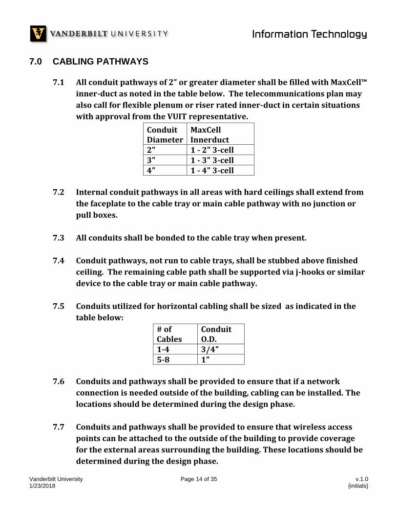
7.1 All conduit pathways of 2” or greater diameter shall be filled with MaxCell™
inner-duct as noted in the table below. The telecommunications plan may
also call for flexible plenum or riser rated inner-duct in certain situations
with approval from the VUIT representative.
Conduit Diameter
MaxCell Innerduct
2" 1 - 2" 3-cell 3" 1 - 3" 3-cell 4" 1 - 4" 3-cell
7.2 Internal conduit pathways in all areas with hard ceilings shall extend from
the faceplate to the cable tray or main cable pathway with no junction or
pull boxes.
7.3 All conduits shall be bonded to the cable tray when present.
7.4 Conduit pathways, not run to cable trays, shall be stubbed above finished
ceiling. The remaining cable path shall be supported via j-hooks or similar
device to the cable tray or main cable pathway.
7.5 Conduits utilized for horizontal cabling shall be sized as indicated in the
table below:
# of Cables
Conduit O.D.
1-4 3/4" 5-8 1"
7.6 Conduits and pathways shall be provided to ensure that if a network
connection is needed outside of the building, cabling can be installed. The
locations should be determined during the design phase.
7.7 Conduits and pathways shall be provided to ensure that wireless access
points can be attached to the outside of the building to provide coverage
for the external areas surrounding the building. These locations should be
determined during the design phase.
Vanderbilt University Page 15 of 35 v.1.0 1/23/2018 {initials}
CABLING PATHWAYS (Continued)
7.8 Pathways through “hard ceilings” will be continuous without junction or
pull boxes unless ceiling access is provided to allow unimpeded access.
7.9 Pathways through “hard ceilings” shall be sized to provide two (2) times
the capacity of the initial installation.
7.10 Outside Plant (OSP) conduit pathways shall consist of the appropriately
sized UL listed, NEMA TC6 schedule 40 or 80 rigid PVC and encased in
concrete. The duct bank shall be installed with a minimum of 24” depth of
cover.
7.11 All OSP fittings shall be UL listed, NEMA TC9 and matched to the conduit
material.
7.12 All OSP sweeps shall be factory manufactured and have a minimum 15-foot
radius.
7.13 All OSP end caps shall be factory manufactured and watertight.
(Tape is not acceptable).
7.14 All OSP duct bank spacers must be used when appropriate and shall be
high density, interlocking spacers.
7.15 Six-inch-wide metallic warning tape, orange in color, shall be placed 12”
above all underground conduit paths and marked every 24”.
7.16 All conduits shall include a polypropylene pull rope with a minimum
tensile strength of 200 pounds.
8.0 Building and Communications Equipment Rooms (BER/CER)
SPACE REQUIREMENTS 8.1.1 Building Entrance Rooms (BER) and Communications Equipment Rooms
(CER) shall be appropriately sized and rectangular in shape.
Vanderbilt University Page 16 of 35 v.1.0 1/23/2018 {initials}
(BER/CER) Equipment Rooms (Continued)
8.1.2 Variances to BER and CER sizing are acceptable but must be approved by
the VUIT representative.
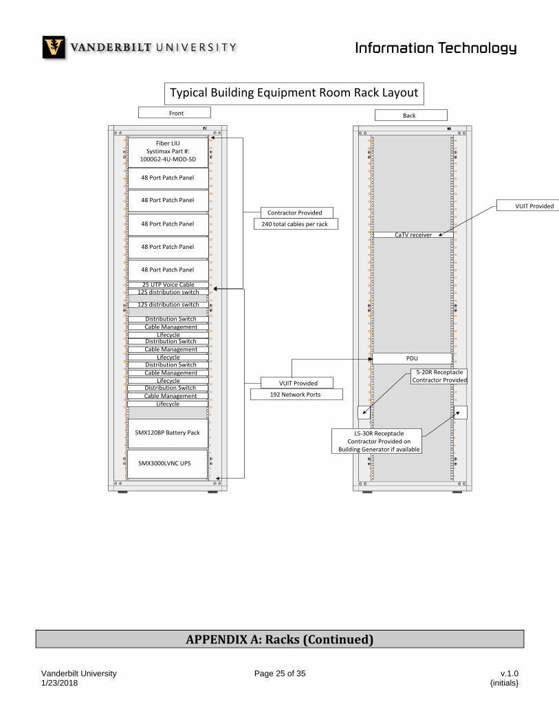
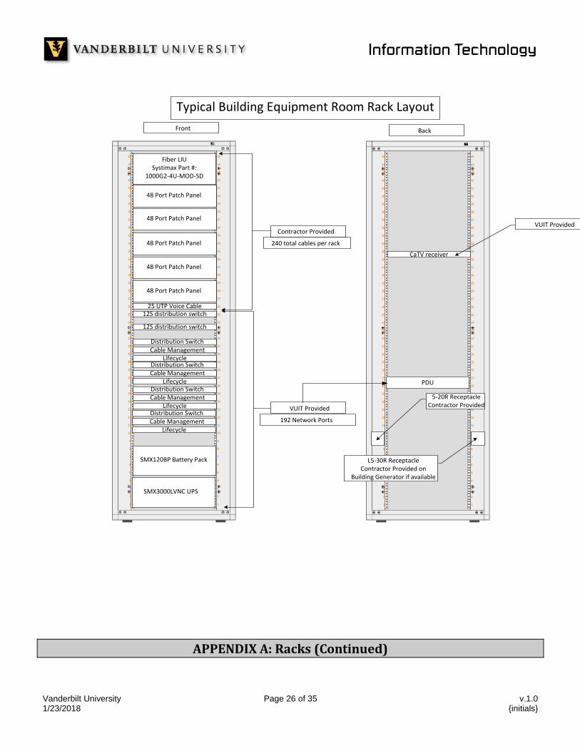
8.1.3 The sizing of BERs/CERs are contingent on the number of network drops installed. VUIT has determined that for every 240 drops, one (1) network rack must be installed. See Appendixes A and B for typical BER/CER and rack layout.
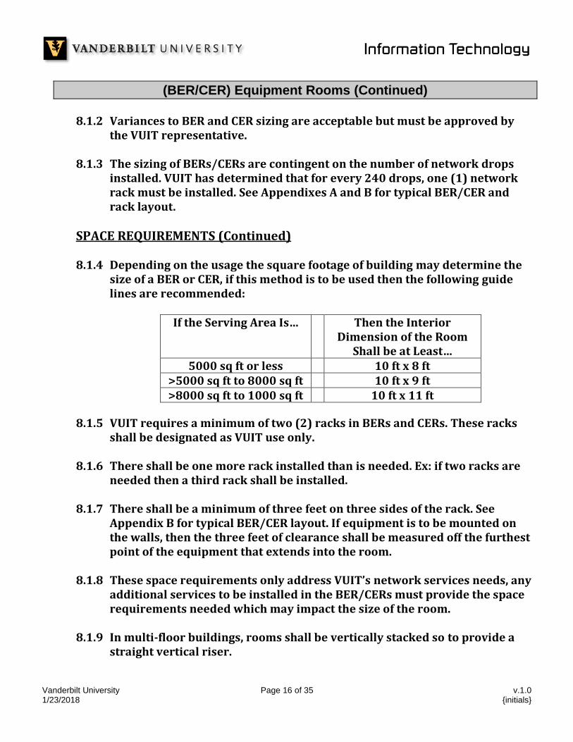
SPACE REQUIREMENTS (Continued) 8.1.4 Depending on the usage the square footage of building may determine the
size of a BER or CER, if this method is to be used then the following guide lines are recommended:
If the Serving Area Is…
Then the Interior Dimension of the Room
Shall be at Least… 5000 sq ft or less 10 ft x 8 ft
>5000 sq ft to 8000 sq ft 10 ft x 9 ft >8000 sq ft to 1000 sq ft 10 ft x 11 ft
8.1.5 VUIT requires a minimum of two (2) racks in BERs and CERs. These racks shall be designated as VUIT use only.
8.1.6 There shall be one more rack installed than is needed. Ex: if two racks are needed then a third rack shall be installed.
8.1.7 There shall be a minimum of three feet on three sides of the rack. See
Appendix B for typical BER/CER layout. If equipment is to be mounted on the walls, then the three feet of clearance shall be measured off the furthest point of the equipment that extends into the room.
8.1.8 These space requirements only address VUIT’s network services needs, any additional services to be installed in the BER/CERs must provide the space requirements needed which may impact the size of the room.
8.1.9 In multi-floor buildings, rooms shall be vertically stacked so to provide a straight vertical riser.
Vanderbilt University Page 17 of 35 v.1.0 1/23/2018 {initials}
(BER/CER) Equipment Rooms (Continued)
8.1.10 Depending on the usage of the building it may be possible to place
CER/BER rooms on alternating floors, however cabling distances must be within EIA/TIA specifications. This design must be approved by the VUIT representative.
POWER REQUIREMENTS 8.2.1 Each rack shall have one (1) NEMA 5-20R and one (1) NEMA L5-30R
receptacle attached to the rear of the rack. These outlets are to be mounted approximately 18” AFF.
8.2.3 All electrical outlets mounted on the racks shall be conduit at no time is a flexible portable power cord (SO) is to be used.
8.2.4 The electrical outlets shall not impede the rack mounting screw locations.
8.2.5 Convenience outlets shall be NEMA 5-20R installed on walls per applicable codes.
8.2.6 In some instances, certain BERs will require two (2) NEMA L6-30R
receptacles attached to the rear of the racks. These outlets are to be mounted approximately 18” AFF. This will be determined prior to construction by VUIT network infrastructure representative.
ENVIROMENTAL REQUIREMENTS 8.3.1 All BERs and CERs shall include a HVAC system capable of maintaining a
temperature within the range of 64 to 75 degrees Fahrenheit at 30 to 55 percent relative humidity.
8.3.2 System control shall be within and dedicated to the individual BER/CER.
8.3.3 Rooms must be kept clean and dust free at all times.
8.3.4 The amount of potential equipment will determine the BTU dissipation for
each BER/CER.
Vanderbilt University Page 18 of 35 v.1.0 1/23/2018 {initials}
(BER/CER) Equipment Rooms (Continued)
MISCELLANIOUS REQUIREMENTS
8.4.2 Rooms shall be located centrally within the facility to accommodate as
large an area as possible., while maintaining a 285 feet maximum
horizontal cable length between faceplate and patch panel.
8.4.3 All communications rooms must be accessible 24 hours a day, 365 days a
year.
8.4.4 All communications rooms must have corridor access. At no time should
the access be through another room.
8.4.3 BERs shall be located in close proximity to where inter-building
communications cables enter the facility.
8.4.4 Floors shall be sealed and have anti-static properties as per IEC 61000-4-2.
Carpet is NOT permitted.
8.4.5 All walls shall be covered with ¾” Fire Retardant-treated wood (FRTW)
mounted 6” AFF and be painted white. All applicable inspection quality
stamps must remain unpainted.
8.4.6 The ceiling height in BERs and CERs shall not be less than 8ft. 6in. AFF.
False ceilings are NOT permitted.
8.4.7 Router rooms shall have double doors each measuring 80”H x 36”W and
constructed without a doorsill or center post, these doors need to swing
out and lay flat.
8.4.8 BER/CERs shall have a single door measuring 80”H x 36”W, this door needs
to swing out and lay flat.
Vanderbilt University Page 19 of 35 v.1.0 1/23/2018 {initials}
(BER/CER) Equipment Rooms (Continued)
MISCELLANIOUS REQUIREMENTS (Continued)
8.4.9 Sufficient lighting shall be provided to ensure a minimum of 50 foot
candles, measured 3’ above the finished floor after all racks, cable trays
and cables are in place.
8.4.10 Rooms shall be secured via the electronic building access control system.
If no system is present, then all doors shall have the capability of adding
card readers and electronic door strikes and be identically keyed utilizing
Vanderbilt key number 1872.
8.4.11 BER and CERs shall have a clean agent fire extinguisher located within the
space below the light switch – See NFPA 75 for guidance.
8.4.12 Water or drain piping not associated with telecommunications equipment
shall NOT be present or installed directly above the BER/CERs.
8.4.13 BERs or CERs that contain supporting water or drain piping that is
associated with telecommunications equipment must also be equipped
with a leak detection system
8.4.14 Condensate or steam piping shall NOT be present in the BERs or CERs.
8.4.15 The BER shall have minimum two 4” conduits constructed for Carriers/ISPs that extend from the BER to the nearest pole/maintenance hole/pedestal at the public right of way
8.4.16 All racks are to be bolted to the floor per manufacturer’s specifications.
Vanderbilt University Page 20 of 35 v.1.0 1/23/2018 {initials}
9.0 LABELING REQUIREMENTS
9.1 Installer shall label all installed cabling.
9.2 Labeling shall not take place until all faceplates, patch panels, wiring
blocks and termination hardware are secure in their final location and
testing has been completed.
9.3 All labels shall be machine printed; handwritten labels are not acceptable.
9.4 Patch panels located within the BER/CER shall be sequentially labeled.
9.5 Outlets within rooms shall be sequentially labeled, left to right.
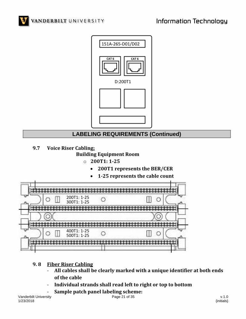
9.6 Sample faceplate-labeling scheme:
o 151A-265-D01/D02:
151A represents the building code
265 represents the room number the jack is located in
D01 represents the jack number in the room
D02 represents the jack number in the room
D:200T1 represents the terminating BER/CER
Vanderbilt University Page 21 of 35 v.1.0 1/23/2018 {initials}
151A-265-D01/D02
D:200T1 D03/D04
CAT 6 CAT 6
151A-265-D01/D02
D:200T1
LABELING REQUIREMENTS (Continued)
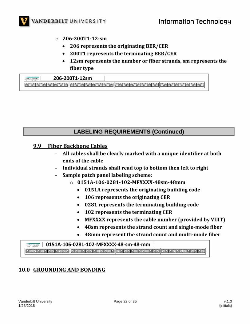
9.7 Voice Riser Cabling:
Building Equipment Room
o 200T1: 1-25
200T1 represents the BER/CER
1-25 represents the cable count
200T1: 1-25300T1: 1-25
400T1: 1-25500T1: 1-25
9. 8 Fiber Riser Cabling - All cables shall be clearly marked with a unique identifier at both ends
of the cable
- Individual strands shall read left to right or top to bottom
- Sample patch panel labeling scheme:
Vanderbilt University Page 22 of 35 v.1.0 1/23/2018 {initials}
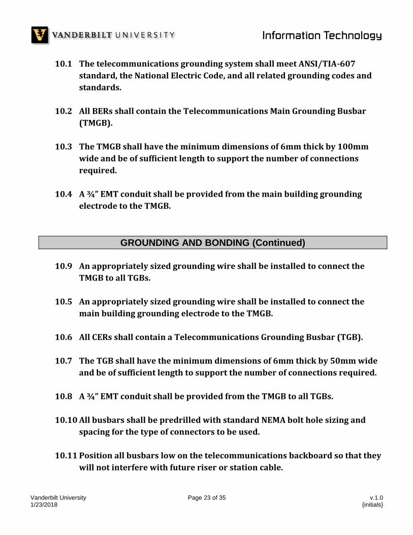
o 206-200T1-12-sm
206 represents the originating BER/CER
200T1 represents the terminating BER/CER
12sm represents the number or fiber strands, sm represents the
fiber type
206-200T1-12sm
LABELING REQUIREMENTS (Continued)
9.9 Fiber Backbone Cables
- All cables shall be clearly marked with a unique identifier at both
ends of the cable
- Individual strands shall read top to bottom then left to right
- Sample patch panel labeling scheme:
o 0151A-106-0281-102-MFXXXX-48sm-48mm
0151A represents the originating building code
106 represents the originating CER
0281 represents the terminating building code
102 represents the terminating CER
MFXXXX represents the cable number (provided by VUIT)
48sm represents the strand count and single-mode fiber
48mm represent the strand count and multi-mode fiber
0151A-106-0281-102-MFXXXX-48-sm-48-mm
10.0 GROUNDING AND BONDING
Vanderbilt University Page 23 of 35 v.1.0 1/23/2018 {initials}
10.1 The telecommunications grounding system shall meet ANSI/TIA-607
standard, the National Electric Code, and all related grounding codes and
standards.
10.2 All BERs shall contain the Telecommunications Main Grounding Busbar
(TMGB).
10.3 The TMGB shall have the minimum dimensions of 6mm thick by 100mm
wide and be of sufficient length to support the number of connections
required.
10.4 A ¾” EMT conduit shall be provided from the main building grounding
electrode to the TMGB.
GROUNDING AND BONDING (Continued)
10.9 An appropriately sized grounding wire shall be installed to connect the
TMGB to all TGBs.
10.5 An appropriately sized grounding wire shall be installed to connect the
main building grounding electrode to the TMGB.
10.6 All CERs shall contain a Telecommunications Grounding Busbar (TGB).
10.7 The TGB shall have the minimum dimensions of 6mm thick by 50mm wide
and be of sufficient length to support the number of connections required.
10.8 A ¾” EMT conduit shall be provided from the TMGB to all TGBs.
10.10 All busbars shall be predrilled with standard NEMA bolt hole sizing and
spacing for the type of connectors to be used.
10.11 Position all busbars low on the telecommunications backboard so that they
will not interfere with future riser or station cable.
Vanderbilt University Page 24 of 35 v.1.0 1/23/2018 {initials}
10.12 Route all ground wires near the edges of the telecommunications
backboard to leave the backboard unobstructed.
11.0 FIRE STOPPING
11.1 Installer shall seal all communications penetrations in accordance with the
National Fire Protection Association (NFPA), the National Electric Code
(NEC) and EIA/TIA 569 standards.
11.2 Abesco CT120 Cable Transits are the preferred method for cable sleeve
penetrations through fire rated barriers.
11.3 Fire rated pillows/putty shall be used to seal all cable tray and conduit
penetrations through fire rated barriers.
11.4 Use of acoustic putty, concrete or any other non-pliable fire/smoke barrier
is prohibited.
APPENDIX A: Racks (Continued)
Vanderbilt University Page 25 of 35 v.1.0 1/23/2018 {initials}
1 1
2 2
3 3
4 4
5 5
6 6
7 7
8 8
9 9
10 10
11 11
12 12
13 13
14 14
15 15
16 16
17 17
18 18
19 19
20 20
21 21
22 22
23 23
24 24
25 25
26 26
27 27
28 28
29 29
30 30
31 31
32 32
33 33
34 34
35 35
36 36
37 37
38 38
39 39
40 40
41 41
42 42
43 43
44 44
45 45
SMX120BP Battery Pack
SMX3000LVNC UPS
Fiber LIU Systimax Part #:
1000G2-4U-MOD-SD
Front
48 Port Patch Panel
48 Port Patch Panel
48 Port Patch Panel
48 Port Patch Panel
48 Port Patch Panel
25 UTP Voice Cable
Cable ManagementDistribution Switch
Lifecycle
Cable ManagementDistribution Switch
Lifecycle
Cable ManagementDistribution Switch
Lifecycle
Cable ManagementDistribution Switch
Lifecycle
12S distribution switch
12S distribution switch
Typical Building Equipment Room Rack Layout
Contractor Provided
VUIT Provided
Back
1 1
2 2
3 3
4 4
5 5
6 6
7 7
8 8
9 9
10 10
11 11
12 12
13 13
14 14
15 15
16 16
17 17
18 18
19 19
20 20
21 21
22 22
23 23
24 24
25 25
26 26
27 27
28 28
29 29
30 30
31 31
32 32
33 33
34 34
35 35
36 36
37 37
38 38
39 39
40 40
41 41
42 42
43 43
44 44
45 45
CaTV receiver
5-20R ReceptacleContractor Provided
VUIT Provided
PDU
192 Network Ports
240 total cables per rack
L5-30R ReceptacleContractor Provided on
Building Generator if available
APPENDIX A: Racks (Continued)
Vanderbilt University Page 26 of 35 v.1.0 1/23/2018 {initials}
1 1
2 2
3 3
4 4
5 5
6 6
7 7
8 8
9 9
10 10
11 11
12 12
13 13
14 14
15 15
16 16
17 17
18 18
19 19
20 20
21 21
22 22
23 23
24 24
25 25
26 26
27 27
28 28
29 29
30 30
31 31
32 32
33 33
34 34
35 35
36 36
37 37
38 38
39 39
40 40
41 41
42 42
43 43
44 44
45 45
SMX120BP Battery Pack
SMX3000LVNC UPS
Fiber LIU Systimax Part #:
1000G2-4U-MOD-SD
Front
48 Port Patch Panel
48 Port Patch Panel
48 Port Patch Panel
48 Port Patch Panel
48 Port Patch Panel
25 UTP Voice Cable
Cable ManagementDistribution Switch
Lifecycle
Cable ManagementDistribution Switch
Lifecycle
Cable ManagementDistribution Switch
Lifecycle
Cable ManagementDistribution Switch
Lifecycle
12S distribution switch
12S distribution switch
Typical Building Equipment Room Rack Layout
Contractor Provided
VUIT Provided
Back
1 1
2 2
3 3
4 4
5 5
6 6
7 7
8 8
9 9
10 10
11 11
12 12
13 13
14 14
15 15
16 16
17 17
18 18
19 19
20 20
21 21
22 22
23 23
24 24
25 25
26 26
27 27
28 28
29 29
30 30
31 31
32 32
33 33
34 34
35 35
36 36
37 37
38 38
39 39
40 40
41 41
42 42
43 43
44 44
45 45
CaTV receiver
5-20R ReceptacleContractor Provided
VUIT Provided
PDU
192 Network Ports
240 total cables per rack
L5-30R ReceptacleContractor Provided on
Building Generator if available
APPENDIX A: Racks (Continued)
Vanderbilt University Page 27 of 35 v.1.0 1/23/2018 {initials}
1 1
2 2
3 3
4 4
5 5
6 6
7 7
8 8
9 9
10 10
11 11
12 12
13 13
14 14
15 15
16 16
17 17
18 18
19 19
20 20
21 21
22 22
23 23
24 24
25 25
26 26
27 27
28 28
29 29
30 30
31 31
32 32
33 33
34 34
35 35
36 36
37 37
38 38
39 39
40 40
41 41
42 42
43 43
44 44
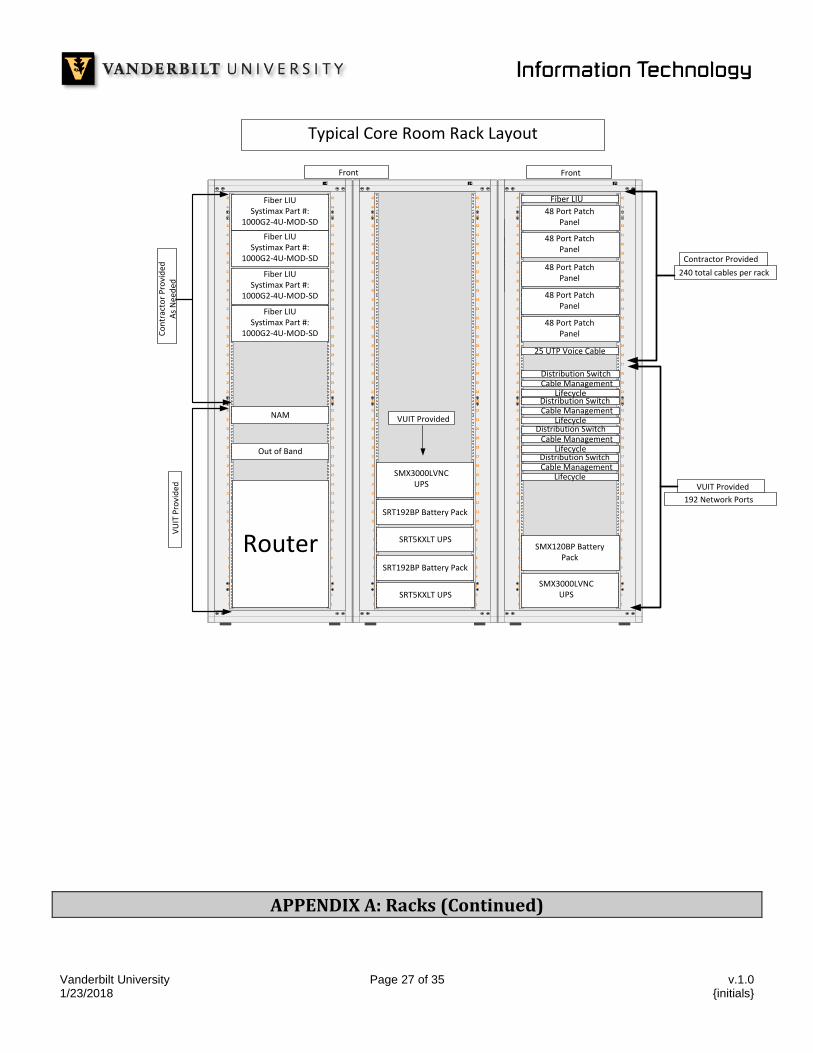
45 45Fiber LIU Systimax Part #:
1000G2-4U-MOD-SD
Router
NAM
Out of Band
Fiber LIU Systimax Part #:
1000G2-4U-MOD-SD
Fiber LIU Systimax Part #:
1000G2-4U-MOD-SD
Fiber LIU Systimax Part #:
1000G2-4U-MOD-SDCo
ntr
acto
r P
rovi
ded
As
Nee
ded
VU
IT P
rovi
ded
Typical Core Room Rack Layout
Front
192 Network Ports
240 total cables per rack
Contractor Provided
VUIT Provided
1 1
2 2
3 3
4 4
5 5
6 6
7 7
8 8
9 9
10 10
11 11
12 12
13 13
14 14
15 15
16 16
17 17
18 18
19 19
20 20
21 21
22 22
23 23
24 24
25 25
26 26
27 27
28 28
29 29
30 30
31 31
32 32
33 33
34 34
35 35
36 36
37 37
38 38
39 39
40 40
41 41
42 42
43 43
44 44
45 45
SRT5KXLT UPS
SRT192BP Battery Pack
SRT5KXLT UPS
SRT192BP Battery Pack
SMX3000LVNC UPS
Co
ntracto
r P
rovid
edV
UIT P
rovid
ed
1 1
2 2
3 3
4 4
5 5
6 6
7 7
8 8
9 9
10 10
11 11
12 12
13 13
14 14
15 15
16 16
17 17
18 18
19 19
20 20
21 21
22 22
23 23
24 24
25 25
26 26
27 27
28 28
29 29
30 30
31 31
32 32
33 33
34 34
35 35
36 36
37 37
38 38
39 39
40 40
41 41
42 42
43 43
44 44
45 45Fiber LIU
48 Port Patch Panel
48 Port Patch Panel
48 Port Patch Panel
48 Port Patch Panel
48 Port Patch Panel
Cable ManagementDistribution Switch
Lifecycle
Cable ManagementDistribution Switch
Lifecycle
Cable ManagementDistribution Switch
Lifecycle
Cable ManagementDistribution Switch
Lifecycle
SMX120BP Battery Pack
SMX3000LVNC UPS
Front
25 UTP Voice Cable
VUIT Provided
APPENDIX A: Racks (Continued)
Vanderbilt University Page 28 of 35 v.1.0 1/23/2018 {initials}
1 1
2 2
3 3
4 4
5 5
6 6
7 7
8 8
9 9
10 10
11 11
12 12
13 13
14 14
15 15
16 16
17 17
18 18
19 19
20 20
21 21
22 22
23 23
24 24
25 25
26 26
27 27
28 28
29 29
30 30
31 31
32 32
33 33
34 34
35 35
36 36
37 37
38 38
39 39
40 40
41 41
42 42
43 43
44 44
45 45
1 1
2 2
3 3
4 4
5 5
6 6
7 7
8 8
9 9
10 10
11 11
12 12
13 13
14 14
15 15
16 16
17 17
18 18
19 19
20 20
21 21
22 22
23 23
24 24
25 25
26 26
27 27
28 28
29 29
30 30
31 31
32 32
33 33
34 34
35 35
36 36
37 37
38 38
39 39
40 40
41 41
42 42
43 43
44 44
45 45
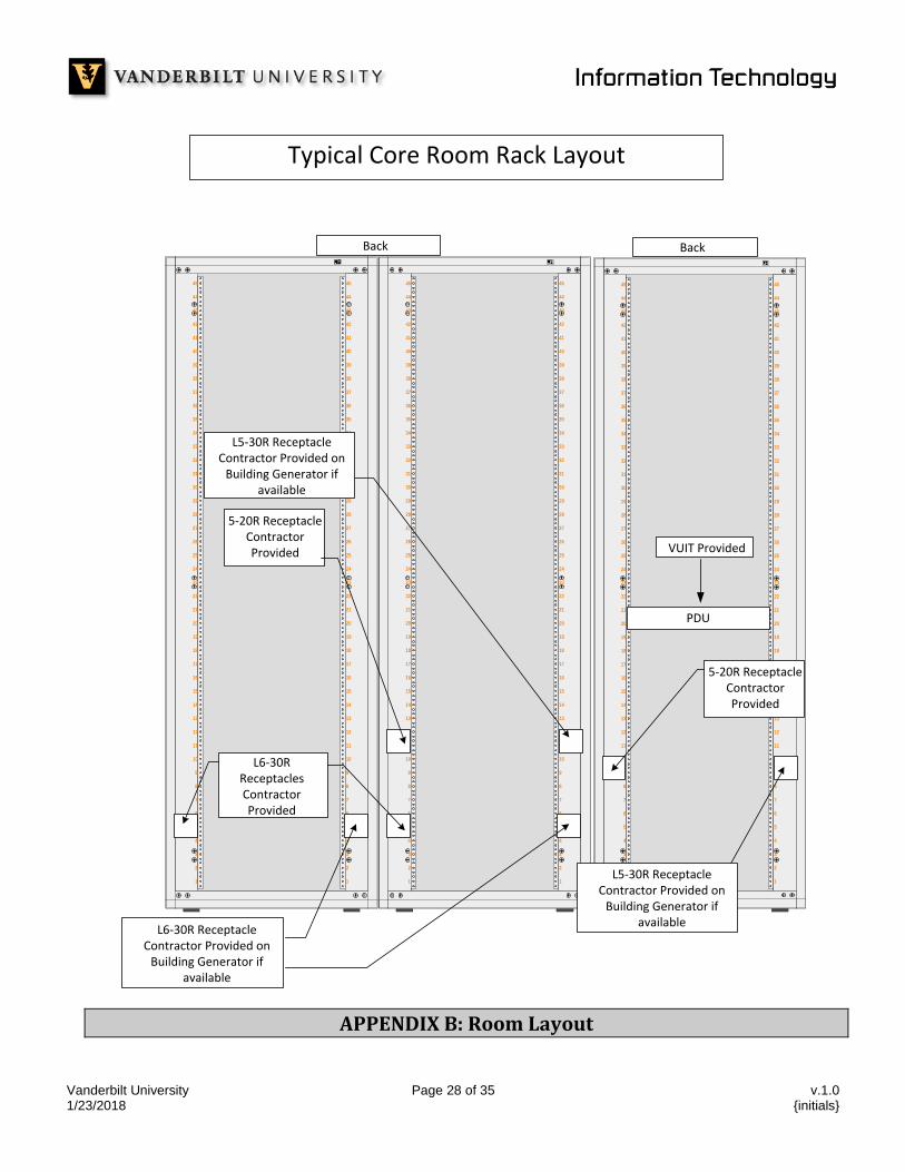
L6-30R ReceptaclesContractor Provided
5-20R ReceptacleContractor Provided
Back
L5-30R ReceptacleContractor Provided on
Building Generator if available
Back
1 1
2 2
3 3
4 4
5 5
6 6
7 7
8 8
9 9
10 10
11 11
12 12
13 13
14 14
15 15
16 16
17 17
18 18
19 19
20 20
21 21
22 22
23 23
24 24
25 25
26 26
27 27
28 28
29 29
30 30
31 31
32 32
33 33
34 34
35 35
36 36
37 37
38 38
39 39
40 40
41 41
42 42
43 43
44 44
45 45
5-20R ReceptacleContractor Provided
PDU
L5-30R ReceptacleContractor Provided on
Building Generator if available
L6-30R ReceptacleContractor Provided on
Building Generator if available
VUIT Provided
Typical Core Room Rack Layout
APPENDIX B: Room Layout

Vanderbilt University Page 29 of 35 v.1.0 1/23/2018 {initials}
Typical BER/CER Layout
9'-
10
1/2
"
3'-
0"
3'-6"
9'-
10
1/2
"12'-2"
12'-2"
11'-6"
9'-
6 1
/2"
3'-
0"
VUIT VUIT
3'-0"
AdditionalServices
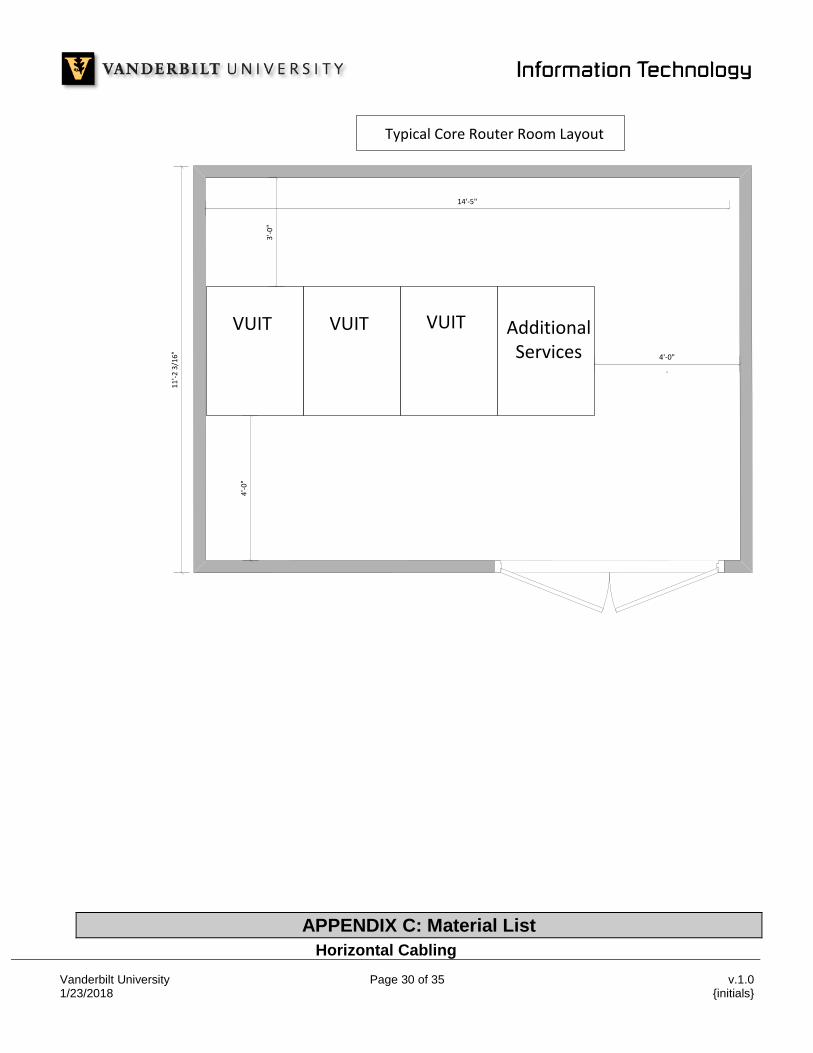
APPENDIX B: Room Layout (Continued)
Vanderbilt University Page 30 of 35 v.1.0 1/23/2018 {initials}
4'-
0"
4'-0"
.
3'-
0"
14'-5"
11
'-2
3/1
6"
VUIT VUIT VUIT AdditionalServices
Typical Core Router Room Layout
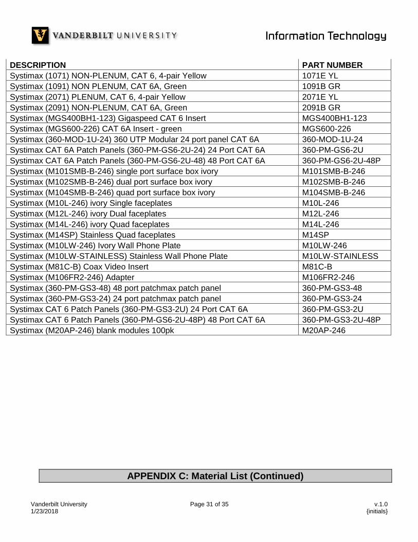
APPENDIX C: Material List
Horizontal Cabling
Vanderbilt University Page 31 of 35 v.1.0 1/23/2018 {initials}
DESCRIPTION PART NUMBER
Systimax (1071) NON-PLENUM, CAT 6, 4-pair Yellow 1071E YL
Systimax (1091) NON PLENUM, CAT 6A, Green 1091B GR
Systimax (2071) PLENUM, CAT 6, 4-pair Yellow 2071E YL
Systimax (2091) NON-PLENUM, CAT 6A, Green 2091B GR
Systimax (MGS400BH1-123) Gigaspeed CAT 6 Insert MGS400BH1-123
Systimax (MGS600-226) CAT 6A Insert - green MGS600-226
Systimax (360-MOD-1U-24) 360 UTP Modular 24 port panel CAT 6A 360-MOD-1U-24
Systimax CAT 6A Patch Panels (360-PM-GS6-2U-24) 24 Port CAT 6A 360-PM-GS6-2U
Systimax CAT 6A Patch Panels (360-PM-GS6-2U-48) 48 Port CAT 6A 360-PM-GS6-2U-48P
Systimax (M101SMB-B-246) single port surface box ivory M101SMB-B-246
Systimax (M102SMB-B-246) dual port surface box ivory M102SMB-B-246
Systimax (M104SMB-B-246) quad port surface box ivory M104SMB-B-246
Systimax (M10L-246) ivory Single faceplates M10L-246
Systimax (M12L-246) ivory Dual faceplates M12L-246
Systimax (M14L-246) ivory Quad faceplates M14L-246
Systimax (M14SP) Stainless Quad faceplates M14SP
Systimax (M10LW-246) Ivory Wall Phone Plate M10LW-246
Systimax (M10LW-STAINLESS) Stainless Wall Phone Plate M10LW-STAINLESS
Systimax (M81C-B) Coax Video Insert M81C-B
Systimax (M106FR2-246) Adapter M106FR2-246
Systimax (360-PM-GS3-48) 48 port patchmax patch panel 360-PM-GS3-48
Systimax (360-PM-GS3-24) 24 port patchmax patch panel 360-PM-GS3-24
Systimax CAT 6 Patch Panels (360-PM-GS3-2U) 24 Port CAT 6A 360-PM-GS3-2U
Systimax CAT 6 Patch Panels (360-PM-GS6-2U-48P) 48 Port CAT 6A 360-PM-GS3-2U-48P
Systimax (M20AP-246) blank modules 100pk M20AP-246
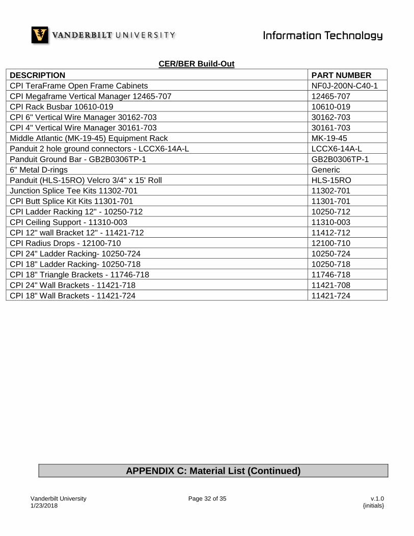
APPENDIX C: Material List (Continued)
Vanderbilt University Page 32 of 35 v.1.0 1/23/2018 {initials}
CER/BER Build-Out
DESCRIPTION PART NUMBER
CPI TeraFrame Open Frame Cabinets NF0J-200N-C40-1
CPI Megaframe Vertical Manager 12465-707 12465-707
CPI Rack Busbar 10610-019 10610-019
CPI 6" Vertical Wire Manager 30162-703 30162-703
CPI 4" Vertical Wire Manager 30161-703 30161-703
Middle Atlantic (MK-19-45) Equipment Rack MK-19-45
Panduit 2 hole ground connectors - LCCX6-14A-L LCCX6-14A-L
Panduit Ground Bar - GB2B0306TP-1 GB2B0306TP-1
6" Metal D-rings Generic
Panduit (HLS-15RO) Velcro 3/4" x 15' Roll HLS-15RO
Junction Splice Tee Kits 11302-701 11302-701
CPI Butt Splice Kit Kits 11301-701 11301-701
CPI Ladder Racking 12" - 10250-712 10250-712
CPI Ceiling Support - 11310-003 11310-003
CPI 12" wall Bracket 12" - 11421-712 11412-712
CPI Radius Drops - 12100-710 12100-710
CPI 24" Ladder Racking- 10250-724 10250-724
CPI 18" Ladder Racking- 10250-718 10250-718
CPI 18" Triangle Brackets - 11746-718 11746-718
CPI 24" Wall Brackets - 11421-718 11421-708
CPI 18" Wall Brackets - 11421-724 11421-724
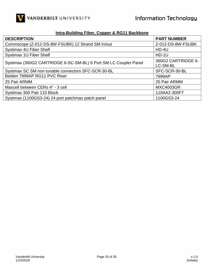
APPENDIX C: Material List (Continued)
Vanderbilt University Page 33 of 35 v.1.0 1/23/2018 {initials}
Intra-Building Fiber, Copper & RG11 Backbone
DESCRIPTION PART NUMBER
Commscope (Z-012-DS-8W-FSUBK) 12 Strand SM In/out Z-012-DS-8W-FSUBK
Systimax 4U Fiber Shelf HD-4U
Systimax 1U Fiber Shelf HD-1U
Systimax (360G2 CARTRIDGE 6-SC-SM-BL) 6 Port SM LC Coupler Panel 360G2 CARTRIDGE 6-LC-SM-BL
Systimax SC SM non tunable connectors SFC-SCR-30-BL SFC-SCR-30-BL
Belden 7999AP RG11 PVC Riser 7999AP
25 Pair ARMM 25 Pair ARMM
Maxcell between CERs 4" - 3 cell MXC4003GR
Systimax 300 Pair 110 Block 110AA2-300FT
Systimax (1100GS3-24) 24 port patchmax patch panel 1100GS3-24
Vanderbilt University Page 34 of 35 v.1.0 1/23/2018 {initials}
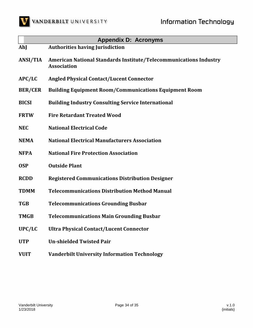
Appendix D: Acronyms
AhJ Authorities having Jurisdiction ANSI/TIA American National Standards Institute/Telecommunications Industry
Association APC/LC Angled Physical Contact/Lucent Connector
BER/CER Building Equipment Room/Communications Equipment Room BICSI Building Industry Consulting Service International FRTW Fire Retardant Treated Wood NEC National Electrical Code NEMA National Electrical Manufacturers Association NFPA National Fire Protection Association OSP Outside Plant RCDD Registered Communications Distribution Designer TDMM Telecommunications Distribution Method Manual TGB Telecommunications Grounding Busbar TMGB Telecommunications Main Grounding Busbar UPC/LC Ultra Physical Contact/Lucent Connector UTP Un-shielded Twisted Pair VUIT Vanderbilt University Information Technology
Vanderbilt University Page 35 of 35 v.1.0 1/23/2018 {initials}
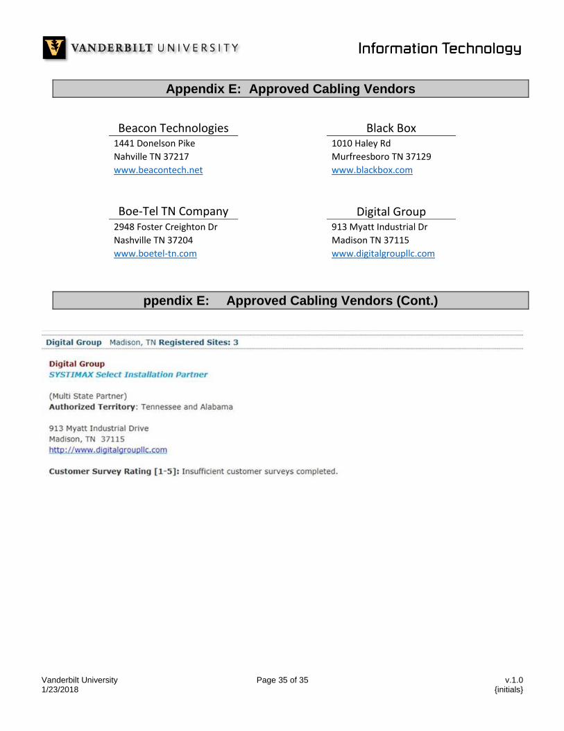
Appendix E: Approved Cabling Vendors
Beacon Technologies Black Box 1441 Donelson Pike 1010 Haley Rd
Nahville TN 37217 Murfreesboro TN 37129
www.beacontech.net www.blackbox.com
Boe-Tel TN Company Digital Group 2948 Foster Creighton Dr 913 Myatt Industrial Dr
Nashville TN 37204 Madison TN 37115
www.boetel-tn.com www.digitalgroupllc.com
ppendix E: Approved Cabling Vendors (Cont.)


![[ Pycon Korea 2017 ] Infrastructure as Code를위한 Ansible 활용](https://static.fdocument.pub/doc/165x107/5a64b7d27f8b9a88148b4905/-pycon-korea-2017-infrastructure-as-code-ansible-.jpg)