
MV Breaker
40
DEH 40368 Instructions g PowerVac ® Vacuum Circuit Breaker with ML-20 Mechanism
Transcript of MV Breaker
DEH 40368 Instructions g
PowerVac ® Vacuum Circuit Breaker
with ML-20 Mechanism
2
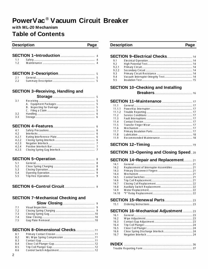
PowerVac ® Vacuum Circuit Breaker
with ML-20 Mechanism
Table of Contents
Description Page
SECTION 1−−−−Introduction ............................................ 4
1.1 Safety .............................................................................. 4 1.2 Maintenance ................................................................... 4
SECTION 2−−−−Description............................................... 5
2.1 General............................................................................ 5 2.2 Summary Description ...................................................... 5
SECTION 3−−−−Receiving, Handling and
Storage ...................................................... 5 3.1 Receiving ........................................................................ 5 A. Equipment Packages................................................. 5 B. Inspecting for Damage .............................................. 5 C. Filing a Claim ............................................................. 5 3.2 Handling .......................................................................... 6 3.3 Storage............................................................................ 6
SECTION 4−−−−Features...................................................... 6
4.1 Safety Precautions........................................................... 6 4.2 Interlocks ......................................................................... 6 4.2.1 Rating Interference Plate................................................. 6 4.2.2 Closing Spring Interlock ................................................... 6 4.2.3 Negative Interlock............................................................ 7 4.2.4 Positive Interlock Bar....................................................... 7 4.2.5 Closing Spring Gag Interlock............................................ 7
SECTION 5−−−−Operation .................................................. 8
5.1 General............................................................................ 8 5.2 Close Spring Charging ..................................................... 8 5.3 Closing Operation............................................................ 8 5.4 Opening Operation.......................................................... 9 5.5 Trip-free Operation.......................................................... 9
SECTION 6−−−−Control Circuit....................................... 9
SECTION 7−−−−Mechanical Checking and Slow Closing ......................................... 9
7.1 Visual Inspection.............................................................. 9 7.2 Closing Spring Charging .................................................. 9 7.3 Closing Spring Gag ..........................................................10 7.4 Slow Closing....................................................................10 7.5 Gag Plate Removal..........................................................10
SECTION 8−−−−Dimensional Checks.........................11
8.1 Primary Contact Erosion ..................................................11 8.2 ML Wipe Spring Compression ........................................11 8.3 Contact Gap ....................................................................11
8.4 Close Coil Plunger Gap....................................................12 8.5 Trip Coil Plunger Gap.......................................................12 8.6 Control Switch Adjustment..............................................12
Description Page
SECTION 9−−−−Electrical Checks................................. 14
9.1 Electrical Operation......................................................... 14 9.2 High Potential Test.......................................................... 14 9.2.1 Primary Circuit................................................................. 14 9.2.2 Secondary Circuit ............................................................ 14 9.3 Primary Circuit Resistance .............................................. 14 9.4 Vacuum Interrupter Integrity Test.................................... 14 9.5 Insulation Test................................................................. 15
SECTION 10−−−−Checking and Installing Breakers................................................. 16
SECTION 11−−−−Maintenance ....................................... 17 11.1 General ........................................................................... 17 11.1.1 PowerVac Interrupter ...................................................... 17 11.1.2 Trouble Reporting ........................................................... 17 11.2 Service Conditions .......................................................... 17 11.3 Fault Interruptions ........................................................... 17 11.4 Contact Erosion............................................................... 17 11.5 Transfer Finger Wear ...................................................... 17 11.6 Mechanism ..................................................................... 17 11.7 Primary Insulation Parts................................................... 17 11.8 Lubrication ...................................................................... 18 11.9 Recommended Maintenance.......................................... 18
SECTION 12−−−−Timing ...................................................... 19
SECTION 13−−−−Opening and Closing Speed .. 20
SECTION 14−−−−Repair and Replacement........... 21 14.1 General ........................................................................... 21 14.2 Replacement of Interrupter Assemblies ......................... 21 14.3 Primary Disconnect Fingers ............................................ 21 14.4 Mechanism ..................................................................... 21 14.5 Control Switches............................................................. 21 14.6 Trip Coil Replacement..................................................... 21 14.7 Closing Coil Replacement............................................... 22 14.8 Auxiliary Switch Replacement......................................... 22 14.9 Motor Replacement........................................................ 22 14.10 “Y” Relay Replacement................................................... 22
SECTION 15−−−−Renewal Parts .................................... 23 15.1 Ordering Instructions....................................................... 23
SECTION 16−−−−Mechanical Adjustment ............ 23 16.1 General ........................................................................... 23 16.2 Wipe Adjustment ............................................................ 23 16.3 Contact Gap Adjustment ................................................. 23 16.4 Trip Coil Plunger.............................................................. 24 16.5 Close Coil Plunger........................................................... 24 16.6 Close Spring Discharge Interlock..................................... 24
16.7 Negative Interlock ........................................................... 24
INDEX ........................................................................................ 36
Trouble Reporting Form................................................................ 37
3
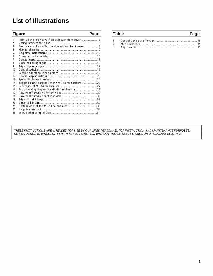
List of Illustrations
Figure Page
1 Front view of PowerVac® breaker with front cover.................... 6 2 Rating interference plate........................................................... 6 3 Front view of PowerVac breaker without front cover ................ 8 4 Manual charging........................................................................ 9 5 Gag plate installation .................................................................10 6 Operating rod assembly ............................................................10 7 Contact gap ...............................................................................11 8 Close coil plunger gap ...............................................................12 9 Trip coil plunger gap ..................................................................12 10 Control switches .......................................................................13 11 Sample operating speed graphs................................................19 12 Contact gap adjustment ............................................................20 13 Spring discharge interlock .........................................................24 14 Toggle linkage positions of the ML-18 mechanism ...................25 15 Schematic of ML-18 mechanism...............................................27 16 Typical wiring diagram for ML-18 mechanism...........................29 17 PowerVac® breaker left-front view ............................................30 18 PowerVac® breaker right-rear view............................................30 19 Trip coil and linkage...................................................................31 20 Close coil linkage.......................................................................32 21 Bottom view of the ML-18 mechanism.....................................33 22 Negative interlock .....................................................................34 23 Wipe spring compression..........................................................34
Table Page
1 Control Device and Voltage..................................................... 18 2 Measurements ....................................................................... 35 3 Adjustments............................................................................ 35
THESE INSTRUCTIONS ARE INTENDED FOR USE BY QUALIFIED PERSONNEL FOR INSTRUCTION AND MAINTENANCE PURPOSES. REPRODUCTION IN WHOLE OR IN PART IS NOT PERMITTED WITHOUT THE EXPRESS PERMISSION OF GENERAL ELECTRIC.
4
PowerVac
® Vacuum Circuit Breaker with ML-20 Mechanism
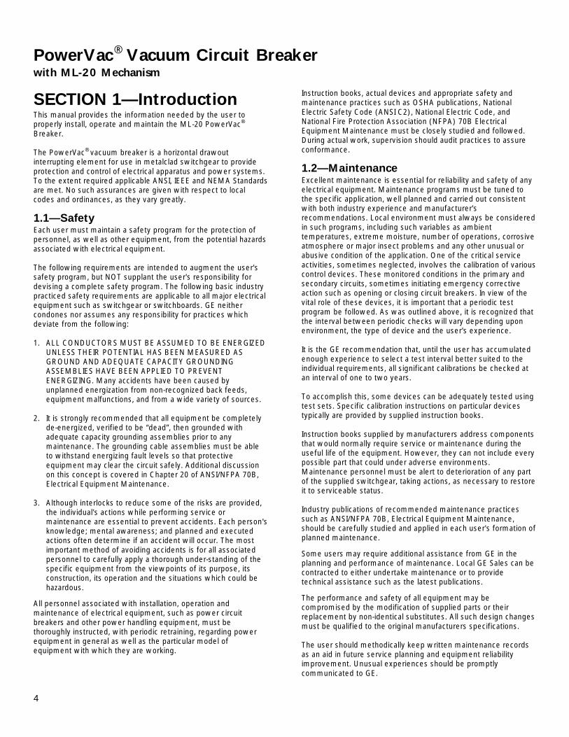
SECTION 1—Introduction This manual provides the information needed by the user to properly install, operate and maintain the ML-20 PowerVac® Breaker. The PowerVac® vacuum breaker is a horizontal drawout interrupting element for use in metalclad switchgear to provide protection and control of electrical apparatus and power systems. To the extent required applicable ANSI, IEEE and NEMA Standards are met. No such assurances are given with respect to local codes and ordinances, as they vary greatly.
1.1—Safety Each user must maintain a safety program for the protection of personnel, as well as other equipment, from the potential hazards associated with electrical equipment. The following requirements are intended to augment the user's safety program, but NOT supplant the user's responsibility for devising a complete safety program. The following basic industry practiced safety requirements are applicable to all major electrical equipment such as switchgear or switchboards. GE neither condones nor assumes any responsibility for practices which deviate from the following: 1. ALL CONDUCTORS MUST BE ASSUMED TO BE ENERGIZED
UNLESS THEIR POTENTIAL HAS BEEN MEASURED AS GROUND AND ADEQUATE CAPACITY GROUNDING ASSEMBLIES HAVE BEEN APPLIED TO PREVENT ENERGIZING. Many accidents have been caused by unplanned energization from non-recognized back feeds, equipment malfunctions, and from a wide variety of sources.
2. It is strongly recommended that all equipment be completely
de-energized, verified to be “dead”, then grounded with adequate capacity grounding assemblies prior to any maintenance. The grounding cable assemblies must be able to withstand energizing fault levels so that protective equipment may clear the circuit safely. Additional discussion on this concept is covered in Chapter 20 of ANSI/NFPA 70B, Electrical Equipment Maintenance.
3. Although interlocks to reduce some of the risks are provided,
the individual's actions while performing service or maintenance are essential to prevent accidents. Each person's knowledge; mental awareness; and planned and executed actions often determine if an accident will occur. The most important method of avoiding accidents is for all associated personnel to carefully apply a thorough under-standing of the specific equipment from the viewpoints of its purpose, its construction, its operation and the situations which could be hazardous.
All personnel associated with installation, operation and maintenance of electrical equipment, such as power circuit breakers and other power handling equipment, must be thoroughly instructed, with periodic retraining, regarding power equipment in general as well as the particular model of equipment with which they are working.
Instruction books, actual devices and appropriate safety and maintenance practices such as OSHA publications, National Electric Safety Code (ANSI C2), National Electric Code, and National Fire Protection Association (NFPA) 70B Electrical Equipment Maintenance must be closely studied and followed. During actual work, supervision should audit practices to assure conformance.
1.2—Maintenance Excellent maintenance is essential for reliability and safety of any electrical equipment. Maintenance programs must be tuned to the specific application, well planned and carried out consistent with both industry experience and manufacturer's recommendations. Local environment must always be considered in such programs, including such variables as ambient temperatures, extreme moisture, number of operations, corrosive atmosphere or major insect problems and any other unusual or abusive condition of the application. One of the critical service activities, sometimes neglected, involves the calibration of various control devices. These monitored conditions in the primary and secondary circuits, sometimes initiating emergency corrective action such as opening or closing circuit breakers. In view of the vital role of these devices, it is important that a periodic test program be followed. As was outlined above, it is recognized that the interval between periodic checks will vary depending upon environment, the type of device and the user's experience. It is the GE recommendation that, until the user has accumulated enough experience to select a test interval better suited to the individual requirements, all significant calibrations be checked at an interval of one to two years. To accomplish this, some devices can be adequately tested using test sets. Specific calibration instructions on particular devices typically are provided by supplied instruction books. Instruction books supplied by manufacturers address components that would normally require service or maintenance during the useful life of the equipment. However, they can not include every possible part that could under adverse environments. Maintenance personnel must be alert to deterioration of any part of the supplied switchgear, taking actions, as necessary to restore it to serviceable status. Industry publications of recommended maintenance practices such as ANSI/NFPA 70B, Electrical Equipment Maintenance, should be carefully studied and applied in each user's formation of planned maintenance.
Some users may require additional assistance from GE in the planning and performance of maintenance. Local GE Sales can be contracted to either undertake maintenance or to provide technical assistance such as the latest publications.
The performance and safety of all equipment may be compromised by the modification of supplied parts or their replacement by non-identical substitutes. All such design changes must be qualified to the original manufacturers specifications. The user should methodically keep written maintenance records as an aid in future service planning and equipment reliability improvement. Unusual experiences should be promptly communicated to GE.

5
SECTION 2—Description
2.1—General This section contains a description of the PowerVac® vacuum circuit breaker. It also describes the functions of the electrical and mechanical systems.
2.2—Summary Description The PowerVac® vacuum circuit breaker uses sealed vacuum power interrupters to establish and interrupt a primary circuit. Primary connections to the associated metalclad switchgear are made by horizontal bars and disconnect fingers, electrically and mechanically connected to the vacuum interrupters. Molded interrupter supports, one per phase on a three-phase circuit breaker, provide mountings for the primary bars, interrupters, current transfer fingers, and heat dissipation fins (where used). The operating mechanism provides direct motion at each phase location in order to move the movable contact of the vacuum interrupters from an open position to a spring-loaded closed position and then back to the open position on command.
The ML-20 mechanism is of the stored-energy type and use a gear motor to charge a closing spring. During a closing operation, the energy stored in the closing spring is used to close the vacuum interrupter contacts, compress the wipe springs which load the contacts, charge the opening springs, and overcome bearing and other friction forces, The energy then stored in the wipe springs and opening springs will open the contacts during an opening operation. Closing and opening operations are controlled electrically by the metalclad switchgear or remote relaying. Mechanical control is provided by manual close and trip buttons on the circuit breaker. The closing spring may be manually charged, and a method for slow-closing the primary contacts is available. The mechanism will operate at the ac or dc voltage indicated on the circuit breaker nameplate. Mechanical and electrical interlocks are provided and are described in para 4.2, Interlocks
SECTION 3—Receiving, Handling and Storage
3.1—Receiving A. Equipment Packages Every package leaving the factory is plainly marked with the case number, requisition number, and customer’s order number. If the equipment has been split for shipment, the section numbers of the equipment enclosed in each shipping package are identified.
NOTE: To avoid loss of any parts when unpacking, the contents of each container should be carefully checked against the packing list before discarding the packing material.
Contents of each shipping package are listed on the Master Packing List. In addition, this list includes the number of the shipping crate in which miscellaneous parts needed to install and operate equipment (such as hardware, contact lubricant, touch-up paint, breaker closing devices, etc.) are located. Normally, such devices are packed in a cardboard carton.
B. Inspecting for Damage All equipment leaving the factory is carefully inspected and packed by personnel experienced in the proper handling and packing of electrical equipment. Upon receipt of any equipment, immediately perform a visual inspection to ascertain if any damage has been sustained in shipping or if there are any loose parts.
C. Filing a Claim If any damage is evident, or indication of rough handling is visible, file a claim for damage at once with the transportation company and notify the nearest GE Company Sales Office immediately. Information on damaged parts, part number, case number, requisition number, etc., should accompany the claim.
3.2—Handling When lifting the breaker, use of the specially designed lift truck is recommended. If it is necessary to lift the breaker with a hoist use four 1/2 inch diameter hooks rated at least 500 pounds each. Lifting holes are provided in the four corners of the frame members. (See figure 2) Use a spreader wider than the breaker to prevent slings from contacting the interrupter supports.
3.3—Storage It is recommended that the breaker be put immediately in its permanent location. If this is not possible, the following precautions must be taken to assure proper breaker storage.
1. The breaker should be protected against condensation, preferably by storing it in a warm dry room of moderate temperature such as 40° - 100° F. Circuit breakers for outdoor metalclad switchgear should be stored in the equipment only when power is available and the heaters are in operation to prevent condensation.
2. The breaker should be stored in a clean location, free from corrosive gases or fumes; particular care, for example, should be taken to protect the equipment from moisture and cement dust, as this combination is present at construction sites and has a very corrosive effect on many parts.
3. Rollers, latches, etc., of the operating mechanism should be coated with 0282A2048P009 grease to prevent rusting.
If the breaker is stored for any length of time, it should be inspected periodically to see that rusting has not started and to ensure good mechanical condition. Should the breaker be stored under unfavorable atmospheric conditions, it should be cleaned and dried out before being placed in service.
6
SECTION 4—Features
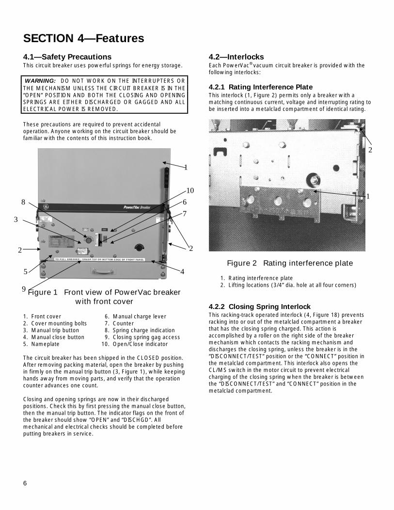
4.1—Safety Precautions This circuit breaker uses powerful springs for energy storage. WARNING: DO NOT WORK ON THE INTERRUPTERS OR THE MECHANISM UNLESS THE CIRCUIT BREAKER IS IN THE “OPEN” POSITION AND BOTH THE CLOSING AND OPENING SPRINGS ARE EITHER DISCHARGED OR GAGGED AND ALL ELECTRICAL POWER IS REMOVED. These precautions are required to prevent accidental operation. Anyone working on the circuit breaker should be familiar with the contents of this instruction book.
Figure 1 Front view of PowerVac breaker
with front cover 1. Front cover 6. Manual charge lever 2. Cover mounting bolts 7. Counter 3. Manual trip button 8. Spring charge indication 4. Manual close button 9. Closing spring gag access 5. Nameplate 10. Open/Close indicator The circuit breaker has been shipped in the CLOSED position. After removing packing material, open the breaker by pushing in firmly on the manual trip button (3, Figure 1), while keeping hands away from moving parts, and verify that the operation counter advances one count. Closing and opening springs are now in their discharged positions. Check this by first pressing the manual close button, then the manual trip button. The indicator flags on the front of the breaker should show “OPEN” and “DISCHGD”. All mechanical and electrical checks should be completed before putting breakers in service.
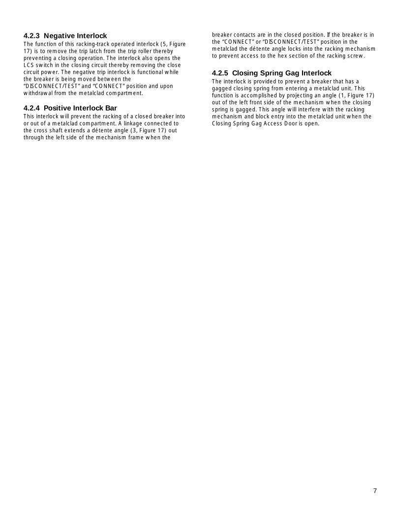
4.2—Interlocks Each PowerVac® vacuum circuit breaker is provided with the following interlocks: 4.2.1 Rating Interference Plate This interlock (1, Figure 2) permits only a breaker with a matching continuous current, voltage and interrupting rating to be inserted into a metalclad compartment of identical rating.
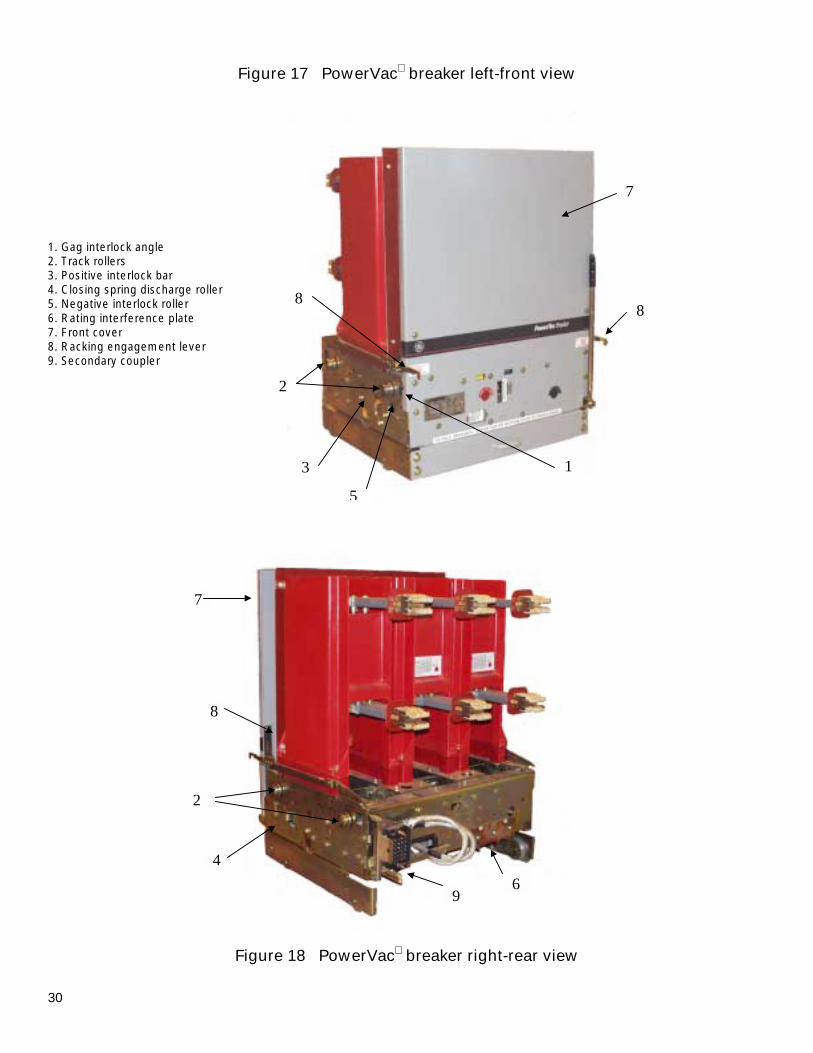
Figure 2 Rating interference plate 1. Rating interference plate 2. Lifting locations (3/4” dia. hole at all four corners) 4.2.2 Closing Spring Interlock This racking-track operated interlock (4, Figure 18) prevents racking into or out of the metalclad compartment a breaker that has the closing spring charged. This action is accomplished by a roller on the right side of the breaker mechanism which contacts the racking mechanism and discharges the closing spring, unless the breaker is in the “DISCONNECT/TEST” position or the “CONNECT” position in the metalclad compartment. This interlock also opens the CL/MS switch in the motor circuit to prevent electrical charging of the closing spring when the breaker is between the “DISCONNECT/TEST” and “CONNECT” position in the metalclad compartment.
2
1
1
10 6 7
2
4
8
3
2
5
9
7
4.2.3 Negative Interlock The function of this racking-track operated interlock (5, Figure 17) is to remove the trip latch from the trip roller thereby preventing a closing operation. The interlock also opens the LCS switch in the closing circuit thereby removing the close circuit power. The negative trip interlock is functional while the breaker is being moved between the “DISCONNECT/TEST” and “CONNECT” position and upon withdrawal from the metalclad compartment. 4.2.4 Positive Interlock Bar This interlock will prevent the racking of a closed breaker into or out of a metalclad compartment. A linkage connected to the cross shaft extends a détente angle (3, Figure 17) out through the left side of the mechanism frame when the
breaker contacts are in the closed position. If the breaker is in the “CONNECT” or “DISCONNECT/TEST” position in the metalclad the détente angle locks into the racking mechanism to prevent access to the hex section of the racking screw.
4.2.5 Closing Spring Gag Interlock The interlock is provided to prevent a breaker that has a gagged closing spring from entering a metalclad unit. This function is accomplished by projecting an angle (1, Figure 17) out of the left front side of the mechanism when the closing spring is gagged. This angle will interfere with the racking mechanism and block entry into the metalclad unit when the Closing Spring Gag Access Door is open.
8
SECTION 5—Operation
5.1—General The PowerVac® vacuum circuit breaker uses sealed vacuum power interrupters to establish and interrupt a primary circuit. Primary connections to the associated metalclad switchgear are made by horizontal bars and disconnect fingers, electrically and mechanically connected to the vacuum interrupters. Molded interrupter supports, one per phase on a three-phase circuit breaker, provide mountings for the primary bars, interrupters, current transfer fingers, and heat dissipation fins (where used). The operating mechanism provides direct motion at each phase location in order to move the lower contact of the vacuum interrupters from an open position to a spring-loaded closed position and then back to the open position on command.
The ML-20 mechanism (Figure 15) is of the stored-energy type and uses a gearmotor to charge a closing spring. During a closing operation, the energy stored in the closing spring is used to close the vacuum interrupter contacts, compress the wipe springs which load the contacts, charge the opening spring, and overcome bearing and other friction forces, The energy then stored in the wipe springs and opening spring will open the contacts during an opening operation.
Closing and opening operations are controlled electrically by the metalclad switchgear or remote relaying. Mechanical control is provided by manual close and trip buttons on the circuit breaker. The closing spring may be manually charged, and a method for slow-closing the primary contacts is available. The mechanism will operate at the ac or dc voltage indicated on the circuit breaker nameplate.
5.2—Close Spring Charging Figure 15 shows a front view of the ML-20 in a schematic form. The primary contacts are open and the closing spring is charged. The closing spring charging system consists of a closing spring (1, view B) mounted on the left side of the breaker and the electrical charging system mounted on the right side of the breaker. Both components are fastened to the cam shaft (2, view B). A manual charging system (3, view A) is provided so that the mechanism can be slow closed and the closing spring can be charged without electrical control power.
Spring charging is accomplished electrically by a rotating eccentric on the output shaft of the gear motor driving pivoted charging arms (4, view C) which oscillate about the centerline of a ratchet wheel (5, view C). A driving pawl (6, view C), mounted within the charging arms, oscillates with the charging arms. Starting from its rear-most position, as the charging arms rotate forward, a spring forces engagement of the driving pawl with a tooth of the ratchet wheel. The ratchet wheel is advanced by the rotating charging arms and pawl assembly. Advancement of one tooth spacing is provided for each oscillation of the system. The ratchet motion is restricted to one direction by a spring-loaded holding pawl that prevents the ratchet wheel from going backwards as the charging arms oscillate back to pick up the next tooth. Thirteen complete cycles of the charging arms are needed for a full charge of the closing spring. The efficient, compact gear motor accomplishes this action in about three seconds. When the charging cycle is complete, the ratchet wheel is positioned so
that three missing teeth adjacent to the driving pawl and any motor overspin will not drive the ratchet wheel, thus preventing damage to the system.
When the spring is completely charged, the assembly is retained in that position by the close latch, until it is desired to close the circuit breaker.
The closing coil cannot be electrically energized unless the closing spring is completely charged. This action is prevented by the 52/CHG switch in the closing circuit.
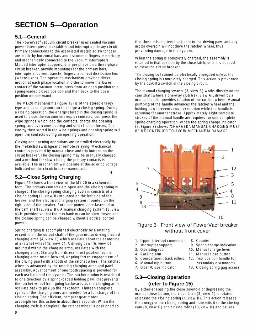
The manual charging system (3, view A) works directly on the cam shaft where a one-way clutch (7, view A), driven by a manual handle, provides rotation of the ratchet wheel. Manual pumping of the handle advances the ratchet wheel and the holding pawl prevents counter-rotation while the handle is returning for another stroke. Approximately eight complete strokes of the manual handle are required for one complete spring-charging operation. When the spring charge indicator (9, Figure 3) shows “CHARGED”, MANUAL CHARGING MUST BE DISCONTINUED TO AVOID MECHANISM DAMAGE.
Figure 3 Front view of PowerVac® breaker without front cover
1. Upper interrupt connection 8. Counter 2. Interrupter support 9. Spring charge indication 3. Operating rod 10. Manual charge lever 4. Racking arm 11. Manual close button 5. Compartment track rollers 12. Test position handle for 6. Manual trip button secondary disconnects 7. Open/Close indicator 13. Closing spring gag access
5.3—Closing Operation (refer to Figure 15) By either energizing the close solenoid or depressing the manual close button, the close latch (8, view C) is rotated, releasing the closing spring (1, view B). This action releases the energy in the closing spring and transmits it to the closing cam (9, view D) and closing roller (10, view D) and causes
1
12
2
3
4 5
10
11 8
13
96
9
7
54
9
the linkage to rise until the prop (11, view D) can slip under the close roller (10, view D) and hold the linkage in place. As the linkage moves, the output crank (12, view D) rotates the cross shaft (13, view D) which in turn rotates the phase bell cranks and compresses the two opening springs (15, view E) on poles 1 and 3, this closes the vacuum interrupters, and compresses the three wipe springs (16, view E) on each pole. The rotation of the cross shaft (13, view D) also changes the auxiliary switch (7, view D) position. The position flag on the front panel will then indicate “CLOSED”. After the breaker is closed, the charging motor is again energized and the closing spring is charged as described under “CLOSE SPRING CHARGING”. Spring charging is possible when the breaker is in the closed position because the linkage is held in place by the prop.
5.4—Opening Operation (refer to Figure 15) By either energizing the trip solenoid or depressing the manual trip button (23, view B), the trip latch (19, view D) is rotated, permitting the linkage to collapse and the vacuum
interrupter contacts to open under the force of the wipe springs (16, view E) and opening springs (15, view E). At the end of the opening stroke, the center phase wipe spring assembly hits a stop block on the frame that limits overtravel and rebound. Rotation of the cross shaft from the closed to the open position operates the auxiliary switch (17, view D) which opens the trip coil circuit. If the closing spring has been recharged, the linkage will be reset and the trip latch will be in place on the trip roller, ready for another closing operation.
5.5—Trip-free Operation The linkage is mechanically trip free in any location on the closing stroke. Electrically energizing the trip coil while closing will, after the auxiliary switch contacts change position, rotate the trip latch and permit the circuit breaker to open fully.
The linkage will reset as in a normal open operation, and the closing spring will recharge as described under SPRING CHARGING.
SECTION 6—Electric Control circuit
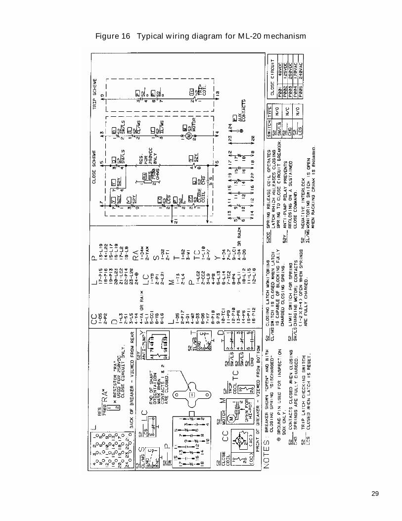
A typical PowerVac® circuit breaker ML-20 mechanism wiring diagram is shown in Figure 16. Check the wiring diagram supplied with the actual circuit breaker for its wiring.
The close spring-charging motor circuit is established through the CL/MS (close latch monitor switch) switch if the close latch is reset the SM/LS (spring motor limit switch) if the closing spring is discharged and the IL/MS (Negative Interlock Monitoring Switch). When the closing spring is charged, the SM/LS interrupts the circuit.
The close coil circuit is established through two normally closed 52Y relay contacts, and the latch-checking switch LCS, if the trip latch is reset. An auxiliary switch contact 52b is also in series with the close coil and closes when the breaker is
open and opens when the breaker is closed. During a close operation, cam rotation closes the SM/LS contact allowing the 52Y relay to be energized; opening its contacts in the close coil circuit and sealing itself in through one of its own contacts to the close signal. This seal-in action prevents re-closing on a sustained close command as the close signal must be removed to drop out the Y relay, and reestablish the close circuit, thereby providing an anti-pump feature.
Circuit breaker mounted auxiliary switch contacts not used in the control circuit are bought out for control and indication functions. The metalclad equipment may provide a breaker operated stationary auxiliary switch for additional contacts (3, 6 or 10 stages are available).
SECTION 7—Mechanical Checking and Slow Closing
7.1—Visual Inspection Visually inspect the circuit breaker for any signs of damage or loose hardware.
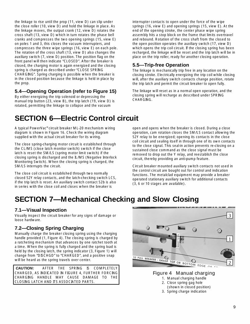
7.2—Closing Spring Charging Manually charge the breaker closing spring using the charging handle provided (1, Figure 4). The closing spring is charged by a ratcheting mechanism that advances by one ratchet tooth at a time. When the spring is fully charged and the spring load is held by the closing latch, the spring indicator (3, Figure 1) will change from “DISCHGD” to “CHARGED”, and a positive snap will be heard as the spring travels over center.
CAUTION: AFTER THE SPRING IS COMPLETELY CHARGED, AS INDICATED IN FIGURE 4, FURTHER FORCING CHARGING HANDLE MAY CAUSE DAMAGE TO THE CLOSING LATCH AND ITS ASSOCIATED PARTS.
Figure 4 Manual charging 1. Manual charging handle 2. Close spring gag hole (shown in closed position) 3. Spring charge indication
3
1
2
10
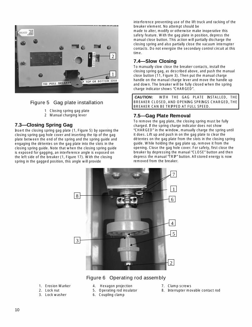
Figure 5 Gag plate installation
1 Closing spring gag plate 2 Manual charging lever
7.3—Closing Spring Gag Insert the closing spring gag plate (1, Figure 5) by opening the closing spring gag hole cover and inserting the tip of the gag plate between the end of the spring and the spring guide and engaging the détentes on the gag plate into the slots in the closing spring guide. Note that when the closing spring guide is exposed for gagging, an interference angle is exposed on the left side of the breaker (1, Figure 17). With the closing spring in the gagged position, this angle will provide
interference preventing use of the lift truck and racking of the breaker element. No attempt should be made to alter, modify or otherwise make inoperative this safety feature. With the gag plate in position, depress the manual close button. This action will partially discharge the closing spring and also partially close the vacuum interrupter contacts. Do not energize the secondary control circuit at this time.
7.4—Slow Closing To manually slow close the breaker contacts, install the closing spring gag, as described above, and push the manual close button (11, Figure 3). Then put the manual charge handle on the manual charge lever and move the handle up and down. The breaker will be fully closed when the spring charge indicator shows “CHARGED”.
CAUTION: WITH THE GAG PLATE INSTALLED, THE BREAKER CLOSED, AND OPENING SPRINGS CHARGED, THE BREAKER CAN BE TRIPPED AT FULL SPEED.
7.5—Gag Plate Removal To remove the gag plate, the closing spring must be fully charged. If the spring charge indicator does not show “CHARGED” in the window, manually charge the spring until it does. Lift up and push in on the gag plate to clear the détentes on the gag plate from the slots in the closing spring guide. While holding the gag plate up, remove it from the opening. Close the gag hole cover. For safety, first close the breaker by depressing the manual “CLOSE” button and then depress the manual “TRIP” button. All stored energy is now removed from the breaker.
Figure 6 Operating rod assembly
1. Erosion Marker 4. Hexagon projection 7. Clamp screws 2. Lock nut 5. Operating rod insulator 8. Interrupter movable contact rod 3. Lock washer 6. Coupling clamp
2
1
8
7
6
5
4
3
2
1
11
SECTION 8—Dimensional Checks With the breaker closed and the gag plate installed, perform the following dimensional checks.
8.1—Primary Contact Erosion In the closed position, the erosion marker (1, Figure 6) below the bus bar is aligned with a reference mark on the interrupter’s movable stem. As contact erosion occurs, the erosion mark will move upward away from the erosion pointer. When the seribed band on the interrupter’s movable stem is completely above the top surface of the pointer, 1/8 inch erosion has occurred and the interrupter should be replaced.
8.2—ML-20 Wipe Spring Compression With the breaker closed and the closing spring gagged, measure with a feeler gauge and record the distance between the bellville washer and the trunion between the bell crank arms.
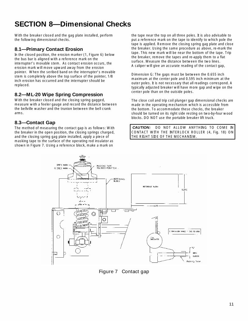
8.3—Contact Gap The method of measuring the contact gap is as follows: With the breaker in the open position, the closing springs charged, and the closing spring gag plate installed, apply a piece of masking tape to the surface of the operating rod insulator as shown in Figure 7. Using a reference block, make a mark on
the tape near the top on all three poles. It is also advisable to put a reference mark on the tape to identify to which pole the tape is applied. Remove the closing spring gag plate and close the breaker. Using the same procedure as above, re-mark the tape. This new mark will be near the bottom of the tape. Trip the breaker, remove the tapes and re-apply them to a flat surface. Measure the distance between the two lines. A caliper will give an accurate reading of the contact gap, Dimension G: The gaps must be between the 0.655 inch maximum at the center pole and 0.595 inch minimum at the outer poles. It is not necessary that all readings correspond. A typically adjusted breaker will have more gap and wipe on the center pole than on the outside poles. The close coil and trip coil plunger gap dimensional checks are made in the operating mechanism which is accessible from the bottom. To accommodate these checks, the breaker should be turned on its right side resting on two-by-four wood blocks. DO NOT use the portable breaker lift truck.
CAUTION: DO NOT ALLOW ANYTHING TO COME IN CONTACT WITH THE INTERLOCK ROLLER (4, Fig. 18) ON THE RIGHT SIDE OF THE MECHANISM.
Figure 7 Contact gap
12
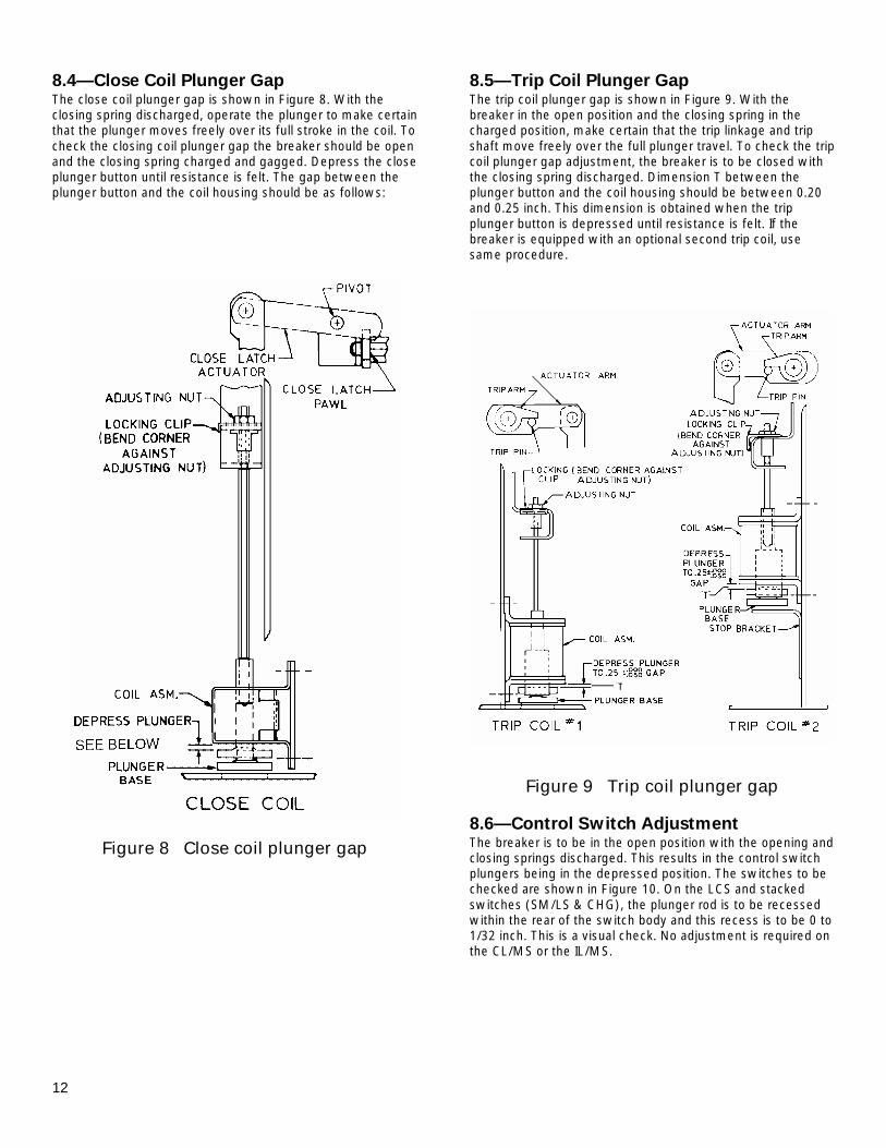
8.4—Close Coil Plunger Gap The close coil plunger gap is shown in Figure 8. With the closing spring discharged, operate the plunger to make certain that the plunger moves freely over its full stroke in the coil. To check the closing coil plunger gap the breaker should be open and the closing spring charged and gagged. Depress the close plunger button until resistance is felt. The gap between the plunger button and the coil housing should be as follows:
Figure 8 Close coil plunger gap
8.5—Trip Coil Plunger Gap The trip coil plunger gap is shown in Figure 9. With the breaker in the open position and the closing spring in the charged position, make certain that the trip linkage and trip shaft move freely over the full plunger travel. To check the trip coil plunger gap adjustment, the breaker is to be closed with the closing spring discharged. Dimension T between the plunger button and the coil housing should be between 0.20 and 0.25 inch. This dimension is obtained when the trip plunger button is depressed until resistance is felt. If the breaker is equipped with an optional second trip coil, use same procedure.
Figure 9 Trip coil plunger gap
8.6—Control Switch Adjustment The breaker is to be in the open position with the opening and closing springs discharged. This results in the control switch plungers being in the depressed position. The switches to be checked are shown in Figure 10. On the LCS and stacked switches (SM/LS & CHG), the plunger rod is to be recessed within the rear of the switch body and this recess is to be 0 to 1/32 inch. This is a visual check. No adjustment is required on the CL/MS or the IL/MS.
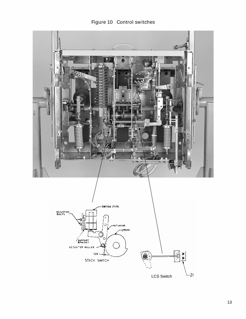
Figure 10 Control switches
LCS Switch
13
14
SECTION 9—Electrical Checks
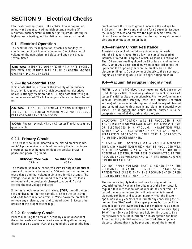
Electrical checking consists of electrical breaker operation primary and secondary wiring high-potential testing (if required), primary circuit resistance (if required). Interrupter high-potential testing, and insulation resistance to ground.
9.1—Electrical Operation To check the electrical operation, attach a secondary test coupler to the circuit breaker connector. Check the control voltage on the nameplate and close and open the breaker several times.
CAUTION: REPEATED OPERATIONS AT A RATE EXCEED- ING TWO PER MINUTE MAY CAUSE CHARGING MOTOR OVERHEATING AND FAILURE.
9.2—High-Potential Test If high potential tests to check the integrity of the primary insulation is required, the AC high potential test described below is strongly recommended. DC high potential testing is not recommended. The following procedure must be adhered to. CAUTION: IF DC HIGH POTENTIAL TESTING IS REQUIRED, THE DC HIGH POTENTIAL MACHINE MUST NOT PRODUCE PEAK VOLTAGES EXCEEDING 50 KV. NOTE: Always recheck with an AC tester if initial results are questionable.
9.2.1 Primary Circuit The breaker should be hipotted in the closed breaker mode. An AC hipot machine capable of producing the test voltages shown below may be used to hipot the breaker phase to phase and phase to ground.
BREAKER VOLTAGE AC TEST VOLTAGE 27.0 kV 45 kV
The machine should be connected with its output potential at zero and the voltage increased at 500 volts per second to the test voltage and that voltage maintained for 60 seconds. The voltage should then be returned to zero and the test leads removed and the breaker discharged to ground. Do not exceed the test voltage indicated.
If the test should experience a failure, STOPSTOPSTOPSTOP, turn off the test set and discharge the test sample. 1. Check the test setup and leads for connection errors. 2. Wipe down the breaker to remove any moisture, dust and contamination. 3. Retest the breaker at the proper test voltage.
9.2.2 Secondary Circuit Prior to hipotting the breaker secondary circuit, disconnect the motor leads and thread a wire connecting all secondary disconnect pins except #24, the ground pin. Connect the hipot
machine from this wire to ground. Increase the voltage to 1125 volts (rms) 60 Hz and maintain for 60 seconds. Reduce the voltage to zero and remove the hipot machine from the circuit. Remove the wire connecting the secondary disconnect pins and reconnect the motor leads.
9.3—Primary Circuit Resistance A resistance check of the primary circuit may be made with the breaker closed. Use a low resistance measuring instrument rated 100 amperes which measures in microhms. The 100 ampere reading should be 25 or less microhms for a 600/1200 or 2000 amp. Breaker, when connected across the upper and lower primary bars on the breaker side of the disconnect fingers. Do not connect directly to the disconnect fingers as errors may occur due to finger spring pressure
9.4—Vacuum Interrupter Integrity Test
NOTE: Use of a DC hipot is not recommended, but can be used for quick field checks only. Always recheck with an AC tester if initial results are questionable. Prior to performing any vacuum interrupter integrity test, the outside (external surface) of the vacuum interrupters should be wiped clean of any contaminates with a non-linting cloth or industrial type wiper. This is critical: the entire external surface is to be completely free of all dirt, debris, dust, oil, etc.
CAUTION: X-RADIATION WILL BE PRODUCED IF AN ABNORMALLY HIGH VOLTAGE IS APPLIED ACROSS A PAIR OF ELECTRODES IN A VACUUM. X-RADIATION WILL INCREASE AS VOLTAGE INCREASES AND/OR AS CONTACT SEPARATION DECREASES. ONLY TEST A CORRECTLY-ADJUSTED CIRCUIT BREAKER.
DURING A HIGH POTENTIAL OR A VACUUM INTEGRITY TEST, ANY X-RADIATION WHICH MAY BE PRODUCED WILL NOT BE HAZARDOUS AT A DISTANCE SAFE FOR HIGH POTENTIAL TESTING, IF THE TEST IS CONDUCTED AT THE RECOMMENDED VOLTAGE AND WITH THE NORMAL OPEN CIRCUIT BREAKER GAP.
DO NOT APPLY VOLTAGE THAT IS HIGHER THAN THE RECOMMENDED VALUE. DO NOT USE CONTACT SEPA-RATION THAT IS LESS THAN THE RECOMMENDED OPEN-POSITION BREAKER CONTACT GAP.
The vacuum integrity test is performed using an AC hi-potential tester. A vacuum integrity test of the interrupter is required to insure that no loss of vacuum has occurred. This test of the vacuum interrupter will determine its internal dielectric condition and vacuum integrity. With the breaker open, individually check each interrupter by connecting the hi-pot machine “Hot” lead to the upper primary bus bar and the ground lead to the lower bus bar. If the machine has a center point ground, the connections can be made either way. Apply 36 kV (rms) 60 Hz at 500 vps and hold for 10 seconds. If no breakdown occurs, the interrupter is in acceptable condition. After the high potential voltage is removed, discharge any electrical charge that may be present through the internal
15
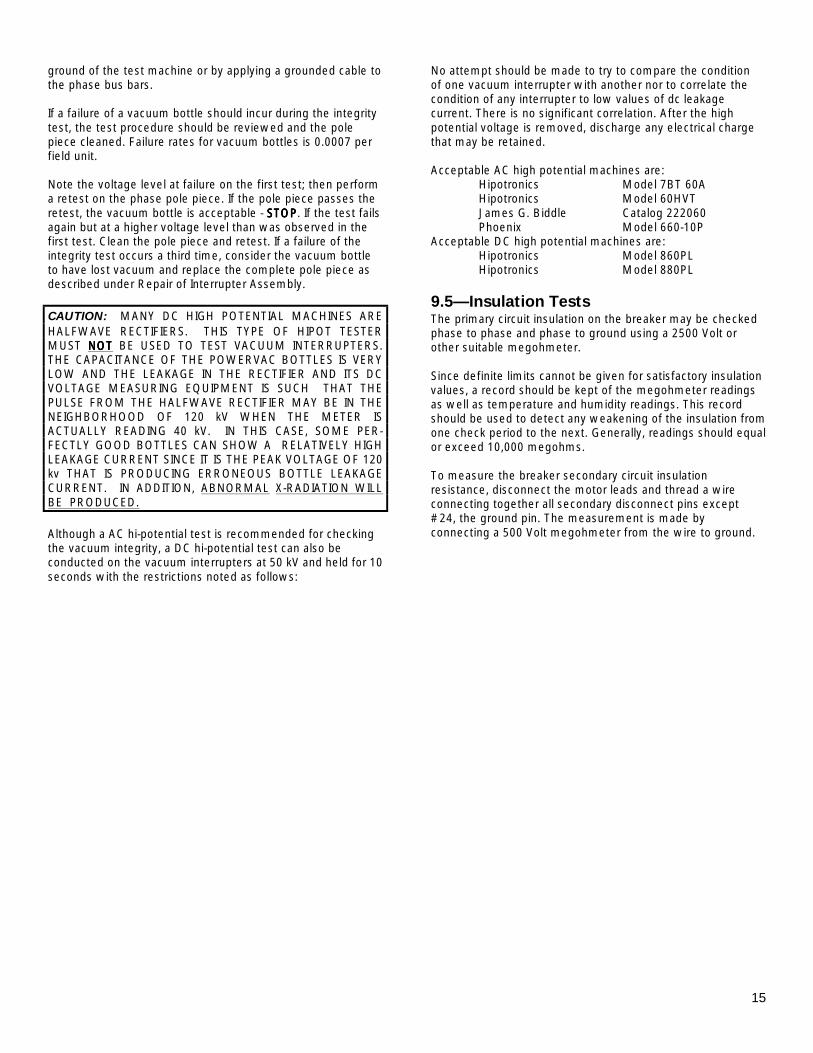
ground of the test machine or by applying a grounded cable to the phase bus bars. If a failure of a vacuum bottle should incur during the integrity test, the test procedure should be reviewed and the pole piece cleaned. Failure rates for vacuum bottles is 0.0007 per field unit. Note the voltage level at failure on the first test; then perform a retest on the phase pole piece. If the pole piece passes the retest, the vacuum bottle is acceptable - STOPSTOPSTOPSTOP. If the test fails again but at a higher voltage level than was observed in the first test. Clean the pole piece and retest. If a failure of the integrity test occurs a third time, consider the vacuum bottle to have lost vacuum and replace the complete pole piece as described under Repair of Interrupter Assembly. CAUTION: MANY DC HIGH POTENTIAL MACHINES ARE HALFWAVE RECTIFIERS. THIS TYPE OF HIPOT TESTER MUST NOTNOTNOTNOT BE USED TO TEST VACUUM INTERRUPTERS. THE CAPACITANCE OF THE POWERVAC BOTTLES IS VERY LOW AND THE LEAKAGE IN THE RECTIFIER AND ITS DC VOLTAGE MEASURING EQUIPMENT IS SUCH THAT THE PULSE FROM THE HALFWAVE RECTIFIER MAY BE IN THE NEIGHBORHOOD OF 120 kV WHEN THE METER IS ACTUALLY READING 40 kV. IN THIS CASE, SOME PER- FECTLY GOOD BOTTLES CAN SHOW A RELATIVELY HIGH LEAKAGE CURRENT SINCE IT IS THE PEAK VOLTAGE OF 120 kv THAT IS PRODUCING ERRONEOUS BOTTLE LEAKAGE CURRENT. IN ADDITION, ABNORMAL X-RADIATION WILL BE PRODUCED. Although a AC hi-potential test is recommended for checking the vacuum integrity, a DC hi-potential test can also be conducted on the vacuum interrupters at 50 kV and held for 10 seconds with the restrictions noted as follows:
No attempt should be made to try to compare the condition of one vacuum interrupter with another nor to correlate the condition of any interrupter to low values of dc leakage current. There is no significant correlation. After the high potential voltage is removed, discharge any electrical charge that may be retained. Acceptable AC high potential machines are: Hipotronics Model 7BT 60A Hipotronics Model 60HVT James G. Biddle Catalog 222060 Phoenix Model 660-10P Acceptable DC high potential machines are: Hipotronics Model 860PL Hipotronics Model 880PL
9.5—Insulation Tests The primary circuit insulation on the breaker may be checked phase to phase and phase to ground using a 2500 Volt or other suitable megohmeter. Since definite limits cannot be given for satisfactory insulation values, a record should be kept of the megohmeter readings as well as temperature and humidity readings. This record should be used to detect any weakening of the insulation from one check period to the next. Generally, readings should equal or exceed 10,000 megohms. To measure the breaker secondary circuit insulation resistance, disconnect the motor leads and thread a wire connecting together all secondary disconnect pins except #24, the ground pin. The measurement is made by connecting a 500 Volt megohmeter from the wire to ground.
16
SECTION 10—Checking and Installing Breakers
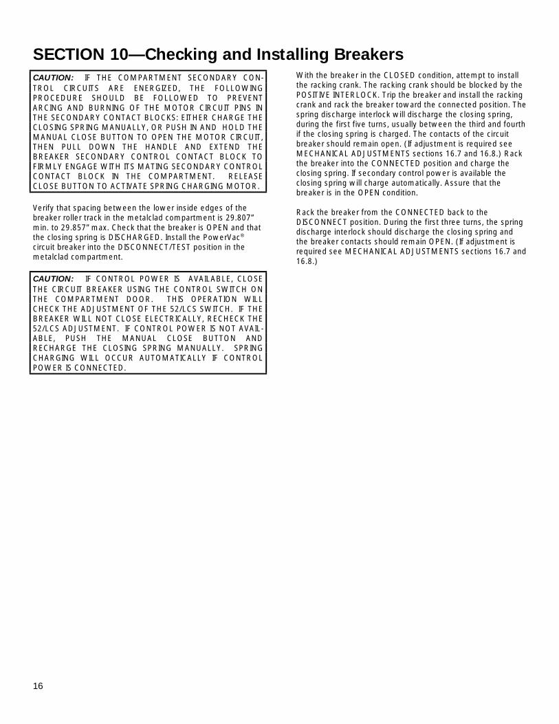
CAUTION: IF THE COMPARTMENT SECONDARY CON- TROL CIRCUITS ARE ENERGIZED, THE FOLLOWING PROCEDURE SHOULD BE FOLLOWED TO PREVENT ARCING AND BURNING OF THE MOTOR CIRCUIT PINS IN THE SECONDARY CONTACT BLOCKS: EITHER CHARGE THE CLOSING SPRING MANUALLY, OR PUSH IN AND HOLD THE MANUAL CLOSE BUTTON TO OPEN THE MOTOR CIRCUIT, THEN PULL DOWN THE HANDLE AND EXTEND THE BREAKER SECONDARY CONTROL CONTACT BLOCK TO FIRMLY ENGAGE WITH ITS MATING SECONDARY CONTROL CONTACT BLOCK IN THE COMPARTMENT. RELEASE CLOSE BUTTON TO ACTIVATE SPRING CHARGING MOTOR. Verify that spacing between the lower inside edges of the breaker roller track in the metalclad compartment is 29.807” min. to 29.857” max. Check that the breaker is OPEN and that the closing spring is DISCHARGED. Install the PowerVac® circuit breaker into the DISCONNECT/TEST position in the metalclad compartment. CAUTION: IF CONTROL POWER IS AVAILABLE, CLOSE THE CIRCUIT BREAKER USING THE CONTROL SWITCH ON THE COMPARTMENT DOOR. THIS OPERATION WILL CHECK THE ADJUSTMENT OF THE 52/LCS SWITCH. IF THE BREAKER WILL NOT CLOSE ELECTRICALLY, RECHECK THE 52/LCS ADJUSTMENT. IF CONTROL POWER IS NOT AVAIL-ABLE, PUSH THE MANUAL CLOSE BUTTON AND RECHARGE THE CLOSING SPRING MANUALLY. SPRING CHARGING WILL OCCUR AUTOMATICALLY IF CONTROL POWER IS CONNECTED.
With the breaker in the CLOSED condition, attempt to install the racking crank. The racking crank should be blocked by the POSITIVE INTERLOCK. Trip the breaker and install the racking crank and rack the breaker toward the connected position. The spring discharge interlock will discharge the closing spring, during the first five turns, usually between the third and fourth if the closing spring is charged. The contacts of the circuit breaker should remain open. (If adjustment is required see MECHANICAL ADJUSTMENTS sections 16.7 and 16.8.) Rack the breaker into the CONNECTED position and charge the closing spring. If secondary control power is available the closing spring will charge automatically. Assure that the breaker is in the OPEN condition. Rack the breaker from the CONNECTED back to the DISCONNECT position. During the first three turns, the spring discharge interlock should discharge the closing spring and the breaker contacts should remain OPEN. (If adjustment is required see MECHANICAL ADJUSTMENTS sections 16.7 and 16.8.)
17
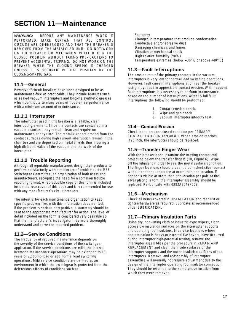
SECTION 11—Maintenance WARNING: BEFORE ANY MAINTENANCE WORK IS PERFORMED, MAKE CERTAIN THAT ALL CONTROL CIRCUITS ARE DE-ENERGIZED AND THAT THE BREAKER IS REMOVED FROM THE METALCLAD UNIT. DO NOT WORK ON THE BREAKER OR MECHANISM WHILE IT IS IN THE CLOSED POSITION WITHOUT TAKING PRE- CAUTIONS TO PREVENT ACCIDENTAL TRIPPING. DO NOT WORK ON THE BREAKER WHILE THE CLOSING SPRING IS CHARGED UNLESS IT IS SECURED IN THAT POSITION BY THE CLOSING-SPRING GAG.
11.1—General PowerVac® circuit breakers have been designed to be as maintenance-free as practicable. They include features such as sealed vacuum interrupters and long-life synthetic greases which contribute to many years of trouble-free performance with a minimum amount of maintenance.
11.1.1 Interrupter The interrupter used in this breaker is a reliable, clean interrupting element. Since the contacts are contained in a vacuum chamber, they remain clean and require no maintenance at any time. The metallic vapors eroded from the contact surfaces during high current interruption remain in the chamber and are deposited on metal shields thus insuring a high dielectric value of the vacuum and the walls of the interrupter.
11.1.2 Trouble Reporting Although all reputable manufacturers design their products to perform satisfactorily with a minimum of problems, the IEEE Switchgear Committee, an organization of both users and manufacturers, recognize the need for a common trouble reporting format. A reproducible copy of this form is included inside the rear cover of this book and is recommended for use with any manufacturer’s circuit breakers. The intent is for each maintenance organization to keep specific problem files with this information documented. If the problem is serious or repetitive, a summary should be sent to the appropriate manufacturer for action. The level of detail included on the form is considered very desirable so that the manufacturer’s investigator may more thoroughly understand and solve the reported problem.
11.2—Service Conditions The frequency of required maintenance depends on the severity of the service conditions of the switchgear application. If the service conditions are mild, the interval between maintenance operations may be extended to 10 years or 2,500 no load or 200 normal load switching operations. Mild service conditions are defined as an environment in which the switchgear is protected from the deleterious effects of conditions such as:
Salt spray Changes in temperature that produce condensation Conductive and/or abrasive dust Damaging chemicals and fumes Vibration or mechanical shock High relative humidity (90%) Temperature extremes (below –30° C or above +40° C)
11.3—Fault Interruptions The erosion rate of the primary contacts in the vacuum interrupters is very low for normal load switching operations. However, fault current interruptions at or near the breaker rating may result in appreciable contact erosion. With frequent fault interruptions it is necessary to perform maintenance based on the number of interruptions. After 15 full fault interruptions the following should be performed: 1. Contact erosion check. 2. Wipe and gap check 3. Vacuum interrupter integrity test.
11.4—Contact Erosion Check in the breaker-closed condition per PRIMARY CONTACT EROSION section 8.1. When erosion reaches .125 inch, the interrupter should be replaced.
11.5—Transfer Finger Wear With the breaker open, examine the moving contact rod projecting below the transfer fingers (10, Figure 6). Wipe off the lubricant in order to see the metal surface condition. The finger locations should present a burnished silver contact without copper appearance at more than one location. If copper is visible at more than one location per pole or the silver plating is torn, the interrupter assembly should be replaced. Re-lubricate with 0282A2048P009.
11.6—Mechanism Check all items covered in INSTALLATION and readjust or tighten hardware as required. Lubricate as recommended under LUBRICATION.
11.7—Primary Insulation Parts Using dry, non-linting cloth or industrial-type wipers, clean accessible insulation surfaces on the interrupter supports and operating rod insulators. In service locations where contamination is heavy or external flashovers, have occurred during interrupter high-potential testing, remove the interrupter assemblies per the procedure in REPAIR AND REPLACEMENT and clean the inside surfaces of the interrupter supports and the outer insulation surfaces of the interrupters. Removal and reassembly of interrupter assemblies will normally not require adjustment due to the design of the interrupter operating rod insulator connection. They should be returned to the same phase location from which they were removed.
18
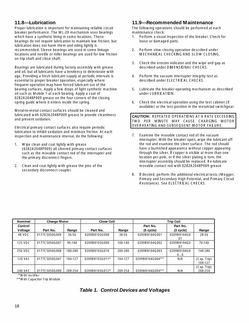
11.8—Lubrication Proper lubrication is important for maintaining reliable circuit breaker performance. The ML-20 mechanism uses bearings which have a synthetic lining in some locations. These bearings do not require lubrication to maintain low friction, but lubrication does not harm them and oiling lightly is recommended. Sleeve bearings are used in some linkage locations and needle or roller bearings are used for low friction on trip shaft and close shaft. Bearings are lubricated during factory assembly with grease and oil, but all lubricants have a tendency to deteriorate with age. Providing a fresh lubricant supply at periodic intervals is essential to proper breaker operation, especially where frequent operation may have forced lubricant out of the bearing surfaces. Apply a few drops of light synthetic machine oil such as Mobile 1 at each bearing. Apply a coat of 0282A2048P009 grease on the four corners of the closing spring guide where it enters inside the spring. Metal-to-metal contact surfaces should be cleaned and lubricated with 0282A2048P009 grease to provide cleanliness and prevent oxidation. Electrical primary contact surfaces also require periodic lubrication to inhibit oxidation and minimize friction. At each inspection and maintenance interval, do the following: 1. Wipe clean and coat lightly with grease
(0282A2048P009) all silvered primary contact surfaces such as the movable contact rod of the interrupter and the primary disconnect fingers.
2. Clean and coat lightly with grease the pins of the
secondary disconnect coupler.
11.9—Recommended Maintenance The following operations should be performed at each maintenance check: 1. Perform a visual inspection of the breaker. Check for
loose or damaged parts. 2. Perform slow closing operation described under
MECHANICAL CHECKING AND SLOW CLOSING. 3. Check the erosion indicator and the wipe and gap as
described under DIMENSIONAL CHECKS. 4. Perform the vacuum interrupter integrity test as
described under ELECTRICAL CHECKS. 5. Lubricate the breaker operating mechanism as described
under LUBRICATION. 6. Check the electrical operation using the test cabinet (if
available) or the test position in the metalclad switchgear.
CAUTION: REPEATED OPERATIONS AT A RATE EXCEEDING TWO PER MINUTE MAY CAUSE CHARGING MOTOR OVERHEATING AND SUBSEQUENT MOTOR FAILURE. 7. Examine the movable contact rod of the vacuum
interrupter. With the breaker open, wipe the lubricant off the rod and examine the silver surface. The rod should have a burnished appearance without copper appearing through the silver. If copper is visible at more than one location per pole, or if the silver plating is torn, the interrupter assembly should be replaced. Re-lubricate movable contact rod with 0282A2048P009 grease
8. If desired, perform the additional electrical tests (Megger,
Primary and Secondary High Potential, and Primary Circuit Resistance). See ELECTRICAL CHECKS.
Nominal Charge Motor Close Coil Trip Coil Control Voltage
Part No.
Range
Part No.
Range
Part No. (5 cycle)
Part No. (3 cycle)
Range
48 VDC 0177C5050G009 36-56 0209B8103G008 38-56 0209B8104G001 0209B8104G001
28-56
125 VDC 0177C5050G007 90-140 0209B8103G009 100-140 0209B8104G002 0209B8104G007
70-140
250 VDC 0177C5050G008 180-280 0209B8103G010 200-280 0209B8104G003 0209B8104G00…6
140-280
120 VAC 0177C5050G047 104-127 0209B8103G011* 104-127 0209B8104G004** N/A (Cap. Trip) 104-127
240 VAC
0177C5050G008
208-254
0209B8103G012*
209-254
0209B8104G004**
N/A
(Cap. Trip) 208-254
*With rectifier **With Capacitor Trip Module
Table 1. Control Devices and Voltages
19
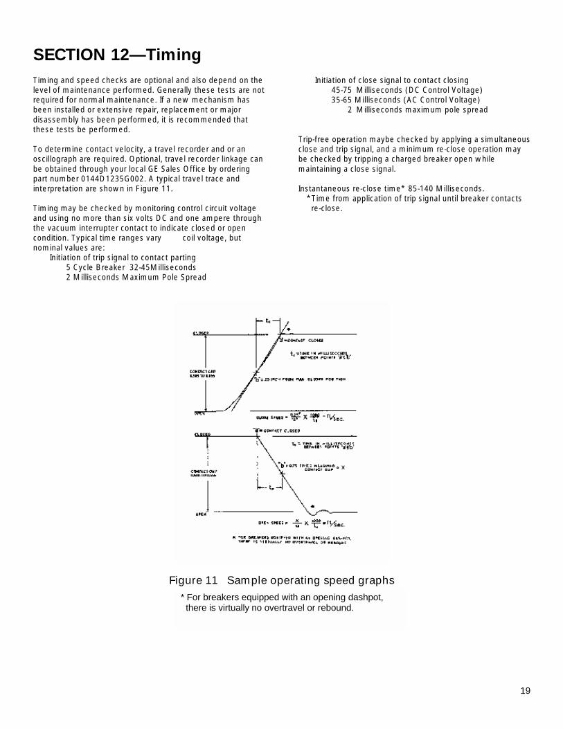
SECTION 12—Timing Timing and speed checks are optional and also depend on the level of maintenance performed. Generally these tests are not required for normal maintenance. If a new mechanism has been installed or extensive repair, replacement or major disassembly has been performed, it is recommended that these tests be performed. To determine contact velocity, a travel recorder and or an oscillograph are required. Optional, travel recorder linkage can be obtained through your local GE Sales Office by ordering part number 0144D1235G002. A typical travel trace and interpretation are shown in Figure 11. Timing may be checked by monitoring control circuit voltage and using no more than six volts DC and one ampere through the vacuum interrupter contact to indicate closed or open condition. Typical time ranges vary with coil voltage, but nominal values are: Initiation of trip signal to contact parting 5 Cycle Breaker 32-45Milliseconds 2 Milliseconds Maximum Pole Spread
Initiation of close signal to contact closing 45-75 Milliseconds (DC Control Voltage) 35-65 Milliseconds (AC Control Voltage) 2 Milliseconds maximum pole spread Trip-free operation maybe checked by applying a simultaneous close and trip signal, and a minimum re-close operation may be checked by tripping a charged breaker open while maintaining a close signal. Instantaneous re-close time* 85-140 Milliseconds.
*Time from application of trip signal until breaker contacts re-close.
Figure 11 Sample operating speed graphs
* For breakers equipped with an opening dashpot, there is virtually no overtravel or rebound.
20
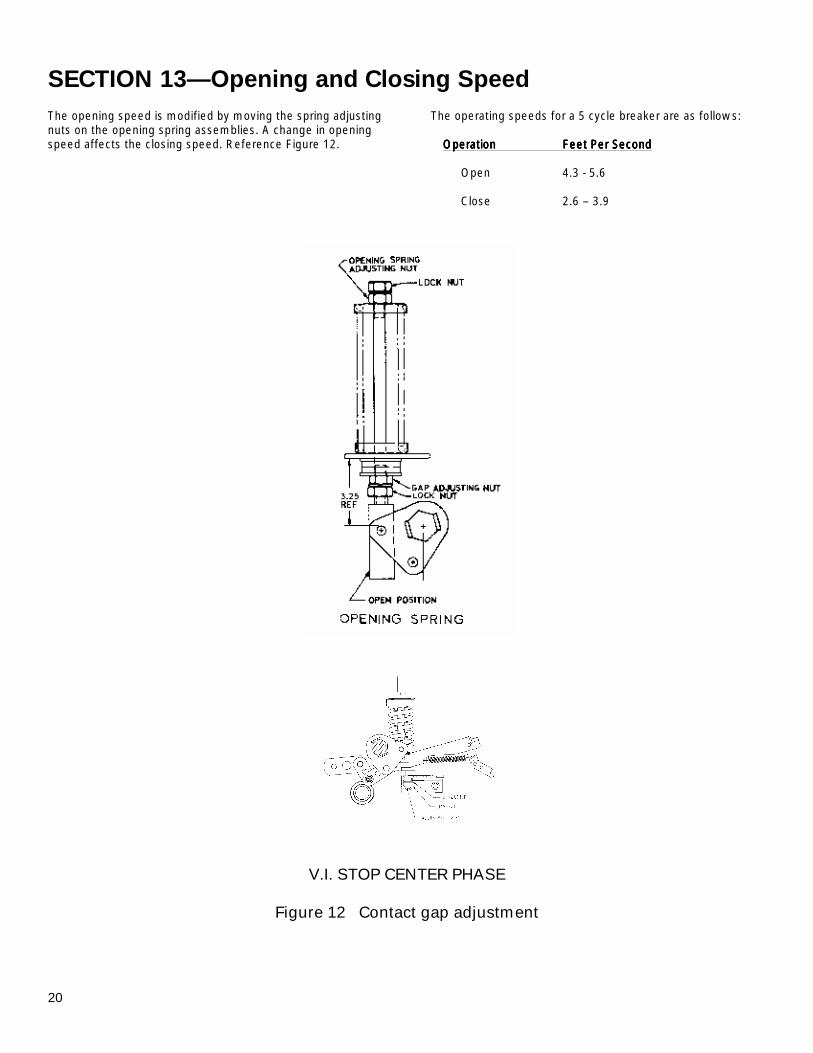
SECTION 13—Opening and Closing Speed The opening speed is modified by moving the spring adjusting nuts on the opening spring assemblies. A change in opening speed affects the closing speed. Reference Figure 12.
The operating speeds for a 5 cycle breaker are as follows: OperationOperationOperationOperation Feet Per SecondFeet Per SecondFeet Per SecondFeet Per Second Open 4.3 - 5.6 Close 2.6 – 3.9
V.I. STOP CENTER PHASE
Figure 12 Contact gap adjustment
21
SECTION 14—Repair and Replacement
14.1—General The following information covers in detail the proper method of removing various parts of the breaker in order to make any necessary repairs. This section includes only those repairs that can be made at the installation site on parts of the breaker that are most subject to damage. Important: Upon completion of any kind of repair work, all interrupter and mechanism adjustments must be checked. Refer as needed to sections on mechanical and electrical adjustments.
14.2—Replacement of Interrupter Assemblies
Interrupters are supplied in complete interrupter assemblies which include the vacuum interrupter mounted in the interrupter support, the primary studs, and disconnect fingers.
CAUTION: DO NOT ATTEMPT TO REMOVE OR REINSERT THE VACUUM INTERRUPTER IN THE INTERRUPTER SUPPORT ASSEMBLY. SPECIAL TOOLS AVAILABLE AT THE FACTORY ARE REQUIRED. 1. Close the breaker and remove the coupling clamp, and
clamp screws(8, 9, Figure 6). Hold hex projection (6, Figure 8) at the bottom of the operating rod insulator with a 1 inch wrench and loosen the adjacent lock nut with a 3/4 inch wrench. Screw down the lock nut and the operating rod insulator until clear of interrupter rod. Remove the four bolts holding the pole assembly to the mechanism and remove the old pole assembly.
2. Set the new pole assembly in place and install the four
mounting bolts. Set the pole assembly so that the distance between the primary studs and the studs on the adjacent pole is ten (10) inches center line to center line.
3. Screw the operating rod insulator up to mate with the
base of the interrupter rod. Install coupling clamp. Tighten coupling clamp capscrews, then loosen them 1-2 turns.
a. With continuity indicator across the contacts, back off
the operating rod until the contacts separate, (continuity indicator off).
b. Advance operating rod until contacts touch,
(continuity indicator on). c. Advance operating rod two and one-half (2-1/2)
additional turns. d. Tighten lock nut to 40-50 pounds/foot and the
coupling clamp capscrews to 8-10 pounds/foot.
e. Check contact wipe - must be 0.160 – 0.185 inch (set
all three phases before measuring). It is not necessary that all three poles have the same wipe measurement as long as all three poles fall within the specified limits.
f. Check contact gap - must be 0.595 – 0.655 inch.
Adjust if needed per CONTACT GAP ADJUSTMENT in MECHANICAL ADJUSTMENT section.
4. If a new interrupter assembly is installed, check and
adjust the wipe indicator (2, Figure 6) by bending the reference arm (11, Figure 6) to line up with erosion disk.
5. Perform the VACUUM INTERRUPTER INTEGRITY TEST
as described in ELECTRICAL CHECKS section. WARNING: PRIMARY DISCONNECT WIPE CAN ONLY BE CHECKED WHEN THE SWITCHGEAR IS DE-ENERGIZED.
14.3—Primary Disconnect Fingers The primary disconnect finger assemblies can be removed by removing two roll pins which hold them in place on the primary studs. Finger contact surfaces should be coated with 0282A2048P009 lubricant.
14.4—Mechanism Pin Retaining Rings - These rings are widely used in the ML-20 mechanism to retain pins. They can be installed and removed with a pair of standard pliers. Reuse is not recommended. To remove, slowly squeeze the ears while pulling. To install, position in the pin groove and squeeze the installation ears closed leaving no more than 1/16 inch gap between ears. Retaining rings can be obtained from your local GE Sales Office by ordering part number 0282A2015G001.
14.5—Control Switches Control switches may be removed from their mounting brackets by disconnecting the wires and removing the mounting hardware. When replacing the switches, check that the correct type normally open or normally closed, is used. Reinstall, wire, and adjust per DIMENSIONAL CHECKS - CONTROL SWITCH ADJUSTMENT.
14.6—Trip Coil Replacement TOOLS REQUIRED 5/16” Allen wrench Needle nose pliers 7/16” Socket wrench 7/16” Box/combination wrench 1/4” Square drive ratchet 1/4” Square 3” extension Loctite #271 or equivalent
22
Perform the operation in the following sequence: 1. Charge closing spring and install gag plate. 2. Depress the close and then the trip buttons. 3. Pump the manual close handle 3 - 4 times. 4. With the 5/16” Allen wrench, remove the pivot bolt (10, Figure 21) on the closing spring (1, Figure 21). 5. Remove the closing spring. 6. Disconnect the trip linkage tension spring. 7. Loosen the interlock bracket (11, Figure 21). 8. Remove the 4 bolts from the coil bracket leaving the two
bolts nearest the front of the breaker in place in the mechanism frame.
9. Cut coil leads and remove the coil and armature. To install the new coil, reverse the above procedure and connect leads with insulated butt connectors. See TRIP COIL PLUNGER in MECHANICAL ADJUSTMENTS section for setting the stroke of the armature. Apply Loctite to the threads of the pivot bolt (10, Figure 21) when it is replaced. Charge the breaker and electrically close and trip it to make certain it has been reassembled correctly.
14.7—Closing Coil Replacement Disconnect the close linkage tension spring then remove the retaining ring from the close linkage pivot pin (17, Figure 21) and disconnect the linkage. Remove the closing coil and housing (6, Figure 21). Cut the leads to the closing coil and remove the coil. Reassemble the coil and housing with armature and butt-splice the new coil into the wiring harness. Reassemble linkage and spring. Readjust the closing coil armature travel in accordance with instructions in MECHANICAL ADJUSTMENTS section under CLOSE COIL PLUNGER.
14.8—Auxiliary Switch Replacement With the breaker open and the closing spring discharged, remove retaining clip from auxiliary switch shaft. Observe and make of the
direction of the index mark on the end of the shaft and the position of the operating link in relation to the stop screw. Remove mounting hardware securing auxiliary switch to mechanism plate. Slide auxiliary switch and shaft out of operating link. Before removing any wires from switch terminals, make sure they are properly tagged with switch terminal numbers to assure proper placement on new switch. Remove wires. To install new switch, attach leads then install switch. Install switch shaft in operating link with index mark aligned as noted above. Reverse above procedure to complete installation.
14.9—Motor Replacement With the breaker open and the closing spring discharged, remove auxiliary switch as described above but do not disconnect leads. Move switch toward side of mechanism far enough to clear motor and tie there temporarily. Disconnect motor leads. Remove the long bolt and spacer securing the motor to the mechanism mid-plate. Remove the two socket head cap screws securing the motor to the mechanism top plate using a 5/16” Allen socket and a 24” extension. Disengage the motor output shaft from the charge linkage arms and withdraw motor. To install the new motor, reverse the above procedure.
14.10—“Y” Relay Replacement Before removing the “Y” relay, make sure all leads are marked with terminal locations. Next, disconnect all leads and remove the two fasteners securing the “Y” relay’s shock absorbing mounting bracket to the mechanism rear plate. Withdraw relay and bracket. Remove fasteners securing relay to mounting bracket. Reverse the above procedure to install new relay.
23
SECTION 15—Renewal Parts It is recommended that sufficient renewal parts be carried in stock to enable the prompt replacement of any worn, broken or damaged parts. A stock of such parts minimizes service interruptions caused by breakdowns, and saves time and expense. When continuous operation is a primary consideration, more renewal parts should be carried, the amount depending upon the severity of the service and the time required to secure replacements.
Renewal parts which are furnished may not be identical to the original parts, but they will be interchangeable.
Renewal Part numbers are available from your local GE Sales office.
15.1—Ordering Instructions 1. Always specify the complete nameplate data of both the
breaker and mechanism. 2. Specify the quantity, catalog number (if listed), reference
number (if listed), and description of each part ordered, and the parts bulletin number.
3. Standard hardware, such as screws, bolts, nuts, washer,
etc., should be purchased locally.
SECTION 16—Mechanical Adjustments
16.1—General The ML-20 Mechanism has been designed for extended intervals between maintenance. In most cases only the wipe and gap adjustments will require re-setting throughout the life of the circuit breaker.
16.2—Wipe Adjustment Wipe is the additional compression of a preloaded spring, used to apply force to the vacuum interrupter contacts and to provide opening kick-off force. The contact wipe adjustment should always be made before making the contact gap adjustment. ML-20 The wipe measurement is made with the breaker closed and the closing spring gagged. Measure with a feeler gauge the distance between the bellville washer and the trunion between the bell cranks arms. Adjustment is not required if wipe is more than 0.100 inch. After adjustment the wipe should be 0.160 – 0.185 inch. To adjust the primary contact wipe, close the breaker and proceed as follows:
1. Loosen, but do not remove, the two capscrews (9, Figure 8) holding the interrupter clamp.
2. Check that the interrupter clamp is loose. A light pry at the clamp half-junction may be required to loosen the wedging action of the clamp.
3. Hold the hexagon projection (6, Figure 6) at the bottom of the operating rod insulator (1 inch wrench) and loosen the adjacent locknut (3/4 inch wrench). (Refer to 4, Figure 6). Adjust by rotating the operating rod insulator. The thread is 1/2-13 and each turn will give about 0.076 inch change in primary wipe. Screw the operating rod insulator toward the interrupter to increase wipe.
4. After setting the contact wipe on each phase, torque the operating rod locknut (4, Figure 6) to 40-50 pounds/foot while holding the hex projection (6) to prevent the operating rod insulator (7) from turning. Tighten the clamp screws (9) to 8-10 pounds/foot and trip the breaker open. This procedure prevents accidental twisting of the interrupter’s operating rod by loading the contacts with
the wipe springs and forcing relative rotation to occur at the clamp interface.
After adjustment, remeasure the wipe dimensions. If the wipe settings are within the required limits, there is an adequate contact closing relationship between the poles.
16.3—Contact Gap Adjustment The gap adjustment refers to the separation, or gap, between the primary contacts within the vacuum interrupter. Before attempting to measure or set the gap adjustment, verify that the wipe settings are within acceptable limits. Any change of the wipe settings will affect the gap settings.
1. Adjust the center phases first. The contact gap must be 0.595 – 0.655. The adjustment of the outer phases affects the center phase measurement. With the breaker in the open position and the closing spring discharged, locate the gap adjusting nuts on the opening spring rods connected to the outer phase bell cranks (Figure 12). Loosen the jam nut on both rods. Back off the adjusting bolt on the center phase VI stop (Figure 12).
2. Advance or retard the adjusting nuts depending on which way you want to change the gap. Move both nuts the same amount.
3. Lock the jam nuts after setting the adjusting nuts. Operate the breaker a few times and remeasure the gap following the procedure described in DIMENSIONAL CHECKS, item 3.
4. Readjust the center phase VI stop (Figure 12). Set adjusting screw for no clearance between stop and wipe spring rod striker with the breaker open.
After adjustment of the left and right phase, remeasure the center phase. The center phase should not exceed 0.655 inch. If it does then readjust the left and right phases.
16.4—Trip Coil Plunger To adjust trip coil plunger gap (Figure 9), lift locktab away from adjusting nut. Turn adjusting nut until trip pin makes contact with trip arm while maintaining dimension T. Bend locktab to secure adjusting nut.
24
Reference DIMENSIONAL CHECKS for breaker position and spring status.
16.5—Close Coil Plunger To adjust the close coil plunger gap, Figure 8, lift locktab away from adjusting nut. Turn adjusting nut until close latch actuator makes contact with close latch while maintaining the correct plunger dimension. Bend locktab to secure adjusting nut. Reference dimensional checks for required dimension and breaker position and spring status.
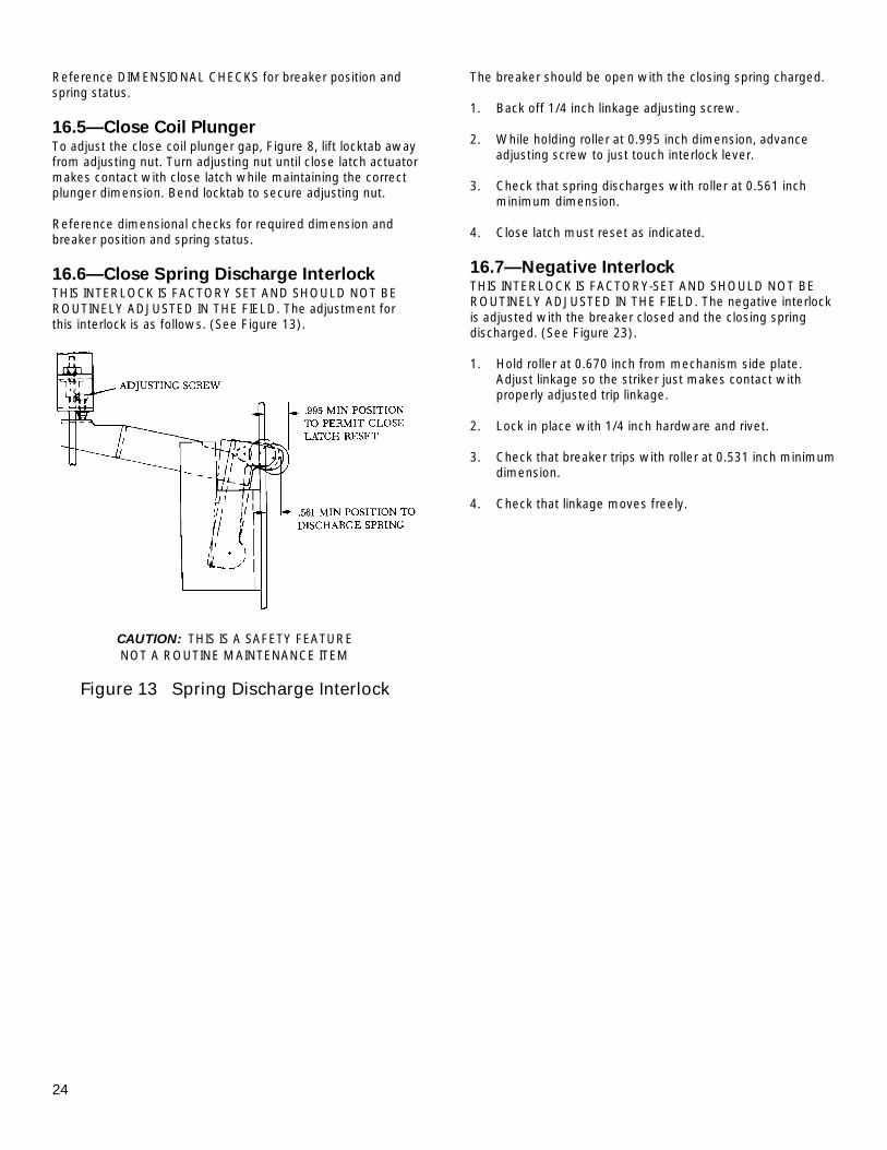
16.6—Close Spring Discharge Interlock THIS INTERLOCK IS FACTORY SET AND SHOULD NOT BE ROUTINELY ADJUSTED IN THE FIELD. The adjustment for this interlock is as follows. (See Figure 13).
CAUTION: THIS IS A SAFETY FEATURE NOT A ROUTINE MAINTENANCE ITEM
Figure 13 Spring Discharge Interlock
The breaker should be open with the closing spring charged. 1. Back off 1/4 inch linkage adjusting screw. 2. While holding roller at 0.995 inch dimension, advance
adjusting screw to just touch interlock lever. 3. Check that spring discharges with roller at 0.561 inch
minimum dimension. 4. Close latch must reset as indicated.
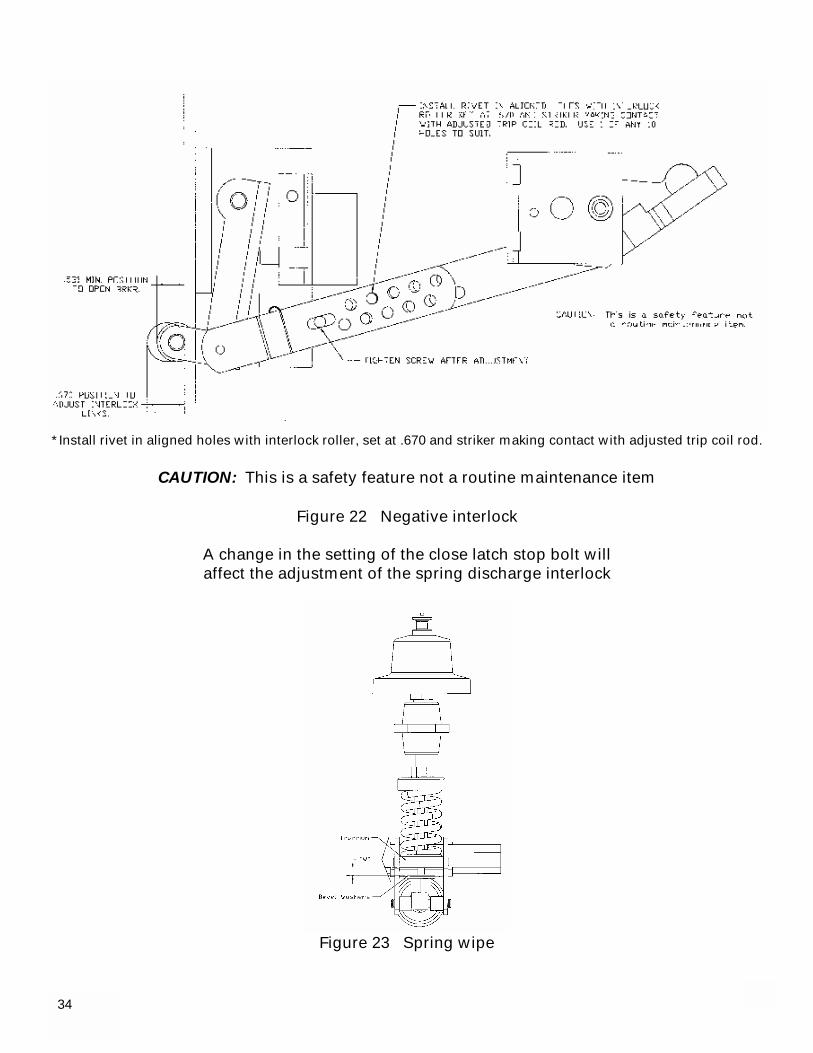
16.7—Negative Interlock THIS INTERLOCK IS FACTORY-SET AND SHOULD NOT BE ROUTINELY ADJUSTED IN THE FIELD. The negative interlock is adjusted with the breaker closed and the closing spring discharged. (See Figure 23). 1. Hold roller at 0.670 inch from mechanism side plate.
Adjust linkage so the striker just makes contact with properly adjusted trip linkage.
2. Lock in place with 1/4 inch hardware and rivet. 3. Check that breaker trips with roller at 0.531 inch minimum
dimension. 4. Check that linkage moves freely.
25
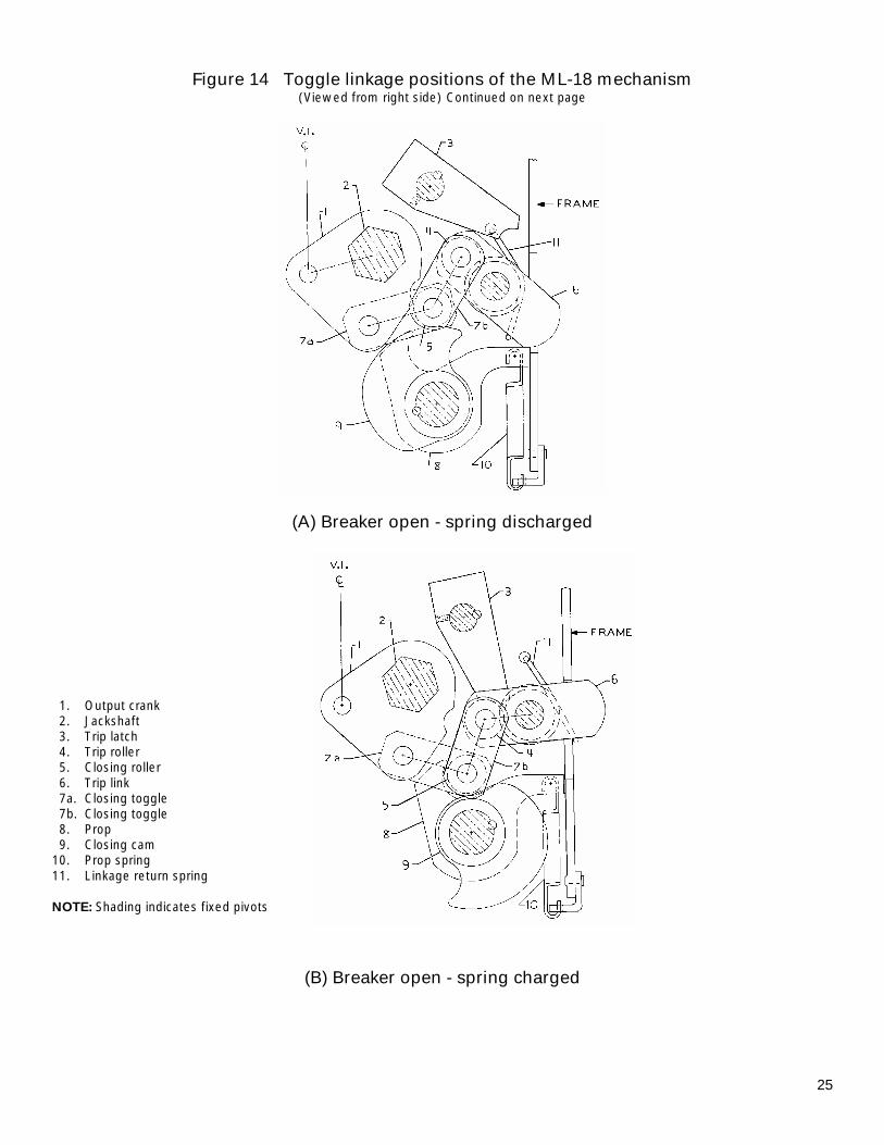
Figure 14 Toggle linkage positions of the ML-18 mechanism (Viewed from right side) Continued on next page
(A) Breaker open - spring discharged
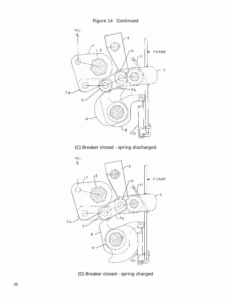
1. Output crank 2. Jackshaft 3. Trip latch 4. Trip roller 5. Closing roller 6. Trip link 7a. Closing toggle 7b. Closing toggle 8. Prop 9. Closing cam 10. Prop spring 11. Linkage return spring NOTE: Shading indicates fixed pivots
(B) Breaker open - spring charged
26
Figure 14 Continued
(C) Breaker closed - spring discharged
(D) Breaker closed - spring charged
27
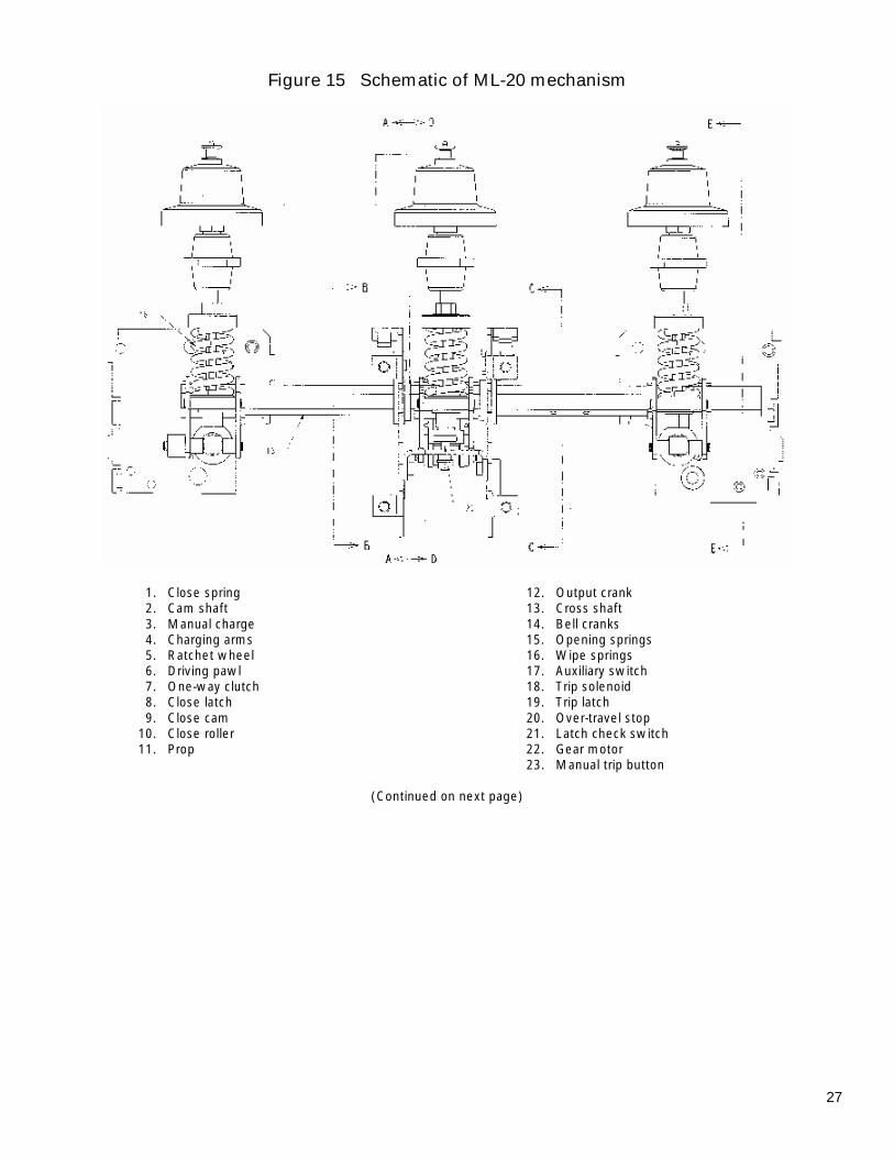
Figure 15 Schematic of ML-20 mechanism
1. Close spring 12. Output crank 2. Cam shaft 13. Cross shaft 3. Manual charge 14. Bell cranks 4. Charging arms 15. Opening springs 5. Ratchet wheel 16. Wipe springs 6. Driving pawl 17. Auxiliary switch 7. One-way clutch 18. Trip solenoid 8. Close latch 19. Trip latch 9. Close cam 20. Over-travel stop 10. Close roller 21. Latch check switch 11. Prop 22. Gear motor 23. Manual trip button
(Continued on next page)
28
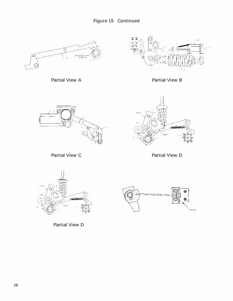
Figure 15 Continued
Partial View A Partial View B
Partial View C Partial View D
Partial View D
29
Figure 16 Typical wiring diagram for ML-20 mechanism
30
Figure 17 PowerVac breaker left-front view 1. Gag interlock angle 2. Track rollers 3. Positive interlock bar 4. Closing spring discharge roller 5. Negative interlock roller 6. Rating interference plate 7. Front cover 8. Racking engagement lever 9. Secondary coupler
Figure 18 PowerVac breaker right-rear view
7
8
2
4
9 6
8
7
8
2
3 5
1
31
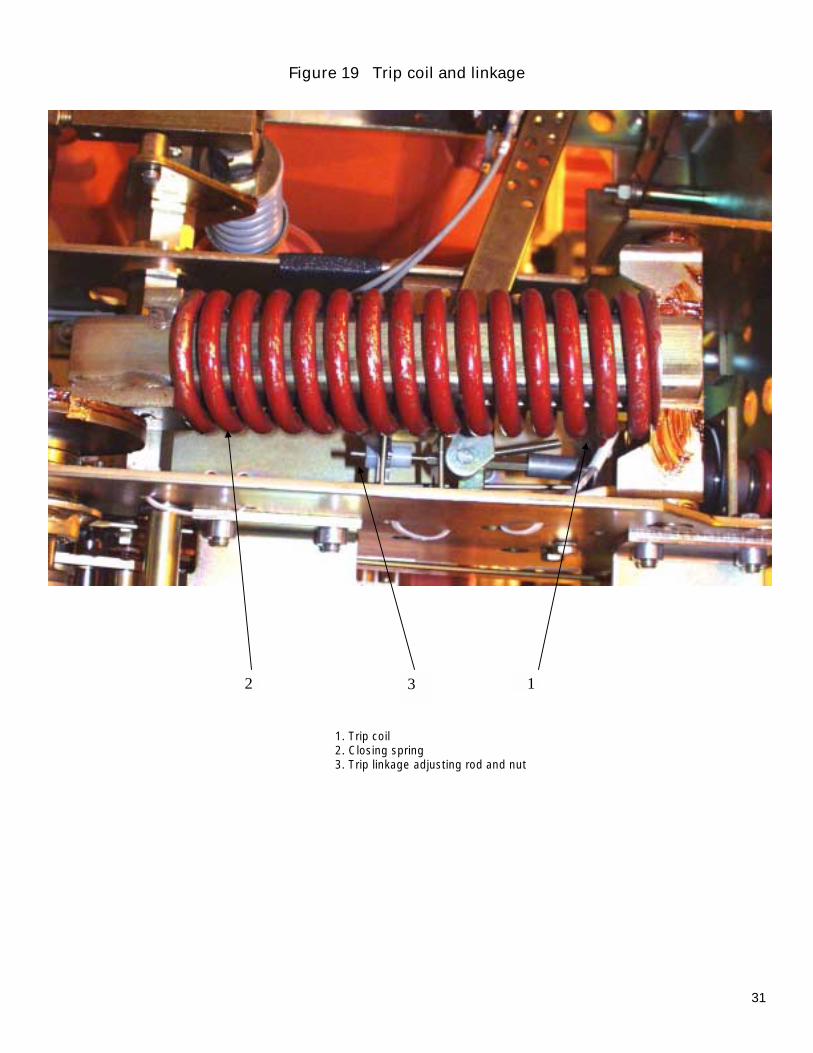
Figure 19 Trip coil and linkage
1. Trip coil 2. Closing spring 3. Trip linkage adjusting rod and nut
3 1 2
32
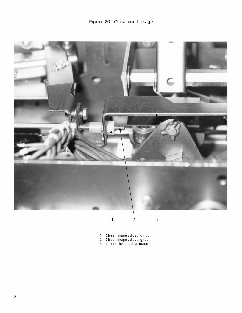
Figure 20 Close coil linkage
1. Close linkage adjusting nut 2. Close linkage adjusting rod 3. Link to close latch actuator
1 2 3

33
Figure 21 Bottom view of ML-18 mechanism
5
1. Closing spring 10. Pivot bolt 2. Opening springs 11. Interlock bracket 3. Auxiliary switch 12. SM/LS motor control switch 4. Spring charging motor 13. LCS latch checking switch 5. Trip coil 14. CL/MS close latch monitor switch 6. Close coil 15. Stationary auxiliary switch operator 7. Ratchet wheel 16. Close latch adjustment screw 8. Closing cam on -0, -1 & -2 breakers only 9. 52Y relay 17. Close linkage pivot
3 4 6
1
11
10
9
2
12
8 16 13
2
17 7
15
5
*Install rivet in aligned holes with interlock roller, set at .670 and striker making contact with adjusted trip coil rod.
CAUTION: This is a safety feature not a routine maintenance item
Figure 22 Negative interlock
A change in the setting of the close latch stop bolt will affect the adjustment of the spring discharge interlock
Figure 23 Spring wipe
34
3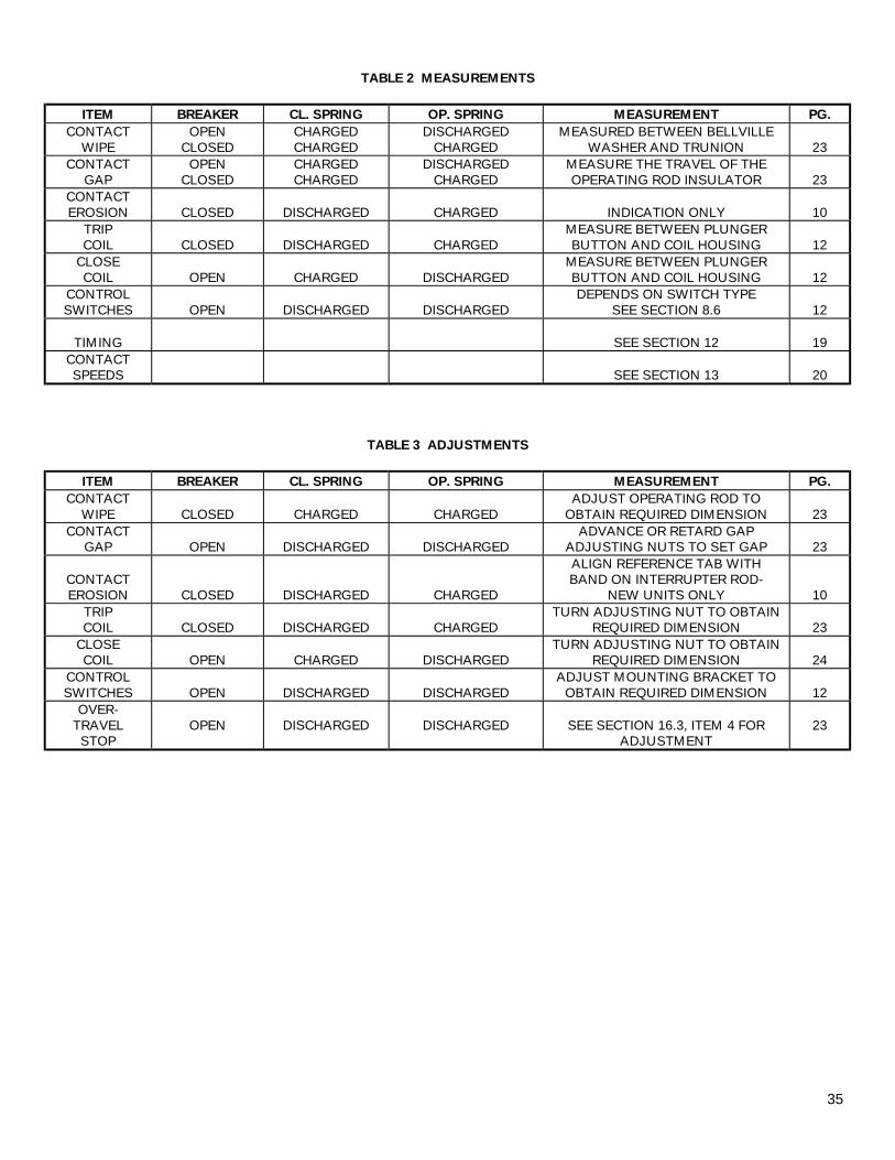
35
TABLE 2 MEASUREMENTS
ITEM BREAKER CL. SPRING OP. SPRING MEASUREMENT PG. CONTACT
WIPE OPEN
CLOSED CHARGED CHARGED
DISCHARGED CHARGED
MEASURED BETWEEN BELLVILLE WASHER AND TRUNION
23
CONTACT GAP
OPEN CLOSED
CHARGED CHARGED
DISCHARGED CHARGED
MEASURE THE TRAVEL OF THE OPERATING ROD INSULATOR
23
CONTACT EROSION
CLOSED
DISCHARGED
CHARGED
INDICATION ONLY
10
TRIP COIL
CLOSED
DISCHARGED
CHARGED
MEASURE BETWEEN PLUNGER BUTTON AND COIL HOUSING
12
CLOSE COIL
OPEN
CHARGED
DISCHARGED
MEASURE BETWEEN PLUNGER BUTTON AND COIL HOUSING
12
CONTROL SWITCHES
OPEN
DISCHARGED
DISCHARGED
DEPENDS ON SWITCH TYPE SEE SECTION 8.6
12
TIMING
SEE SECTION 12
19
CONTACT SPEEDS
SEE SECTION 13
20
TABLE 3 ADJUSTMENTS
ITEM BREAKER CL. SPRING OP. SPRING MEASUREMENT PG. CONTACT
WIPE
CLOSED
CHARGED
CHARGED ADJUST OPERATING ROD TO
OBTAIN REQUIRED DIMENSION
23 CONTACT
GAP
OPEN
DISCHARGED
DISCHARGED ADVANCE OR RETARD GAP
ADJUSTING NUTS TO SET GAP
23
CONTACT EROSION
CLOSED
DISCHARGED
CHARGED
ALIGN REFERENCE TAB WITH BAND ON INTERRUPTER ROD-
NEW UNITS ONLY
10 TRIP COIL
CLOSED
DISCHARGED
CHARGED
TURN ADJUSTING NUT TO OBTAIN REQUIRED DIMENSION
23
CLOSE COIL
OPEN
CHARGED
DISCHARGED
TURN ADJUSTING NUT TO OBTAIN REQUIRED DIMENSION
24
CONTROL SWITCHES
OPEN
DISCHARGED
DISCHARGED
ADJUST MOUNTING BRACKET TO OBTAIN REQUIRED DIMENSION
12
OVER- TRAVEL
STOP
OPEN
DISCHARGED
DISCHARGED
SEE SECTION 16.3, ITEM 4 FOR
ADJUSTMENT
23
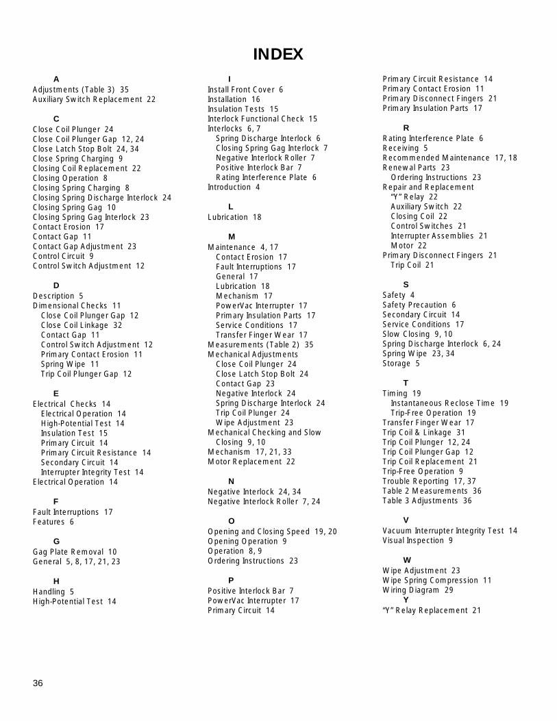
36
INDEX A Adjustments (Table 3) 35 Auxiliary Switch Replacement 22 C Close Coil Plunger 24 Close Coil Plunger Gap 12, 24 Close Latch Stop Bolt 24, 34 Close Spring Charging 9 Closing Coil Replacement 22 Closing Operation 8 Closing Spring Charging 8 Closing Spring Discharge Interlock 24 Closing Spring Gag 10 Closing Spring Gag Interlock 23 Contact Erosion 17 Contact Gap 11 Contact Gap Adjustment 23 Control Circuit 9 Control Switch Adjustment 12 D Description 5 Dimensional Checks 11 Close Coil Plunger Gap 12 Close Coil Linkage 32 Contact Gap 11 Control Switch Adjustment 12 Primary Contact Erosion 11 Spring Wipe 11 Trip Coil Plunger Gap 12 E Electrical Checks 14 Electrical Operation 14 High-Potential Test 14 Insulation Test 15 Primary Circuit 14 Primary Circuit Resistance 14 Secondary Circuit 14 Interrupter Integrity Test 14 Electrical Operation 14 F Fault Interruptions 17 Features 6 G Gag Plate Removal 10 General 5, 8, 17, 21, 23 H Handling 5 High-Potential Test 14
I Install Front Cover 6 Installation 16 Insulation Tests 15 Interlock Functional Check 15 Interlocks 6, 7 Spring Discharge Interlock 6 Closing Spring Gag Interlock 7 Negative Interlock Roller 7 Positive Interlock Bar 7 Rating Interference Plate 6 Introduction 4 L Lubrication 18 M Maintenance 4, 17 Contact Erosion 17 Fault Interruptions 17 General 17 Lubrication 18 Mechanism 17 PowerVac Interrupter 17 Primary Insulation Parts 17 Service Conditions 17 Transfer Finger Wear 17 Measurements (Table 2) 35 Mechanical Adjustments Close Coil Plunger 24 Close Latch Stop Bolt 24 Contact Gap 23 Negative Interlock 24 Spring Discharge Interlock 24 Trip Coil Plunger 24 Wipe Adjustment 23 Mechanical Checking and Slow Closing 9, 10 Mechanism 17, 21, 33 Motor Replacement 22 N Negative Interlock 24, 34 Negative Interlock Roller 7, 24 O Opening and Closing Speed 19, 20 Opening Operation 9 Operation 8, 9 Ordering Instructions 23 P Positive Interlock Bar 7 PowerVac Interrupter 17 Primary Circuit 14
Primary Circuit Resistance 14 Primary Contact Erosion 11 Primary Disconnect Fingers 21 Primary Insulation Parts 17 R Rating Interference Plate 6 Receiving 5 Recommended Maintenance 17, 18 Renewal Parts 23 Ordering Instructions 23 Repair and Replacement “Y” Relay 22 Auxiliary Switch 22 Closing Coil 22 Control Switches 21 Interrupter Assemblies 21 Motor 22 Primary Disconnect Fingers 21 Trip Coil 21 S Safety 4 Safety Precaution 6 Secondary Circuit 14 Service Conditions 17 Slow Closing 9, 10 Spring Discharge Interlock 6, 24 Spring Wipe 23, 34 Storage 5 T Timing 19 Instantaneous Reclose Time 19 Trip-Free Operation 19 Transfer Finger Wear 17 Trip Coil & Linkage 31 Trip Coil Plunger 12, 24 Trip Coil Plunger Gap 12 Trip Coil Replacement 21 Trip-Free Operation 9 Trouble Reporting 17, 37 Table 2 Measurements 36 Table 3 Adjustments 36 V Vacuum Interrupter Integrity Test 14 Visual Inspection 9 W Wipe Adjustment 23 Wipe Spring Compression 11 Wiring Diagram 29 Y “Y” Relay Replacement 21
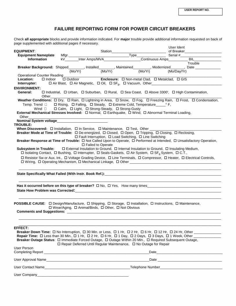
USER REPORT NO.
FAILURE REPORTING FORM FOR POWER CIRCUIT BREAKERS
Check all appropriate blocks and provide information indicated. For major trouble provide additional information requested on back of page supplemented with additional pages if necessary. User Ident EQUIPMENT: Station____________________________ of Breaker___________________ Equipment Nameplate Mfgr._______________________________Type_______________ Serial #_____________________ Information kV_______Inter Amps/MVA___________________Continuous Amps__________ BIL______________ Trouble Breaker Background: Shipped________, Installed________, Maintained_________, Modernized_______, Date _____________ (Mo/Yr) (Mo/Yr) (Mo/Yr) (Mo/Day/Yr) Operational Counter Reading _________________________________________________________________________________ Location: ! Indoor ! Outdoor Enclosure: ! Non-metal Clad, ! Metalclad, ! GIS Interrupter: ! Air Blast, ! Air Magnetic, ! Oil, ! SF6, ! Vacuum, Other____________________________________ ENVIRONMENT: General: ! Industrial, ! Urban, ! Suburban, ! Rural, ! Sea Coast, ! Above 3300', ! High Contamination, Other________________________________________________________________________________________ Weather Conditions: ! Dry, ! Rain, ! Lightning in Area, ! Snow, ! Fog, ! Freezing Rain, ! Frost, ! Condensation, Temp. Trend ! Rising, ! Falling, ! Steady, ! Extreme Cold, Temperature_____° F, Wind ! Calm, ! Light, ! Strong-Steady, ! Strong-Gusty External Mechanical Stresses Involved: ! Normal, ! Earthquake, ! Wind, ! Abnormal Terminal Loading, Other___________________________________________________________________________________________________ Nominal System voltage__________________________ TROUBLE: When Discovered: ! Installation, ! In Service, ! Maintenance, ! Test, Other _____________________________________ Breaker Mode at Time of Trouble: ! De-energized, ! Closed, ! Open, ! Tripping, ! Closing, ! Reclosing, ! Fault Interruption, ! Load Switching, ! Line Switching Breaker Response at Time of Trouble: ! Not Called Upon to Operate, ! Performed at Intended, ! Unsatisfactory Operation, ! Failed to Operate Subsystem in Trouble: ! External Insulation to Ground, ! Internal Insulation to Ground, ! Insulating Medium, ! Isolating Contact, ! Bushing, ! Interrupter, ! Seals-Gaskets, ! Air System, ! SF6 System, ! C.T., ! Resistor Sw or Aux. Int., ! Voltage Grading Device, ! Line Terminals, ! Compressor, ! Heater, ! Electrical Controls, ! Wiring, ! Operating Mechanism, ! Mechanical Linkage, ! Other _______________________________________________
________________________________________________________________________________________________________
State Specifically What Failed (With Instr. Book Ref.):____________________________________________________________
________________________________________________________________________________________________________
Has it occurred before on this type of breaker? ! No, ! Yes, How many times______________________________________ State How Problem was Corrected:___________________________________________________________________________
________________________________________________________________________________________________________ POSSIBLE CAUSE: ! Design/Manufacture, ! Shipping, ! Storage, ! Installation, ! Instructions, ! Maintenance, ! Wear/Aging, ! Animal/Birds, ! Other, ! Not Obvious Comments and Suggestions: _______________________________________________________________________________
________________________________________________________________________________________________________
________________________________________________________________________________________________________ EFFECT: Breaker Down Time: ! No Interruption, ! 30 Min. or Less, ! 1 Hr, ! 2 Hr, ! 6 Hr, ! 12 Hr, ! 24 Hr, Other ______________ Repair Time: ! Less than 30 Min., ! 1 Hr, ! 2 Hr, ! 6 Hr, ! 1 Day, ! 2 Days, ! 3 Days, ! 1 Week, Other ______________ Breaker Outage Status: ! Immediate Forced Outage, ! Outage Within 20 Min., ! Required Subsequent Outage, ! Repair Deferred Until Regular Maintenance, ! No Outage for Repair User Person Completing Report ______________________________________________________Date__________________________________ User Approval Name_____________________________________________________Date _________________________________ User Contact Name____________________________________________Telephone Number________________________________ User Company_______________________________________________
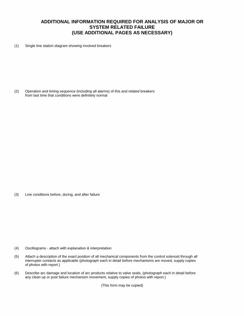
ADDITIONAL INFORMATION REQUIRED FOR ANALYSIS OF MAJOR OR SYSTEM RELATED FAILURE
(USE ADDITIONAL PAGES AS NECESSARY) (1) Single line station diagram showing involved breakers (2) Operation and timing sequence (including all alarms) of this and related breakers from last time that conditions were definitely normal (3) Line conditions before, during, and after failure (4) Oscillograms - attach with explanation & interpretation (5) Attach a description of the exact position of all mechanical components from the control solenoid through all interrupter contacts as applicable (photograph each in detail before mechanisms are moved, supply copies of photos with report.) (6) Describe arc damage and location of arc products relative to valve seals, (photograph each in detail before any clean up or post failure mechanism movement, supply copies of photos with report.)
(This form may be copied)

Intentionally Left Blank
These instructions do not purport to cover all details or variations in equipment nor to provide for every possible contingency to be met in connection with installation, operation or maintenance. Should further information be desired or should particular problems arise which are not covered sufficiently for the purchaser's purposes, the matter should be referred to the General Electric Company.
g GE Electrical Distribution & Control
General Electric Company Switchgear Business Department 510 East Agency Road West Burlington, Iowa 52655 DEH 40368 1100 2000 General Electric Company


![INDEX [ ] · PDF fileArthit Platform Offshore Songkhla Year 2009-2012 Scope of work Preventive Maintenance MV & LV Switchgear • MV Vacuum circuit breaker • MV Vacuum contactor](https://static.fdocument.pub/doc/165x107/5a7041e57f8b9abb538bc8db/index-wwwpmscothwwwpmscothprofileprofile16-3-58pdfpdf.jpg)