mosaic-H Reference Guide
374
mosaic-H Reference Guide Applicable to version 4.9.0 of the Firmware
Transcript of mosaic-H Reference Guide

mosaic-H Reference Guide
Applicable to version 4.9.0 of the Firmware
mosaic-H Reference Guide
2021-03-29
Applicable to version 4.9.0 of the Firmware
© Copyright 2000-2021-03-29 Septentrio NV/SA. All rights reserved.
Septentrio NV
Greenhill Campus, Interleuvenlaan 15i
3001 Leuven, Belgium
http://www.septentrio.com
Phone: +32 16 300 800
Fax: +32 16 221 640
@Septentrio
2
LIST OF CONTENTS
List of Contents
CONTENTS . . . . . . . . . . . . . . . . . . . . . . . . . . . . . . . . . . . . . . . . . . . . . . . . . . . . . . . . . . . . . . . . . . . . . . . . . . . . . . . . . . . . . . . . . . 6
SCOPE . . . . . . . . . . . . . . . . . . . . . . . . . . . . . . . . . . . . . . . . . . . . . . . . . . . . . . . . . . . . . . . . . . . . . . . . . . . . . . . . . . . . . . . . . . . . . . . 7
LIST OF ACRONYMS . . . . . . . . . . . . . . . . . . . . . . . . . . . . . . . . . . . . . . . . . . . . . . . . . . . . . . . . . . . . . . . . . . . . . . . . . . . . . . . . 8
1 How To... 12
1.1 CONNECT TO THE RECEIVER . . . . . . . . . . . . . . . . . . . . . . . . . . . . . . . . . . . . . . . . . . . . . . . . . . . . . . . . . . . . . . . . 13
1.1.1 Via COM Ports . . . . . . . . . . . . . . . . . . . . . . . . . . . . . . . . . . . . . . . . . . . . . . . . . . . . . . . . . . . . . . . . . . . . . 13
1.1.2 Via USB . . . . . . . . . . . . . . . . . . . . . . . . . . . . . . . . . . . . . . . . . . . . . . . . . . . . . . . . . . . . . . . . . . . . . . . . . . . . . 13
1.1.3 Via a TCP/IP Port . . . . . . . . . . . . . . . . . . . . . . . . . . . . . . . . . . . . . . . . . . . . . . . . . . . . . . . . . . . . . . . . . . . 13
1.1.3.1 Ethernet . . . . . . . . . . . . . . . . . . . . . . . . . . . . . . . . . . . . . . . . . . . . . . . . . . . . . . . . . . . . . . . . . 13
1.1.3.2 Ethernet-over-USB . . . . . . . . . . . . . . . . . . . . . . . . . . . . . . . . . . . . . . . . . . . . . . . . . . . . . 14
1.1.3.3 Point-to-Point Link . . . . . . . . . . . . . . . . . . . . . . . . . . . . . . . . . . . . . . . . . . . . . . . . . . . . . 14
1.1.4 Via a Web Browser . . . . . . . . . . . . . . . . . . . . . . . . . . . . . . . . . . . . . . . . . . . . . . . . . . . . . . . . . . . . . . . . 14
1.1.5 Connection Descriptors . . . . . . . . . . . . . . . . . . . . . . . . . . . . . . . . . . . . . . . . . . . . . . . . . . . . . . . . . . 15
1.2 UNDERSTAND THE OUTPUT OF THE RECEIVER . . . . . . . . . . . . . . . . . . . . . . . . . . . . . . . . . . . . . . . . . . . . 16
1.2.1 Proprietary Binary Output (SBF). . . . . . . . . . . . . . . . . . . . . . . . . . . . . . . . . . . . . . . . . . . . . . . . . 16
1.2.2 NMEA . . . . . . . . . . . . . . . . . . . . . . . . . . . . . . . . . . . . . . . . . . . . . . . . . . . . . . . . . . . . . . . . . . . . . . . . . . . . . . . 16
1.3 DEFINE AN SBF OUTPUT STREAM . . . . . . . . . . . . . . . . . . . . . . . . . . . . . . . . . . . . . . . . . . . . . . . . . . . . . . . . . 17
1.4 SAVE THE CONFIGURATION IN NON-VOLATILE MEMORY . . . . . . . . . . . . . . . . . . . . . . . . . . . . . . . . 18
1.5 CONFIGURE THE RECEIVER IN DGPS/RTK-ROVER MODE . . . . . . . . . . . . . . . . . . . . . . . . . . . . . . . . 19
1.6 DETERMINE A GNSS-BASED ATTITUDE FROM THE MAIN AND AUX ANTENNAS . . . . . . . 20
1.7 CONFIGURE THE RECEIVER IN NTRIP CLIENT MODE . . . . . . . . . . . . . . . . . . . . . . . . . . . . . . . . . . . . . 22
1.8 CONFIGURE AN IP SERVER PORT . . . . . . . . . . . . . . . . . . . . . . . . . . . . . . . . . . . . . . . . . . . . . . . . . . . . . . . . . . 23
1.9 CONFIGURE AN IP RECEIVE PORT . . . . . . . . . . . . . . . . . . . . . . . . . . . . . . . . . . . . . . . . . . . . . . . . . . . . . . . . . . 24
1.10 LOG SBF OR NMEA . . . . . . . . . . . . . . . . . . . . . . . . . . . . . . . . . . . . . . . . . . . . . . . . . . . . . . . . . . . . . . . . . . . . . . . . . 25
1.11 LOG RINEX FILES . . . . . . . . . . . . . . . . . . . . . . . . . . . . . . . . . . . . . . . . . . . . . . . . . . . . . . . . . . . . . . . . . . . . . . . . . . . 26
1.12 DOWNLOAD LOG FILES FROM THE RECEIVER . . . . . . . . . . . . . . . . . . . . . . . . . . . . . . . . . . . . . . . . . . . . . 27
1.13 FTP PUSH LOG FILES . . . . . . . . . . . . . . . . . . . . . . . . . . . . . . . . . . . . . . . . . . . . . . . . . . . . . . . . . . . . . . . . . . . . . . . . 29
1.14 COMMUNICATE WITH EXTERNAL EQUIPMENT . . . . . . . . . . . . . . . . . . . . . . . . . . . . . . . . . . . . . . . . . . . . 30
1.15 GENERATE A "PULSE PER SECOND" SIGNAL . . . . . . . . . . . . . . . . . . . . . . . . . . . . . . . . . . . . . . . . . . . . . . 31
1.16 TIME TAG EXTERNAL EVENTS . . . . . . . . . . . . . . . . . . . . . . . . . . . . . . . . . . . . . . . . . . . . . . . . . . . . . . . . . . . . . . . 32
1.17 MONITOR THE RF SPECTRUM . . . . . . . . . . . . . . . . . . . . . . . . . . . . . . . . . . . . . . . . . . . . . . . . . . . . . . . . . . . . . . 33
3
LIST OF CONTENTS
1.18 MANAGE USERS . . . . . . . . . . . . . . . . . . . . . . . . . . . . . . . . . . . . . . . . . . . . . . . . . . . . . . . . . . . . . . . . . . . . . . . . . . . . . 34
1.19 UPGRADE THE RECEIVER . . . . . . . . . . . . . . . . . . . . . . . . . . . . . . . . . . . . . . . . . . . . . . . . . . . . . . . . . . . . . . . . . . . . 35
1.20 CHECK THE CAPABILITIES OF YOUR RECEIVER . . . . . . . . . . . . . . . . . . . . . . . . . . . . . . . . . . . . . . . . . . . . 36
1.21 CHECK OR CHANGE THE PERMISSION FILE . . . . . . . . . . . . . . . . . . . . . . . . . . . . . . . . . . . . . . . . . . . . . . . . 37
2 Operation Details 38
2.1 CHANNEL ALLOCATION AND SIGNAL SELECTION . . . . . . . . . . . . . . . . . . . . . . . . . . . . . . . . . . . . . . . . 38
2.2 GENERATION OF MEASUREMENTS . . . . . . . . . . . . . . . . . . . . . . . . . . . . . . . . . . . . . . . . . . . . . . . . . . . . . . . . . 38
2.2.1 Pilot vs. Data Component . . . . . . . . . . . . . . . . . . . . . . . . . . . . . . . . . . . . . . . . . . . . . . . . . . . . . . . . 39
2.3 TIME MANAGEMENT . . . . . . . . . . . . . . . . . . . . . . . . . . . . . . . . . . . . . . . . . . . . . . . . . . . . . . . . . . . . . . . . . . . . . . . . 40
2.3.1 Free-Running Clock . . . . . . . . . . . . . . . . . . . . . . . . . . . . . . . . . . . . . . . . . . . . . . . . . . . . . . . . . . . . . . . 40
2.3.2 Clock Steering. . . . . . . . . . . . . . . . . . . . . . . . . . . . . . . . . . . . . . . . . . . . . . . . . . . . . . . . . . . . . . . . . . . . . . 41
2.4 COMPUTATION OF POSITION, VELOCITY, AND TIME (PVT SOLUTION) . . . . . . . . . . . . . . . . . 42
2.4.1 SBAS Positioning . . . . . . . . . . . . . . . . . . . . . . . . . . . . . . . . . . . . . . . . . . . . . . . . . . . . . . . . . . . . . . . . . . 43
2.4.2 DGPS Positioning . . . . . . . . . . . . . . . . . . . . . . . . . . . . . . . . . . . . . . . . . . . . . . . . . . . . . . . . . . . . . . . . . . 43
2.4.3 RTK Positioning . . . . . . . . . . . . . . . . . . . . . . . . . . . . . . . . . . . . . . . . . . . . . . . . . . . . . . . . . . . . . . . . . . . . 43
2.4.3.1 Integer Ambiguities (RTK-fixed) . . . . . . . . . . . . . . . . . . . . . . . . . . . . . . . . . . . . . . . 44
2.4.3.2 Floating Ambiguities (RTK-float) . . . . . . . . . . . . . . . . . . . . . . . . . . . . . . . . . . . . . . 44
2.4.4 Transition between PVT Modes . . . . . . . . . . . . . . . . . . . . . . . . . . . . . . . . . . . . . . . . . . . . . . . . . 44
2.4.5 Datum Transformation . . . . . . . . . . . . . . . . . . . . . . . . . . . . . . . . . . . . . . . . . . . . . . . . . . . . . . . . . . . 44
2.4.5.1 Transformation to Regional Datum . . . . . . . . . . . . . . . . . . . . . . . . . . . . . . . . . . 44
2.4.5.2 Transformation to Local Datum . . . . . . . . . . . . . . . . . . . . . . . . . . . . . . . . . . . . . . 45
2.5 ANTENNA EFFECTS . . . . . . . . . . . . . . . . . . . . . . . . . . . . . . . . . . . . . . . . . . . . . . . . . . . . . . . . . . . . . . . . . . . . . . . . . . 45
2.5.1 Antenna Effects in Rover Mode . . . . . . . . . . . . . . . . . . . . . . . . . . . . . . . . . . . . . . . . . . . . . . . . . 46
3 Command Line Reference 48
3.1 COMMAND LINE INTERFACE OUTLINE . . . . . . . . . . . . . . . . . . . . . . . . . . . . . . . . . . . . . . . . . . . . . . . . . . . . 49
3.1.1 Command Types . . . . . . . . . . . . . . . . . . . . . . . . . . . . . . . . . . . . . . . . . . . . . . . . . . . . . . . . . . . . . . . . . . 49
3.1.2 Command Line Syntax. . . . . . . . . . . . . . . . . . . . . . . . . . . . . . . . . . . . . . . . . . . . . . . . . . . . . . . . . . . . 49
3.1.3 Command Replies . . . . . . . . . . . . . . . . . . . . . . . . . . . . . . . . . . . . . . . . . . . . . . . . . . . . . . . . . . . . . . . . . 50
3.1.4 Command Syntax Tables . . . . . . . . . . . . . . . . . . . . . . . . . . . . . . . . . . . . . . . . . . . . . . . . . . . . . . . . . 51
3.2 COMMAND DEFINITIONS . . . . . . . . . . . . . . . . . . . . . . . . . . . . . . . . . . . . . . . . . . . . . . . . . . . . . . . . . . . . . . . . . . . 54
3.2.1 Receiver Administration . . . . . . . . . . . . . . . . . . . . . . . . . . . . . . . . . . . . . . . . . . . . . . . . . . . . . . . . . . 54
3.2.2 Standby and Sleep Configuration . . . . . . . . . . . . . . . . . . . . . . . . . . . . . . . . . . . . . . . . . . . . . . . 71
3.2.3 User Management . . . . . . . . . . . . . . . . . . . . . . . . . . . . . . . . . . . . . . . . . . . . . . . . . . . . . . . . . . . . . . . . 72
3.2.4 Tracking and Measurement Generation . . . . . . . . . . . . . . . . . . . . . . . . . . . . . . . . . . . . . . . 77
3.2.5 Frontend and Interference Mitigation . . . . . . . . . . . . . . . . . . . . . . . . . . . . . . . . . . . . . . . . . . 85
3.2.6 Navigation Filter . . . . . . . . . . . . . . . . . . . . . . . . . . . . . . . . . . . . . . . . . . . . . . . . . . . . . . . . . . . . . . . . . . . 90
3.2.7 Attitude Determination. . . . . . . . . . . . . . . . . . . . . . . . . . . . . . . . . . . . . . . . . . . . . . . . . . . . . . . . . . .111
3.2.8 Datum Definition . . . . . . . . . . . . . . . . . . . . . . . . . . . . . . . . . . . . . . . . . . . . . . . . . . . . . . . . . . . . . . . . . .114
3.2.9 Transformation to Local Coordinates . . . . . . . . . . . . . . . . . . . . . . . . . . . . . . . . . . . . . . . . . .119
3.2.10 Timing and Time Management . . . . . . . . . . . . . . . . . . . . . . . . . . . . . . . . . . . . . . . . . . . . . . . . . .123
3.2.11 Station Settings . . . . . . . . . . . . . . . . . . . . . . . . . . . . . . . . . . . . . . . . . . . . . . . . . . . . . . . . . . . . . . . . . . . .128
3.2.12 General Input/Output . . . . . . . . . . . . . . . . . . . . . . . . . . . . . . . . . . . . . . . . . . . . . . . . . . . . . . . . . . . .131
3.2.13 NTRIP Settings . . . . . . . . . . . . . . . . . . . . . . . . . . . . . . . . . . . . . . . . . . . . . . . . . . . . . . . . . . . . . . . . . . . . .150
3.2.14 NMEA Configuration . . . . . . . . . . . . . . . . . . . . . . . . . . . . . . . . . . . . . . . . . . . . . . . . . . . . . . . . . . . . . .153
3.2.15 SBF Configuration . . . . . . . . . . . . . . . . . . . . . . . . . . . . . . . . . . . . . . . . . . . . . . . . . . . . . . . . . . . . . . . . .159
4
LIST OF CONTENTS
3.2.16 RTCM v2.x Settings . . . . . . . . . . . . . . . . . . . . . . . . . . . . . . . . . . . . . . . . . . . . . . . . . . . . . . . . . . . . . . . .166
3.2.17 RTCM v3.x Settings . . . . . . . . . . . . . . . . . . . . . . . . . . . . . . . . . . . . . . . . . . . . . . . . . . . . . . . . . . . . . . . .168
3.2.18 CMR v2.0 Settings . . . . . . . . . . . . . . . . . . . . . . . . . . . . . . . . . . . . . . . . . . . . . . . . . . . . . . . . . . . . . . . . .170
3.2.19 Internal Disk Logging . . . . . . . . . . . . . . . . . . . . . . . . . . . . . . . . . . . . . . . . . . . . . . . . . . . . . . . . . . . . .171
3.2.20 FTP Push of Log Files. . . . . . . . . . . . . . . . . . . . . . . . . . . . . . . . . . . . . . . . . . . . . . . . . . . . . . . . . . . . . .182
4 SBF Reference 185
4.1 SBF OUTLINE . . . . . . . . . . . . . . . . . . . . . . . . . . . . . . . . . . . . . . . . . . . . . . . . . . . . . . . . . . . . . . . . . . . . . . . . . . . . . . . .186
4.1.1 SBF Block Header Format . . . . . . . . . . . . . . . . . . . . . . . . . . . . . . . . . . . . . . . . . . . . . . . . . . . . . . . .186
4.1.2 SBF Block Names and Numbers. . . . . . . . . . . . . . . . . . . . . . . . . . . . . . . . . . . . . . . . . . . . . . . . .186
4.1.3 SBF Block Time Stamp (TOW and WNc) . . . . . . . . . . . . . . . . . . . . . . . . . . . . . . . . . . . . . . . .187
4.1.4 Sub-blocks. . . . . . . . . . . . . . . . . . . . . . . . . . . . . . . . . . . . . . . . . . . . . . . . . . . . . . . . . . . . . . . . . . . . . . . . . .188
4.1.5 Padding Bytes. . . . . . . . . . . . . . . . . . . . . . . . . . . . . . . . . . . . . . . . . . . . . . . . . . . . . . . . . . . . . . . . . . . . . .188
4.1.6 SBF Revision Number . . . . . . . . . . . . . . . . . . . . . . . . . . . . . . . . . . . . . . . . . . . . . . . . . . . . . . . . . . . . .188
4.1.7 Do-Not-Use Value . . . . . . . . . . . . . . . . . . . . . . . . . . . . . . . . . . . . . . . . . . . . . . . . . . . . . . . . . . . . . . . . .188
4.1.8 Output Rate . . . . . . . . . . . . . . . . . . . . . . . . . . . . . . . . . . . . . . . . . . . . . . . . . . . . . . . . . . . . . . . . . . . . . . . .188
4.1.9 Satellite ID and GLONASS Frequency Number . . . . . . . . . . . . . . . . . . . . . . . . . . . . . . . .189
4.1.10 Signal Type . . . . . . . . . . . . . . . . . . . . . . . . . . . . . . . . . . . . . . . . . . . . . . . . . . . . . . . . . . . . . . . . . . . . . . . . .190
4.1.11 Channel Numbering . . . . . . . . . . . . . . . . . . . . . . . . . . . . . . . . . . . . . . . . . . . . . . . . . . . . . . . . . . . . . .191
4.1.12 Decoding of SBF Blocks. . . . . . . . . . . . . . . . . . . . . . . . . . . . . . . . . . . . . . . . . . . . . . . . . . . . . . . . . . .191
4.2 SBF BLOCK DEFINITIONS . . . . . . . . . . . . . . . . . . . . . . . . . . . . . . . . . . . . . . . . . . . . . . . . . . . . . . . . . . . . . . . . . . .193
4.2.1 Measurement Blocks . . . . . . . . . . . . . . . . . . . . . . . . . . . . . . . . . . . . . . . . . . . . . . . . . . . . . . . . . . . . .193
4.2.2 Navigation Page Blocks . . . . . . . . . . . . . . . . . . . . . . . . . . . . . . . . . . . . . . . . . . . . . . . . . . . . . . . . . . .208
4.2.3 GPS Decoded Message Blocks. . . . . . . . . . . . . . . . . . . . . . . . . . . . . . . . . . . . . . . . . . . . . . . . . . .216
4.2.4 GLONASS Decoded Message Blocks . . . . . . . . . . . . . . . . . . . . . . . . . . . . . . . . . . . . . . . . . . . .221
4.2.5 Galileo Decoded Message Blocks . . . . . . . . . . . . . . . . . . . . . . . . . . . . . . . . . . . . . . . . . . . . . . .224
4.2.6 BeiDou Decoded Message Blocks. . . . . . . . . . . . . . . . . . . . . . . . . . . . . . . . . . . . . . . . . . . . . . .233
4.2.7 QZSS Decoded Message Blocks . . . . . . . . . . . . . . . . . . . . . . . . . . . . . . . . . . . . . . . . . . . . . . . . .238
4.2.8 SBAS L1 Decoded Message Blocks . . . . . . . . . . . . . . . . . . . . . . . . . . . . . . . . . . . . . . . . . . . . . .241
4.2.9 Position, Velocity and Time Blocks . . . . . . . . . . . . . . . . . . . . . . . . . . . . . . . . . . . . . . . . . . . . . .255
4.2.10 GNSS Attitude Blocks . . . . . . . . . . . . . . . . . . . . . . . . . . . . . . . . . . . . . . . . . . . . . . . . . . . . . . . . . . . . .293
4.2.11 Receiver Time Blocks . . . . . . . . . . . . . . . . . . . . . . . . . . . . . . . . . . . . . . . . . . . . . . . . . . . . . . . . . . . . .297
4.2.12 External Event Blocks . . . . . . . . . . . . . . . . . . . . . . . . . . . . . . . . . . . . . . . . . . . . . . . . . . . . . . . . . . . . .299
4.2.13 Differential Correction Blocks . . . . . . . . . . . . . . . . . . . . . . . . . . . . . . . . . . . . . . . . . . . . . . . . . . .314
4.2.14 Status Blocks . . . . . . . . . . . . . . . . . . . . . . . . . . . . . . . . . . . . . . . . . . . . . . . . . . . . . . . . . . . . . . . . . . . . . . .319
4.2.15 Miscellaneous Blocks . . . . . . . . . . . . . . . . . . . . . . . . . . . . . . . . . . . . . . . . . . . . . . . . . . . . . . . . . . . . .342
4.3 SBF CHANGE LOG . . . . . . . . . . . . . . . . . . . . . . . . . . . . . . . . . . . . . . . . . . . . . . . . . . . . . . . . . . . . . . . . . . . . . . . . . . .350
A Attitude Angles 351
B List of SBF Blocks 353
C List of NMEA Sentences 356
C.1 PROPRIETARY NMEA SENTENCES . . . . . . . . . . . . . . . . . . . . . . . . . . . . . . . . . . . . . . . . . . . . . . . . . . . . . . . . .357
C.1.1 HRP : Heading, Roll, Pitch . . . . . . . . . . . . . . . . . . . . . . . . . . . . . . . . . . . . . . . . . . . . . . . . . . . . . . . .357
C.1.2 RBD : Rover-Base Direction . . . . . . . . . . . . . . . . . . . . . . . . . . . . . . . . . . . . . . . . . . . . . . . . . . . . . .358
C.1.3 RBP : Rover-Base Position . . . . . . . . . . . . . . . . . . . . . . . . . . . . . . . . . . . . . . . . . . . . . . . . . . . . . . . .358
C.1.4 RBV : Rover-Base Velocity . . . . . . . . . . . . . . . . . . . . . . . . . . . . . . . . . . . . . . . . . . . . . . . . . . . . . . . .359
C.1.5 SNC : NTRIP Client Status. . . . . . . . . . . . . . . . . . . . . . . . . . . . . . . . . . . . . . . . . . . . . . . . . . . . . . . . .359
C.1.6 TFM : Used RTCM Coordinate Transformation Messages . . . . . . . . . . . . . . . . . . .360
5
LIST OF CONTENTS
D List of CMR and RTCM Messages 361
D.1 CMR MESSAGES . . . . . . . . . . . . . . . . . . . . . . . . . . . . . . . . . . . . . . . . . . . . . . . . . . . . . . . . . . . . . . . . . . . . . . . . . . . . .361
D.2 RTCM V2.X MESSAGES . . . . . . . . . . . . . . . . . . . . . . . . . . . . . . . . . . . . . . . . . . . . . . . . . . . . . . . . . . . . . . . . . . . . .361
D.3 RTCM V3.X MESSAGES . . . . . . . . . . . . . . . . . . . . . . . . . . . . . . . . . . . . . . . . . . . . . . . . . . . . . . . . . . . . . . . . . . . . .362
INDEX OF COMMANDS . . . . . . . . . . . . . . . . . . . . . . . . . . . . . . . . . . . . . . . . . . . . . . . . . . . . . . . . . . . . . . . . . . . . . . . . . . . . .364
INDEX OF SBF BLOCKS . . . . . . . . . . . . . . . . . . . . . . . . . . . . . . . . . . . . . . . . . . . . . . . . . . . . . . . . . . . . . . . . . . . . . . . . . . . .372
6
SCOPE
Scope
This document contains reference information about the receiver firmware.
Chapter 1 provides a set of step-by-step "how-to’s" to help you find your way around the
receiver’s commands and logs.
Chapter 2 provides some background on the main algorithms running in the receiver and on
the way to configure them.
Chapter 3 contains the complete description of the user command interface.
Chapter 4 contains the complete description of the SBF format.
Typographical Conventions
abc User command name. Clicking a command name redirects to the full command
description.
abc Command argument name.
abc Command replies.
SBF block name or SBF field name. Clicking an SBF block name redirects to the full
SBF block description.
7
LIST OF ACRONYMS
List of Acronyms
Abbreviation Description
AGC Automatic Gain Control
ARP Antenna Reference Point
ASCII American Standard Code for Information Interchange
ASN.1 Abstract Syntax Notation One
BeiDou BeiDou Navigation System
BGD Broadcast Group Delay
CA Coarse Acquisition
CGGTTS Common GPS GLONASS Time Transfer Standard
CMR Compact Measurement Record
COG Course Over Ground
CPU Central Processing Unit
CRC Cyclic Redundancy Check
DGPS Differential GPS
DHCP Dynamic Host Configuration Protocol
DLL Dynamically Linked Library
DNS Domain Name Server
DOP Dilution Of Precision
DVS Data Validity Status
ECEF Earth-Centered Earth-Fixed
EGNOS European Geostationary Navigation Overlay System
ENU East-North-Up
FTP File Transfer Protocol
GEO Geostationary Earth Orbiter
8
LIST OF ACRONYMS
GLONASS Global Orbiting Navigation Satellite System
GNSS Global Navigation Satellite System
GPS Global Positioning System
GST Galileo System Time
GUI Graphical User Interface
HDOP Horizontal DOP
HMI Hazardously Misleading Information
HPCA HMI Probability Computation Algorithm
HPL Horizontal Protection Level
HS Health Status
ICD Interface Control Document
IEEE Institute of Electrical and Electronics Engineers
IERS International Earth Rotation Service
IF Intermediate Frequency
IGP Ionospheric Grid Point
IGS International GPS Service
IMU Inertial Measurement Unit
INS Inertial Navigation System
IODC Issue of Data - Clock
IODE Issue Of Data Ephemeris
IP Internet Protocol
IRNSS Indian Regional Navigational Satellite System
ITRF International Terrestrial Reference Frame
ITRS International Terrestrial Reference System
LBand L-Band Receiver
L1 L1 carrier
L2 L2 carrier
L2C L2C code
LED Light Emitting Diode
LSB Least Significant Bit
MIB Management Information Base
MSB Most Significant Bits
MT Message Type
9
LIST OF ACRONYMS
NATO North Atlantic Treaty Organisation
NAV Navigation
NavIC Navigation with Indian Constellation
NAVSTAR Navigation Satellite Timing And Ranging
NMEA National Marine Electronics Association
P P(Y) code
P1 P1 code
P2 P2 code
PC Phase Center
PDOP Position DOP
PLL Phase Locked Loop
PPP Precise Point Positioning
PPS Pulse Per Second
PRC Pseudorange Correction
PRN Pseudo Random Noise
PVT Position, Velocity and Time
QZSS Quasi-Zenith Satellite System
RAIM Receiver Autonomous Integrity Monitoring
RINEX Receiver Independent Exchange Format
RTCA Radio Technical Commission for Aeronautics
RTCM Radio Technical Commission for Maritime Services
RTK Real-Time Kinematic
SBAS Space-Based Augmentation System
SBF Septentrio Binary Format
SIS Signal In Space
SISA Signal in Space Accuracy
SNMP Simple Network Management Protocol
SV Space Vehicle
SVID Space Vehicle ID
TDOP Time DOP
TOW Time Of Week
UDRE User Differential Range Error
UERE User Equivalent Range Error
10
LIST OF ACRONYMS
UHF Ultra High Frequency
URA User Range Accuracy
USB Universal Serial Bus
UTC Coordinated Universal Time
VDOP Vertical DOP
VPL Vertical Protection Level
VRS Virtual Reference Station
WAAS Wide Area Augmentation System
WGS84 World Geodetic System 1984
WN Week Number
WNc Week number
XERL External Reliability Levels
XOR Exclusive OR
11
1 How To...
Chapter 1
How To...
This chapter contains step-by-step instructions to help you with typical tasks. It will help you
to familiarize yourself with the receiver commands without going into too much detail.
For a comprehensive description of the command set, refer to chapter 3. You can also click
on any command or SBF block name in this manual to be redirected to the full description
of that command or SBF block.
You can enter user commands in many different ways:
• Commands can be accessed graphically through menus in RxControl and in the web
interface (see section 1.1.4).
• Using the Data Link program provided in the RxTools suite (or any suitable termi-
nal emulation program), you can enter commands manually through one of the re-
ceiver input ports (see section 1.1). In this chapter, user commands are referred to
by their full name for readability. When typing the command, you can always use
the short mnemonic equivalent to save typing effort. For instance, instead of typing
setCOMSettings, you can type scs.• You can type commands or mnemonics in the console window of RxControl (menuTools > Expert Console) or of the web interface (menu Admin > Expert Console).
Depending on the capabilities of your particular receiver (see section 1.20), some of the user
commands, SBF blocks or communication interfaces described in this document may not be
supported.
12
1 How To...
1.1 Connect to the Receiver
1.1.1 Via COM Ports
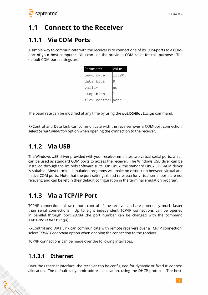
A simple way to communicate with the receiver is to connect one of its COM-ports to a COM-
port of your host computer. You can use the provided COM cable for this purpose. The
default COM-port settings are:
Parameter Value
baud rate 115200
data bits 8
parity no
stop bits 1
flow control none
The baud rate can be modified at any time by using the setCOMSettings command.
RxControl and Data Link can communicate with the receiver over a COM-port connection:
select Serial Connection option when opening the connection to the receiver.
1.1.2 Via USB
The Windows USB driver provided with your receiver emulates two virtual serial ports, which
can be used as standard COM ports to access the receiver. The Windows USB diver can be
installed through the RxTools software suite. On Linux, the standard Linux CDC-ACM driver
is suitable. Most terminal emulation programs will make no distinction between virtual and
native COM ports. Note that the port settings (baud rate, etc) for virtual serial ports are not
relevant, and can be left in their default configuration in the terminal emulation program.
1.1.3 Via a TCP/IP Port
TCP/IP connections allow remote control of the receiver and are potentially much faster
than serial connections. Up to eight independent TCP/IP connections can be opened
in parallel through port 28784 (the port number can be changed with the command
setIPPortSettings).
RxControl and Data Link can communicate with remote receivers over a TCP/IP connection:
select TCP/IP Connection option when opening the connection to the receiver.TCP/IP connections can be made over the following interfaces.
1.1.3.1 Ethernet
Over the Ethernet interface, the receiver can be configured for dynamic or fixed IP address
allocation. The default is dynamic address allocation, using the DHCP protocol. The host-
13
1 How To...
name is mosaic-h-xxxxxxx, where xxxxxxx consists of the last seven digits of the serialnumber of the receiver.
Dynamic IP address allocation requires the availability of a DHCP server in your local network.
In the absence of a DHCP server, or when a fixed IP address is desirable, it is possible to
disable the DHCP client and use a fixed address. This is done using the setIPSettingscommand.
1.1.3.2 Ethernet-over-USB
When an USB cable is connected, the receiver supports Ethernet-over-USB. The IP address
allocated to the Ethernet-over-USB interface is 192.168.3.1. That address cannot bechanged, so that this feature is only to be used when a single receiver is connected to your
computer.
1.1.3.3 Point-to-Point Link
The receiver incorporates a point-to-point protocol server, by which it can accept TCP/IP con-
nections over a serial link.
Configuring the point-to-point server is done with the setPointToPoint command. Forexample, to set up a point-to-point communication over COM1, with the server (i.e. the
receiver) having address 192.168.60.1 and the client having address 192.168.60.2, and using
CHAP authentication with password “mypwd”, use this command:
setPointToPoint, P2PP1, Server, COM1, 192.168.60.2, 192.168.60.1,CHAP, mypwd <CR>
If the client is a Linux computer, make sure the password is set in the
/etc/ppp/chap-secrets file. For example, the contents of that file could be as
follows:
Assuming that the serial cable is connected to the first serial port of your PC, and that the
receiver’s COM1 port is left in its default configuration (115200 baud and no hardware flow
control), the client PPP daemon can be started with the following Linux command:
pppd /dev/ttyS0 115200 nocrtscts local
After a few seconds, the PPP link is established and it is possible to access the receiver at IP
address 192.168.60.1.
1.1.4 Via a Web Browser
The receiver can be controlled and configured using a web browser. The hostname or fixed
IP address is defined as explained in section 1.1.3.
14

1 How To...
For example, if your receiver’s hostname is mosaic-h-1234567, simply use the followingURL in your preferred web browser:
http://mosaic-h-1234567
or, for a secure connection:
https://mosaic-h-1234567
The https certificate (.pem file) can be uploaded through the Communication > WebServer/TLSmenu of the web interface.Most user commands described in section 3.2 can be accessed graphically from the web
interface. You can also go to Admin > Expert Control > Expert Console to manually type ASCIIcommands and view replies.
By default, the web interface provides unrestricted read and write access to the receiver.
This can be changed, as further explained in section 1.18 of this document.
Note that a lightweight (text only) version of the web interface is available by appending
/lite to the URL, for example:
http://mosaic-h-1234567/lite
1.1.5 Connection Descriptors
Receiver connections are identified by their connection descriptor (CD). The different con-
nection descriptors are shown in the table below. The three rightmost columns indicate the
direction (input or output or both), and whether the connection can accept user command
input.
CD Description In Out Cmd
COMx one of the serial ports • • •
USBx one of the USB-device serial ports • • •
DSK1 the internal disk. See section 1.10 •
IP1x one of the TCP/IP connections • • •
NTRx one of the NTRIP connections. Input in NTRIP client mode(section 1.7)
•
IPSx one of the IP server connections. See section 1.8 • • •
IPRx one of the IP receive connections. See section 1.9 • • •
15
1 How To...
1.2 Understand the Output of the Receiver
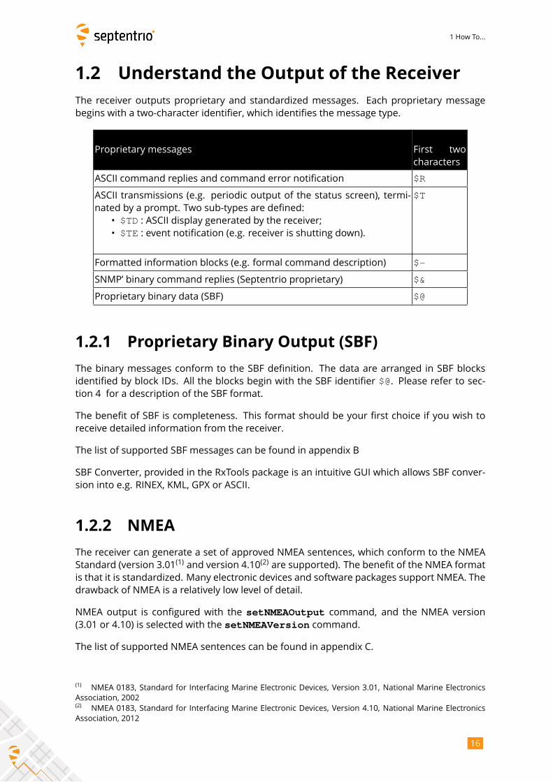
The receiver outputs proprietary and standardized messages. Each proprietary message
begins with a two-character identifier, which identifies the message type.
Proprietary messages First two
characters
ASCII command replies and command error notification $R
ASCII transmissions (e.g. periodic output of the status screen), termi-
nated by a prompt. Two sub-types are defined:
• $TD : ASCII display generated by the receiver;• $TE : event notification (e.g. receiver is shutting down).
$T
Formatted information blocks (e.g. formal command description) $-
SNMP’ binary command replies (Septentrio proprietary) $&
Proprietary binary data (SBF) $@
1.2.1 Proprietary Binary Output (SBF)
The binary messages conform to the SBF definition. The data are arranged in SBF blocks
identified by block IDs. All the blocks begin with the SBF identifier $@. Please refer to sec-tion 4 for a description of the SBF format.
The benefit of SBF is completeness. This format should be your first choice if you wish to
receive detailed information from the receiver.
The list of supported SBF messages can be found in appendix B
SBF Converter, provided in the RxTools package is an intuitive GUI which allows SBF conver-
sion into e.g. RINEX, KML, GPX or ASCII.
1.2.2 NMEA
The receiver can generate a set of approved NMEA sentences, which conform to the NMEA
Standard (version 3.01(1)and version 4.10
(2)are supported). The benefit of the NMEA format
is that it is standardized. Many electronic devices and software packages support NMEA. The
drawback of NMEA is a relatively low level of detail.
NMEA output is configured with the setNMEAOutput command, and the NMEA version(3.01 or 4.10) is selected with the setNMEAVersion command.
The list of supported NMEA sentences can be found in appendix C.
(1)NMEA 0183, Standard for Interfacing Marine Electronic Devices, Version 3.01, National Marine Electronics
Association, 2002(2)
NMEA 0183, Standard for Interfacing Marine Electronic Devices, Version 4.10, National Marine Electronics
Association, 2012
16
1 How To...
1.3 Define an SBF Output Stream
As an example, this section explains how to use the command line interface to configure the
receiver to output the MeasEpoch SBF block at 10 Hz, the PVTCartesian SBF block at 1 Hz,and the GPSNav block at its On-Change rate (see section 4.1.8 for more details on the SBFoutput rate). In this example, we will assume that these blocks must be output through the
USB2 connection.
1. First make sure that the USB2 connection is configured for SBF output (this is the
default). In case this is not so, you should invoke:
setDataInOut,USB2,,+SBF <CR>
2. Scheduling SBF blocks for output is done by defining so-called "SBF streams". At least
10 SBF streams can be defined by the user. A stream consists of a set of SBF blocks
that need to be output at a given rate through a given connection. By default, all
streams are empty, and no SBF blocks are output. For our example, we will need to
use two streams. Defining these SBF streams involves the setSBFOutput command:setSBFOutput,Stream1,USB2,MeasEpoch+GPSNav,msec100 <CR>setSBFOutput,Stream2,USB2,PVTCartesian,sec1 <CR>Note that the rate specified with the setSBFOutput command (msec100 or sec1above) only applies to the blocks that support a flexible output rate (see appendix B). TheGPSNav block does not support flexible rate: it is always output at its “On-Change” rateregardless of the stream rate. For this reason, in the above example, we could equally haveenabled GPSNav in Stream2.
3. To stop outputting SBF on a given connection, you can either redefine or empty the
corresponding streams:
setSBFOutput,Stream1,USB2,none <CR>setSBFOutput,Stream2,USB2,none <CR>A second possibility is to disable all SBF messages on that connection:
setDataInOut,USB2,,-SBF <CR>
Note that the exeSBFOnce command can be used to output a set of blocks once, instead ofat regular interval. This is typically used to output all currently available satellite ephemerides
at once. For example, the following command instructs the receiver to output all known GPS,
GLONASS, Galileo and BeiDou ephemerides over USB2:
exeSBFOnce, USB2, GPS+GLO+GAL+BDS <CR>
This is a one-time action: the requested blocks are inserted in the stream, and then the
normal flow of blocks as defined with setSBFOutput resumes. When logging the SBFstream for post-processing, it is a good practice to request all satellite ephemerides with
the exeSBFOnce command when starting a new log file. Make sure however not to requestmeasurement or PVT blocks with exeSBFOnce when these blocks are also enabled withsetSBFOutput as it could cause the same epoch to be duplicated in the log file. Somepost-processing tools may not work properly when the same epoch is repeated twice.
17
1 How To...
1.4 Save the Configuration in Non-Volatile
Memory
The receiver configuration includes all the user-selectable parameters, such as the elevation
mask, the PVT mode, the COM port settings,...
By default, the receiver starts up in its factory default configuration. The factory defaults
for each of the receiver parameters are underlined for each argument of each command in
section 3.2
The current receiver configuration can be checked with the lstConfigFile command:lstConfigFile, Current <CR>
At any time, it is possible to save the current configuration into non-volatile memory, in
order to force the receiver to always start up in that configuration. To do so, the following
command should be entered:
exeCopyConfigFile,Current,Boot <CR>
To revert to the default setting where the receiver starts in the default configuration, you
should use:
exeCopyConfigFile,RxDefault,Boot <CR>
18
1 How To...
1.5 Configure the Receiver in DGPS/RTK-Rover
Mode
The receiver computes a DGPS and/or an RTK solution when it receives the relevant dif-
ferential correction messages on one of its connections. The list of supported differential
correction messages can be found in appendix D.
To configure the receiver in DGPS/RTK-rover mode, the following has to be done:
1. Make sure that at least one of the receiver connections is receiving differential
corrections. Any input connection listed in section 1.1.5 is suitable. When using a
serial connection, make sure to configure the baud rate to match the baud rate of the
incoming RTCM stream. For instance if the incoming RTCM stream is received through
COM2 at a baud rate of 9600 baud, use:
setCOMSettings,COM2,baud9600 <CR>
2. The receiver automatically detects the format of the differential corrections (RTCM or
CMR) and switches between standalone, DGPS or RTK modes according to the type
of corrections it receives, provided these modes are enabled with the setPVTModecommand (all modes are enabled by default).
Refer to sections 2.4.2 and 2.4.3 for further details on the DGPS and RTK positioning mode.
19
1 How To...
1.6 Determine a GNSS-Based Attitude from
the Main and Aux Antennas
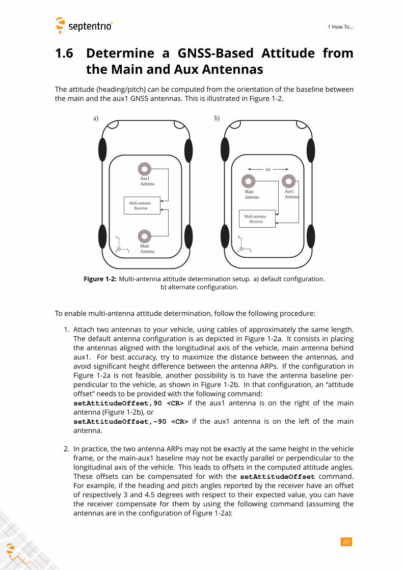
The attitude (heading/pitch) can be computed from the orientation of the baseline between
the main and the aux1 GNSS antennas. This is illustrated in Figure 1-2.
Multi-antenna Receiver
X
Y Z
Main Antenna
Aux1 Antenna
Multi-antenna Receiver
X
Y Z
Main Antenna
Aux1 Antenna
a) b)
1m
Figure 1-2: Multi-antenna attitude determination setup. a) default configuration.
b) alternate configuration.
To enable multi-antenna attitude determination, follow the following procedure:
1. Attach two antennas to your vehicle, using cables of approximately the same length.
The default antenna configuration is as depicted in Figure 1-2a. It consists in placing
the antennas aligned with the longitudinal axis of the vehicle, main antenna behind
aux1. For best accuracy, try to maximize the distance between the antennas, and
avoid significant height difference between the antenna ARPs. If the configuration in
Figure 1-2a is not feasible, another possibility is to have the antenna baseline per-
pendicular to the vehicle, as shown in Figure 1-2b. In that configuration, an “attitude
offset” needs to be provided with the following command:
setAttitudeOffset,90 <CR> if the aux1 antenna is on the right of the mainantenna (Figure 1-2b), or
setAttitudeOffset,-90 <CR> if the aux1 antenna is on the left of the mainantenna.
2. In practice, the two antenna ARPs may not be exactly at the same height in the vehicle
frame, or the main-aux1 baseline may not be exactly parallel or perpendicular to the
longitudinal axis of the vehicle. This leads to offsets in the computed attitude angles.
These offsets can be compensated for with the setAttitudeOffset command.For example, if the heading and pitch angles reported by the receiver have an offset
of respectively 3 and 4.5 degrees with respect to their expected value, you can have
the receiver compensate for them by using the following command (assuming the
antennas are in the configuration of Figure 1-2a):
20
1 How To...
setAttitudeOffset,3,4.5 <CR>
3. Specify that the attitude has to be computed in multi-antenna mode:
setGNSSAttitude,MultiAntenna <CR>
The GNSS-based attitude angles (heading and pitch) are available in the AttEuler SBF blockor in the HDT and HRP NMEA sentences. Note that, in the case where the antenna baseline
is perpendicular to the vehicle longitudinal axis, the “pitch” angle is to be interpreted as a
“roll” angle.
21
1 How To...
1.7 Configure the Receiver in NTRIP Client
Mode
In this section, we show how to configure the receiver to receive and use RTK corrections
from an NTRIP caster. In the example below, the NTRIP caster and Mount Point details are
as follows:
• NTRIP caster hostname: ntrip.example.com
• NTRIP caster port: 2101
• User name/password for basic authentication: USER / PASSWD
• Mount Point: LEUV1
• TLS: enabled and the caster is trusted by a public certification authority
1. Configure one of the NTRIP connections (see section 1.1.5) for communication with the
NTRIP caster in client mode. Here, we assume that the first NTRIP connection (NTR1)is free and can be used for that purpose:
setNTRIPSettings,NTR1,Client,ntrip.example.com,2101,USER,PASSWD,LEUV1<CR>
2. To enable TLS for NTR1, use:setNtripTlsSettings,NTR1,on,"" <CR>
3. The receiver will automatically receive and decode the RTK corrections from the
NTRIP caster and switch to RTK positioning mode, unless RTK is disabled with the
setPVTMode command.
4. Closing the NTRIP connection is done with the following command:
setNTRIPSettings,NTR1,off <CR>
The status of the NTRIP client connection is reported in the NTRIPClientStatus SBF block.
22
1 How To...
1.8 Configure an IP Server Port
In this example, we show how to configure the receiver such that any client connecting to
TCP/IP port 28785 will receive the NMEA GGA message at a 1-second interval.
1. Configure one of the IP server connections (see section 1.1.5) to listen to port 28785.
Here, we assume that the first IP server connection (IPS1) is free:setIPServerSettings,IPS1,28785,TCP <CR>
2. Output the GGA NMEA message to the IPS1 connection, at a 1-Hz rate:setNMEAOutput,Stream1,IPS1,GGA,sec1 <CR>
3. Make sure that NMEA output is enabled on the IPS1 connection. It is enabled by
default, but in case your receiver is not in its default configuration, you should invoke:
setDataInOut,IPS1,,+NMEA <CR>
A way to check the IP server functionality is to enter the URL
http://mosaic-h-xxxxxxx:28785 in your preferred web browser (replace
mosaic-h-xxxxxxx by the hostname of your particular receiver). You should see
the NMEA GGA message coming every second.
Note that up to eight clients can concurrently connect to the same IP server port.
The example above showed how to set up a TCP server. It is also possible to configure the
receiver in UDP server mode. For example, to broadcast the GGA message to any UDP client
listening to its port 28785, the command in step 1. above must be replaced by:
setIPServerSettings,IPS1,28785,UDP,255.255.255.255 <CR>
Conversely, the receiver can be configured to automatically receive data from an IP server.
This is explained in section 1.9.
23
1 How To...
1.9 Configure an IP Receive Port
The receiver can be configured to automatically receive data (typically differential correc-
tions) from an IP server. In this example, we show how to connect to an IP server having the
hostname MyServer and using port 28786.
1. Configure one of the IP receive connections (see section 1.1.5) to listen to port 28786
of MyServer. Here, we assume that the first IP receive connection (IPR1) is free:setIPReceiveSettings,IPR1,28786,TCP2Way,MyServer <CR>
2. If the data stream from the IP server contains differential corrections in CMR or
RTCM format, the receiver will automatically decode them and use them in the PVT
processing.
3. To close the connection, enter the following command:
setIPReceiveSettings,IPR1,0 <CR>
The TCP connection initiated by the receiver is bidirectional. Once the connection is estab-
lished, the receiver accepts input data from the server (as shown above), but it can also send
data to the server, or process user commands from the server.
The example showed how to set up a TCP connection with the server. The receiver can
also listen to incoming UDP messages. In that case, the connection is unidirectional and the
server address or hostname must not be specified. For example, to listen to UDP messages
on port 28786, use the command:
setIPReceiveSettings,IPR1,28786,UDP <CR>
24
1 How To...
1.10 Log SBF or NMEA
The connection descriptor (see section 1.1.5) associated to the internal disk is "DSK1". En-abling SBF or NMEA logging on the internal disk involves the following steps:
1. By default, the receiver logs SBF blocks into a file named "log.sbf" and NMEAsentences into a file named “log.nma” . You can specify any other fixed or auto-incrementing file name, or you can select the IGS/RINEX naming convention, where
the file name automatically changes every fifteen minutes, hour, six hours or day. For
instance, to let the receiver create daily files, use:
setFileNaming,DSK1,IGS24H <CR>
If the file name you selected already exists, the receiver will append new data at the
end of the existing file.
2. Use the command setSBFOutput to define which SBF blocks need to be logged (forNMEA, use setNMEAOutput instead), and at which interval (see also section 1.3). Forinstance, to log all SBF blocks necessary to build RINEX files, with the measurements
and positions being output at a 10-s interval, use:
setSBFOutput,Stream1,DSK1,rinex,sec10 <CR>
3. Start the logging by enabling SBF and NMEA output to the DSK1 connection (it isenabled by default):
setDataInOut,DSK1,,+SBF+NMEA <CR>
4. Once the logging session is finished, stop the logging by invoking:
setDataInOut,DSK1,,-SBF-NMEA <CR>
Refer to section 1.12 to learn how to download the logged files.
25
1 How To...
1.11 Log RINEX Files
The receiver can log RINEX observation and navigation files on its internal disk. RINEX v2.11
and 3.04 are supported.
Internal RINEX logging is typically configured as follows:
1. The RINEX file names follow the RINEX 2.11 naming convention (ssssdddf.yyt), withthe 4-character station name designator (ssss) being the first four characters of thestation code as specified with the setMarkerParameters command. For example,to set the station name designator to "LEUV", use:setMarkerParameters,,,, LEUV <CR>
2. The fields in the RINEX observation header are specified with the
setMarkerParameters, setObserverParameters and setAntennaOffsetcommands. For example, if the observer’s name is "MyName" and its agency is"MyAgency", use the command:setObserverParameters, MyName, MyAgency <CR>
3. Use the setRINEXLogging command to specify the file duration (fifteen minutes,one hour, six hours or one day), the observation interval and the type of observables
to include in the RINEX file. For example, to generate daily RINEX files with the
observation file containing only GPS L1CA data at a 30-s interval, use:
setRINEXLogging, DSK1, Hour24, sec30, GPSL1CA <CR>In this command, DSK1 refers to the internal disk.
4. The command setDiskFullAction specifies what to do when the internal diskbecomes full. For example, you could ask the receiver to automatically delete the
oldest file to free up disk space. To do so, use:
setDiskFullAction, DeleteOldest <CR>
Instead of logging RINEX files inside the receiver, you can also convert an SBF file to RINEX
using the sbf2rin program or the SBFConverter graphical tool.
26
1 How To...
1.12 Download Log Files from the Receiver
There are different ways to download or delete files from the internal disk:
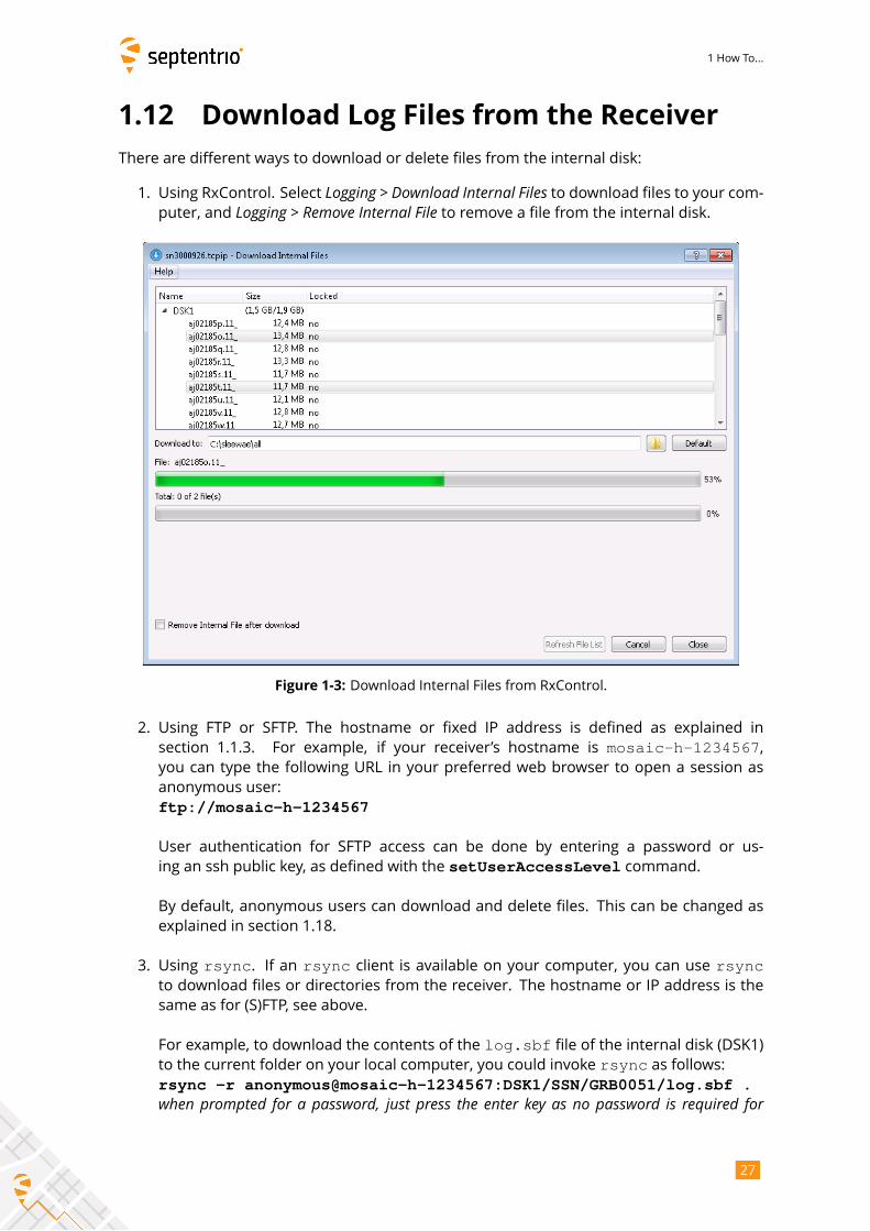
1. Using RxControl. Select Logging > Download Internal Files to download files to your com-puter, and Logging > Remove Internal File to remove a file from the internal disk.
Figure 1-3: Download Internal Files from RxControl.
2. Using FTP or SFTP. The hostname or fixed IP address is defined as explained in
section 1.1.3. For example, if your receiver’s hostname is mosaic-h-1234567,you can type the following URL in your preferred web browser to open a session as
anonymous user:
ftp://mosaic-h-1234567
User authentication for SFTP access can be done by entering a password or us-
ing an ssh public key, as defined with the setUserAccessLevel command.
By default, anonymous users can download and delete files. This can be changed as
explained in section 1.18.
3. Using rsync. If an rsync client is available on your computer, you can use rsyncto download files or directories from the receiver. The hostname or IP address is the
same as for (S)FTP, see above.
For example, to download the contents of the log.sbf file of the internal disk (DSK1)to the current folder on your local computer, you could invoke rsync as follows:rsync -r anonymous@mosaic-h-1234567:DSK1/SSN/GRB0051/log.sbf .when prompted for a password, just press the enter key as no password is required for
27

1 How To...
anonymous accesses.If the same command is issued again at a later stage, rsync will only transfer thedeltas with respect to the files already present on the local machine, significantly
reducing the number of bytes sent compared to retransmitting the entire files.
User authentication can be done by entering a password, or using an ssh public key,
as defined with the setUserAccessLevel command.
By default, rsync is enabled for anonymous users. This can be changed with thesetDefaultAccessLevel command.
4. Using the web interface (select the Logging tab).
28
1 How To...
1.13 FTP Push Log files
It is possible to configure the receiver to automatically send internally-logged files to a re-
mote FTP server (FTP Push). This is done with the setFTPPushSBF and setFTPPushRINEXcommands respectively.
For example, to automatically FTP RINEX files to the directory mydata/rin/YYDDD (withYY and DDD the year and day-of-year) on the remote server myftp.com, with usernamemyname and password mypwd, you would enter the following command:setFTPPushRINEX, myftp.com, mydata/rin/%y%j, myname, mypwd <CR>
To FTP push SBF files to the same location, you would use:
setFTPPushSBF, myftp.com, mydata/rin/%y%j, myname, mypwd <CR>
FTP push will create the folder on the remote server if it does not exist yet.
29
1 How To...
1.14 Communicate with External Equipment
The receiver can send periodical queries to external equipment (such as a meteo sensor)
connected to one of its serial ports, and log the replies from that sensor. In the following
example, we show how to retrieve meteo data every 10 seconds from a meteo sensor con-
nected to the receiver’s COM2 port.
1. Tell the receiver which command to use to query the external sensor, and the
interval at which this command must be sent to the sensor. For instance, for a
MET3/MET4-compatible sensor, the command *0100P9<CR><LF> queries the meteodata. Assuming you want to get meteo data at a 10-second interval, enter the following
command:
setPeriodicEcho, com2, A:*0100P9%%CR%%LF, sec10 <CR>
2. Enable unformatted ASCII input on COM2 (to receive the replies from the meteo
sensor):
setDataInOut,COM2,ASCIIIn <CR>
The replies from the meteo sensor (containing the temperature, pressure and humidity) are
available in the ASCIIIn SBF block.
You can convert an SBF file containing ASCIIIn SBF blocks to RINEX using the sbf2rinprogram or the SBFConverter graphical tool. To be able to generate a RINEX file, the
output of the meteo sensor must be formatted according to the NMEA XDR sentence.
30
1 How To...
1.15 Generate a "Pulse Per Second" Signal
The receiver is able to generate an x-pulse-per-second (xPPS) signal aligned with either GPS,
Galileo or GLONASS system time, or with UTC, or with the internal receiver time.
By default, the PPS is a positive pulse of which the leading edge is synchronous with the sec-
ond boundaries of the time system selected with the setTimingSystem command. Checkthe Hardware Manual for the voltage and the duration of the pulse.
The command setPPSParameters can be used to synchronize the PPS with UTC, GLONASSor the internal time, or to change the PPS interval and polarity. For instance, to synchronize
the PPS with UTC and have one pulse every ten seconds, use:
setPPSParameters,sec10,,,UTC <CR>
When the PPS output is configured to be synchronized with a GNSS system or with UTC, the
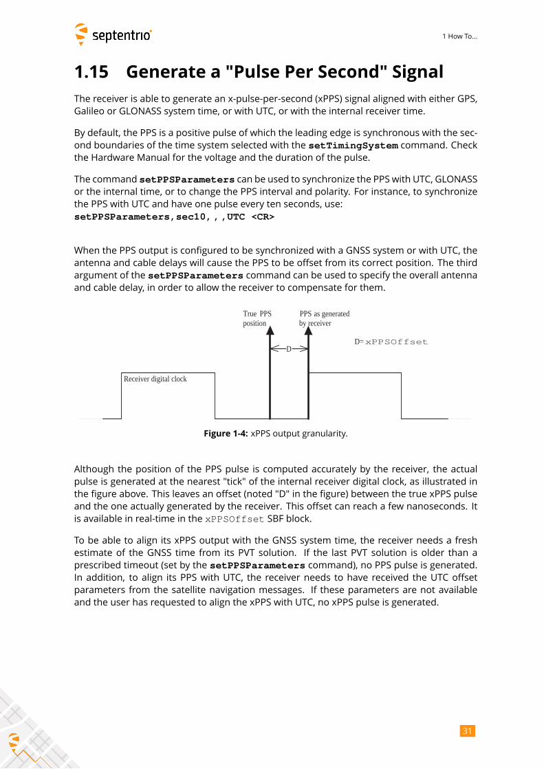
antenna and cable delays will cause the PPS to be offset from its correct position. The third
argument of the setPPSParameters command can be used to specify the overall antennaand cable delay, in order to allow the receiver to compensate for them.
D
True PPS position
PPS as generated by receiver
Receiver digital clock
D= xPPSOffset
Figure 1-4: xPPS output granularity.
Although the position of the PPS pulse is computed accurately by the receiver, the actual
pulse is generated at the nearest "tick" of the internal receiver digital clock, as illustrated in
the figure above. This leaves an offset (noted "D" in the figure) between the true xPPS pulse
and the one actually generated by the receiver. This offset can reach a few nanoseconds. It
is available in real-time in the xPPSOffset SBF block.
To be able to align its xPPS output with the GNSS system time, the receiver needs a fresh
estimate of the GNSS time from its PVT solution. If the last PVT solution is older than a
prescribed timeout (set by the setPPSParameters command), no PPS pulse is generated.In addition, to align its PPS with UTC, the receiver needs to have received the UTC offset
parameters from the satellite navigation messages. If these parameters are not available
and the user has requested to align the xPPS with UTC, no xPPS pulse is generated.
31

1 How To...
1.16 Time Tag External Events
The receiver can time-tag electrical level transitions on its EventX inputs with an accuracy of20ns.
By default, the receiver reacts on low-to-high transitions. You can use the
setEventParameters command to react on falling edges instead:setEventParameters,EventA,High2Low <CR>
Upon detection of a transition, the receiver can output the time and/or the position at the
instant of the event (see for example the ExtEvent SBF block).
The following constraints must be observed to ensure proper event detection:
• There must be no more than 20 events in any interval of 100 milliseconds, all event
pins considered.
• The minimum time between two events on the same EventX input must be at least5ms.
Missed events are flagged by the MISSEDEVENT bit in the ReceiverStatus SBF block.
32
1 How To...
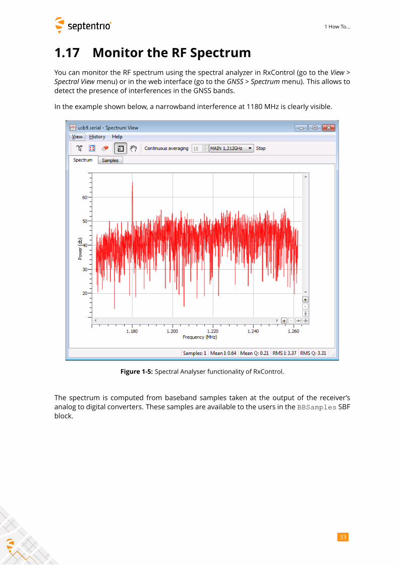
1.17 Monitor the RF Spectrum
You can monitor the RF spectrum using the spectral analyzer in RxControl (go to the View >Spectral View menu) or in the web interface (go to the GNSS > Spectrummenu). This allows todetect the presence of interferences in the GNSS bands.
In the example shown below, a narrowband interference at 1180 MHz is clearly visible.
Figure 1-5: Spectral Analyser functionality of RxControl.
The spectrum is computed from baseband samples taken at the output of the receiver’s
analog to digital converters. These samples are available to the users in the BBSamples SBFblock.
33
1 How To...
1.18 Manage Users
When connecting to the receiver, users can remain "anonymous", or can log in using
the login command. What anonymous users can do depends on the connection type.By default, anonymous users have full control of the receiver. This default configura-
tion can be changed with the setDefaultAccessLevel command. For example, toprevent anonymous access to the web interface and to the FTP server, you would use:
setDefaultAccessLevel, none, none <CR>
To perform actions not allowed to anonymous users, you first need to authenticate your-
self by entering a user name and a password through the login command. The listof user names and passwords and their respective access level is managed with the
setUserAccessLevel command. Login fails if the provided user name or password isnot in that list.
Logged-in users are granted one of the following access levels: "User" or "Viewer". The"User" level allows full control of the receiver, while the "Viewer" level only allows to viewthe configuration.
The following explains how to add or delete a user.
1. Check the current user list by entering the following command:
getUserAccessLevel <CR>The reply to this command looks like:
UserAccessLevel, User1, "admin", "R46NCG", UserUserAccessLevel, User2, "", "", ViewerUserAccessLevel, User3, "", "", Viewer...
2. In the example shown above, only one user is defined: User1 with user name admin.For security reasons, the password shown here (R46NCG) is random and does not cor-respond to the actual password. It can be seen that the level of access of the adminuser is "User": that particular user has full control of the receiver.To add a new user "john" with password "abc123" and to give full access to that user,select a free user index, e.g. User2 in the above example, and type:setUserAccessLevel,User2,john,abc123,User <CR>
3. You can add up to eight users in this way. Deleting a user involves entering an empty
string ("") as user name and password. For example, to delete the "admin" user fromthe above list, use:
setUserAccessLevel,User1,"","" <CR>
The user list also applies to FTP, SFTP and rsync accesses. Users having the "User" accessright are allowed to delete files from the internal disk via FTP, SFTP or rsync, while "Viewer"users can only download files.
34
1 How To...
1.19 Upgrade the Receiver
Upgrading the receiver is the process of installing a new GNSS firmware, a new permission
file (see section 1.21) or a new antenna calibration file (see section 2.5).
In some cases, upgrading the GNSS firmware can clear the receiver configuration stored in
non-volatile memory (see section 1.4). It is therefore advised to recheck the configuration
after the upgrade.
Do not switch power off during the upgrade procedure.
Upgrading the receiver over a serial port can be very slow and it is recommended to upgrade
using a faster connection whenever possible (USB or Ethernet).
Septentrio upgrade files have the extension “.suf”. There are several ways to upgrade the
receiver:
1. By double clicking the “.suf” file. This should launch the RxUpgrade program.
2. By using the RxControl graphical interface (go to the Filemenu).3. From the web interface (go to Admin >Upgrade). This requires to log in as a user withthe "User" access level (see section 1.18).
4. By commanding the receiver to upgrade itself by fetching the upgrade file from a re-
mote FTP server. This is done with the command exeFTPUpgrade.5. By manually downloading upgrade files to the receiver. This upgrade procedure is
explained below.
To manually upgrade the receiver, follow this procedure:
1. Reset the receiver into upgrade mode by entering the following command:
exeResetReceiver, Upgrade, none <CR>
2. Wait till the receiver outputs the string: “Ready for SUF download ...”. From that
moment on, the receiver is waiting for an upgrade file to be downloaded. The file
download must start within 200 seconds, otherwise the receiver will restart in normal
mode.
3. Download the upgrade file to the receiver. Any of the receiver connections can be
used. Make sure to send the file in binary mode, i.e. without changing its contents.
During the download, the receiver outputs a progress indicator at regular interval.
4. At the end of the download, the receiver automatically executes the upgrade instruc-
tions and restarts with the new firmware version. You can check the firmware version
by entering the following command:
lif,Identification <CR>
Before executing the upgrade instructions, the receiver checks the integrity of the down-
loaded file. If the file is corrupted, or is not a valid upgrade file, the receiver discards it and
restarts in normal mode.
If the download is interrupted for any reason, the receiver will restart in normal mode after
a timeout period of 200 seconds.
35
1 How To...
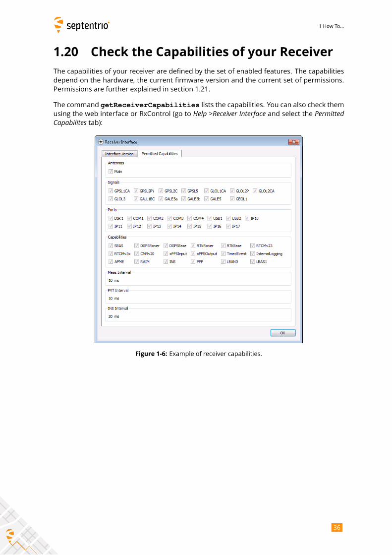
1.20 Check the Capabilities of your Receiver
The capabilities of your receiver are defined by the set of enabled features. The capabilities
depend on the hardware, the current firmware version and the current set of permissions.
Permissions are further explained in section 1.21.
The command getReceiverCapabilities lists the capabilities. You can also check themusing the web interface or RxControl (go to Help >Receiver Interface and select the PermittedCapabilites tab):
Figure 1-6: Example of receiver capabilities.
36
1 How To...
1.21 Check or Change the Permission File
The permission file lists which optional features (such as GLONASS, Galileo, RTK, ...) are
permitted on your receiver, for how long they are permitted and in which region they are
permitted.
The permission file is stored in the receiver’s non-volatile memory, and can be checked with
the command lstInternalFile, Permissions, or with RxControl by clicking Help >Re-ceiver Permissions.Note that, for a given feature to be enabled in the receiver, it must be permitted and the
hardware and firmware version must support it. See also section 1.20.
Each receiver is delivered with a permission file applicable to that receiver only. To enable
new options, the user can order a new permission file to Septentrio, and install it on his/her
receiver using the standard upgrade procedure (see section 1.19).
37

2 Operation Details
Chapter 2
Operation Details
This chapter describes the key processes implemented in the receiver and explains how they
can be configured.
2.1 Channel Allocation and Signal Selection
The receiver automatically allocates satellites to tracking channels up to the limit of the num-
ber of channels. It is possible to override this automatic channel allocation by forcing a
satellite to a given channel with the setChannelAllocation command. Also, a subsetof satellites or a whole constellation can be disabled with the setSatelliteTrackingcommand.
For each satellite, the receiver tries to track all signal types enabled with the
setSignalTracking command. For example, if that command enables the GPSL1CA,GPSL2PY and GLOL1CA signals, GPS satellites will be tracked in dual-frequency mode
(GPSL1CA and GPSL2PY) and GLONASS satellites will be tracked in single-frequency mode
(GLOL1CA only). It is a good practice to only enable those signal types that are needed for
your application to avoid wasting tracking channels.
2.2 Generation of Measurements
For each tracked GNSS signal, the receiver generates a "measurement set", mainly consisting
of the following observables:
• a pseudorange in meters;
• a carrier phase in cycles;
• a Doppler in Hertz;
• a carrier-to-noise ratio in dB-Hz.
All data in a measurement set, and all measurement sets are taken at the same time, which
is referred to as the "measurement epoch". All the measurement sets taken at a given mea-
surement epoch are output in a MeasEpoch SBF block.
Several commands affect the way the receiver produces and outputs measurements:
38
2 Operation Details
• The setHealthMask command can be used to filter out measurements from un-
healthy satellites: these measurements will not be used by the PVT algorithm, nor will
they be included in the MeasEpoch SBF block.• To further reduce the codemeasurement noise, the receiver can be ordered to smooth
the pseudorange by the carrier phase. This technique, sometimes referred to as a
"Hatch filtering", allows to reduce the pseudorange noise andmultipath. It is controlled
by the setSmoothingInterval command and is disabled by default.• The setMultipathMitigation command can be used to enable or disable the mit-igation of multipath errors on the pseudorange and carrier phase measurements. It is
enabled by default.
For advanced applications or in-depth signal analysis, the MeasExtra SBF block containsvarious additional data complementing the MeasEpoch SBF block. Among other things, thisblock reports the multipath correction applied to the pseudorange (allowing one to recom-
pute the original pseudorange), and the observable variances.
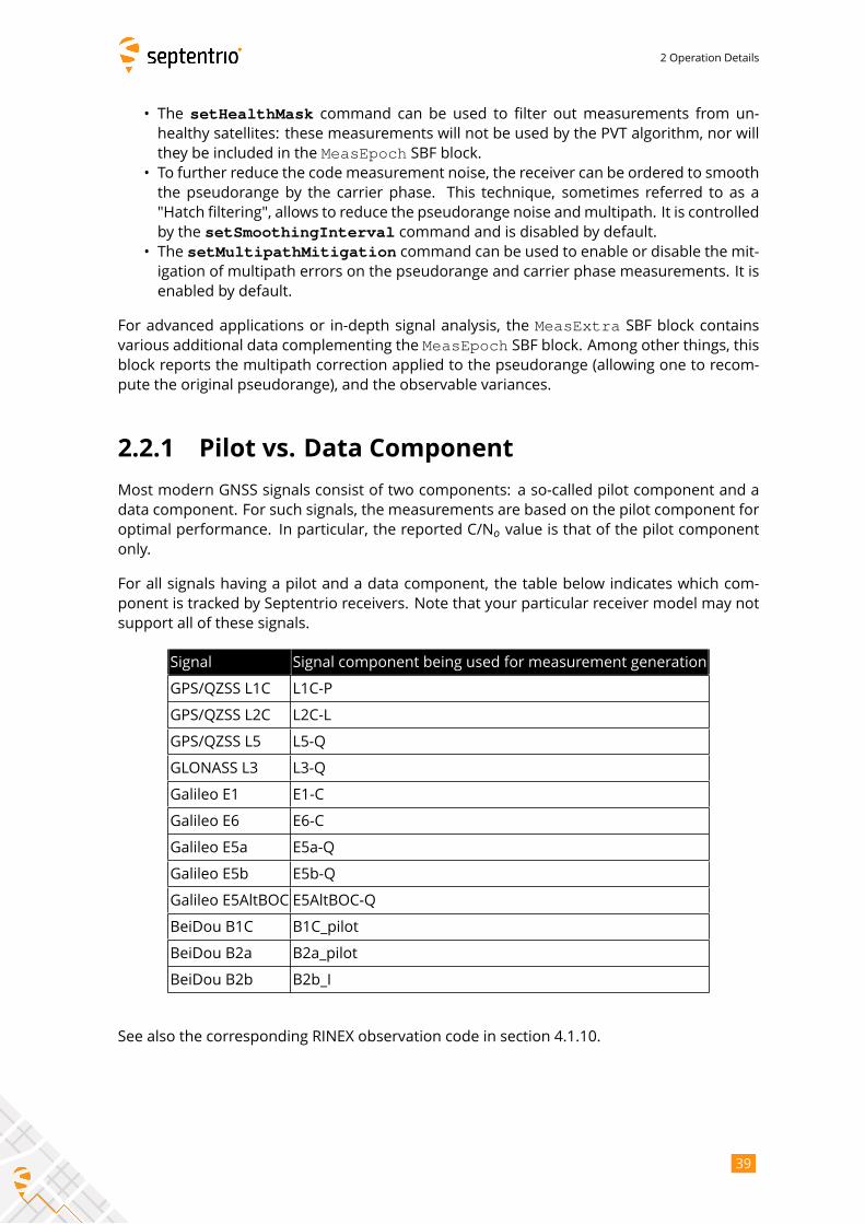
2.2.1 Pilot vs. Data Component
Most modern GNSS signals consist of two components: a so-called pilot component and a
data component. For such signals, the measurements are based on the pilot component for
optimal performance. In particular, the reported C/No value is that of the pilot componentonly.
For all signals having a pilot and a data component, the table below indicates which com-
ponent is tracked by Septentrio receivers. Note that your particular receiver model may not
support all of these signals.
Signal Signal component being used for measurement generation
GPS/QZSS L1C L1C-P
GPS/QZSS L2C L2C-L
GPS/QZSS L5 L5-Q
GLONASS L3 L3-Q
Galileo E1 E1-C
Galileo E6 E6-C
Galileo E5a E5a-Q
Galileo E5b E5b-Q
Galileo E5AltBOC E5AltBOC-Q
BeiDou B1C B1C_pilot
BeiDou B2a B2a_pilot
BeiDou B2b B2b_I
See also the corresponding RINEX observation code in section 4.1.10.
39
2 Operation Details
2.3 Time Management
All time tags in the receiver refer to the receiver time scale. The receiver is designed in such a
way that the receiver time is kept as close as possible to the selected GNSS system time (GPS
or Galileo as prescribed by the setTimingSystem command). Internally, the receiver timeis kept in two counters: the time-of-week counter in integer milliseconds (TOW) and the week
number counter (WNc). WNc counts the number of complete weeks elapsed since January
6, 1980 (even if the selected GNSS system time is not GPS). The TOW and WNc counters are
reported in all SBF blocks.
The synchronization of TOW and WNc with the GNSS system time involves the following
steps:
• Upon powering up the receiver, TOW and WNc are assumed unknown, and set to a
"Do-Not-Use value" in the SBF blocks.
• The transmission time-of-week and week number are decoded from the GNSS satel-
lites:
– As soon as the first time-of-week is decoded from the satellites, the TOW counter
is initialized to within 20 ms of GNSS system time and starts counting. This is also
the time when the receiver starts generating GNSS measurements (pseudoranges
and carrier phases).
– As soon as the week number is decoded from the satellites (which can be either
simultaneously with the time-of-week, or several seconds later), the WNc counter
is set and starts counting.
• After the first position and time fix has been computed (for which measurements from
at least 4 satellites are required), TOW is set to within X milliseconds of GNSS time.
This is done by introducing a jump of an integer number of milliseconds in the TOW
counter. X is the maximal allowed offset between the receiver time and GNSS time,
and is set by the setClockSyncThreshold command (by default, X=0.5ms). Thisinitial clock synchronization leads to a simultaneous jump in all the pseudorange and
carrier phase measurements.
The level to which the receiver time is synchronized with the GNSS system time is given by
three status bits (TOWSET, WNSET and FINETIME) available both in the ReceiverTime SBFblock and the ReceiverStatus SBF block.
The receiver clock can be configured in free-running mode, or in steered mode using the
command setClockSyncThreshold.
2.3.1 Free-Running Clock
In free-running mode, the receiver time slowly drifts with respect to GNSS time. The re-
ceiver continuously monitors this time offset: this is the clock bias term computed in the PVT
solution, as provided in the RxClkBias field of the PVTCartesian and PVTGeodeticSBF blocks. A clock jump of an integer number of milliseconds is imposed on the re-
ceiver clock each time the clock bias exceeds X milliseconds by an absolute value (X is set
by setClockSyncThreshold). This typically results in a saw-tooth profile similar to thatshown in Figure 2-1. In this example, X=0.5ms and each time the clock bias becomes greater
than 0.5ms, a jump of 1ms is applied.
40
2 Operation Details
0 0.5 1 1.5 2 2.5 3 3.5 4−0.5
0
0.5
Up Time [hours]
RxC
lkB
ias
= t R
x−t G
NS
S [m
s]
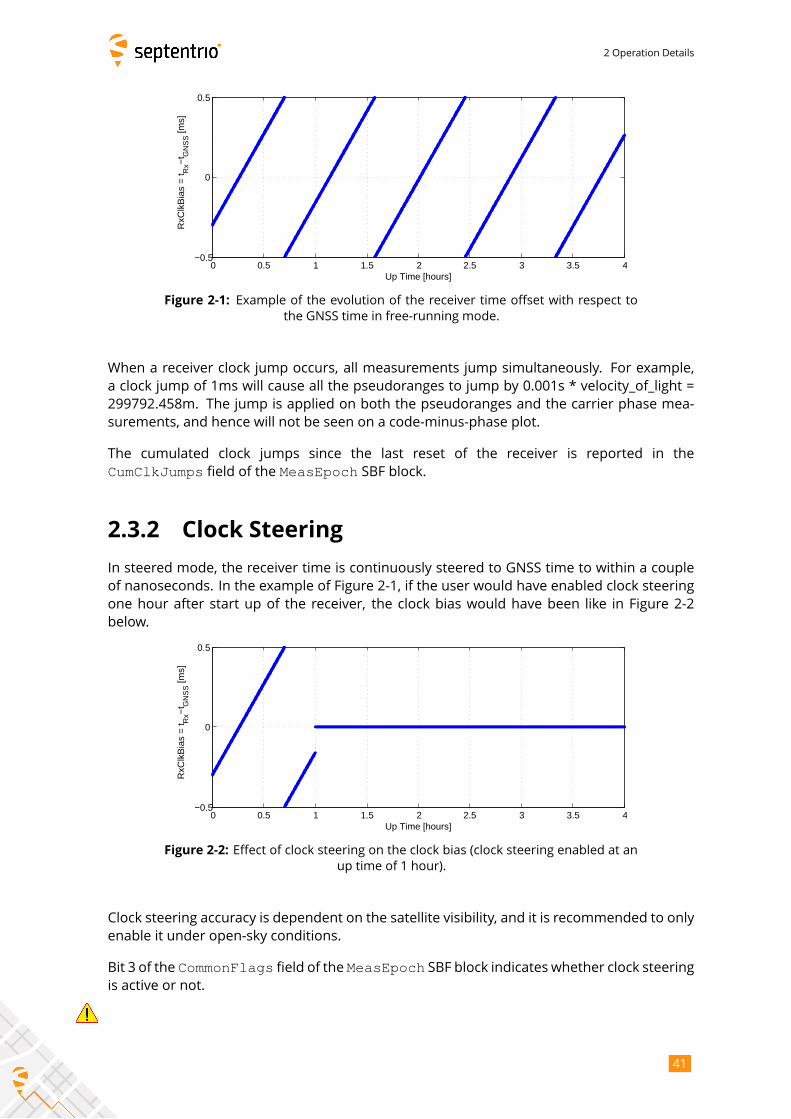
Figure 2-1: Example of the evolution of the receiver time offset with respect to
the GNSS time in free-running mode.
When a receiver clock jump occurs, all measurements jump simultaneously. For example,
a clock jump of 1ms will cause all the pseudoranges to jump by 0.001s * velocity_of_light =
299792.458m. The jump is applied on both the pseudoranges and the carrier phase mea-
surements, and hence will not be seen on a code-minus-phase plot.
The cumulated clock jumps since the last reset of the receiver is reported in the
CumClkJumps field of the MeasEpoch SBF block.
2.3.2 Clock Steering
In steered mode, the receiver time is continuously steered to GNSS time to within a couple
of nanoseconds. In the example of Figure 2-1, if the user would have enabled clock steering
one hour after start up of the receiver, the clock bias would have been like in Figure 2-2
below.
0 0.5 1 1.5 2 2.5 3 3.5 4−0.5
0
0.5
Up Time [hours]
RxC
lkB
ias
= t R
x−t G
NS
S [m
s]
Figure 2-2: Effect of clock steering on the clock bias (clock steering enabled at an
up time of 1 hour).
Clock steering accuracy is dependent on the satellite visibility, and it is recommended to only
enable it under open-sky conditions.
Bit 3 of the CommonFlags field of the MeasEpoch SBF block indicates whether clock steeringis active or not.
41

2 Operation Details
Note for the users of a GNSS constellation simulator:
When using a constellation simulator, make sure to set the simulation time after January 01,
2016. The receiver time will be incorrect before that date.
For correct time determination, it is mandatory to reset the receiver before every (re)start of
the simulation.
2.4 Computation of Position, Velocity, and
Time (PVT Solution)
The receiver computes the position, velocity and time (PVT) based on the pseudoranges, the
Doppler measurements and, if applicable, the differential corrections.
The availability of the PVT depends on:
• the number of available pseudoranges and Doppler measurements, equal to the num-
ber of tracked satellites, or a subset of them as specified by the setSatelliteUsagecommand;
• the number of valid sets of broadcast ephemerides, which are needed to compute the
position, velocity, and clock bias for each tracked satellite;
• the number of valid sets of fast and long-term SBAS corrections and their age in the
case of SBAS-aided positioning;
• the number of valid differential corrections and their age in the case of DGPS/RTK po-
sitioning.
A position fix requires a minimum of 4 tracked satellites with associated ephemerides. When
a PVT solution is not available, PVT-related SBF blocks are still output with all the numeric
fields set to Do-Not-Use values, and with the Error field set to indicate the source of the
problem.
The accuracy of the PVT depends on:
• The signal level.
• The geometry of the satellite constellation expressed in the DOP values: these values
indicate the ratio of positional errors to range errors and are computed on the basis
of the error propagation theory. When the DOP is high, the accuracy of positioning will
be low.
• The number of available satellites: the more satellites are available, the lower the DOP.
Measurement redundancy also enables better outlier detection.
• Multipath errors on the pseudorange measurements: multipath errors can
be largely attenuated by enabling the APME multipath mitigation method
(see setMultipathMitigation) and/or using code smoothing (see
setSmoothingInterval).• The PVT mode as set by the setPVTMode command.• The data available to compute ionospheric delays (see setIonosphereModel).• The choice of the dynamics model: if the dynamics parameter set by the
setReceiverDynamics command does not correspond to the actual dynamics ofthe receiver platform, the position estimation will be sub-optimal.
42
2 Operation Details
The a-posteriori accuracy estimate of the computed position is reported in the variance-
covariance matrix, which comes in the PosCovCartesian and PosCovGeodetic SBFblocks. This accuracy estimate is based on the assumed measurement noise model and
may differ from actual errors due to many external factors, most of all multipath.
2.4.1 SBAS Positioning
SBAS, which stands for ’Space Based Augmentation System’, enables differential operation
over a large area with associated integrity information. System errors are computed from a
dataset recorded over a continental area and disseminated via a geostationary satellite. The
operation of SBAS is documented in the RTCA DO 229 standard. SBAS improves over DGPS
corrections, in that it provides system corrections (ionosphere corrections and ephemeris
long-term corrections) next to range corrections (the "fast corrections" in the DO 229 termi-
nology).
The receiver provides an SBAS-aided position when it has sufficient satellites with at least
fast and long-term corrections. The corrections are used as long as their applicability has
not timed out. During the time-out interval the receiver applies correction degradation using
the information received in message type (MT) 07 and 10.
By default, the receiver selects the SBAS satellite with the most SBAS corrections available.
With the setSBASCorrections command, it is possible to force the receiver to use a par-ticular SBAS satellite or a particular SBAS provider.
2.4.2 DGPS Positioning
DGPS (Differential GPS) is a pseudorange-based positioning technique where GNSS system
errors are reduced by the use of range corrections. To work in DGPS rover mode, the receiver
needs to receive differential corrections in the RTCM or CMR format.
Note on the RTCM v2.x corrections: the receiver takes the τgd parameter transmitted bythe GPS satellites into account during the computation of the pseudorange corrections, as
prescribed in v2.2 and v2.3 of the RTCM standard. The RTCM standard version 2.1 is ambigu-
ous in this respect: it does neither prescribe nor discourage the use of τgd. The receiver canbe configured in both modes using the command setRTCMv2Compatibility.
2.4.3 RTK Positioning
Real-Time Kinematic (RTK) is a carrier phase positioning method where the carrier phase
ambiguities are estimated in a kinematic mode.
To work in RTK mode, the receiver requires the reception of RTK messages. Both the RTCM
and the CMR message formats are supported. Multiple-base RTK is not supported: by de-
fault, the receiver selects the nearest base station if more than one base station is available.
In RTK mode, the absolute position is reported in the PVTCartesian or PVTGeodetic SBFblocks, and the baseline vector is reported in the BaseVectorCart and BaseVectorGeodSBF blocks.
43
2 Operation Details
2.4.3.1 Integer Ambiguities (RTK-fixed)
The key to high-accuracy carrier phase positioning is the fixing of the carrier phase integer
ambiguities. Under normal circumstances the receiver will compute the integer ambiguities
within several seconds and yield an RTK-fixed solution with centimeter-level accuracy. The
less accurate pseudorange measurements will not be used. As long as no cycle slips or loss-
of-lock events occurs, the carrier phase position is readily available.
RTK with fixed ambiguities is also commonly referred to as phase positioning using ’On-The-
Fly’ (OTF) ambiguity fixing. The RTK positioning engine of the receiver uses the LAMBDA
method(1)developed at Delft University, department of Geodesy.
2.4.3.2 Floating Ambiguities (RTK-float)
When data availability is low (e.g. low number of satellites) or when the data are not of suf-
ficient quality (high multipath), the receiver will not fix the carrier phase ambiguities to their
integer value, but will keep them floating. At the start of the RTK-float convergence process,
the position accuracy is equal to that of code-based DGPS. Over the course of several min-
utes the positional accuracy will converge from several decimeters to several centimeters as
the floating ambiguities become more accurate.
2.4.4 Transition between PVT Modes
Whenever possible, the transitions from a more accurate PVT mode to a less accurate PVT
mode are smooth. For example, when switching from RTK to DGPS mode, the position does
not exhibit a sudden jump, but slowly degrades from RTK to DGPS accuracy.
2.4.5 Datum Transformation
By default the datum to which the coordinates refer depends on the positioning mode.
For standalone and SBAS positioning for example, the coordinates refer to a global datum:
WGS84 or ITRS. When using DGPS or RTK corrections from a DGPS/RTK provider, the coordi-
nates usually refer to a regional datum (e.g. ETRS89 in Europe).
Recent realisations of WGS84 and ITRS are closely aligned and the difference can be ne-
glected in most cases. The receiver considers them equivalent. However, regional datums
may significantly differ from WGS84/ITRS, which may lead to coordinate jumps when switch-
ing between different positioning modes.
2.4.5.1 Transformation to Regional Datum
It is possible to avoid this datum shift by configuring the receiver to transform all co-
ordinates to the regional datum used by the RTK base stations. This is done with the
(1)Teunissen, P.J.G., and C.C.J.M. Tiberius (1994) Integer least-squares estimation of the GPS phase ambiguities.
Proceedings of International Symposium on Kinematic Systems in Geodesy, Geomatics and Navigation KIS’94,
Banff, Canada, August 30-September 2, pp. 221-231.
44
2 Operation Details
setGeodeticDatum command. The receiver knows the transformation parameters ap-plicable to the most common datums (e.g. ETRS89 or NAD83), but user datums can also be
defined with the setUserDatum command.
Coordinates in the PVTCartesian and PVTGeodetic SBF blocks refer to the datum se-lected in setGeodeticDatum. The datum can be checked by decoding the Datum field of
these blocks.
2.4.5.2 Transformation to Local Datum
Sometimes it is needed to relate the coordinates to a local datum. Some RTK networks pro-
vide the necessary transformation and projection parameters as part of their RTCM stream,
in message types 1021 to 1027.
The local geodetic coordinates (latitude, longitude and height) are reported in the PosLocalSBF block, and the plane grid coordinates (easting, northing, height) are reported in the
PosProjected SBF block.
The following conditions must be met for the receiver to provide local coordinates from the
information sent by the RTK network:
• the usage of RTCM v3.x MT1021-1027 must be enabled by the command
setRTCMv3Usage (these messages are enabled by default).• the local coordinate operations must be set to NETWORK with the
setLocalCoordOperation command (this is the default).• the complete set of datum transformation messages must have been received from
the network. Plane grid coordinates are only available if the network supports one of
the messages in the 1025-1027 range. Otherwise, only the local latitude, longitude and
height are available.
• the position must be in the area of validity of the transformation parameters.
• to continue to get unbiased local coordinates when the positioning mode is not DGPS
or RTK, the network regional datum must be set with the setGeodeticDatum com-mand. See section 2.4.5.1.
A number of local datum transformations are preloaded in the receiver (the list can be re-
trieved with the lstLocalCoordOperations command). If your local datum belongs tothis list, local coordinates can be computed without information from the RTK network. See
the setLocalCoordOperation command for details.
2.5 Antenna Effects
To achieve the highest positioning precision, it is essential to take antenna effects into ac-
count.
45

2 Operation Details
PC
ARP
Marker
Figure 2-3: Antenna mount.
The GNSS measurements (pseudoranges and carrier phases observables) refer to a theoret-
ical point in space called the phase center (noted PC in Figure 2-3). The position of this point
is dependent on the elevation of the satellite and on the frequency band. It varies with time
and it is different for the different GNSS frequency bands. The phase center variation can
reach a few centimeters.
If no correction is applied, the computed position refers to an average phase center with no
easy link with the antenna physical element. This average phase center fluctuates with time
and cannot be used for accurate millimeter-level positioning.
For high-precision positioning, the GNSS measurements need to be corrected in such a way
that they all refer to a common and stable point in space. That point is referred to as the
antenna reference point (ARP). For convenience, it is usually selected at the center of the
bottom surface of the antenna. PC to ARP calibration tables are available on Internet for a
large number of geodetic-grade antennas. For example, the National Geodetic Survey (NGS)
publishes calibration tables that can be downloaded from the following URL:
https://www.ngs.noaa.gov/ANTCAL/.The antenna naming convention in such table is the one adopted by the IGS Central Bureau.
The receiver has a similar table in its non-volatile memory. This table can be upgraded follow-
ing the standard upgrade procedure as described in section 1.19 (the upgrade file is named
ant_info.suf).
2.5.1 Antenna Effects in Rover Mode
If the user specifies the type of his/her antenna using the setAntennaOffset command,the receiver compensates for the phase center variation in all rover positioning modes. If the
antenna is not specified, or the antenna type is not present in the built-in antenna calibration
file, the receiver cannotmake the distinction between phase center and ARP, and the position
accuracy is slightly degraded, especially in the height component.
The point to be positioned is the "marker" (see Figure 2-3). The offset between the ARP and
the marker is a function of the antenna monumentation. It must be measured by the user
and specified with the setAntennaOffset command.
46

2 Operation Details
The absolute position reported in the PVTCartesian and PVTGeodetic SBF blocks is al-ways the marker position.
In DGPS or RTK modes, the receiver needs to know the type of antenna used at the base
station in order to properly compensate for the phase center variation at the base. This
information is typically included in the correction stream received from the base station.
The base-to-rover baseline coordinates in the BaseVectorCart and BaseVectorGeodSBF blocks is from ARP to ARP unless the receiver is not able to properly compensate for the
phase center variation at base or rover. Refer to the description of the BaseVectorCartSBF blocks for details.
47

3 Command Line Reference
Chapter 3
Command Line Reference
48
3 Command Line Reference
3.1 Command Line Interface Outline
The receiver outputs a prompt when it is ready to accept a user command. The prompt is of
the form:
CD>
where CD is the connection descriptor of the current connection, e.g. COM1 (see sec-tion1.1.5).
The prompt indicates the termination of the processing of a given command. When sending
multiple commands to the receiver, it is necessary to wait for the prompt between each
command.
Sometimes a connection is not configured to accept user commands, for example because
it is put into differential correction input mode. A way to force a connection to accept com-
mands is to send a succession of ten “S” characters to that connection and then to press the
enter key (SSSSSSSSSS<CR>). See also the description of the setDataInOut command.
3.1.1 Command Types
Most commands fall into one of the following categories:
set-commands to change one or more configuration parameters;get-commands to get the current value of one or more configuration parameters;exe-commands to initiate some action;lst-commands to retrieve the contents of internal files or list the commands.
Each set-command has its get-counterpart, but the opposite is not true. For in-
stance, the setNMEAOutput command has a corresponding getNMEAOutput, butgetReceiverCapabilities has no set-counterpart. Each exe-command also has itsget-counterpart which can be used to retrieve the parameters of the last invocation of thecommand.
3.1.2 Command Line Syntax
Each ASCII command line consists of a command name optionally followed by a list of ar-
guments and terminated by <CR>, <LF> or <CR><LF> character(s) usually corresponding to
pressing the "Enter" key on the keyboard.
To minimize typing effort when sending commands by hand, the command name can
be replaced by its 3-5 character mnemonic. For instance, grc can be used instead ofgetReceiverCapabilities.
The receiver is case insensitive when interpreting a command line.
49
3 Command Line Reference
The maximum length of any ASCII command line is 2000 characters.
For commands requiring arguments, the comma "," must be used to separate the arguments
from each other and from the command’s name. Any number of spaces can be inserted
before and after the comma.
Each argument of a set-command corresponds to a single configuration parameter in thereceiver. Usually, each of these configuration parameters can be set independently of the
others, so most of the set-command’s arguments are optional. Optional arguments canbe omitted but if omitted arguments are followed by non-omitted ones, a corresponding
number of commas must be entered. Omitted arguments always keep their current value.
3.1.3 Command Replies
The reply to ASCII commands always starts with "$R" and ends with <CR><LF> followed by
the prompt corresponding to the connection descriptor you are connected to.
The following types of replies are defined for ASCII commands:
• For comment lines (user input beginning with "#") or empty commands (just pressing
"Enter"), the receiver replies with the prompt.
COM1> # This is a comment! <CR>COM1>
• For invalid commands, the reply is an error message, always beginning with the key-
word "$R?" followed by an error message.
• For all valid set-, get- and exe-commands, the first line of the reply is an exact copyof the command as entered by the user, preceded with "$R:". One or more additional
lines are printed depending on the command. These lines report the configuration of
the receiver after execution of the command.
COM1>setNMEAOutput, stream1, com1, GGA, sec1 <CR>$R: setNMEAOutput, stream1, com1, GGA, sec1NMEAOutput, stream1, com1, GGA, sec1
COM1>
For commands which reset or halt the receiver (e.g. exeResetReceiver), the replyis terminated by "STOP>" instead of the standard prompt, to indicate that no furthercommand can be entered.
• For all valid lst-commands, the first line of the reply is an exact copy of the com-mand as entered by the user, preceded with "$R;". The second line is a pseudo-prompt
"−−−−>" and the remaining of the reply is a succession of formatted blocks, each ofthem starting with "$−− BLOCK".
50
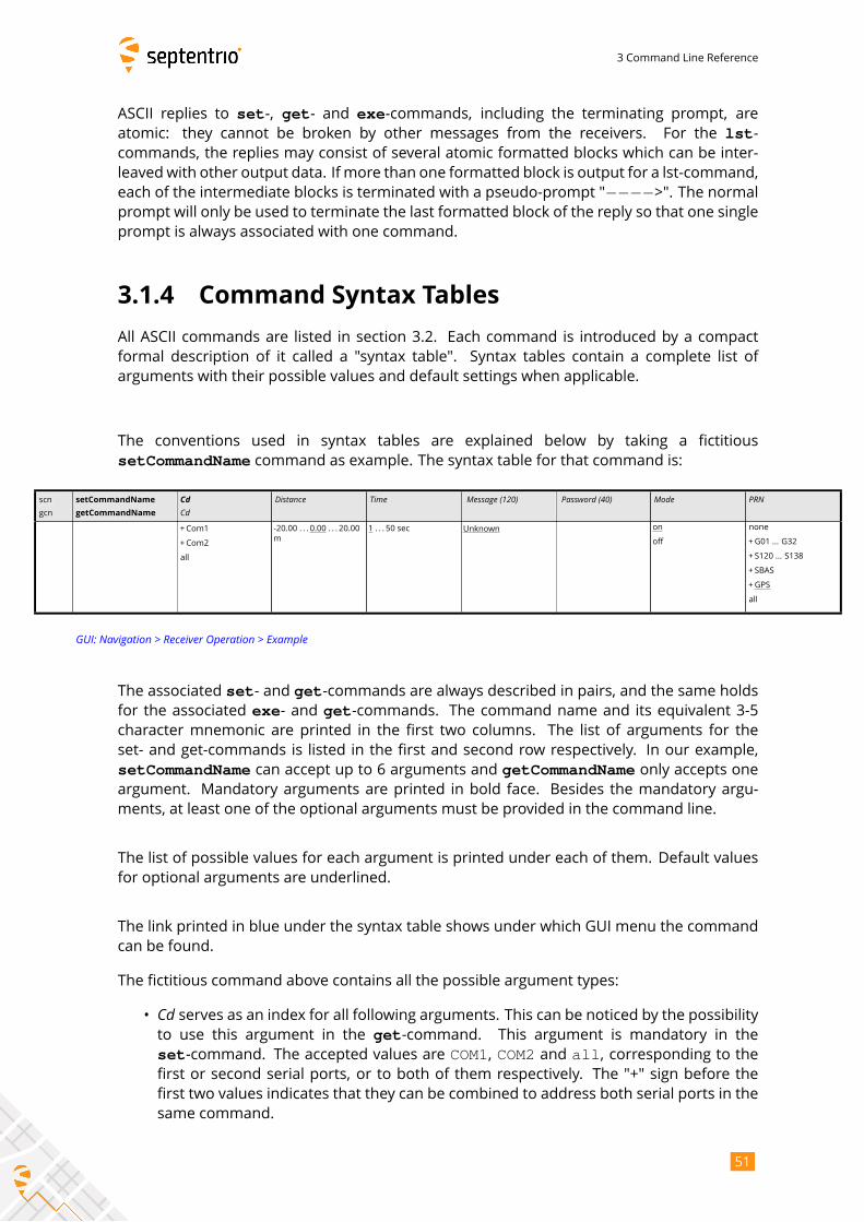
3 Command Line Reference
ASCII replies to set-, get- and exe-commands, including the terminating prompt, areatomic: they cannot be broken by other messages from the receivers. For the lst-commands, the replies may consist of several atomic formatted blocks which can be inter-
leaved with other output data. If more than one formatted block is output for a lst-command,
each of the intermediate blocks is terminated with a pseudo-prompt "−−−−>". The normalprompt will only be used to terminate the last formatted block of the reply so that one single
prompt is always associated with one command.
3.1.4 Command Syntax Tables
All ASCII commands are listed in section 3.2. Each command is introduced by a compact
formal description of it called a "syntax table". Syntax tables contain a complete list of
arguments with their possible values and default settings when applicable.
The conventions used in syntax tables are explained below by taking a fictitious
setCommandName command as example. The syntax table for that command is:
scn
gcn
setCommandName
getCommandName
CdCd
Distance Time Message (120) Password (40) Mode PRN
+Com1
+Com2
all
-20.00 . . . 0.00 . . . 20.00
m
1 . . . 50 sec Unknown on
off
none
+G01 ... G32
+ S120 ... S138
+ SBAS
+GPS
all
GUI: Navigation > Receiver Operation > Example
The associated set- and get-commands are always described in pairs, and the same holdsfor the associated exe- and get-commands. The command name and its equivalent 3-5character mnemonic are printed in the first two columns. The list of arguments for the
set- and get-commands is listed in the first and second row respectively. In our example,
setCommandName can accept up to 6 arguments and getCommandName only accepts oneargument. Mandatory arguments are printed in bold face. Besides the mandatory argu-
ments, at least one of the optional arguments must be provided in the command line.
The list of possible values for each argument is printed under each of them. Default values
for optional arguments are underlined.
The link printed in blue under the syntax table shows under which GUImenu the command
can be found.
The fictitious command above contains all the possible argument types:
• Cd serves as an index for all following arguments. This can be noticed by the possibilityto use this argument in the get-command. This argument is mandatory in the
set-command. The accepted values are COM1, COM2 and all, corresponding to thefirst or second serial ports, or to both of them respectively. The "+" sign before the
first two values indicates that they can be combined to address both serial ports in the
same command.
51
3 Command Line Reference
Examples: COM1, COM1+COM2, all (which is actually an alias for COM1+COM2).
• Distance is a number between -20 and 20 with a default value of 0, and up to 2decimal digits. An error is returned if more digits are provided. The "m" indicates
that the value is expressed in meters. Note that this "m" should not be typed when
entering the command.
Examples: 20, 10.3, -2.34
• Time is a number between 1 and 50, with no decimal digit (i.e. this is an integer value).This value is expressed in seconds.
Examples: 1, 10
• Message is a string with a maximum length of 120 characters. The default value ofthat argument is "Unknown". When spaces must to be used, the string has to be putbetween quotes and these enclosing quotes are not considered part of the string. The
list of allowed characters in strings is:
ABCDEFGHIJKLMNOPQRSTUVWXYZabcdefghijklmnopqrstuvwxyz0123456789!#%@()*+-./:;<=>?[\]^_‘{|}~
Example: "Hello World!"
• Password is a password argument with amaximum length of 20 characters (40/2). Pass-word arguments are always named Password or Key. Only half of the total passwordlength is available to the user, the other half being reserved by the system. Passwords
are obfuscated by the receiver so that they cannot be read back in command replies.
In addition to the characters above (see the Message argument), special characters areallowed in passwords using the corresponding escape sequence:
– Type %%DQ to obtain "– Type %%SQ to obtain ’– Type %%DL to obtain $– Type %%AM to obtain &– Type %%CM to obtain ,
Example: "ab%%AM123"
• Mode is a range of individual values that cannot be combined (they are not precededby a "+" sign). Either off or on can be selected for that argument and the defaultvalue is on.
Example: on
52

3 Command Line Reference
• PRN is a range of values that can be combined together with the "+" sign. The defaultvalue GPS is an alias for G01+G02+ ... +G32, SBAS is an alias for S120+ ...+S138 and all an alias for GPS+SBAS. A "+" sign can be set before the argumentto indicate to add the specified value(s) to the current list. If the value "none" is sup-ported (which is the case in this example), a "-" sign can be set before the argumentto remove the specified value(s) from the current list. It is possible to add or remove
multiple values at once by "adding" or "subtracting" them with the "+" or "-" operator.However, "+" and "-" can never be combined in a single argument.
Examples: G01+G02, +G03, GPS+S120, +G04+G05, -S122-S123, -GPS
53
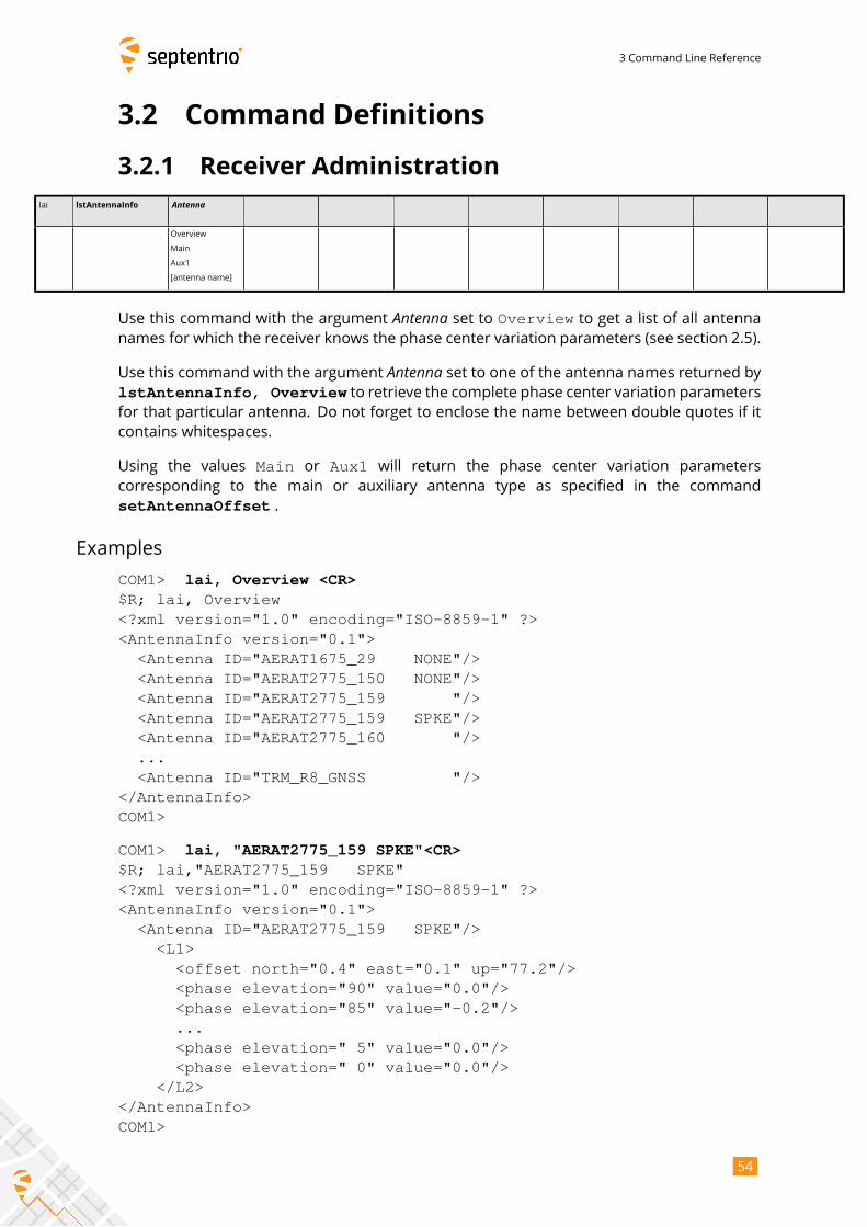
3 Command Line Reference
3.2 Command Definitions
3.2.1 Receiver Administration
lai lstAntennaInfo Antenna
Overview
Main
Aux1
[antenna name]
Use this command with the argument Antenna set to Overview to get a list of all antennanames for which the receiver knows the phase center variation parameters (see section 2.5).
Use this command with the argument Antenna set to one of the antenna names returned bylstAntennaInfo, Overview to retrieve the complete phase center variation parametersfor that particular antenna. Do not forget to enclose the name between double quotes if it
contains whitespaces.
Using the values Main or Aux1 will return the phase center variation parameters
corresponding to the main or auxiliary antenna type as specified in the command
setAntennaOffset .
Examples
COM1> lai, Overview <CR>$R; lai, Overview<?xml version="1.0" encoding="ISO-8859-1" ?><AntennaInfo version="0.1">
<Antenna ID="AERAT1675_29 NONE"/><Antenna ID="AERAT2775_150 NONE"/><Antenna ID="AERAT2775_159 "/><Antenna ID="AERAT2775_159 SPKE"/><Antenna ID="AERAT2775_160 "/>...<Antenna ID="TRM_R8_GNSS "/>
</AntennaInfo>COM1>
COM1> lai, "AERAT2775_159 SPKE"<CR>$R; lai,"AERAT2775_159 SPKE"<?xml version="1.0" encoding="ISO-8859-1" ?><AntennaInfo version="0.1">
<Antenna ID="AERAT2775_159 SPKE"/><L1>
<offset north="0.4" east="0.1" up="77.2"/><phase elevation="90" value="0.0"/><phase elevation="85" value="-0.2"/>...<phase elevation=" 5" value="0.0"/><phase elevation=" 0" value="0.0"/>
</L2></AntennaInfo>COM1>
54
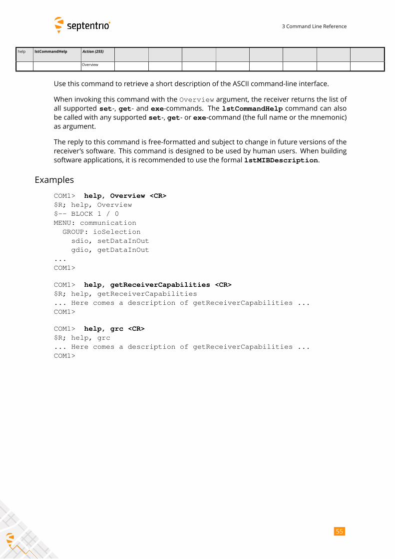
3 Command Line Reference
help lstCommandHelp Action (255)
Overview
Use this command to retrieve a short description of the ASCII command-line interface.
When invoking this command with the Overview argument, the receiver returns the list ofall supported set-, get- and exe-commands. The lstCommandHelp command can alsobe called with any supported set-, get- or exe-command (the full name or the mnemonic)as argument.
The reply to this command is free-formatted and subject to change in future versions of the
receiver’s software. This command is designed to be used by human users. When building
software applications, it is recommended to use the formal lstMIBDescription.
Examples
COM1> help, Overview <CR>$R; help, Overview$-- BLOCK 1 / 0MENU: communication
GROUP: ioSelectionsdio, setDataInOutgdio, getDataInOut
...COM1>
COM1> help, getReceiverCapabilities <CR>$R; help, getReceiverCapabilities... Here comes a description of getReceiverCapabilities ...COM1>
COM1> help, grc <CR>$R; help, grc... Here comes a description of getReceiverCapabilities ...COM1>
55
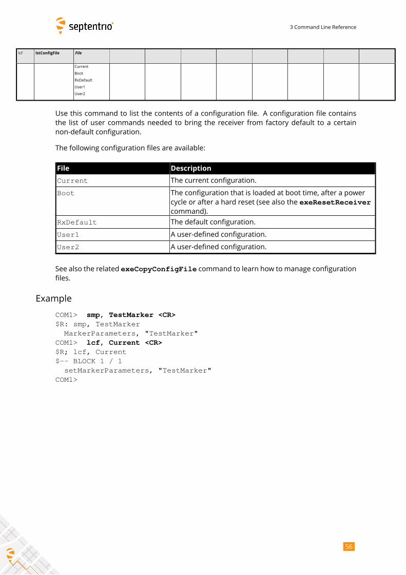
3 Command Line Reference
lcf lstConfigFile File
Current
Boot
RxDefault
User1
User2
Use this command to list the contents of a configuration file. A configuration file contains
the list of user commands needed to bring the receiver from factory default to a certain
non-default configuration.
The following configuration files are available:
File Description
Current The current configuration.
Boot The configuration that is loaded at boot time, after a power
cycle or after a hard reset (see also the exeResetReceivercommand).
RxDefault The default configuration.
User1 A user-defined configuration.
User2 A user-defined configuration.
See also the related exeCopyConfigFile command to learn how to manage configurationfiles.
Example
COM1> smp, TestMarker <CR>$R: smp, TestMarker
MarkerParameters, "TestMarker"COM1> lcf, Current <CR>$R; lcf, Current$-- BLOCK 1 / 1
setMarkerParameters, "TestMarker"COM1>
56
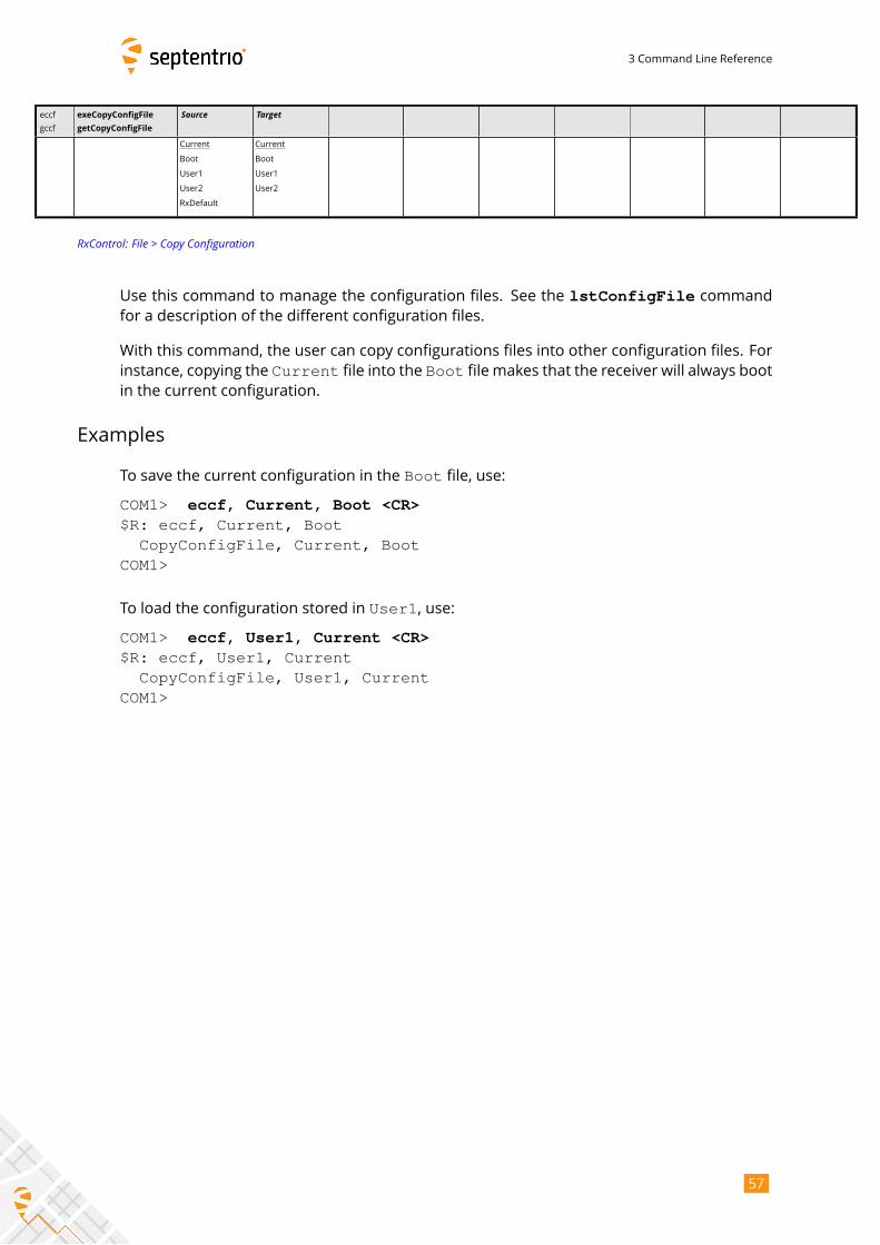
3 Command Line Reference
eccf
gccf
exeCopyConfigFile
getCopyConfigFile
Source Target
Current
Boot
User1
User2
RxDefault
Current
Boot
User1
User2
RxControl: File > Copy Configuration
Use this command to manage the configuration files. See the lstConfigFile commandfor a description of the different configuration files.
With this command, the user can copy configurations files into other configuration files. For
instance, copying the Current file into the Boot file makes that the receiver will always bootin the current configuration.
Examples
To save the current configuration in the Boot file, use:
COM1> eccf, Current, Boot <CR>$R: eccf, Current, Boot
CopyConfigFile, Current, BootCOM1>
To load the configuration stored in User1, use:
COM1> eccf, User1, Current <CR>$R: eccf, User1, Current
CopyConfigFile, User1, CurrentCOM1>
57
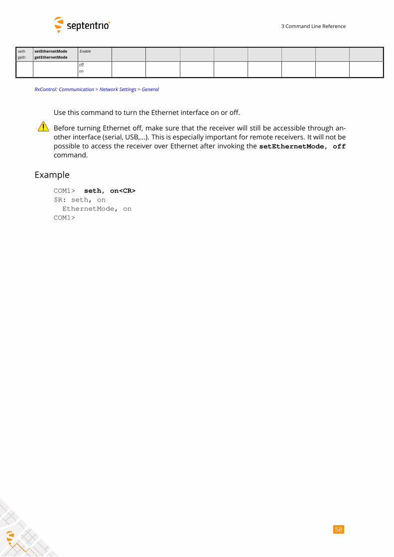
3 Command Line Reference
seth
geth
setEthernetMode
getEthernetMode
Enable
off
on
RxControl: Communication > Network Settings > General
Use this command to turn the Ethernet interface on or off.
Before turning Ethernet off, make sure that the receiver will still be accessible through an-
other interface (serial, USB,...). This is especially important for remote receivers. It will not be
possible to access the receiver over Ethernet after invoking the setEthernetMode, offcommand.
Example
COM1> seth, on<CR>$R: seth, on
EthernetMode, onCOM1>
58
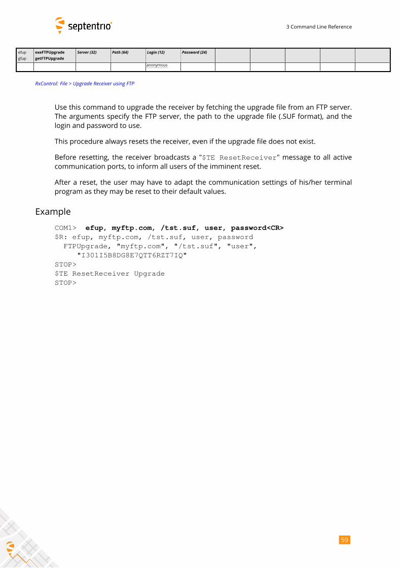
3 Command Line Reference
efup
gfup
exeFTPUpgrade
getFTPUpgrade
Server (32) Path (64) Login (12) Password (24)
anonymous
RxControl: File > Upgrade Receiver using FTP
Use this command to upgrade the receiver by fetching the upgrade file from an FTP server.
The arguments specify the FTP server, the path to the upgrade file (.SUF format), and the
login and password to use.
This procedure always resets the receiver, even if the upgrade file does not exist.
Before resetting, the receiver broadcasts a "$TE ResetReceiver" message to all activecommunication ports, to inform all users of the imminent reset.
After a reset, the user may have to adapt the communication settings of his/her terminal
program as they may be reset to their default values.
Example
COM1> efup, myftp.com, /tst.suf, user, password<CR>$R: efup, myftp.com, /tst.suf, user, password
FTPUpgrade, "myftp.com", "/tst.suf", "user","I301I5B8DG8E7QTT6RZT7IQ"
STOP>$TE ResetReceiver UpgradeSTOP>
59
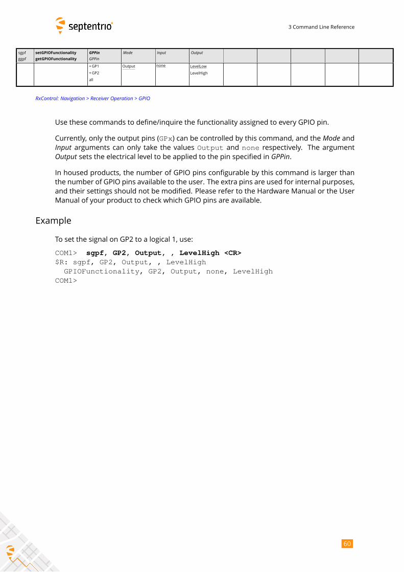
3 Command Line Reference
sgpf
ggpf
setGPIOFunctionality
getGPIOFunctionality
GPPinGPPin
Mode Input Output
+GP1
+GP2
all
Output none LevelLow
LevelHigh
RxControl: Navigation > Receiver Operation > GPIO
Use these commands to define/inquire the functionality assigned to every GPIO pin.
Currently, only the output pins (GPx) can be controlled by this command, and the Mode andInput arguments can only take the values Output and none respectively. The argumentOutput sets the electrical level to be applied to the pin specified in GPPin.In housed products, the number of GPIO pins configurable by this command is larger than
the number of GPIO pins available to the user. The extra pins are used for internal purposes,
and their settings should not be modified. Please refer to the Hardware Manual or the User
Manual of your product to check which GPIO pins are available.
Example
To set the signal on GP2 to a logical 1, use:
COM1> sgpf, GP2, Output, , LevelHigh <CR>$R: sgpf, GP2, Output, , LevelHigh
GPIOFunctionality, GP2, Output, none, LevelHighCOM1>
60
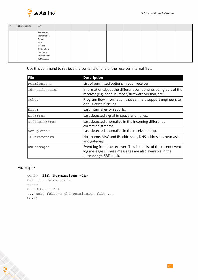
3 Command Line Reference
lif lstInternalFile File
Permissions
Identification
Debug
Error
SisError
DiffCorrError
SetupError
IPParameters
RxMessages
Use this command to retrieve the contents of one of the receiver internal files:
File Description
Permissions List of permitted options in your receiver.
Identification Information about the different components being part of the
receiver (e.g. serial number, firmware version, etc.).
Debug Program flow information that can help support engineers to
debug certain issues.
Error Last internal error reports.
SisError Last detected signal-in-space anomalies.
DiffCorrError Last detected anomalies in the incoming differential
correction streams.
SetupError Last detected anomalies in the receiver setup.
IPParameters Hostname, MAC and IP addresses, DNS addresses, netmask
and gateway.
RxMessages Event log from the receiver. This is the list of the recent event
log messages. These messages are also available in the
RxMessage SBF block.
Example
COM1> lif, Permissions <CR>$R; lif, Permissions---->$-- BLOCK 1 / 1... here follows the permission file ...COM1>
61
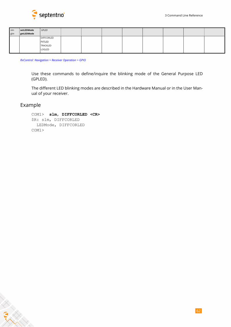
3 Command Line Reference
slm
glm
setLEDMode
getLEDMode
GPLED
DIFFCORLED
PVTLED
TRACKLED
LOGLED
RxControl: Navigation > Receiver Operation > GPIO
Use these commands to define/inquire the blinking mode of the General Purpose LED
(GPLED).
The different LED blinking modes are described in the Hardware Manual or in the User Man-
ual of your receiver.
Example
COM1> slm, DIFFCORLED <CR>$R: slm, DIFFCORLED
LEDMode, DIFFCORLEDCOM1>
62
3 Command Line Reference
lmd lstMIBDescription File (255)
Overview
SBFTable
Use this command to retrieve the ASN.1-compliant syntax of the user command interface.
The name of the command refers to the MIB (Management Information Base), which holds
the whole receiver configuration. There is a one-to-one relationship between the formal MIB
description and the ASCII command-line interface for all exe-, get- and set-commands.
When the value Overview is used, the general syntax of the interface is returned. Withthe value SBFTable, the receiver will output the list of supported SBF blocks and whetherthey can be output at a user-selectable rate or not. The lstMIBDescription commandcan also be called with every supported set-, get- or exe-command (the full name or themnemonic) as argument.
No formal description of the lst-commands can be retrieved with lstMIBDescription.
Examples
COM1> lmd, Overview <CR>$R; lmd, Overview... Here comes the generic command syntax ...COM1>
COM1> lmd, grc <CR>$R; lmd, grc... Here comes the description of getReceiverCapabilities ...COM1>
63
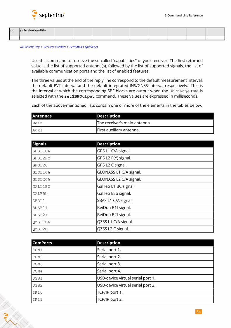
3 Command Line Reference
grc getReceiverCapabilities
RxControl: Help > Receiver Interface > Permitted Capabilities
Use this command to retrieve the so-called "capabilities" of your receiver. The first returned
value is the list of supported antenna(s), followed by the list of supported signals, the list of
available communication ports and the list of enabled features.
The three values at the end of the reply line correspond to the default measurement interval,
the default PVT interval and the default integrated INS/GNSS interval respectively. This is
the interval at which the corresponding SBF blocks are output when the OnChange rate isselected with the setSBFOutput command. These values are expressed in milliseconds.
Each of the above-mentioned lists contain one or more of the elements in the tables below.
Antennas Description
Main The receiver’s main antenna.
Aux1 First auxiliary antenna.
Signals Description
GPSL1CA GPS L1 C/A signal.
GPSL2PY GPS L2 P(Y) signal.
GPSL2C GPS L2 C signal.
GLOL1CA GLONASS L1 C/A signal.
GLOL2CA GLONASS L2 C/A signal.
GALL1BC Galileo L1 BC signal.
GALE5b Galileo E5b signal.
GEOL1 SBAS L1 C/A signal.
BDSB1I BeiDou B1I signal.
BDSB2I BeiDou B2I signal.
QZSL1CA QZSS L1 C/A signal.
QZSL2C QZSS L2 C signal.
ComPorts Description
COM1 Serial port 1.
COM2 Serial port 2.
COM3 Serial port 3.
COM4 Serial port 4.
USB1 USB-device virtual serial port 1.
USB2 USB-device virtual serial port 2.
IP10 TCP/IP port 1.
IP11 TCP/IP port 2.
64
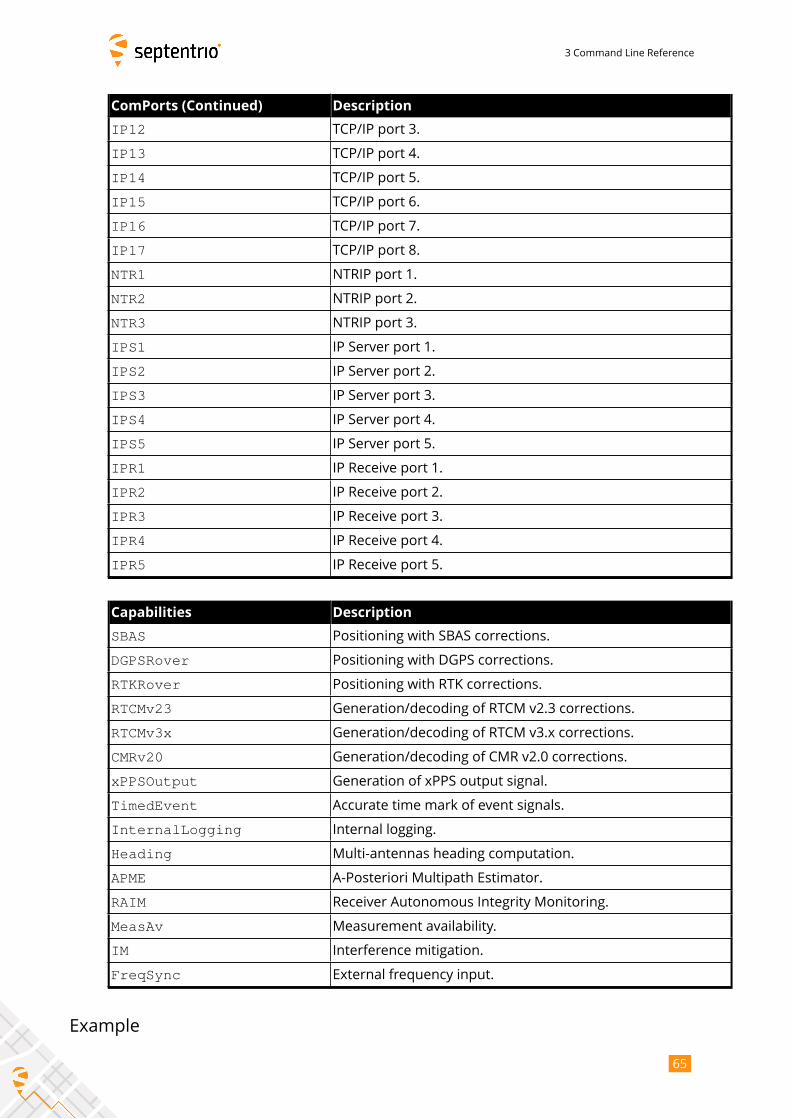
3 Command Line Reference
ComPorts (Continued) Description
IP12 TCP/IP port 3.
IP13 TCP/IP port 4.
IP14 TCP/IP port 5.
IP15 TCP/IP port 6.
IP16 TCP/IP port 7.
IP17 TCP/IP port 8.
NTR1 NTRIP port 1.
NTR2 NTRIP port 2.
NTR3 NTRIP port 3.
IPS1 IP Server port 1.
IPS2 IP Server port 2.
IPS3 IP Server port 3.
IPS4 IP Server port 4.
IPS5 IP Server port 5.
IPR1 IP Receive port 1.
IPR2 IP Receive port 2.
IPR3 IP Receive port 3.
IPR4 IP Receive port 4.
IPR5 IP Receive port 5.
Capabilities Description
SBAS Positioning with SBAS corrections.
DGPSRover Positioning with DGPS corrections.
RTKRover Positioning with RTK corrections.
RTCMv23 Generation/decoding of RTCM v2.3 corrections.
RTCMv3x Generation/decoding of RTCM v3.x corrections.
CMRv20 Generation/decoding of CMR v2.0 corrections.
xPPSOutput Generation of xPPS output signal.
TimedEvent Accurate time mark of event signals.
InternalLogging Internal logging.
Heading Multi-antennas heading computation.
APME A-Posteriori Multipath Estimator.
RAIM Receiver Autonomous Integrity Monitoring.
MeasAv Measurement availability.
IM Interference mitigation.
FreqSync External frequency input.
Example
65
3 Command Line Reference
COM1> grc <CR>$R: grc
ReceiverCapabilities, Main, GPSL1CA+GEOL1, COM1+COM2+COM3+COM4+USB1+USB2,
APME+SBAS, 100, 100, 100COM1>
66
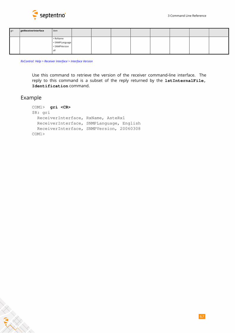
3 Command Line Reference
gri getReceiverInterface Item
+RxName
+ SNMPLanguage
+ SNMPVersion
all
RxControl: Help > Receiver Interface > Interface Version
Use this command to retrieve the version of the receiver command-line interface. The
reply to this command is a subset of the reply returned by the lstInternalFile,Identification command.
Example
COM1> gri <CR>$R: gri
ReceiverInterface, RxName, AsteRx1ReceiverInterface, SNMPLanguage, EnglishReceiverInterface, SNMPVersion, 20060308
COM1>
67
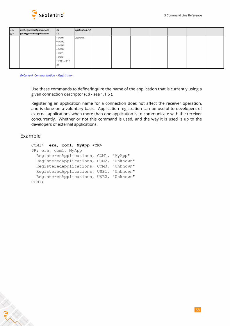
3 Command Line Reference
era
gra
exeRegisteredApplications
getRegisteredApplications
CdCd
Application (12)
+COM1
+COM2
+COM3
+COM4
+USB1
+USB2
+ IP10 ... IP17
all
Unknown
RxControl: Communication > Registration
Use these commands to define/inquire the name of the application that is currently using a
given connection descriptor (Cd - see 1.1.5 ).Registering an application name for a connection does not affect the receiver operation,
and is done on a voluntary basis. Application registration can be useful to developers of
external applications when more than one application is to communicate with the receiver
concurrently. Whether or not this command is used, and the way it is used is up to the
developers of external applications.
Example
COM1> era, com1, MyApp <CR>$R: era, com1, MyApp
RegisteredApplications, COM1, "MyApp"RegisteredApplications, COM2, "Unknown"RegisteredApplications, COM3, "Unknown"RegisteredApplications, USB1, "Unknown"RegisteredApplications, USB2, "Unknown"
COM1>
68
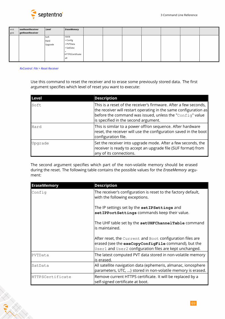
3 Command Line Reference
erst
grst
exeResetReceiver
getResetReceiver
Level EraseMemory
Soft
Hard
Upgrade
none
+Config
+ PVTData
+ SatData
+
HTTPSCertificate
all
RxControl: File > Reset Receiver
Use this command to reset the receiver and to erase some previously stored data. The first
argument specifies which level of reset you want to execute:
Level Description
Soft This is a reset of the receiver’s firmware. After a few seconds,
the receiver will restart operating in the same configuration as
before the command was issued, unless the "Config" valueis specified in the second argument.
Hard This is similar to a power off/on sequence. After hardware
reset, the receiver will use the configuration saved in the boot
configuration file.
Upgrade Set the receiver into upgrade mode. After a few seconds, the
receiver is ready to accept an upgrade file (SUF format) from
any of its connections.
The second argument specifies which part of the non-volatile memory should be erased
during the reset. The following table contains the possible values for the EraseMemory argu-ment:
EraseMemory Description
Config The receiver’s configuration is reset to the factory default,
with the following exceptions.
The IP settings set by the setIPSettings andsetIPPortSettings commands keep their value.
The UHF table set by the setUHFChannelTable commandis maintained.
After reset, the Current and Boot configuration files areerased (see the exeCopyConfigFile command), but theUser1 and User2 configuration files are kept unchanged.
PVTData The latest computed PVT data stored in non-volatile memory
is erased.
SatData All satellite navigation data (ephemeris, almanac, ionosphere
parameters, UTC, ...) stored in non-volatile memory is erased.
HTTPSCertificate Remove current HTTPS certificate. It will be replaced by a
self-signed certificate at boot.
69
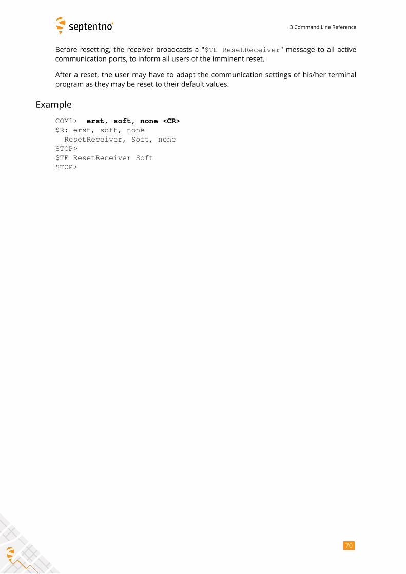
3 Command Line Reference
Before resetting, the receiver broadcasts a "$TE ResetReceiver" message to all activecommunication ports, to inform all users of the imminent reset.
After a reset, the user may have to adapt the communication settings of his/her terminal
program as they may be reset to their default values.
Example
COM1> erst, soft, none <CR>$R: erst, soft, none
ResetReceiver, Soft, noneSTOP>$TE ResetReceiver SoftSTOP>
70
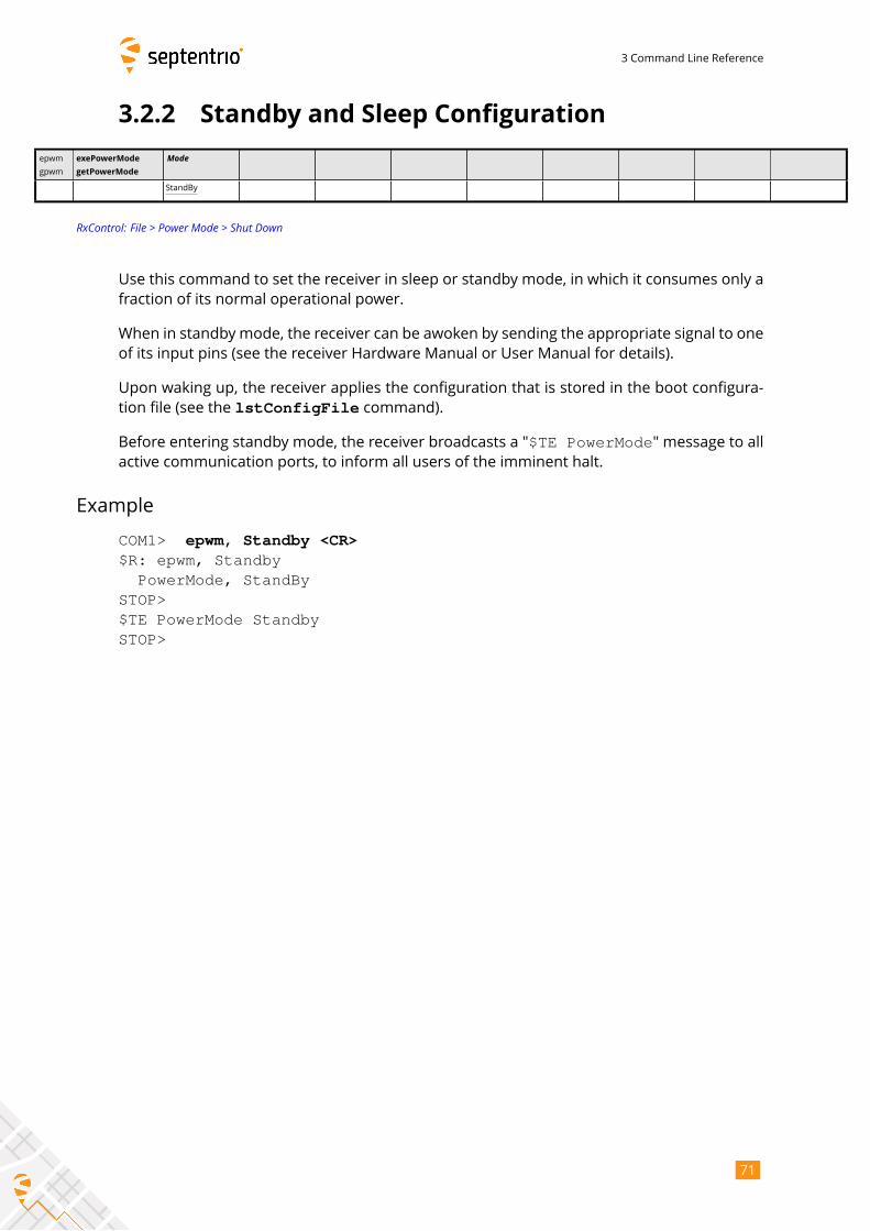
3 Command Line Reference
3.2.2 Standby and Sleep Configuration
epwm
gpwm
exePowerMode
getPowerMode
Mode
StandBy
RxControl: File > Power Mode > Shut Down
Use this command to set the receiver in sleep or standby mode, in which it consumes only a
fraction of its normal operational power.
When in standby mode, the receiver can be awoken by sending the appropriate signal to one
of its input pins (see the receiver Hardware Manual or User Manual for details).
Upon waking up, the receiver applies the configuration that is stored in the boot configura-
tion file (see the lstConfigFile command).
Before entering standby mode, the receiver broadcasts a "$TE PowerMode" message to allactive communication ports, to inform all users of the imminent halt.
Example
COM1> epwm, Standby <CR>$R: epwm, Standby
PowerMode, StandBySTOP>$TE PowerMode StandbySTOP>
71
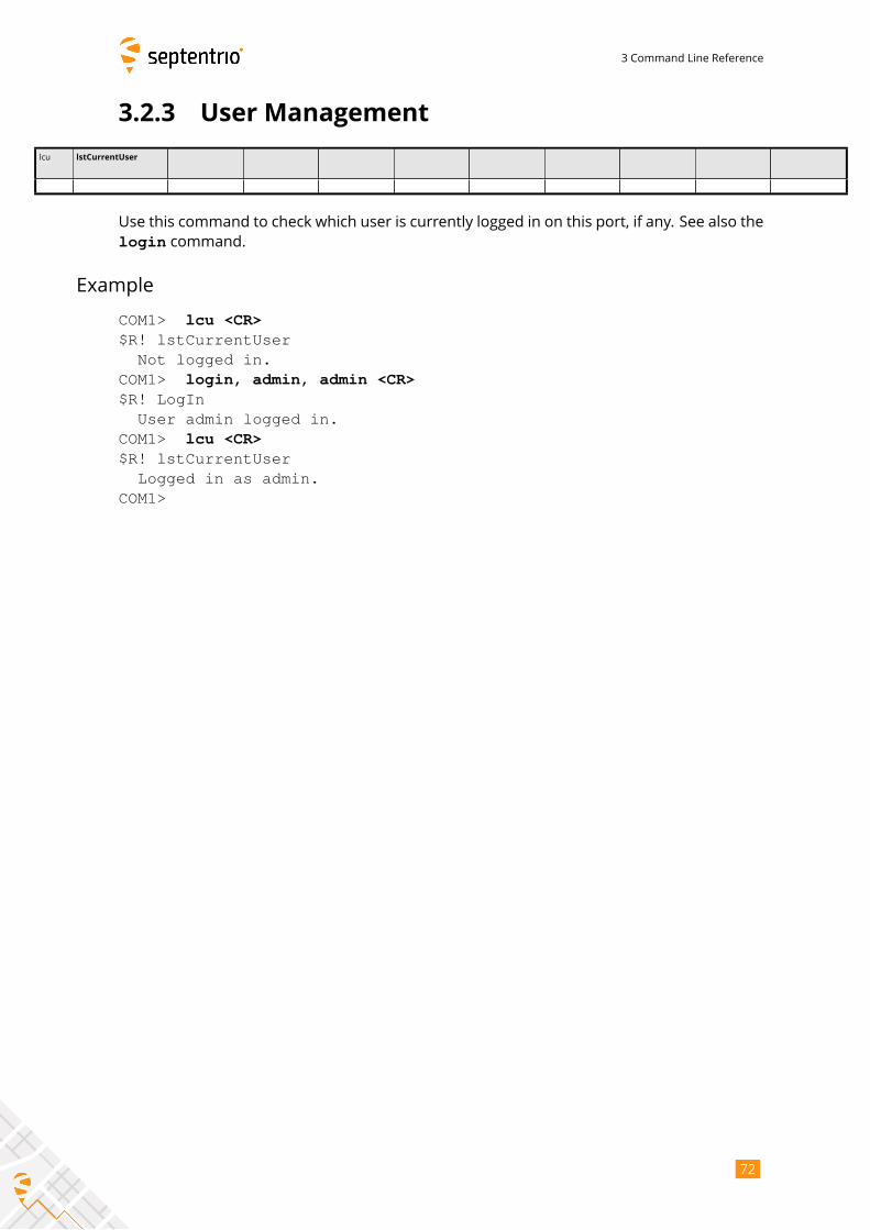
3 Command Line Reference
3.2.3 User Management
lcu lstCurrentUser
Use this command to check which user is currently logged in on this port, if any. See also the
login command.
Example
COM1> lcu <CR>$R! lstCurrentUser
Not logged in.COM1> login, admin, admin <CR>$R! LogIn
User admin logged in.COM1> lcu <CR>$R! lstCurrentUser
Logged in as admin.COM1>
72
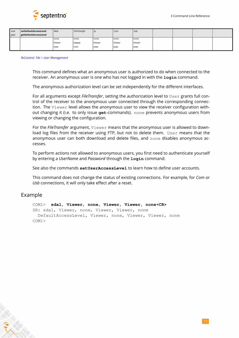
3 Command Line Reference
sdal
gdal
setDefaultAccessLevel
getDefaultAccessLevel
Web FileTransfer Ip Com Usbnone
Viewer
User
none
Viewer
User
none
Viewer
User
none
Viewer
User
none
Viewer
User
RxControl: File > User Management
This command defines what an anonymous user is authorized to do when connected to the
receiver. An anonymous user is one who has not logged in with the login command.
The anonymous authorization level can be set independently for the different interfaces.
For all arguments except FileTransfer, setting the authorization level to User grants full con-trol of the receiver to the anonymous user connected through the corresponding connec-
tion. The Viewer level allows the anonymous user to view the receiver configuration with-out changing it (i.e. to only issue get-commands). none prevents anonymous users fromviewing or changing the configuration.
For the FileTransfer argument, Viewermeans that the anonymous user is allowed to down-load log files from the receiver using FTP, but not to delete them. User means that theanonymous user can both download and delete files, and none disables anonymous ac-cesses.
To perform actions not allowed to anonymous users, you first need to authenticate yourself
by entering a UserName and Password through the login command.See also the commands setUserAccessLevel to learn how to define user accounts.
This command does not change the status of existing connections. For example, for Com orUsb connections, it will only take effect after a reset.Example
COM1> sdal, Viewer, none, Viewer, Viewer, none<CR>$R: sdal, Viewer, none, Viewer, Viewer, none
DefaultAccessLevel, Viewer, none, Viewer, Viewer, noneCOM1>
73
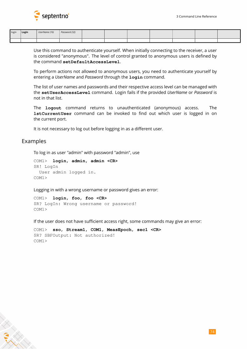
3 Command Line Reference
login LogIn UserName (16) Password (32)
Use this command to authenticate yourself. When initially connecting to the receiver, a user
is considered "anonymous". The level of control granted to anonymous users is defined by
the command setDefaultAccessLevel.
To perform actions not allowed to anonymous users, you need to authenticate yourself by
entering a UserName and Password through the login command.The list of user names and passwords and their respective access level can be managed with
the setUserAccessLevel command. Login fails if the provided UserName or Password isnot in that list.
The logout command returns to unauthenticated (anonymous) access. The
lstCurrentUser command can be invoked to find out which user is logged in on
the current port.
It is not necessary to log out before logging in as a different user.
Examples
To log in as user "admin" with password "admin", use
COM1> login, admin, admin <CR>$R! LogIn
User admin logged in.COM1>
Logging in with a wrong username or password gives an error:
COM1> login, foo, foo <CR>$R? LogIn: Wrong username or password!COM1>
If the user does not have sufficient access right, some commands may give an error:
COM1> sso, Stream1, COM1, MeasEpoch, sec1 <CR>$R? SBFOutput: Not authorized!COM1>
74
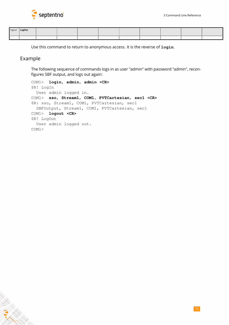
3 Command Line Reference
logout LogOut
Use this command to return to anonymous access. It is the reverse of login.
Example
The following sequence of commands logs in as user "admin" with password "admin", recon-
figures SBF output, and logs out again:
COM1> login, admin, admin <CR>$R! LogIn
User admin logged in.COM1> sso, Stream1, COM1, PVTCartesian, sec1 <CR>$R: sso, Stream1, COM1, PVTCartesian, sec1
SBFOutput, Stream1, COM1, PVTCartesian, sec1COM1> logout <CR>$R! LogOut
User admin logged out.COM1>
75
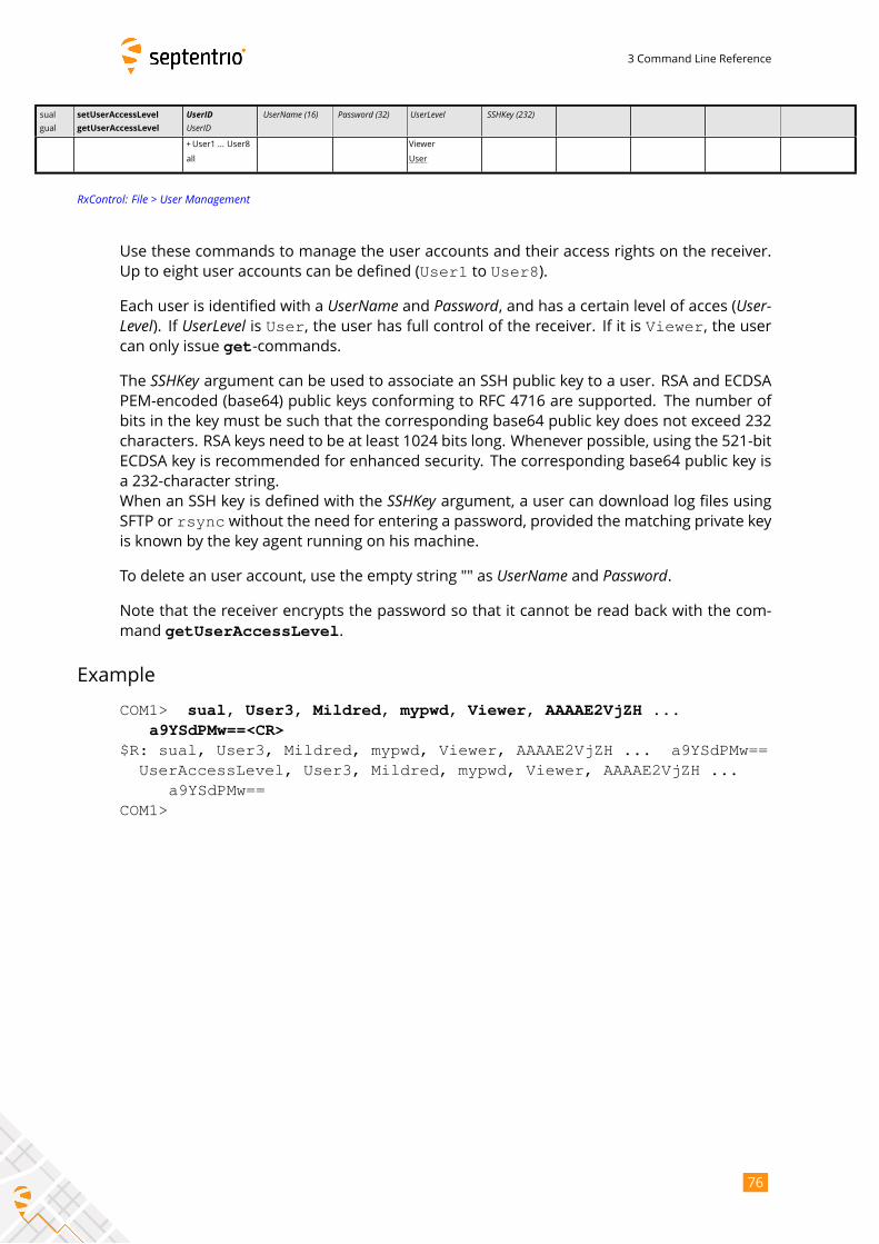
3 Command Line Reference
sual
gual
setUserAccessLevel
getUserAccessLevel
UserIDUserID
UserName (16) Password (32) UserLevel SSHKey (232)
+User1 ... User8
all
Viewer
User
RxControl: File > User Management
Use these commands to manage the user accounts and their access rights on the receiver.
Up to eight user accounts can be defined (User1 to User8).
Each user is identified with a UserName and Password, and has a certain level of acces (User-Level). If UserLevel is User, the user has full control of the receiver. If it is Viewer, the usercan only issue get-commands.
The SSHKey argument can be used to associate an SSH public key to a user. RSA and ECDSAPEM-encoded (base64) public keys conforming to RFC 4716 are supported. The number of
bits in the key must be such that the corresponding base64 public key does not exceed 232
characters. RSA keys need to be at least 1024 bits long. Whenever possible, using the 521-bit
ECDSA key is recommended for enhanced security. The corresponding base64 public key is
a 232-character string.
When an SSH key is defined with the SSHKey argument, a user can download log files usingSFTP or rsync without the need for entering a password, provided the matching private keyis known by the key agent running on his machine.
To delete an user account, use the empty string "" as UserName and Password.Note that the receiver encrypts the password so that it cannot be read back with the com-
mand getUserAccessLevel.
Example
COM1> sual, User3, Mildred, mypwd, Viewer, AAAAE2VjZH ...a9YSdPMw==<CR>
$R: sual, User3, Mildred, mypwd, Viewer, AAAAE2VjZH ... a9YSdPMw==UserAccessLevel, User3, Mildred, mypwd, Viewer, AAAAE2VjZH ...
a9YSdPMw==COM1>
76
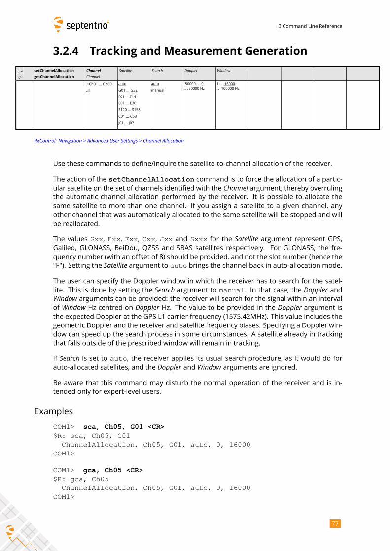
3 Command Line Reference
3.2.4 Tracking and Measurement Generation
sca
gca
setChannelAllocation
getChannelAllocation
ChannelChannel
Satellite Search Doppler Window
+Ch01 ... Ch60
all
auto
G01 ... G32
F01 ... F14
E01 ... E36
S120 ... S158
C01 ... C63
J01 ... J07
auto
manual
-50000 . . . 0
. . . 50000 Hz
1 . . . 16000
. . . 100000 Hz
RxControl: Navigation > Advanced User Settings > Channel Allocation
Use these commands to define/inquire the satellite-to-channel allocation of the receiver.
The action of the setChannelAllocation command is to force the allocation of a partic-ular satellite on the set of channels identified with the Channel argument, thereby overrulingthe automatic channel allocation performed by the receiver. It is possible to allocate the
same satellite to more than one channel. If you assign a satellite to a given channel, any
other channel that was automatically allocated to the same satellite will be stopped and will
be reallocated.
The values Gxx, Exx, Fxx, Cxx, Jxx and Sxxx for the Satellite argument represent GPS,Galileo, GLONASS, BeiDou, QZSS and SBAS satellites respectively. For GLONASS, the fre-
quency number (with an offset of 8) should be provided, and not the slot number (hence the
"F"). Setting the Satellite argument to auto brings the channel back in auto-allocation mode.The user can specify the Doppler window in which the receiver has to search for the satel-
lite. This is done by setting the Search argument to manual. In that case, the Doppler andWindow arguments can be provided: the receiver will search for the signal within an intervalof Window Hz centred on Doppler Hz. The value to be provided in the Doppler argument isthe expected Doppler at the GPS L1 carrier frequency (1575.42MHz). This value includes the
geometric Doppler and the receiver and satellite frequency biases. Specifying a Doppler win-
dow can speed up the search process in some circumstances. A satellite already in tracking
that falls outside of the prescribed window will remain in tracking.
If Search is set to auto, the receiver applies its usual search procedure, as it would do forauto-allocated satellites, and the Doppler and Window arguments are ignored.Be aware that this command may disturb the normal operation of the receiver and is in-
tended only for expert-level users.
Examples
COM1> sca, Ch05, G01 <CR>$R: sca, Ch05, G01
ChannelAllocation, Ch05, G01, auto, 0, 16000COM1>
COM1> gca, Ch05 <CR>$R: gca, Ch05
ChannelAllocation, Ch05, G01, auto, 0, 16000COM1>
77
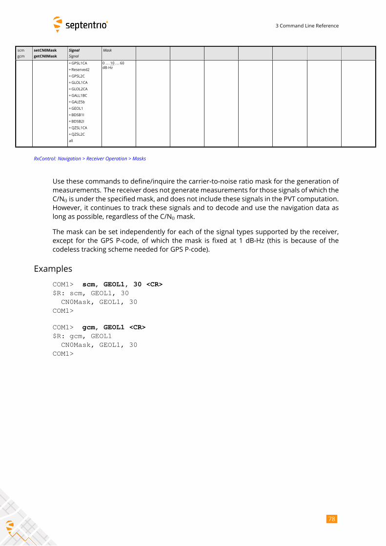
3 Command Line Reference
scm
gcm
setCN0Mask
getCN0Mask
SignalSignal
Mask
+GPSL1CA
+Reserved2
+GPSL2C
+GLOL1CA
+GLOL2CA
+GALL1BC
+GALE5b
+GEOL1
+BDSB1I
+BDSB2I
+QZSL1CA
+QZSL2C
all
0 . . . 10 . . . 60
dB-Hz
RxControl: Navigation > Receiver Operation > Masks
Use these commands to define/inquire the carrier-to-noise ratio mask for the generation of
measurements. The receiver does not generatemeasurements for those signals of which the
C/N0 is under the specifiedmask, and does not include these signals in the PVT computation.
However, it continues to track these signals and to decode and use the navigation data as
long as possible, regardless of the C/N0 mask.
The mask can be set independently for each of the signal types supported by the receiver,
except for the GPS P-code, of which the mask is fixed at 1 dB-Hz (this is because of the
codeless tracking scheme needed for GPS P-code).
Examples
COM1> scm, GEOL1, 30 <CR>$R: scm, GEOL1, 30
CN0Mask, GEOL1, 30COM1>
COM1> gcm, GEOL1 <CR>$R: gcm, GEOL1
CN0Mask, GEOL1, 30COM1>
78
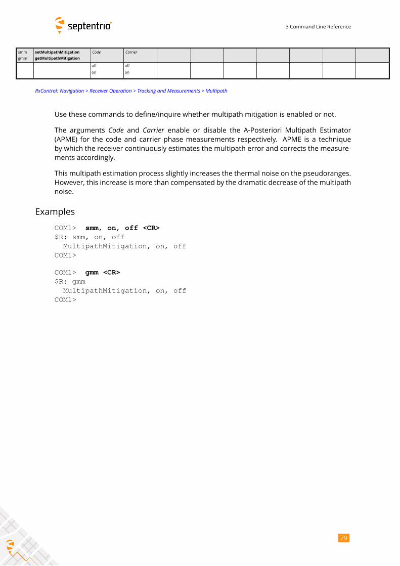
3 Command Line Reference
smm
gmm
setMultipathMitigation
getMultipathMitigation
Code Carrier
off
on
off
on
RxControl: Navigation > Receiver Operation > Tracking and Measurements > Multipath
Use these commands to define/inquire whether multipath mitigation is enabled or not.
The arguments Code and Carrier enable or disable the A-Posteriori Multipath Estimator(APME) for the code and carrier phase measurements respectively. APME is a technique
by which the receiver continuously estimates the multipath error and corrects the measure-
ments accordingly.
This multipath estimation process slightly increases the thermal noise on the pseudoranges.
However, this increase is more than compensated by the dramatic decrease of the multipath
noise.
Examples
COM1> smm, on, off <CR>$R: smm, on, off
MultipathMitigation, on, offCOM1>
COM1> gmm <CR>$R: gmm
MultipathMitigation, on, offCOM1>
79
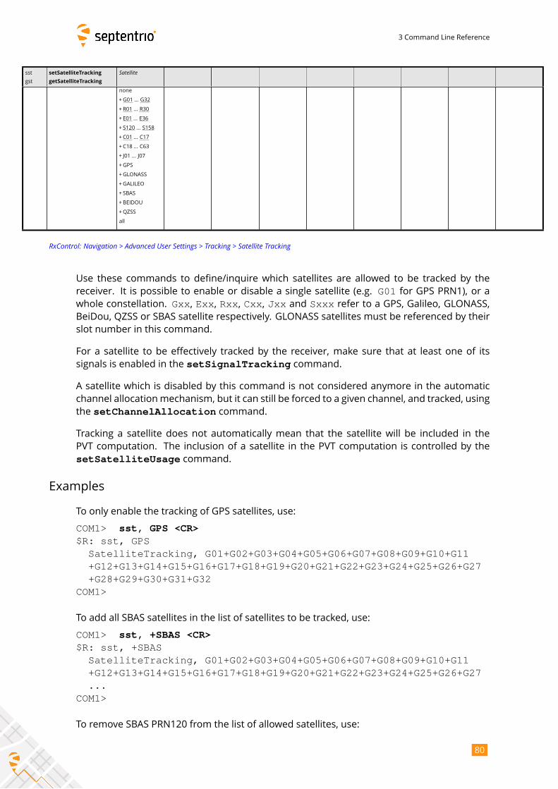
3 Command Line Reference
sst
gst
setSatelliteTracking
getSatelliteTracking
Satellitenone
+G01 ... G32
+R01 ... R30
+ E01 ... E36
+ S120 ... S158
+C01 ... C17
+C18 ... C63
+ J01 ... J07
+GPS
+GLONASS
+GALILEO
+ SBAS
+BEIDOU
+QZSS
all
RxControl: Navigation > Advanced User Settings > Tracking > Satellite Tracking
Use these commands to define/inquire which satellites are allowed to be tracked by the
receiver. It is possible to enable or disable a single satellite (e.g. G01 for GPS PRN1), or awhole constellation. Gxx, Exx, Rxx, Cxx, Jxx and Sxxx refer to a GPS, Galileo, GLONASS,BeiDou, QZSS or SBAS satellite respectively. GLONASS satellites must be referenced by their
slot number in this command.
For a satellite to be effectively tracked by the receiver, make sure that at least one of its
signals is enabled in the setSignalTracking command.
A satellite which is disabled by this command is not considered anymore in the automatic
channel allocationmechanism, but it can still be forced to a given channel, and tracked, using
the setChannelAllocation command.
Tracking a satellite does not automatically mean that the satellite will be included in the
PVT computation. The inclusion of a satellite in the PVT computation is controlled by the
setSatelliteUsage command.
Examples
To only enable the tracking of GPS satellites, use:
COM1> sst, GPS <CR>$R: sst, GPS
SatelliteTracking, G01+G02+G03+G04+G05+G06+G07+G08+G09+G10+G11+G12+G13+G14+G15+G16+G17+G18+G19+G20+G21+G22+G23+G24+G25+G26+G27+G28+G29+G30+G31+G32
COM1>
To add all SBAS satellites in the list of satellites to be tracked, use:
COM1> sst, +SBAS <CR>$R: sst, +SBAS
SatelliteTracking, G01+G02+G03+G04+G05+G06+G07+G08+G09+G10+G11+G12+G13+G14+G15+G16+G17+G18+G19+G20+G21+G22+G23+G24+G25+G26+G27...
COM1>
To remove SBAS PRN120 from the list of allowed satellites, use:
80
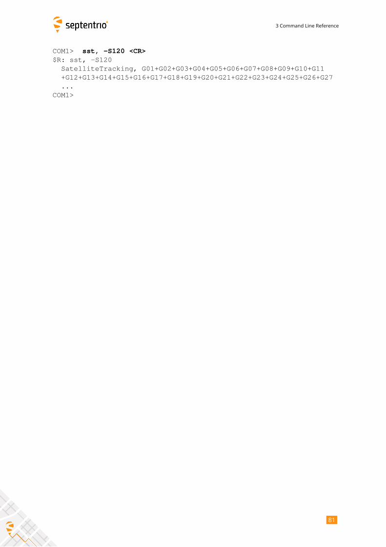
3 Command Line Reference
COM1> sst, -S120 <CR>$R: sst, -S120
SatelliteTracking, G01+G02+G03+G04+G05+G06+G07+G08+G09+G10+G11+G12+G13+G14+G15+G16+G17+G18+G19+G20+G21+G22+G23+G24+G25+G26+G27...
COM1>
81
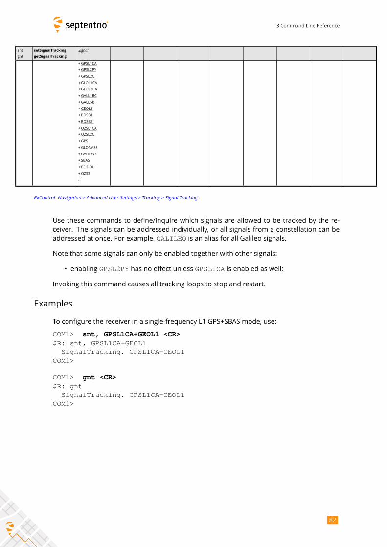
3 Command Line Reference
snt
gnt
setSignalTracking
getSignalTracking
Signal
+GPSL1CA
+GPSL2PY
+GPSL2C
+GLOL1CA
+GLOL2CA
+GALL1BC
+GALE5b
+GEOL1
+BDSB1I
+BDSB2I
+QZSL1CA
+QZSL2C
+GPS
+GLONASS
+GALILEO
+ SBAS
+BEIDOU
+QZSS
all
RxControl: Navigation > Advanced User Settings > Tracking > Signal Tracking
Use these commands to define/inquire which signals are allowed to be tracked by the re-
ceiver. The signals can be addressed individually, or all signals from a constellation can be
addressed at once. For example, GALILEO is an alias for all Galileo signals.
Note that some signals can only be enabled together with other signals:
• enabling GPSL2PY has no effect unless GPSL1CA is enabled as well;
Invoking this command causes all tracking loops to stop and restart.
Examples
To configure the receiver in a single-frequency L1 GPS+SBAS mode, use:
COM1> snt, GPSL1CA+GEOL1 <CR>$R: snt, GPSL1CA+GEOL1
SignalTracking, GPSL1CA+GEOL1COM1>
COM1> gnt <CR>$R: gnt
SignalTracking, GPSL1CA+GEOL1COM1>
82
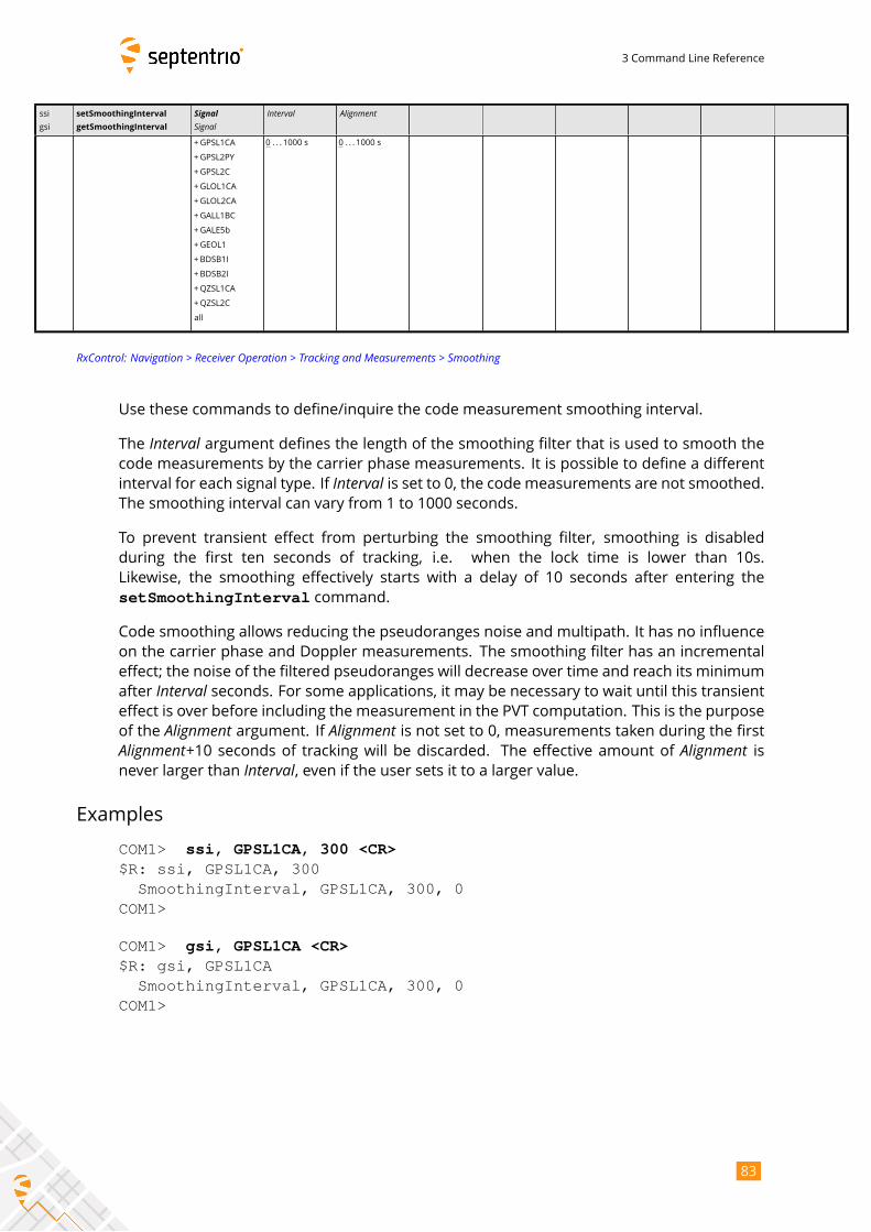
3 Command Line Reference
ssi
gsi
setSmoothingInterval
getSmoothingInterval
SignalSignal
Interval Alignment
+GPSL1CA
+GPSL2PY
+GPSL2C
+GLOL1CA
+GLOL2CA
+GALL1BC
+GALE5b
+GEOL1
+BDSB1I
+BDSB2I
+QZSL1CA
+QZSL2C
all
0 . . . 1000 s 0 . . . 1000 s
RxControl: Navigation > Receiver Operation > Tracking and Measurements > Smoothing
Use these commands to define/inquire the code measurement smoothing interval.
The Interval argument defines the length of the smoothing filter that is used to smooth thecode measurements by the carrier phase measurements. It is possible to define a different
interval for each signal type. If Interval is set to 0, the code measurements are not smoothed.The smoothing interval can vary from 1 to 1000 seconds.
To prevent transient effect from perturbing the smoothing filter, smoothing is disabled
during the first ten seconds of tracking, i.e. when the lock time is lower than 10s.
Likewise, the smoothing effectively starts with a delay of 10 seconds after entering the
setSmoothingInterval command.
Code smoothing allows reducing the pseudoranges noise and multipath. It has no influence
on the carrier phase and Doppler measurements. The smoothing filter has an incremental
effect; the noise of the filtered pseudoranges will decrease over time and reach its minimum
after Interval seconds. For some applications, it may be necessary to wait until this transienteffect is over before including the measurement in the PVT computation. This is the purpose
of the Alignment argument. If Alignment is not set to 0, measurements taken during the firstAlignment+10 seconds of tracking will be discarded. The effective amount of Alignment isnever larger than Interval, even if the user sets it to a larger value.
Examples
COM1> ssi, GPSL1CA, 300 <CR>$R: ssi, GPSL1CA, 300
SmoothingInterval, GPSL1CA, 300, 0COM1>
COM1> gsi, GPSL1CA <CR>$R: gsi, GPSL1CA
SmoothingInterval, GPSL1CA, 300, 0COM1>
83
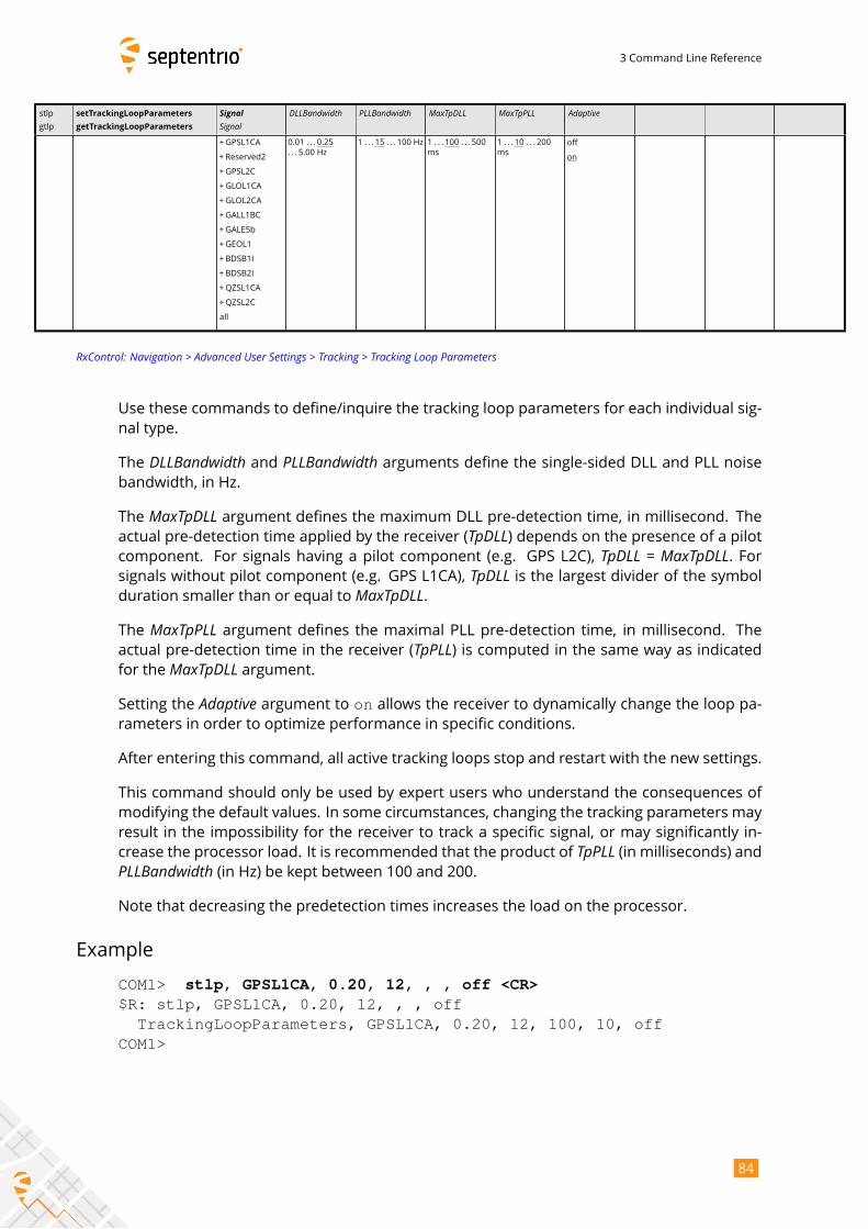
3 Command Line Reference
stlp
gtlp
setTrackingLoopParameters
getTrackingLoopParameters
SignalSignal
DLLBandwidth PLLBandwidth MaxTpDLL MaxTpPLL Adaptive
+GPSL1CA
+Reserved2
+GPSL2C
+GLOL1CA
+GLOL2CA
+GALL1BC
+GALE5b
+GEOL1
+BDSB1I
+BDSB2I
+QZSL1CA
+QZSL2C
all
0.01 . . . 0.25
. . . 5.00 Hz
1 . . . 15 . . . 100 Hz 1 . . . 100 . . . 500
ms
1 . . . 10 . . . 200
ms
off
on
RxControl: Navigation > Advanced User Settings > Tracking > Tracking Loop Parameters
Use these commands to define/inquire the tracking loop parameters for each individual sig-
nal type.
The DLLBandwidth and PLLBandwidth arguments define the single-sided DLL and PLL noisebandwidth, in Hz.
The MaxTpDLL argument defines the maximum DLL pre-detection time, in millisecond. Theactual pre-detection time applied by the receiver (TpDLL) depends on the presence of a pilotcomponent. For signals having a pilot component (e.g. GPS L2C), TpDLL = MaxTpDLL. Forsignals without pilot component (e.g. GPS L1CA), TpDLL is the largest divider of the symbolduration smaller than or equal to MaxTpDLL.The MaxTpPLL argument defines the maximal PLL pre-detection time, in millisecond. Theactual pre-detection time in the receiver (TpPLL) is computed in the same way as indicatedfor the MaxTpDLL argument.Setting the Adaptive argument to on allows the receiver to dynamically change the loop pa-rameters in order to optimize performance in specific conditions.
After entering this command, all active tracking loops stop and restart with the new settings.
This command should only be used by expert users who understand the consequences of
modifying the default values. In some circumstances, changing the tracking parameters may
result in the impossibility for the receiver to track a specific signal, or may significantly in-
crease the processor load. It is recommended that the product of TpPLL (in milliseconds) andPLLBandwidth (in Hz) be kept between 100 and 200.Note that decreasing the predetection times increases the load on the processor.
Example
COM1> stlp, GPSL1CA, 0.20, 12, , , off <CR>$R: stlp, GPSL1CA, 0.20, 12, , , off
TrackingLoopParameters, GPSL1CA, 0.20, 12, 100, 10, offCOM1>
84
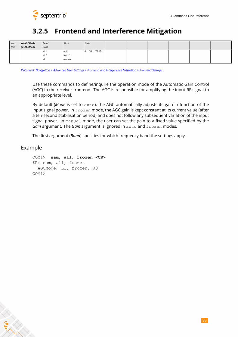
3 Command Line Reference
3.2.5 Frontend and Interference Mitigation
sam
gam
setAGCMode
getAGCMode
BandBand
Mode Gain
+ L1
+ L2
all
auto
frozen
manual
0 . . . 35 . . . 70 dB
RxControl: Navigation > Advanced User Settings > Frontend and Interference Mitigation > Frontend Settings
Use these commands to define/inquire the operation mode of the Automatic Gain Control
(AGC) in the receiver frontend. The AGC is responsible for amplifying the input RF signal to
an appropriate level.
By default (Mode is set to auto), the AGC automatically adjusts its gain in function of theinput signal power. In frozenmode, the AGC gain is kept constant at its current value (aftera ten-second stabilisation period) and does not follow any subsequent variation of the input
signal power. In manual mode, the user can set the gain to a fixed value specified by theGain argument. The Gain argument is ignored in auto and frozenmodes.The first argument (Band) specifies for which frequency band the settings apply.
Example
COM1> sam, all, frozen <CR>$R: sam, all, frozen
AGCMode, L1, frozen, 30COM1>
85
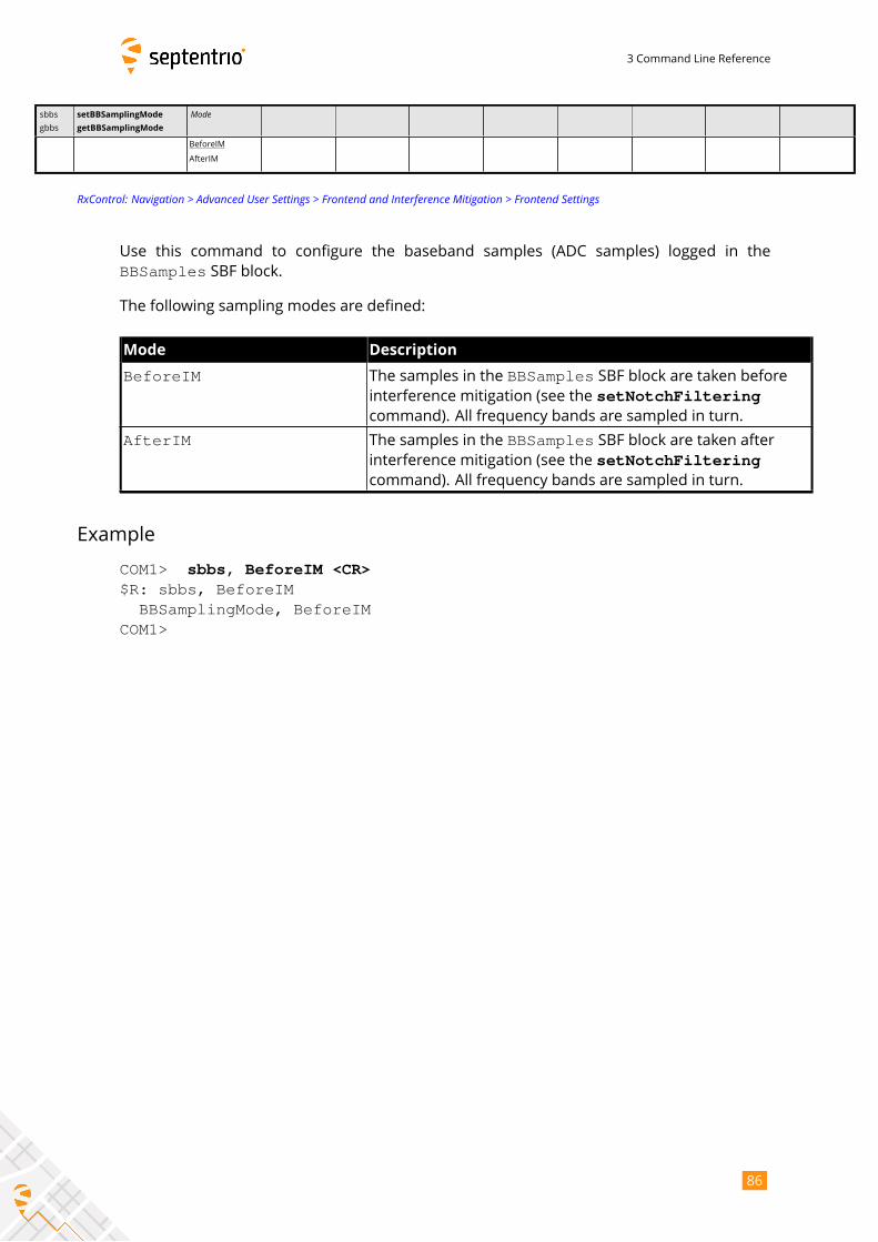
3 Command Line Reference
sbbs
gbbs
setBBSamplingMode
getBBSamplingMode
Mode
BeforeIM
AfterIM
RxControl: Navigation > Advanced User Settings > Frontend and Interference Mitigation > Frontend Settings
Use this command to configure the baseband samples (ADC samples) logged in the
BBSamples SBF block.
The following sampling modes are defined:
Mode Description
BeforeIM The samples in the BBSamples SBF block are taken beforeinterference mitigation (see the setNotchFilteringcommand). All frequency bands are sampled in turn.
AfterIM The samples in the BBSamples SBF block are taken afterinterference mitigation (see the setNotchFilteringcommand). All frequency bands are sampled in turn.
Example
COM1> sbbs, BeforeIM <CR>$R: sbbs, BeforeIM
BBSamplingMode, BeforeIMCOM1>
86
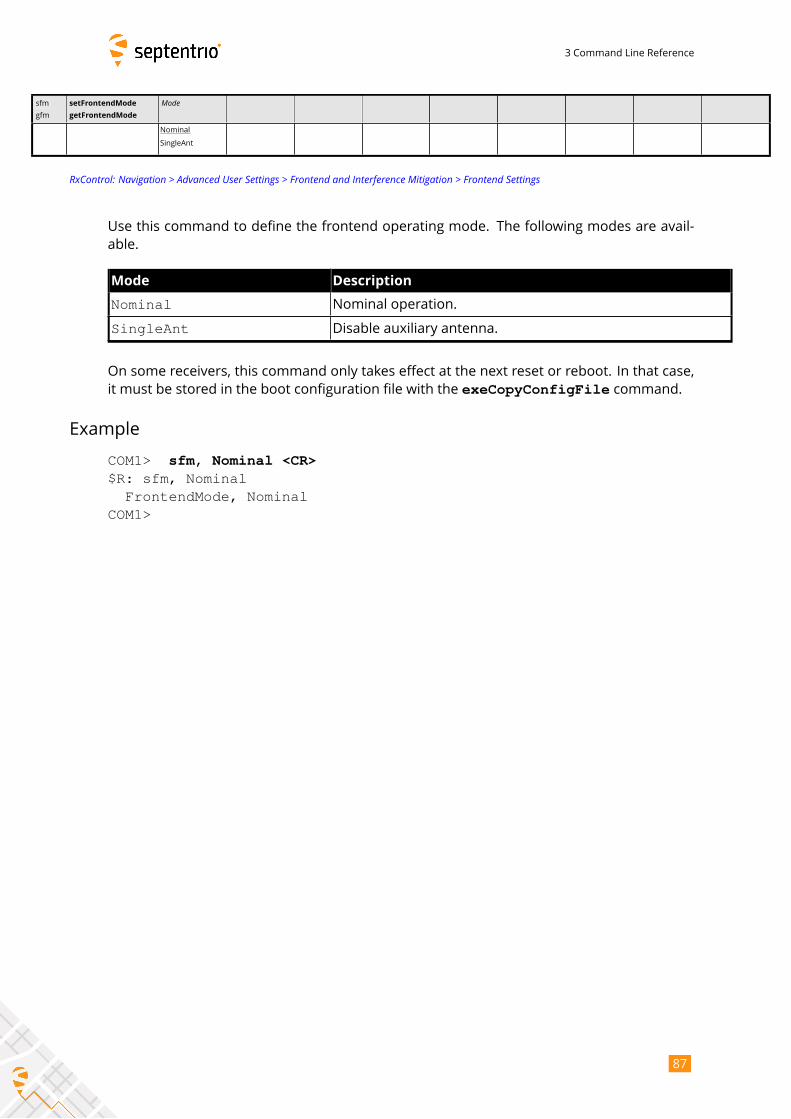
3 Command Line Reference
sfm
gfm
setFrontendMode
getFrontendMode
Mode
Nominal
SingleAnt
RxControl: Navigation > Advanced User Settings > Frontend and Interference Mitigation > Frontend Settings
Use this command to define the frontend operating mode. The following modes are avail-
able.
Mode Description
Nominal Nominal operation.
SingleAnt Disable auxiliary antenna.
On some receivers, this command only takes effect at the next reset or reboot. In that case,
it must be stored in the boot configuration file with the exeCopyConfigFile command.
Example
COM1> sfm, Nominal <CR>$R: sfm, Nominal
FrontendMode, NominalCOM1>
87
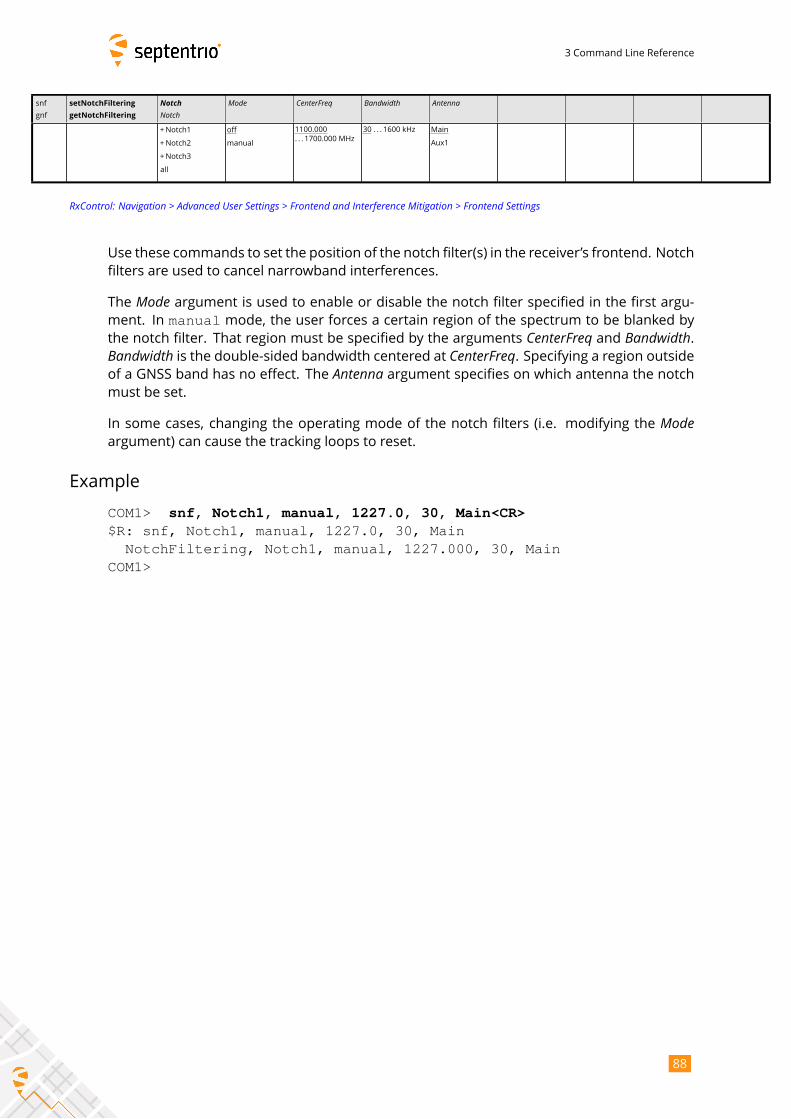
3 Command Line Reference
snf
gnf
setNotchFiltering
getNotchFiltering
NotchNotch
Mode CenterFreq Bandwidth Antenna
+Notch1
+Notch2
+Notch3
all
off
manual
1100.000
. . . 1700.000 MHz
30 . . . 1600 kHz Main
Aux1
RxControl: Navigation > Advanced User Settings > Frontend and Interference Mitigation > Frontend Settings
Use these commands to set the position of the notch filter(s) in the receiver’s frontend. Notch
filters are used to cancel narrowband interferences.
The Mode argument is used to enable or disable the notch filter specified in the first argu-ment. In manual mode, the user forces a certain region of the spectrum to be blanked bythe notch filter. That region must be specified by the arguments CenterFreq and Bandwidth.Bandwidth is the double-sided bandwidth centered at CenterFreq. Specifying a region outsideof a GNSS band has no effect. The Antenna argument specifies on which antenna the notchmust be set.
In some cases, changing the operating mode of the notch filters (i.e. modifying the Modeargument) can cause the tracking loops to reset.
Example
COM1> snf, Notch1, manual, 1227.0, 30, Main<CR>$R: snf, Notch1, manual, 1227.0, 30, Main
NotchFiltering, Notch1, manual, 1227.000, 30, MainCOM1>
88
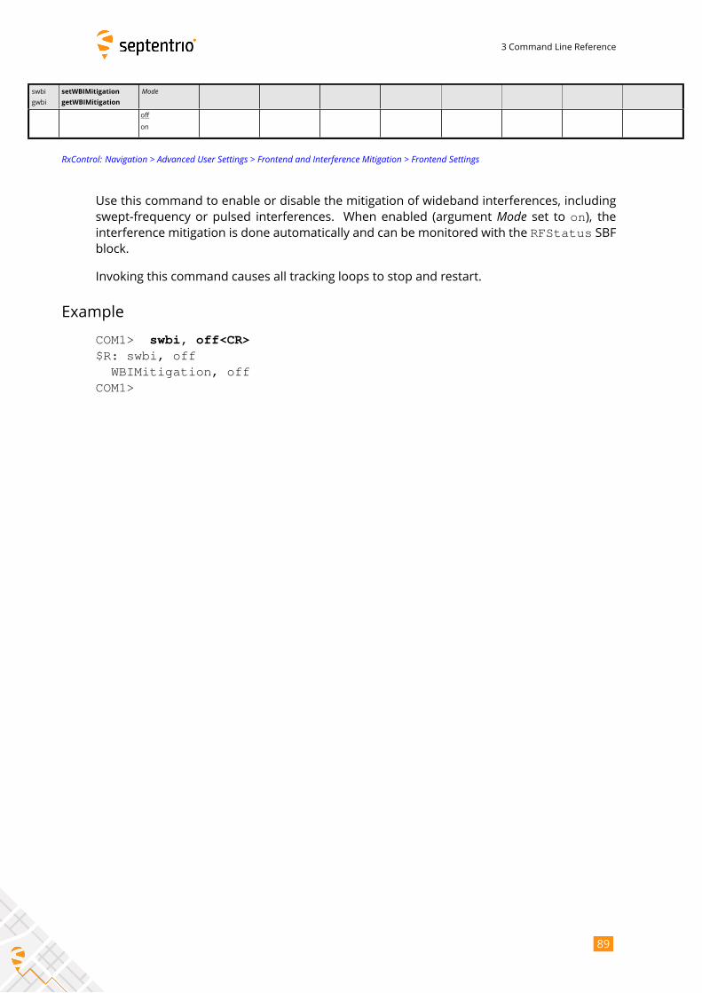
3 Command Line Reference
swbi
gwbi
setWBIMitigation
getWBIMitigation
Mode
off
on
RxControl: Navigation > Advanced User Settings > Frontend and Interference Mitigation > Frontend Settings
Use this command to enable or disable the mitigation of wideband interferences, including
swept-frequency or pulsed interferences. When enabled (argument Mode set to on), theinterference mitigation is done automatically and can be monitored with the RFStatus SBFblock.
Invoking this command causes all tracking loops to stop and restart.
Example
COM1> swbi, off<CR>$R: swbi, off
WBIMitigation, offCOM1>
89
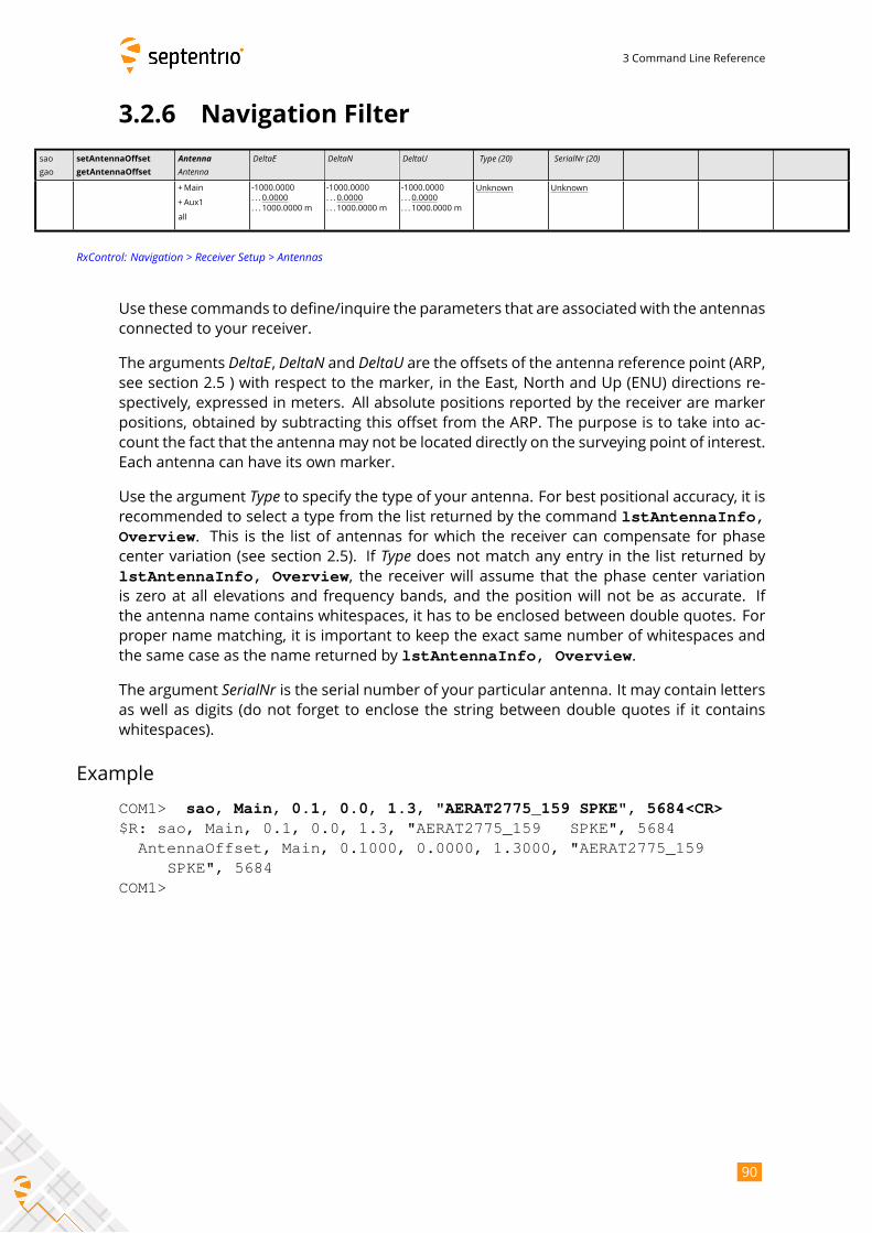
3 Command Line Reference
3.2.6 Navigation Filter
sao
gao
setAntennaOffset
getAntennaOffset
AntennaAntenna
DeltaE DeltaN DeltaU Type (20) SerialNr (20)
+Main
+Aux1
all
-1000.0000
. . . 0.0000
. . . 1000.0000 m
-1000.0000
. . . 0.0000
. . . 1000.0000 m
-1000.0000
. . . 0.0000
. . . 1000.0000 m
Unknown Unknown
RxControl: Navigation > Receiver Setup > Antennas
Use these commands to define/inquire the parameters that are associatedwith the antennas
connected to your receiver.
The arguments DeltaE, DeltaN and DeltaU are the offsets of the antenna reference point (ARP,see section 2.5 ) with respect to the marker, in the East, North and Up (ENU) directions re-
spectively, expressed in meters. All absolute positions reported by the receiver are marker
positions, obtained by subtracting this offset from the ARP. The purpose is to take into ac-
count the fact that the antennamay not be located directly on the surveying point of interest.
Each antenna can have its own marker.
Use the argument Type to specify the type of your antenna. For best positional accuracy, it isrecommended to select a type from the list returned by the command lstAntennaInfo,Overview. This is the list of antennas for which the receiver can compensate for phasecenter variation (see section 2.5). If Type does not match any entry in the list returned bylstAntennaInfo, Overview, the receiver will assume that the phase center variationis zero at all elevations and frequency bands, and the position will not be as accurate. If
the antenna name contains whitespaces, it has to be enclosed between double quotes. For
proper name matching, it is important to keep the exact same number of whitespaces and
the same case as the name returned by lstAntennaInfo, Overview.
The argument SerialNr is the serial number of your particular antenna. It may contain lettersas well as digits (do not forget to enclose the string between double quotes if it contains
whitespaces).
Example
COM1> sao, Main, 0.1, 0.0, 1.3, "AERAT2775_159 SPKE", 5684<CR>$R: sao, Main, 0.1, 0.0, 1.3, "AERAT2775_159 SPKE", 5684
AntennaOffset, Main, 0.1000, 0.0000, 1.3000, "AERAT2775_159SPKE", 5684
COM1>
90
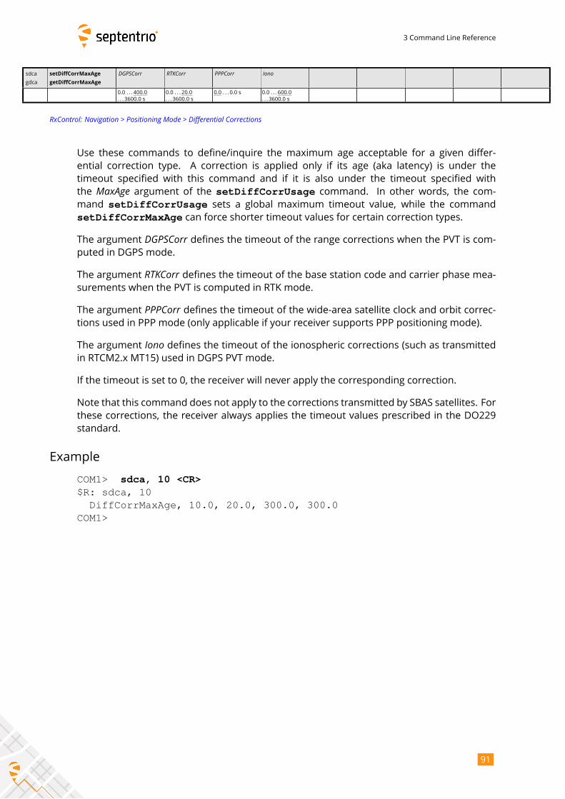
3 Command Line Reference
sdca
gdca
setDiffCorrMaxAge
getDiffCorrMaxAge
DGPSCorr RTKCorr PPPCorr Iono
0.0 . . . 400.0
. . . 3600.0 s
0.0 . . . 20.0
. . . 3600.0 s
0.0 . . . 0.0 s 0.0 . . . 600.0
. . . 3600.0 s
RxControl: Navigation > Positioning Mode > Differential Corrections
Use these commands to define/inquire the maximum age acceptable for a given differ-
ential correction type. A correction is applied only if its age (aka latency) is under the
timeout specified with this command and if it is also under the timeout specified with
the MaxAge argument of the setDiffCorrUsage command. In other words, the com-
mand setDiffCorrUsage sets a global maximum timeout value, while the command
setDiffCorrMaxAge can force shorter timeout values for certain correction types.
The argument DGPSCorr defines the timeout of the range corrections when the PVT is com-puted in DGPS mode.
The argument RTKCorr defines the timeout of the base station code and carrier phase mea-surements when the PVT is computed in RTK mode.
The argument PPPCorr defines the timeout of the wide-area satellite clock and orbit correc-tions used in PPP mode (only applicable if your receiver supports PPP positioning mode).
The argument Iono defines the timeout of the ionospheric corrections (such as transmittedin RTCM2.x MT15) used in DGPS PVT mode.
If the timeout is set to 0, the receiver will never apply the corresponding correction.
Note that this command does not apply to the corrections transmitted by SBAS satellites. For
these corrections, the receiver always applies the timeout values prescribed in the DO229
standard.
Example
COM1> sdca, 10 <CR>$R: sdca, 10DiffCorrMaxAge, 10.0, 20.0, 300.0, 300.0
COM1>
91
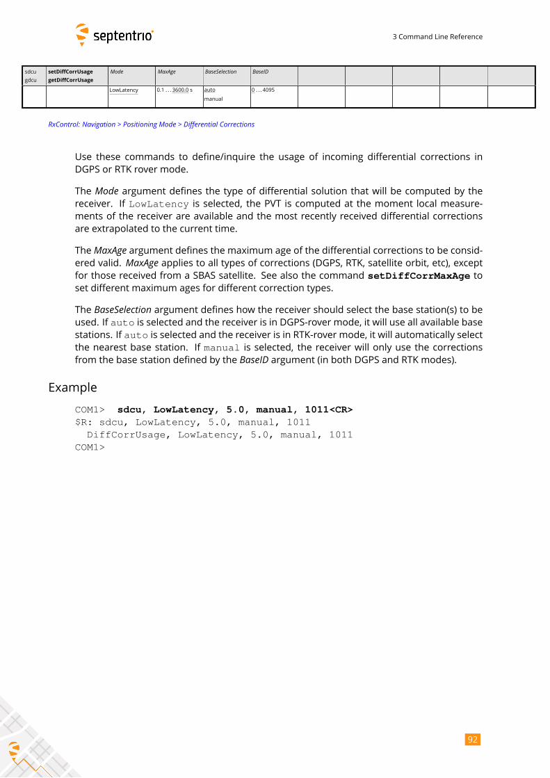
3 Command Line Reference
sdcu
gdcu
setDiffCorrUsage
getDiffCorrUsage
Mode MaxAge BaseSelection BaseID
LowLatency 0.1 . . . 3600.0 s auto
manual
0 . . . 4095
RxControl: Navigation > Positioning Mode > Differential Corrections
Use these commands to define/inquire the usage of incoming differential corrections in
DGPS or RTK rover mode.
The Mode argument defines the type of differential solution that will be computed by thereceiver. If LowLatency is selected, the PVT is computed at the moment local measure-ments of the receiver are available and the most recently received differential corrections
are extrapolated to the current time.
TheMaxAge argument defines the maximum age of the differential corrections to be consid-ered valid. MaxAge applies to all types of corrections (DGPS, RTK, satellite orbit, etc), exceptfor those received from a SBAS satellite. See also the command setDiffCorrMaxAge toset different maximum ages for different correction types.
The BaseSelection argument defines how the receiver should select the base station(s) to beused. If auto is selected and the receiver is in DGPS-rover mode, it will use all available basestations. If auto is selected and the receiver is in RTK-rover mode, it will automatically selectthe nearest base station. If manual is selected, the receiver will only use the correctionsfrom the base station defined by the BaseID argument (in both DGPS and RTK modes).
Example
COM1> sdcu, LowLatency, 5.0, manual, 1011<CR>$R: sdcu, LowLatency, 5.0, manual, 1011
DiffCorrUsage, LowLatency, 5.0, manual, 1011COM1>
92
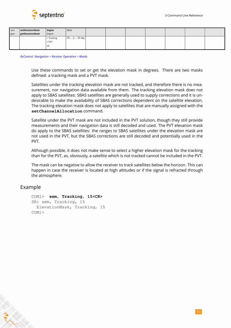
3 Command Line Reference
sem
gem
setElevationMask
getElevationMask
EngineEngine
Mask
+ Tracking
+ PVT
all
-90 . . . 0 . . . 90 deg
RxControl: Navigation > Receiver Operation > Masks
Use these commands to set or get the elevation mask in degrees. There are two masks
defined: a tracking mask and a PVT mask.
Satellites under the tracking elevation mask are not tracked, and therefore there is no mea-
surement, nor navigation data available from them. The tracking elevation mask does not
apply to SBAS satellites: SBAS satellites are generally used to supply corrections and it is un-
desirable to make the availability of SBAS corrections dependent on the satellite elevation.
The tracking elevation mask does not apply to satellites that are manually assigned with the
setChannelAllocation command.
Satellite under the PVT mask are not included in the PVT solution, though they still provide
measurements and their navigation data is still decoded and used. The PVT elevation mask
do apply to the SBAS satellites: the ranges to SBAS satellites under the elevation mask are
not used in the PVT, but the SBAS corrections are still decoded and potentially used in the
PVT.
Although possible, it does not make sense to select a higher elevation mask for the tracking
than for the PVT, as, obviously, a satellite which is not tracked cannot be included in the PVT.
The mask can be negative to allow the receiver to track satellites below the horizon. This can
happen in case the receiver is located at high altitudes or if the signal is refracted through
the atmosphere.
Example
COM1> sem, Tracking, 15<CR>$R: sem, Tracking, 15
ElevationMask, Tracking, 15COM1>
93
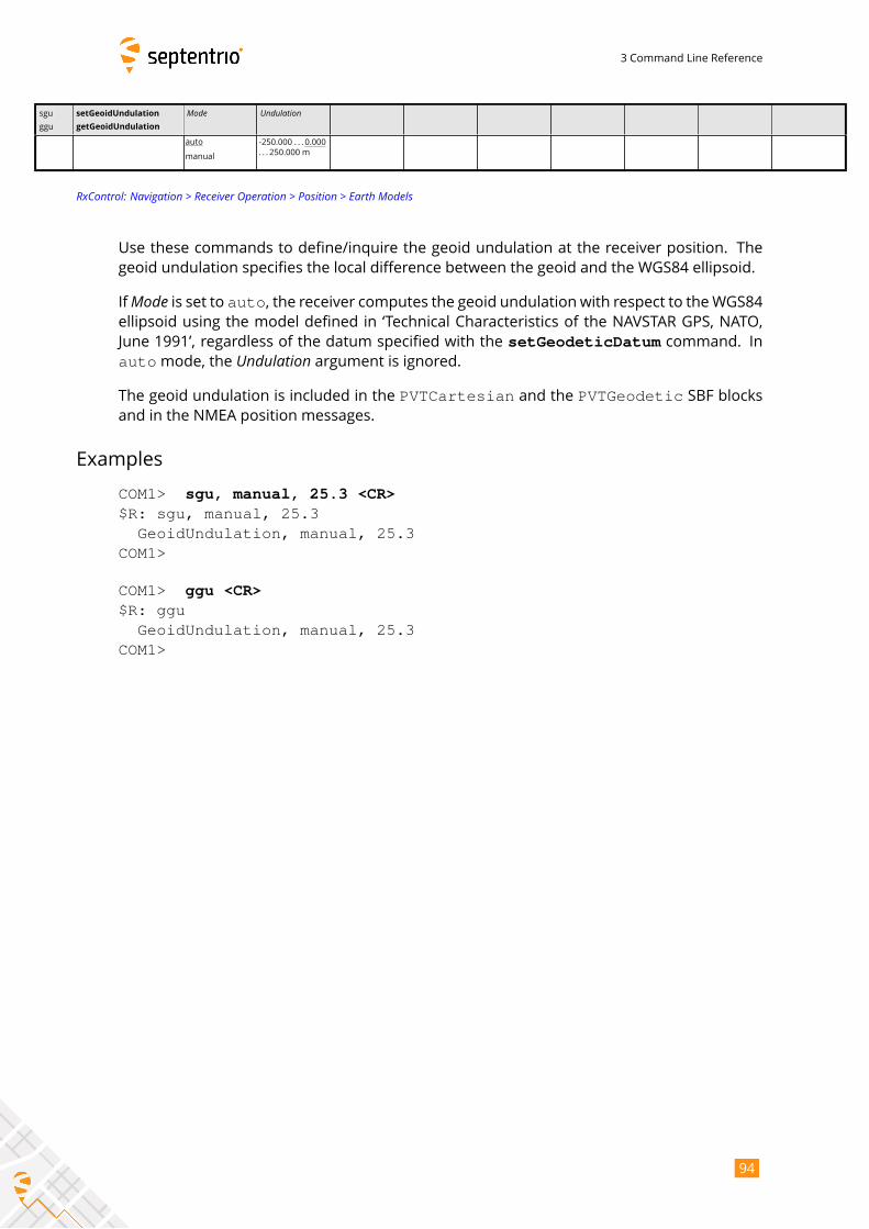
3 Command Line Reference
sgu
ggu
setGeoidUndulation
getGeoidUndulation
Mode Undulation
auto
manual
-250.000 . . . 0.000
. . . 250.000 m
RxControl: Navigation > Receiver Operation > Position > Earth Models
Use these commands to define/inquire the geoid undulation at the receiver position. The
geoid undulation specifies the local difference between the geoid and the WGS84 ellipsoid.
IfMode is set to auto, the receiver computes the geoid undulation with respect to theWGS84ellipsoid using the model defined in ‘Technical Characteristics of the NAVSTAR GPS, NATO,
June 1991’, regardless of the datum specified with the setGeodeticDatum command. Inautomode, the Undulation argument is ignored.The geoid undulation is included in the PVTCartesian and the PVTGeodetic SBF blocksand in the NMEA position messages.
Examples
COM1> sgu, manual, 25.3 <CR>$R: sgu, manual, 25.3
GeoidUndulation, manual, 25.3COM1>
COM1> ggu <CR>$R: ggu
GeoidUndulation, manual, 25.3COM1>
94
3 Command Line Reference
shm
ghm
setHealthMask
getHealthMask
EngineEngine
Mask
+ Tracking
+ PVT
all
off
on
RxControl: Navigation > Receiver Operation > Masks
Use these commands to define/inquire whether measurements should be produced for un-
healthy satellite signals, and whether these measurements should be included in the PVT
solution. All satellite signals of which the health is unknown to the receiver (because the
health information has not been decoded yet or is not transmitted) are considered healthy.
If Mask is on for the Tracking engine, no measurements are generated for unhealthy sig-nals, but these signals will remain internally tracked and their navigation data will be decoded
and processed. This is to ensure immediate reaction in the event that the signal would be-
come healthy again.
If Mask is on for the PVT engine, measurements from unhealthy signals are not included inthe PVT. Setting this mask to offmust be done with caution: including a non-healthy signalin the PVT computation may lead to unpredictable behaviour of the receiver.
Although possible, it does not make sense to enable unhealthy satellites for the PVT if they
are disabled for tracking.
Examples
To track unhealthy satellites/signals, use:
COM1> shm, Tracking, off <CR>$R: shm, Tracking, off
HealthMask, Tracking, offCOM1>
COM1> ghm <CR>$R: ghm
HealthMask, Tracking, offHealthMask, PVT, on
COM1>
95
3 Command Line Reference
sim
gim
setIonosphereModel
getIonosphereModel
Model
auto
off
Klobuchar
SBAS
MultiFreq
KlobucharBeiDou
RxControl: Navigation > Receiver Operation > Position > Atmosphere
Use these commands to define/inquire the type of model used to correct ionospheric errors
in the PVT computation. The following models are available:
Model Description
auto With this selection, the receiver will, based on the available
information, automatically select the best model on a satellite
to satellite basis.
off The receiver will not correct measurements for the
ionospheric delay. This may be desirable if the receiver is
connected to a GNSS signal simulator.
Klobuchar This model uses the parameters as transmitted by the GPS
satellites to compute the ionospheric delays.
SBAS This model complies with the DO229 standard: it uses the
near real-time ionospheric delays transmitted by the SBAS
satellites in MT18 and MT26. If no such message has been
received, the Klobucharmodel is selected automatically.
MultiFreq This model uses a combination of measurements on different
carriers to accurately estimate ionospheric delays. It requires
the availability of at least dual-frequency measurements.
KlobucharBeiDou This model uses the parameters as transmitted by the BeiDou
satellites to compute the ionospheric delays.
Unless the model is set to auto, the receiver uses the samemodel for all satellites, e.g. if theKlobucharmodel is requested, the Klobuchar parameters transmitted by GPS satellites areused for all tracked satellites, regardless of their constellation.
If not enough data is available to apply the prescribed model to a given satellite (for instance
if only single-frequency measurements are available and the model is set to MultiFreq),the satellite in question will be discarded from the PVT. Under most circumstances, it is rec-
ommended to leave the model to auto.
Examples
To disable the compensation for ionospheric delays, use:
COM1> sim, off <CR>$R: sim, off
IonosphereModel, offCOM1>
COM1> gim <CR>$R: gim
96

3 Command Line Reference
IonosphereModel, offCOM1>
97
3 Command Line Reference
smv
gmv
setMagneticVariance
getMagneticVariance
Mode Variation
auto
manual
-180.0 . . . 0.0
. . . 180.0 deg
RxControl: Navigation > Receiver Operation > Position > Earth Models
Use these commands to define the magnetic variation (a.k.a. magnetic declination) at the
current position. The magnetic variation specifies the local offset of the direction to the
magnetic north with respect to the geographic north. The variation is positive when the
magnetic north is east of the geographic north.
By default (the argumentMode is set to auto), the receiver automatically computes the vari-ation according to the 12th generation of the International Geomagnetic Reference Field
(IGRF) model, using the IGRF2015 coefficients corrected for the secular variation.
Note that the magnetic variation is used solely in the generation of NMEA messages.
Examples
COM1> smv, manual, 1.1 <CR>$R: smv, manual, 1.1
MagneticVariance, manual, 1.1COM1>
COM1> gmv <CR>$R: gmv
MagneticVariance, manual, 1.1COM1>
98
3 Command Line Reference
snrc
gnrc
setNetworkRTKConfig
getNetworkRTKConfig
NetworkType
auto
VRS
RxControl: Navigation > Positioning Mode > Differential Corrections
Use these commands to define/inquire the type of the RTK network providing the differential
corrections.
In most cases, it is recommended to leave the Type argument to auto to let the receiverautodetect the network type. For some types of VRS networks (especially for those having
long baselines between the base stations), optimal performance is obtained by forcing the
type to VRS.
Example
COM1> snrc, VRS <CR>$R: snrc, VRS
NetworkRTKConfig, VRSCOM1>
99
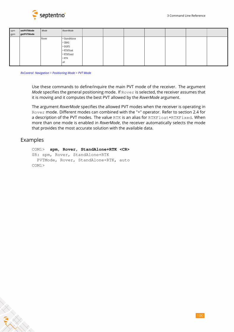
3 Command Line Reference
spm
gpm
setPVTMode
getPVTMode
Mode RoverMode
Rover + StandAlone
+ SBAS
+DGPS
+RTKFloat
+ RTKFixed
+RTK
all
RxControl: Navigation > Positioning Mode > PVT Mode
Use these commands to define/inquire the main PVT mode of the receiver. The argumentMode specifies the general positioning mode. If Rover is selected, the receiver assumes thatit is moving and it computes the best PVT allowed by the RoverMode argument.The argument RoverMode specifies the allowed PVT modes when the receiver is operating inRovermode. Different modes can combined with the "+" operator. Refer to section 2.4 fora description of the PVT modes. The value RTK is an alias for RTKFloat+RTKFixed. Whenmore than one mode is enabled in RoverMode, the receiver automatically selects the modethat provides the most accurate solution with the available data.
Examples
COM1> spm, Rover, StandAlone+RTK <CR>$R: spm, Rover, StandAlone+RTK
PVTMode, Rover, StandAlone+RTK, autoCOM1>
100
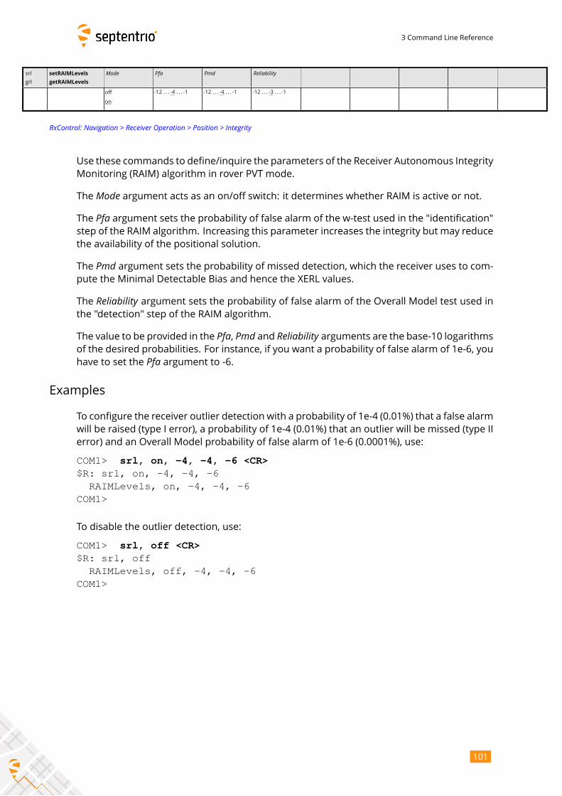
3 Command Line Reference
srl
grl
setRAIMLevels
getRAIMLevels
Mode Pfa Pmd Reliability
off
on
-12 . . . -4 . . . -1 -12 . . . -4 . . . -1 -12 . . . -3 . . . -1
RxControl: Navigation > Receiver Operation > Position > Integrity
Use these commands to define/inquire the parameters of the Receiver Autonomous Integrity
Monitoring (RAIM) algorithm in rover PVT mode.
The Mode argument acts as an on/off switch: it determines whether RAIM is active or not.The Pfa argument sets the probability of false alarm of the w-test used in the "identification"step of the RAIM algorithm. Increasing this parameter increases the integrity but may reduce
the availability of the positional solution.
The Pmd argument sets the probability of missed detection, which the receiver uses to com-pute the Minimal Detectable Bias and hence the XERL values.
The Reliability argument sets the probability of false alarm of the Overall Model test used inthe "detection" step of the RAIM algorithm.
The value to be provided in the Pfa, Pmd and Reliability arguments are the base-10 logarithmsof the desired probabilities. For instance, if you want a probability of false alarm of 1e-6, you
have to set the Pfa argument to -6.Examples
To configure the receiver outlier detection with a probability of 1e-4 (0.01%) that a false alarm
will be raised (type I error), a probability of 1e-4 (0.01%) that an outlier will be missed (type II
error) and an Overall Model probability of false alarm of 1e-6 (0.0001%), use:
COM1> srl, on, -4, -4, -6 <CR>$R: srl, on, -4, -4, -6
RAIMLevels, on, -4, -4, -6COM1>
To disable the outlier detection, use:
COM1> srl, off <CR>$R: srl, off
RAIMLevels, off, -4, -4, -6COM1>
101
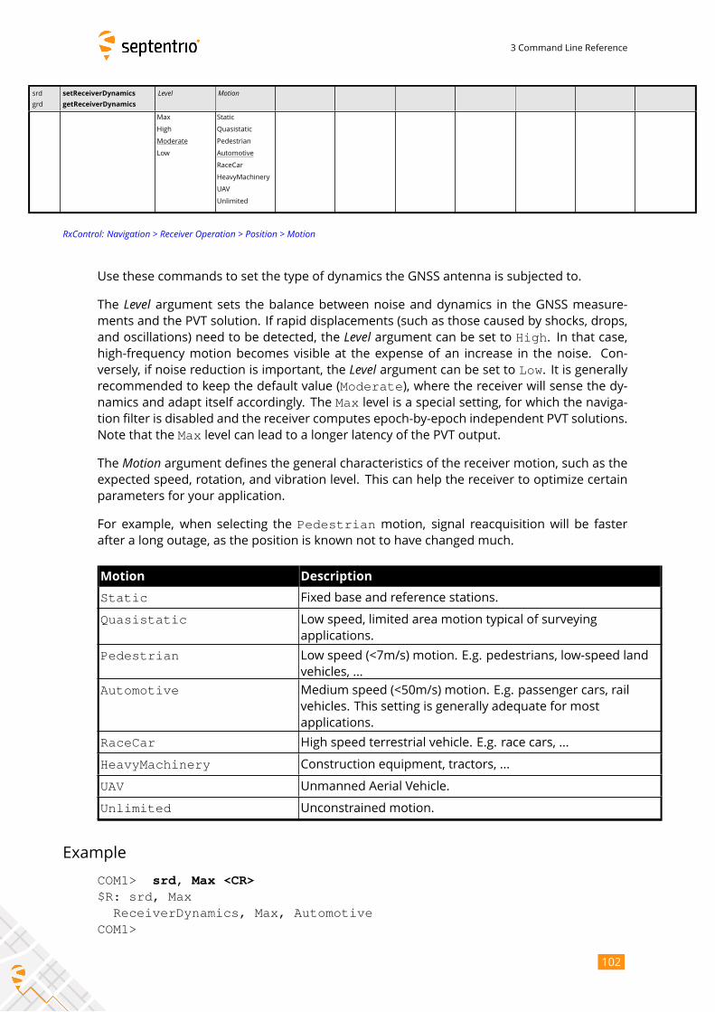
3 Command Line Reference
srd
grd
setReceiverDynamics
getReceiverDynamics
Level Motion
Max
High
Moderate
Low
Static
Quasistatic
Pedestrian
Automotive
RaceCar
HeavyMachinery
UAV
Unlimited
RxControl: Navigation > Receiver Operation > Position > Motion
Use these commands to set the type of dynamics the GNSS antenna is subjected to.
The Level argument sets the balance between noise and dynamics in the GNSS measure-ments and the PVT solution. If rapid displacements (such as those caused by shocks, drops,
and oscillations) need to be detected, the Level argument can be set to High. In that case,high-frequency motion becomes visible at the expense of an increase in the noise. Con-
versely, if noise reduction is important, the Level argument can be set to Low. It is generallyrecommended to keep the default value (Moderate), where the receiver will sense the dy-namics and adapt itself accordingly. The Max level is a special setting, for which the naviga-tion filter is disabled and the receiver computes epoch-by-epoch independent PVT solutions.
Note that the Max level can lead to a longer latency of the PVT output.
The Motion argument defines the general characteristics of the receiver motion, such as theexpected speed, rotation, and vibration level. This can help the receiver to optimize certain
parameters for your application.
For example, when selecting the Pedestrian motion, signal reacquisition will be fasterafter a long outage, as the position is known not to have changed much.
Motion Description
Static Fixed base and reference stations.
Quasistatic Low speed, limited area motion typical of surveying
applications.
Pedestrian Low speed (<7m/s) motion. E.g. pedestrians, low-speed land
vehicles, ...
Automotive Medium speed (<50m/s) motion. E.g. passenger cars, rail
vehicles. This setting is generally adequate for most
applications.
RaceCar High speed terrestrial vehicle. E.g. race cars, ...
HeavyMachinery Construction equipment, tractors, ...
UAV Unmanned Aerial Vehicle.
Unlimited Unconstrained motion.
Example
COM1> srd, Max <CR>$R: srd, Max
ReceiverDynamics, Max, AutomotiveCOM1>
102
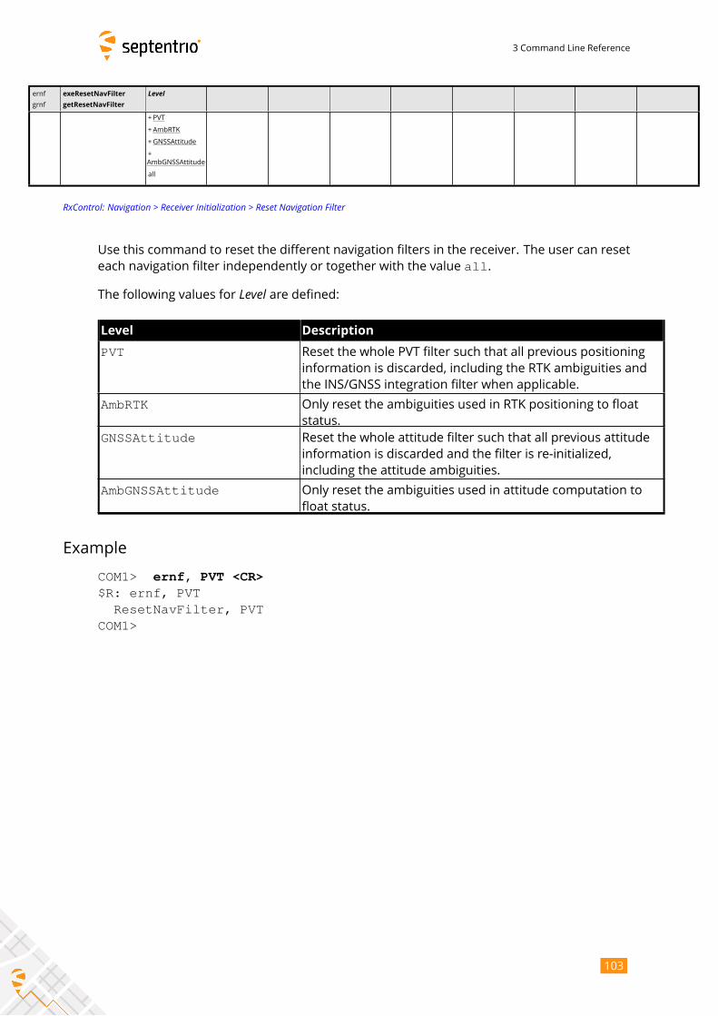
3 Command Line Reference
ernf
grnf
exeResetNavFilter
getResetNavFilter
Level
+PVT
+AmbRTK
+GNSSAttitude
+
AmbGNSSAttitude
all
RxControl: Navigation > Receiver Initialization > Reset Navigation Filter
Use this command to reset the different navigation filters in the receiver. The user can reset
each navigation filter independently or together with the value all.
The following values for Level are defined:Level Description
PVT Reset the whole PVT filter such that all previous positioning
information is discarded, including the RTK ambiguities and
the INS/GNSS integration filter when applicable.
AmbRTK Only reset the ambiguities used in RTK positioning to float
status.
GNSSAttitude Reset the whole attitude filter such that all previous attitude
information is discarded and the filter is re-initialized,
including the attitude ambiguities.
AmbGNSSAttitude Only reset the ambiguities used in attitude computation to
float status.
Example
COM1> ernf, PVT <CR>$R: ernf, PVT
ResetNavFilter, PVTCOM1>
103
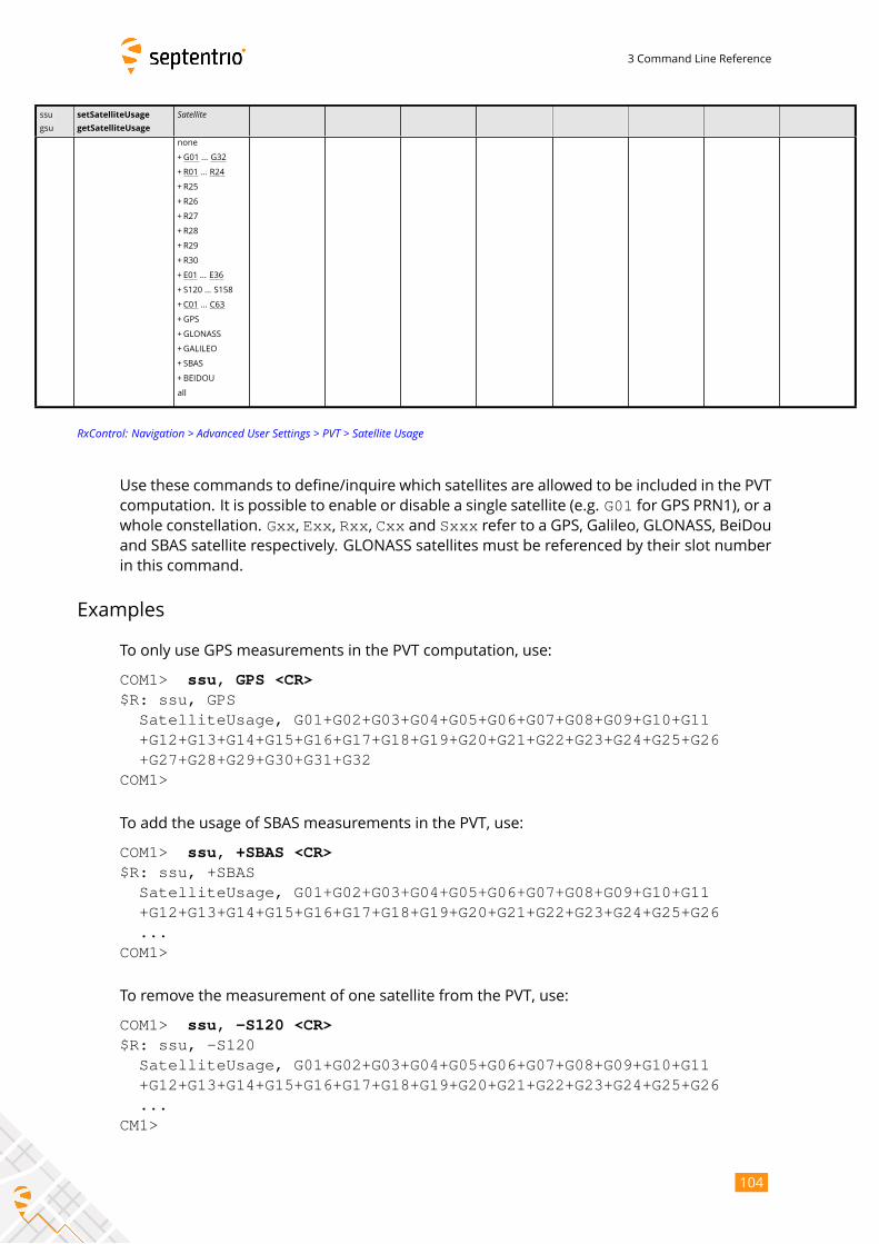
3 Command Line Reference
ssu
gsu
setSatelliteUsage
getSatelliteUsage
Satellitenone
+G01 ... G32
+R01 ... R24
+R25
+R26
+R27
+R28
+R29
+R30
+ E01 ... E36
+ S120 ... S158
+C01 ... C63
+GPS
+GLONASS
+GALILEO
+ SBAS
+BEIDOU
all
RxControl: Navigation > Advanced User Settings > PVT > Satellite Usage
Use these commands to define/inquire which satellites are allowed to be included in the PVT
computation. It is possible to enable or disable a single satellite (e.g. G01 for GPS PRN1), or awhole constellation. Gxx, Exx, Rxx, Cxx and Sxxx refer to a GPS, Galileo, GLONASS, BeiDouand SBAS satellite respectively. GLONASS satellites must be referenced by their slot number
in this command.
Examples
To only use GPS measurements in the PVT computation, use:
COM1> ssu, GPS <CR>$R: ssu, GPS
SatelliteUsage, G01+G02+G03+G04+G05+G06+G07+G08+G09+G10+G11+G12+G13+G14+G15+G16+G17+G18+G19+G20+G21+G22+G23+G24+G25+G26+G27+G28+G29+G30+G31+G32
COM1>
To add the usage of SBAS measurements in the PVT, use:
COM1> ssu, +SBAS <CR>$R: ssu, +SBAS
SatelliteUsage, G01+G02+G03+G04+G05+G06+G07+G08+G09+G10+G11+G12+G13+G14+G15+G16+G17+G18+G19+G20+G21+G22+G23+G24+G25+G26...
COM1>
To remove the measurement of one satellite from the PVT, use:
COM1> ssu, -S120 <CR>$R: ssu, -S120
SatelliteUsage, G01+G02+G03+G04+G05+G06+G07+G08+G09+G10+G11+G12+G13+G14+G15+G16+G17+G18+G19+G20+G21+G22+G23+G24+G25+G26...
CM1>
104
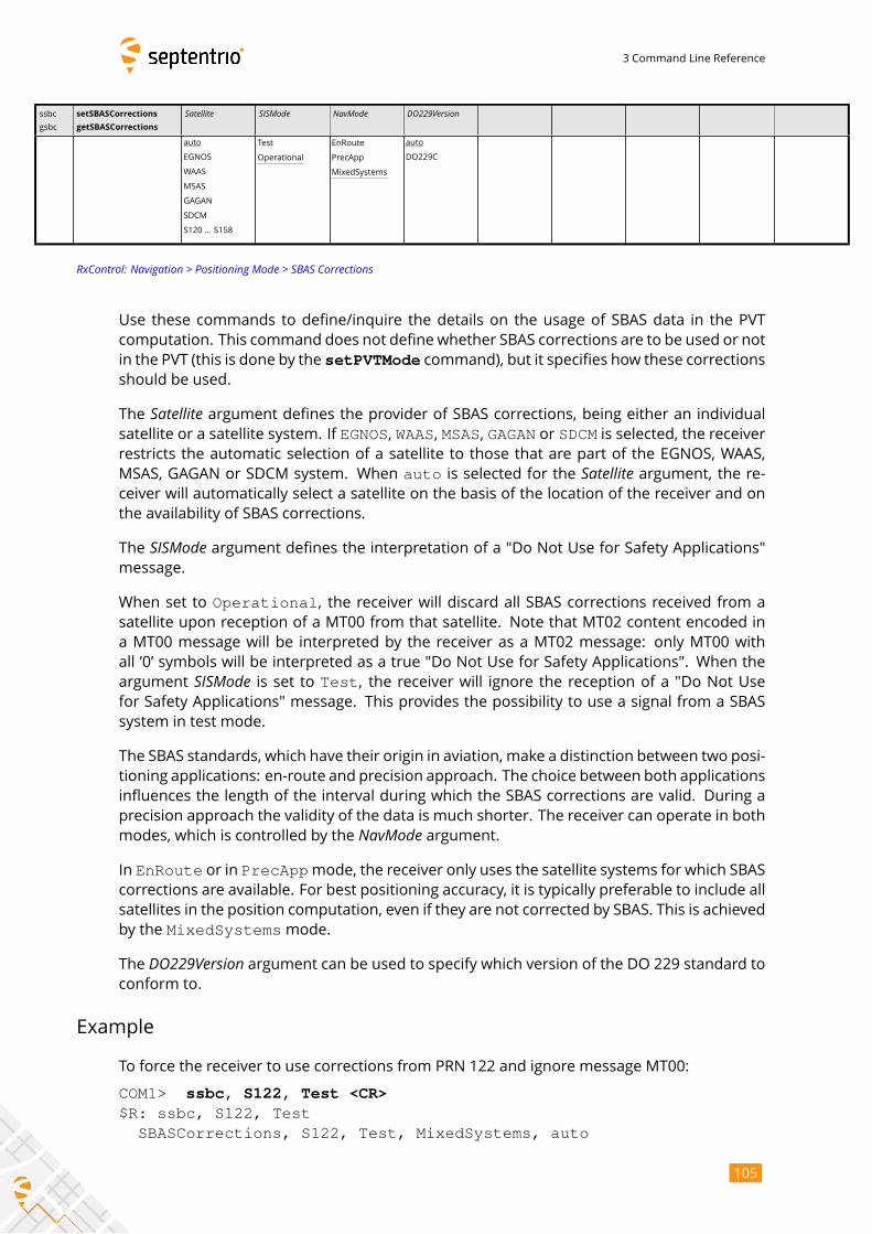
3 Command Line Reference
ssbc
gsbc
setSBASCorrections
getSBASCorrections
Satellite SISMode NavMode DO229Version
auto
EGNOS
WAAS
MSAS
GAGAN
SDCM
S120 ... S158
Test
Operational
EnRoute
PrecApp
MixedSystems
auto
DO229C
RxControl: Navigation > Positioning Mode > SBAS Corrections
Use these commands to define/inquire the details on the usage of SBAS data in the PVT
computation. This command does not define whether SBAS corrections are to be used or not
in the PVT (this is done by the setPVTMode command), but it specifies how these correctionsshould be used.
The Satellite argument defines the provider of SBAS corrections, being either an individualsatellite or a satellite system. If EGNOS, WAAS, MSAS, GAGAN or SDCM is selected, the receiverrestricts the automatic selection of a satellite to those that are part of the EGNOS, WAAS,
MSAS, GAGAN or SDCM system. When auto is selected for the Satellite argument, the re-ceiver will automatically select a satellite on the basis of the location of the receiver and on
the availability of SBAS corrections.
The SISMode argument defines the interpretation of a "Do Not Use for Safety Applications"message.
When set to Operational, the receiver will discard all SBAS corrections received from asatellite upon reception of a MT00 from that satellite. Note that MT02 content encoded in
a MT00 message will be interpreted by the receiver as a MT02 message: only MT00 with
all ’0’ symbols will be interpreted as a true "Do Not Use for Safety Applications". When the
argument SISMode is set to Test, the receiver will ignore the reception of a "Do Not Usefor Safety Applications" message. This provides the possibility to use a signal from a SBAS
system in test mode.
The SBAS standards, which have their origin in aviation, make a distinction between two posi-
tioning applications: en-route and precision approach. The choice between both applications
influences the length of the interval during which the SBAS corrections are valid. During a
precision approach the validity of the data is much shorter. The receiver can operate in both
modes, which is controlled by the NavMode argument.In EnRoute or in PrecAppmode, the receiver only uses the satellite systems for which SBAScorrections are available. For best positioning accuracy, it is typically preferable to include all
satellites in the position computation, even if they are not corrected by SBAS. This is achieved
by the MixedSystemsmode.
The DO229Version argument can be used to specify which version of the DO 229 standard toconform to.
Example
To force the receiver to use corrections from PRN 122 and ignore message MT00:
COM1> ssbc, S122, Test <CR>$R: ssbc, S122, Test
SBASCorrections, S122, Test, MixedSystems, auto
105

3 Command Line Reference
COM1>
106
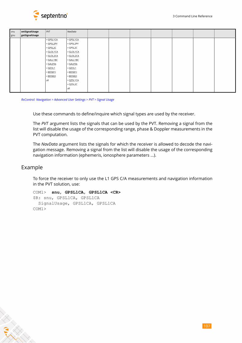
3 Command Line Reference
snu
gnu
setSignalUsage
getSignalUsage
PVT NavData
+GPSL1CA
+GPSL2PY
+GPSL2C
+GLOL1CA
+GLOL2CA
+GALL1BC
+GALE5b
+GEOL1
+BDSB1I
+BDSB2I
all
+GPSL1CA
+GPSL2PY
+GPSL2C
+GLOL1CA
+GLOL2CA
+GALL1BC
+GALE5b
+GEOL1
+BDSB1I
+BDSB2I
+QZSL1CA
+QZSL2C
all
RxControl: Navigation > Advanced User Settings > PVT > Signal Usage
Use these commands to define/inquire which signal types are used by the receiver.
The PVT argument lists the signals that can be used by the PVT. Removing a signal from thelist will disable the usage of the corresponding range, phase & Doppler measurements in the
PVT computation.
The NavData argument lists the signals for which the receiver is allowed to decode the navi-gation message. Removing a signal from the list will disable the usage of the corresponding
navigation information (ephemeris, ionosphere parameters ...).
Example
To force the receiver to only use the L1 GPS C/A measurements and navigation information
in the PVT solution, use:
COM1> snu, GPSL1CA, GPSL1CA <CR>$R: snu, GPSL1CA, GPSL1CA
SignalUsage, GPSL1CA, GPSL1CACOM1>
107
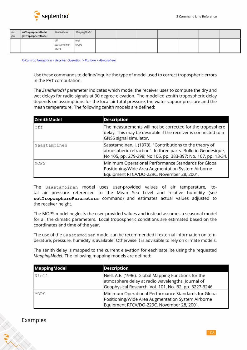
3 Command Line Reference
stm
gtm
setTroposphereModel
getTroposphereModel
ZenithModel MappingModel
off
Saastamoinen
MOPS
Niell
MOPS
RxControl: Navigation > Receiver Operation > Position > Atmosphere
Use these commands to define/inquire the type of model used to correct tropospheric errors
in the PVT computation.
The ZenithModel parameter indicates which model the receiver uses to compute the dry andwet delays for radio signals at 90 degree elevation. The modelled zenith tropospheric delay
depends on assumptions for the local air total pressure, the water vapour pressure and the
mean temperature. The following zenith models are defined:
ZenithModel Description
off The measurements will not be corrected for the troposphere
delay. This may be desirable if the receiver is connected to a
GNSS signal simulator.
Saastamoinen Saastamoinen, J. (1973). "Contributions to the theory of
atmospheric refraction". In three parts. Bulletin Geodesique,
No 105, pp. 279-298; No 106, pp. 383-397; No. 107, pp. 13-34.
MOPS Minimum Operational Performance Standards for Global
Positioning/Wide Area Augmentation System Airborne
Equipment RTCA/DO-229C, November 28, 2001.
The Saastamoinen model uses user-provided values of air temperature, to-
tal air pressure referenced to the Mean Sea Level and relative humidity (see
setTroposphereParameters command) and estimates actual values adjusted to
the receiver height.
The MOPS model neglects the user-provided values and instead assumes a seasonal model
for all the climatic parameters. Local tropospheric conditions are estimated based on the
coordinates and time of the year.
The use of the Saastamoinenmodel can be recommended if external information on tem-perature, pressure, humidity is available. Otherwise it is advisable to rely on climate models.
The zenith delay is mapped to the current elevation for each satellite using the requestedMappingModel. The following mapping models are defined:MappingModel Description
Niell Niell, A.E. (1996). Global Mapping Functions for the
atmosphere delay at radio wavelengths, Journal of
Geophysical Research, Vol. 101, No. B2, pp. 3227-3246.
MOPS Minimum Operational Performance Standards for Global
Positioning/Wide Area Augmentation System Airborne
Equipment RTCA/DO-229C, November 28, 2001.
Examples
108
3 Command Line Reference
COM1> stm, MOPS, MOPS <CR>$R: stm, MOPS, MOPS
TroposhereModel, MOPS, MOPSCOM1>
COM1> gtm <CR>$R: gtm
TroposhereModel, MOPS, MOPSCOM1>
109
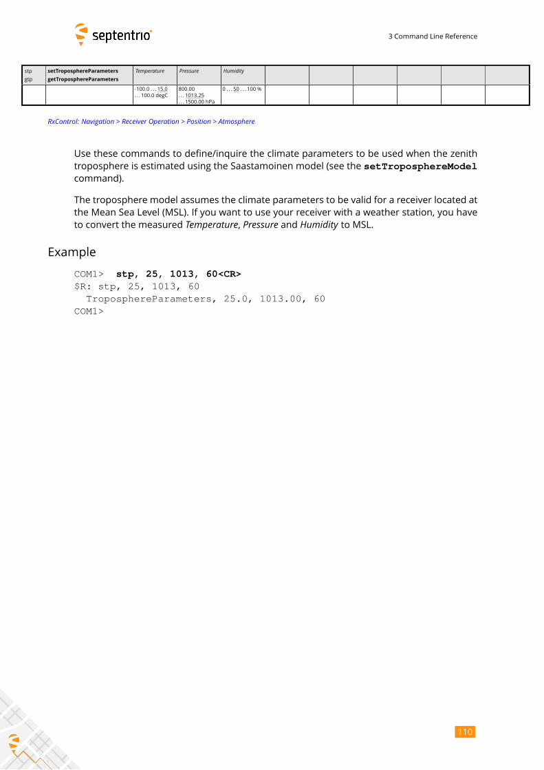
3 Command Line Reference
stp
gtp
setTroposphereParameters
getTroposphereParameters
Temperature Pressure Humidity
-100.0 . . . 15.0
. . . 100.0 degC
800.00
. . . 1013.25
. . . 1500.00 hPa
0 . . . 50 . . . 100 %
RxControl: Navigation > Receiver Operation > Position > Atmosphere
Use these commands to define/inquire the climate parameters to be used when the zenith
troposphere is estimated using the Saastamoinen model (see the setTroposphereModelcommand).
The troposphere model assumes the climate parameters to be valid for a receiver located at
the Mean Sea Level (MSL). If you want to use your receiver with a weather station, you have
to convert the measured Temperature, Pressure and Humidity to MSL.Example
COM1> stp, 25, 1013, 60<CR>$R: stp, 25, 1013, 60
TroposphereParameters, 25.0, 1013.00, 60COM1>
110

3 Command Line Reference
3.2.7 Attitude Determination
sal
gal
setAntennaLocation
getAntennaLocation
AntennaAntenna
Mode DeltaX DeltaY DeltaZ
+Aux1
all
auto
manual
-1000.0000
. . . 0.0000
. . . 1000.0000 m
-1000.0000
. . . 0.0000
. . . 1000.0000 m
-1000.0000
. . . 0.0000
. . . 1000.0000 m
RxControl: Navigation > Positioning Mode > GNSS Attitude
Use this command to define/inquire the relative location of the antennas in the vehicle ref-
erence frame in the context of attitude determination. See appendix A for a description of
the vehicle reference frame.
The attitude of a vehicle (more precisely the heading and pitch angles) can be determined
from the orientation of the baseline between two antennas attached to the vehicle. These
two antennas must be connected to a single multi-antenna receiver (multi-antenna attitude).
Use the command setGNSSAttitude to enable attitude determination.
In multi-antenna attitude, Antenna should be set to Aux1 to specify the relative position ofthe aux1 antenna with respect to the main antenna.
In auto mode, the receiver determines the attitude angles assuming that the baseline be-tween the antenna ARPs is parallel to the longitudinal axis of the vehicle, and that the aux1
antenna is in front of the main antenna (i.e. towards the direction of movement). The length
of the baseline is automatically computed by the receiver, and the baseline may be flexible.
The DeltaX , DeltaY and DeltaZ arguments are ignored in automode.In manualmode, the user can specify the exact position of the aux1 antenna with respect tothe main antenna in the vehicle reference frame. Selecting manual mode implies that thebaseline is rigid. The DeltaX , DeltaY and DeltaZ coordinates are ARP-to-ARP.
Example
In the case of moving-base attitude determination, if the moving-base antenna is located
one meter to the left of the rover antenna, and 10 cm below, you should use:
COM1> sal, Base, manual, 0, -1, 0.1 <CR>$R: sal, Base, manual, 0, 1, 0.1
AntennaLocation, Base, manual, 0.0000, -1.0000, 0.1000COM1>
111
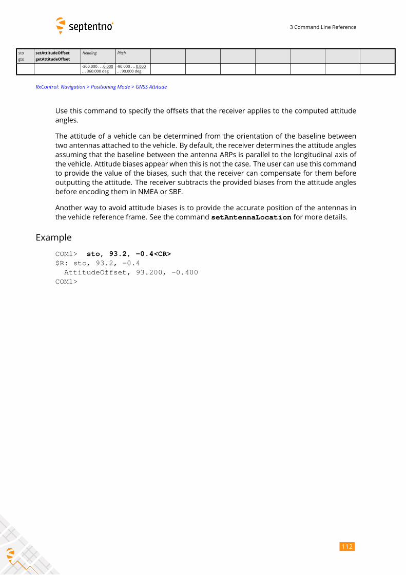
3 Command Line Reference
sto
gto
setAttitudeOffset
getAttitudeOffset
Heading Pitch
-360.000 . . . 0.000
. . . 360.000 deg
-90.000 . . . 0.000
. . . 90.000 deg
RxControl: Navigation > Positioning Mode > GNSS Attitude
Use this command to specify the offsets that the receiver applies to the computed attitude
angles.
The attitude of a vehicle can be determined from the orientation of the baseline between
two antennas attached to the vehicle. By default, the receiver determines the attitude angles
assuming that the baseline between the antenna ARPs is parallel to the longitudinal axis of
the vehicle. Attitude biases appear when this is not the case. The user can use this command
to provide the value of the biases, such that the receiver can compensate for them before
outputting the attitude. The receiver subtracts the provided biases from the attitude angles
before encoding them in NMEA or SBF.
Another way to avoid attitude biases is to provide the accurate position of the antennas in
the vehicle reference frame. See the command setAntennaLocation for more details.
Example
COM1> sto, 93.2, -0.4<CR>$R: sto, 93.2, -0.4
AttitudeOffset, 93.200, -0.400COM1>
112
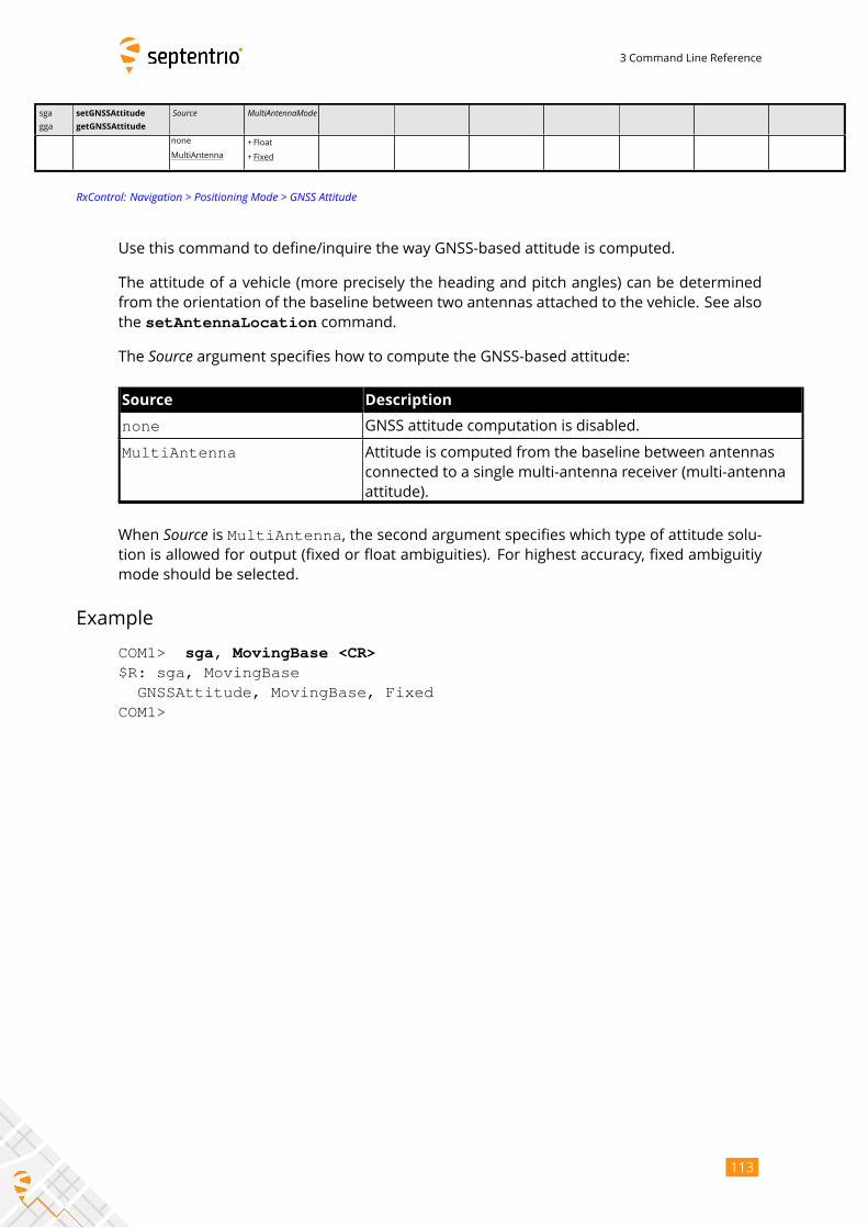
3 Command Line Reference
sga
gga
setGNSSAttitude
getGNSSAttitude
Source MultiAntennaModenone
MultiAntenna
+ Float
+ Fixed
RxControl: Navigation > Positioning Mode > GNSS Attitude
Use this command to define/inquire the way GNSS-based attitude is computed.
The attitude of a vehicle (more precisely the heading and pitch angles) can be determined
from the orientation of the baseline between two antennas attached to the vehicle. See also
the setAntennaLocation command.
The Source argument specifies how to compute the GNSS-based attitude:Source Description
none GNSS attitude computation is disabled.
MultiAntenna Attitude is computed from the baseline between antennas
connected to a single multi-antenna receiver (multi-antenna
attitude).
When Source is MultiAntenna, the second argument specifies which type of attitude solu-tion is allowed for output (fixed or float ambiguities). For highest accuracy, fixed ambiguitiy
mode should be selected.
Example
COM1> sga, MovingBase <CR>$R: sga, MovingBase
GNSSAttitude, MovingBase, FixedCOM1>
113

3 Command Line Reference
3.2.8 Datum Definition
sgd
ggd
setGeodeticDatum
getGeodeticDatum
TargetDatum
WGS84
ETRS89
NAD83
NAD83_PA
NAD83_MA
GDA94
GDA2020
Default
User1
User2
RxControl: Navigation > Receiver Operation > Position > Datum
Use this command to define the datum to which you want the coordinates to refer.
TargetDatum Description
WGS84 Equivalent to Default
ETRS89 European ETRS89 (ETRF2000 realization)
NAD83 NAD83(2011), North American Datum (2011)
NAD83_PA NAD83(PA11), North American Datum, Pacific plate (2011)
NAD83_MA NAD83(MA11), North American Datum, Marianas plate (2011)
GDA94 GDA94(2010), Geocentric Datum of Australia (2010)
GDA2020 GDA2020, Geocentric Datum of Australia 2020
Default Default datum, which depends on the positioning mode as
explained below except when a built-in local coordinate
operation is manually selected with the
setLocalCoordOperation command. In that case, thedatum is set accordingly to the selected coordinate operation.
User1 First user-defined datum. The corresponding transformation
parameters must be specified by the setUserDatum andsetUserDatumVel commands, while the correspondingellipsoid must be defined by the setUserEllipsoidcommand.
User2 Second user-defined datum
By default (argument TargetDatum set to Default), the datum depends on the positioningmode. For standalone and SBAS positioning, the coordinates refer to a global datum: WGS84
or ITRF (recent realisations of WGS84 and ITRF are closely aligned and the receiver consid-
ers them equivalent). When using DGNSS or RTK corrections from a regional DGNSS/RTK
provider, the coordinates usually refer to a regional datum (e.g. ETRS89 in Europe or NAD83
in North America).
With this command, the user can select the datum the coordinates should refer to. In case
you are using corrections from a regional DGNSS/RTK provider, the datum to be specified
here must be the datum used by your correction provider.
114
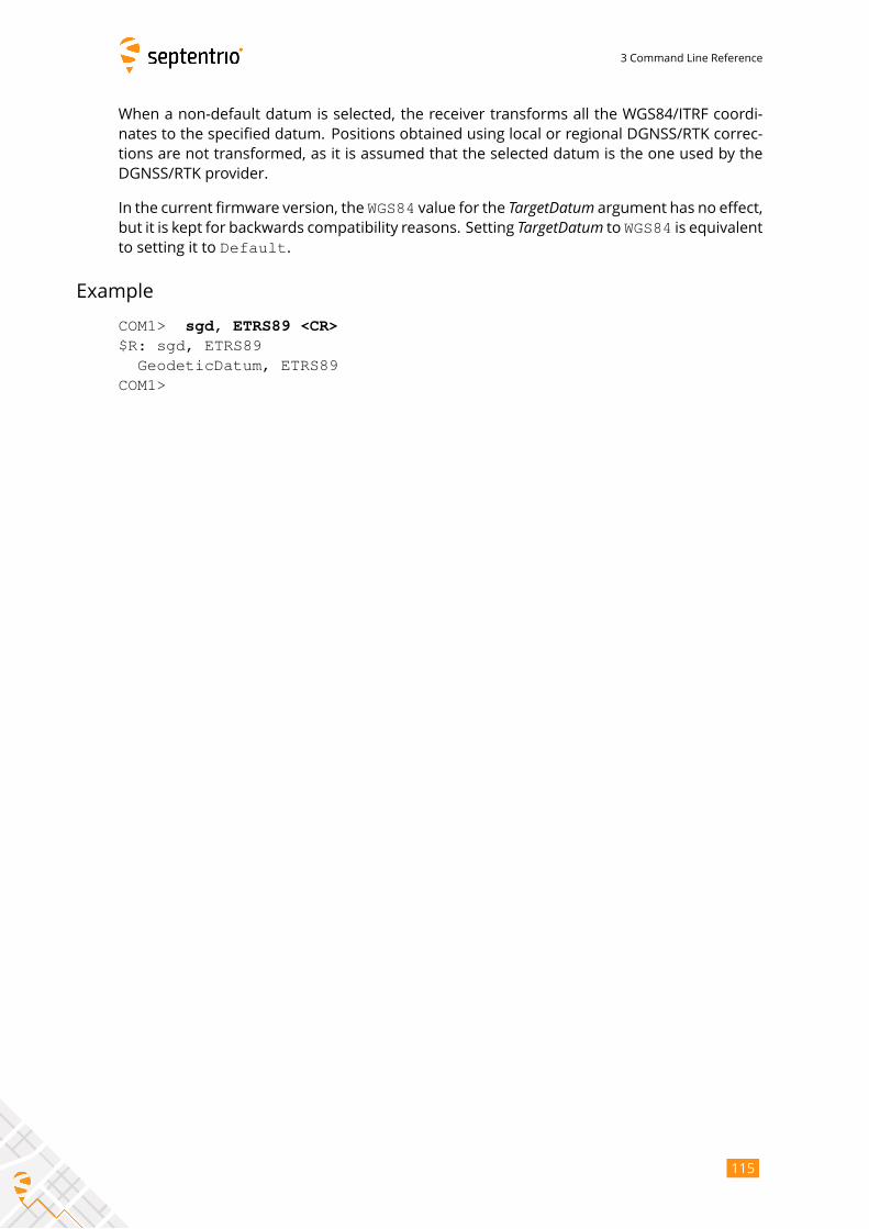
3 Command Line Reference
When a non-default datum is selected, the receiver transforms all the WGS84/ITRF coordi-
nates to the specified datum. Positions obtained using local or regional DGNSS/RTK correc-
tions are not transformed, as it is assumed that the selected datum is the one used by the
DGNSS/RTK provider.
In the current firmware version, the WGS84 value for the TargetDatum argument has no effect,but it is kept for backwards compatibility reasons. Setting TargetDatum to WGS84 is equivalentto setting it to Default.
Example
COM1> sgd, ETRS89 <CR>$R: sgd, ETRS89
GeodeticDatum, ETRS89COM1>
115
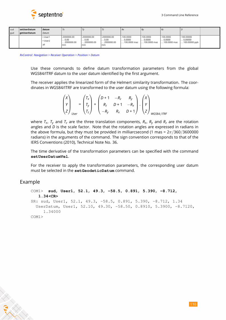
3 Command Line Reference
sud
gud
setUserDatum
getUserDatum
DatumDatum
Tx Ty Tz Rx Ry Rz D
+User1
+User2
all
-2000000.00
. . . 0.00
. . . 2000000.00
mm
-2000000.00
. . . 0.00
. . . 2000000.00
mm
-2000000.00
. . . 0.00
. . . 2000000.00
mm
-100.0000
. . . 0.0000
. . . 100.0000 mas
-100.0000
. . . 0.0000
. . . 100.0000 mas
-100.0000
. . . 0.0000
. . . 100.0000 mas
-100.00000
. . . 0.00000
. . . 100.00000 ppb
RxControl: Navigation > Receiver Operation > Position > Datum
Use these commands to define datum transformation parameters from the global
WGS84/ITRF datum to the user datum identified by the first argument.
The receiver applies the linearized form of the Helmert similarity transformation. The coor-
dinates in WGS84/ITRF are transformed to the user datum using the following formula:XYZ
User
=
TxTyTz
+D + 1 −Rz RyRz D + 1 −Rx−Ry Rx D + 1
.XYZ
WGS84/ITRF
where Tx, Ty and Tz are the three translation components, Rx, Ry and Rz are the rotationangles and D is the scale factor. Note that the rotation angles are expressed in radians inthe above formula, but they must be provided in milliarcsecond (1 mas = 2π/360/3600000radians) in the arguments of the command. The sign convention corresponds to that of the
IERS Conventions (2010), Technical Note No. 36.
The time derivative of the transformation parameters can be specified with the command
setUserDatumVel.
For the receiver to apply the transformation parameters, the corresponding user datum
must be selected in the setGeodeticDatum command.
Example
COM1> sud, User1, 52.1, 49.3, -58.5, 0.891, 5.390, -8.712,1.34<CR>
$R: sud, User1, 52.1, 49.3, -58.5, 0.891, 5.390, -8.712, 1.34UserDatum, User1, 52.10, 49.30, -58.50, 0.8910, 5.3900, -8.7120,
1.34000COM1>
116
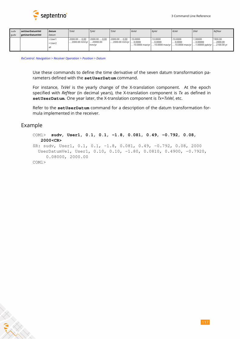
3 Command Line Reference
sudv
gudv
setUserDatumVel
getUserDatumVel
DatumDatum
TxVel TyVel TzVel RxVel RyVel RzVel DVel RefYear
+User1
+User2
all
-2000.00 . . . 0.00
. . . 2000.00 mm/yr
-2000.00 . . . 0.00
. . . 20000.00
mm/yr
-2000.00 . . . 0.00
. . . 2000.00 mm/yr
-10.0000
. . . 0.0000
. . . 10.0000 mas/yr
-10.0000
. . . 0.0000
. . . 10.0000 mas/yr
-10.0000
. . . 0.0000
. . . 10.0000 mas/yr
-1.00000
. . . 0.00000
. . . 1.00000 ppb/yr
1900.00
. . . 2000.00
. . . 2100.00 yr
RxControl: Navigation > Receiver Operation > Position > Datum
Use these commands to define the time derivative of the seven datum transformation pa-
rameters defined with the setUserDatum command.
For instance, TxVel is the yearly change of the X-translation component. At the epochspecified with RefYear (in decimal years), the X-translation component is Tx as defined insetUserDatum. One year later, the X-translation component is Tx+TxVel, etc.Refer to the setUserDatum command for a description of the datum transformation for-mula implemented in the receiver.
Example
COM1> sudv, User1, 0.1, 0.1, -1.8, 0.081, 0.49, -0.792, 0.08,2000<CR>
$R: sudv, User1, 0.1, 0.1, -1.8, 0.081, 0.49, -0.792, 0.08, 2000UserDatumVel, User1, 0.10, 0.10, -1.80, 0.0810, 0.4900, -0.7920,
0.08000, 2000.00COM1>
117
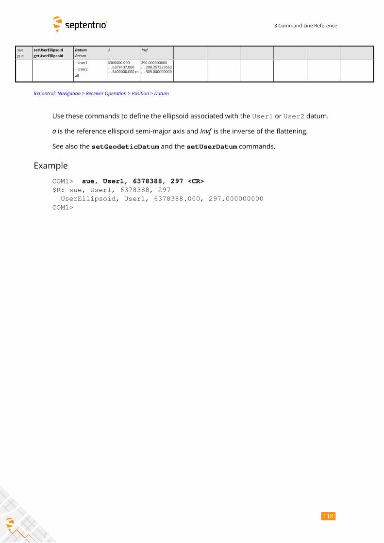
3 Command Line Reference
sue
gue
setUserEllipsoid
getUserEllipsoid
DatumDatum
A Invf
+User1
+User2
all
6300000.000
. . . 6378137.000
. . . 6400000.000 m
290.000000000
. . . 298.257223563
. . . 305.000000000
RxControl: Navigation > Receiver Operation > Position > Datum
Use these commands to define the ellipsoid associated with the User1 or User2 datum.
a is the reference ellispoid semi-major axis and Invf is the inverse of the flattening.See also the setGeodeticDatum and the setUserDatum commands.
Example
COM1> sue, User1, 6378388, 297 <CR>$R: sue, User1, 6378388, 297
UserEllipsoid, User1, 6378388.000, 297.000000000COM1>
118
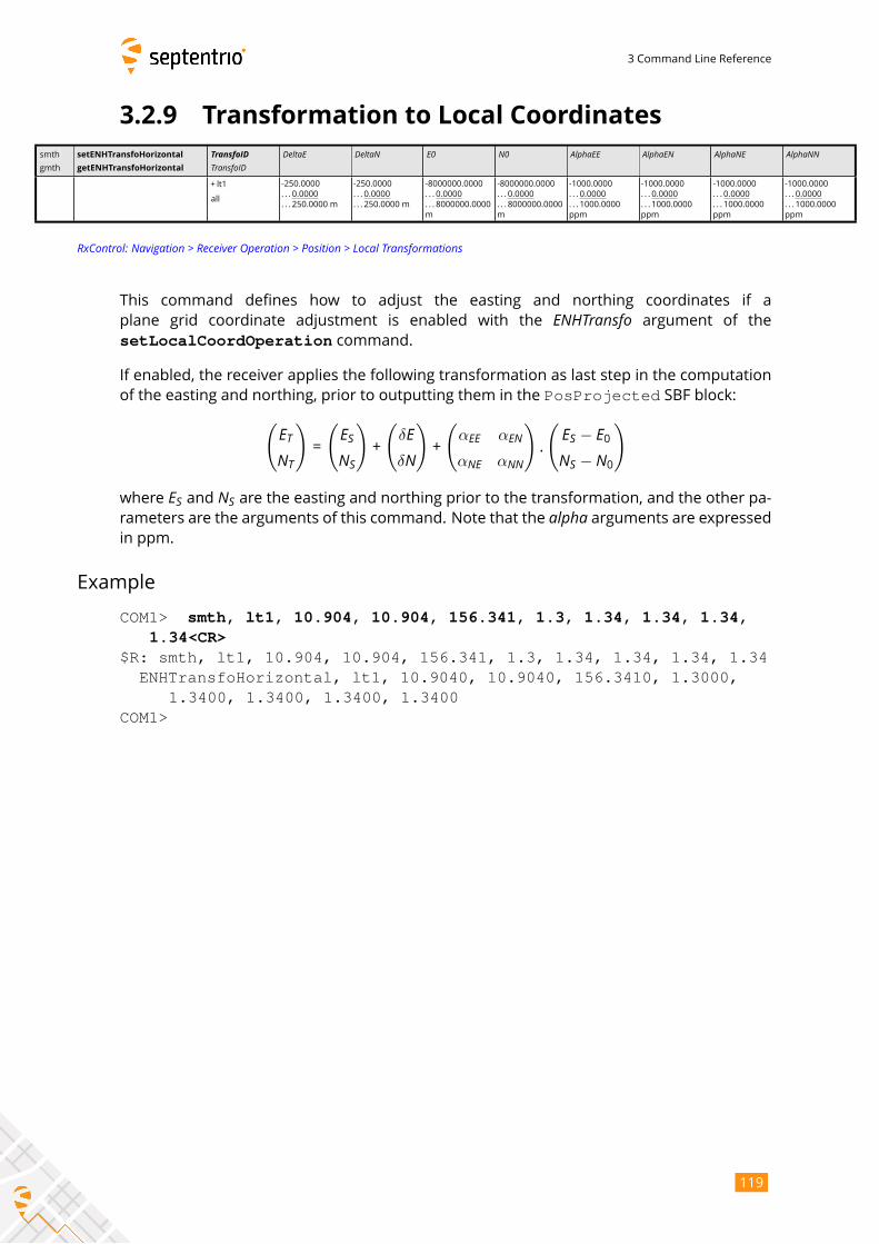
3 Command Line Reference
3.2.9 Transformation to Local Coordinates
smth
gmth
setENHTransfoHorizontal
getENHTransfoHorizontal
TransfoIDTransfoID
DeltaE DeltaN E0 N0 AlphaEE AlphaEN AlphaNE AlphaNN
+ lt1
all
-250.0000
. . . 0.0000
. . . 250.0000 m
-250.0000
. . . 0.0000
. . . 250.0000 m
-8000000.0000
. . . 0.0000
. . . 8000000.0000
m
-8000000.0000
. . . 0.0000
. . . 8000000.0000
m
-1000.0000
. . . 0.0000
. . . 1000.0000
ppm
-1000.0000
. . . 0.0000
. . . 1000.0000
ppm
-1000.0000
. . . 0.0000
. . . 1000.0000
ppm
-1000.0000
. . . 0.0000
. . . 1000.0000
ppm
RxControl: Navigation > Receiver Operation > Position > Local Transformations
This command defines how to adjust the easting and northing coordinates if a
plane grid coordinate adjustment is enabled with the ENHTransfo argument of thesetLocalCoordOperation command.
If enabled, the receiver applies the following transformation as last step in the computation
of the easting and northing, prior to outputting them in the PosProjected SBF block:(ETNT
)=
(ESNS
)+
(δEδN)+
(αEE αENαNE αNN
).
( ES − E0NS − N0
)
where ES and NS are the easting and northing prior to the transformation, and the other pa-rameters are the arguments of this command. Note that the alpha arguments are expressedin ppm.
Example
COM1> smth, lt1, 10.904, 10.904, 156.341, 1.3, 1.34, 1.34, 1.34,1.34<CR>
$R: smth, lt1, 10.904, 10.904, 156.341, 1.3, 1.34, 1.34, 1.34, 1.34ENHTransfoHorizontal, lt1, 10.9040, 10.9040, 156.3410, 1.3000,
1.3400, 1.3400, 1.3400, 1.3400COM1>
119
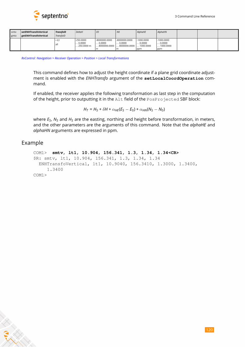
3 Command Line Reference
smtv
gmtv
setENHTransfoVertical
getENHTransfoVertical
TransfoIDTransfoID
DeltaH E0 N0 AlphaHE AlphaHN
+ lt1
all
-250.0000
. . . 0.0000
. . . 250.0000 m
-8000000.0000
. . . 0.0000
. . . 8000000.0000
m
-8000000.0000
. . . 0.0000
. . . 8000000.0000
m
-1000.0000
. . . 0.0000
. . . 1000.0000
ppm
-1000.0000
. . . 0.0000
. . . 1000.0000
ppm
RxControl: Navigation > Receiver Operation > Position > Local Transformations
This command defines how to adjust the height coordinate if a plane grid coordinate adjust-
ment is enabled with the ENHTransfo argument of the setLocalCoordOperation com-mand.
If enabled, the receiver applies the following transformation as last step in the computation
of the height, prior to outputting it in the Alt field of the PosProjected SBF block:
HT = HS + δH + αHE(ES − E0) + αHN(NS − N0)where ES, NS and HS are the easting, northing and height before transformation, in meters,and the other parameters are the arguments of this command. Note that the alphaHE andalphaHN arguments are expressed in ppm.
Example
COM1> smtv, lt1, 10.904, 156.341, 1.3, 1.34, 1.34<CR>$R: smtv, lt1, 10.904, 156.341, 1.3, 1.34, 1.34
ENHTransfoVertical, lt1, 10.9040, 156.3410, 1.3000, 1.3400,1.3400
COM1>
120
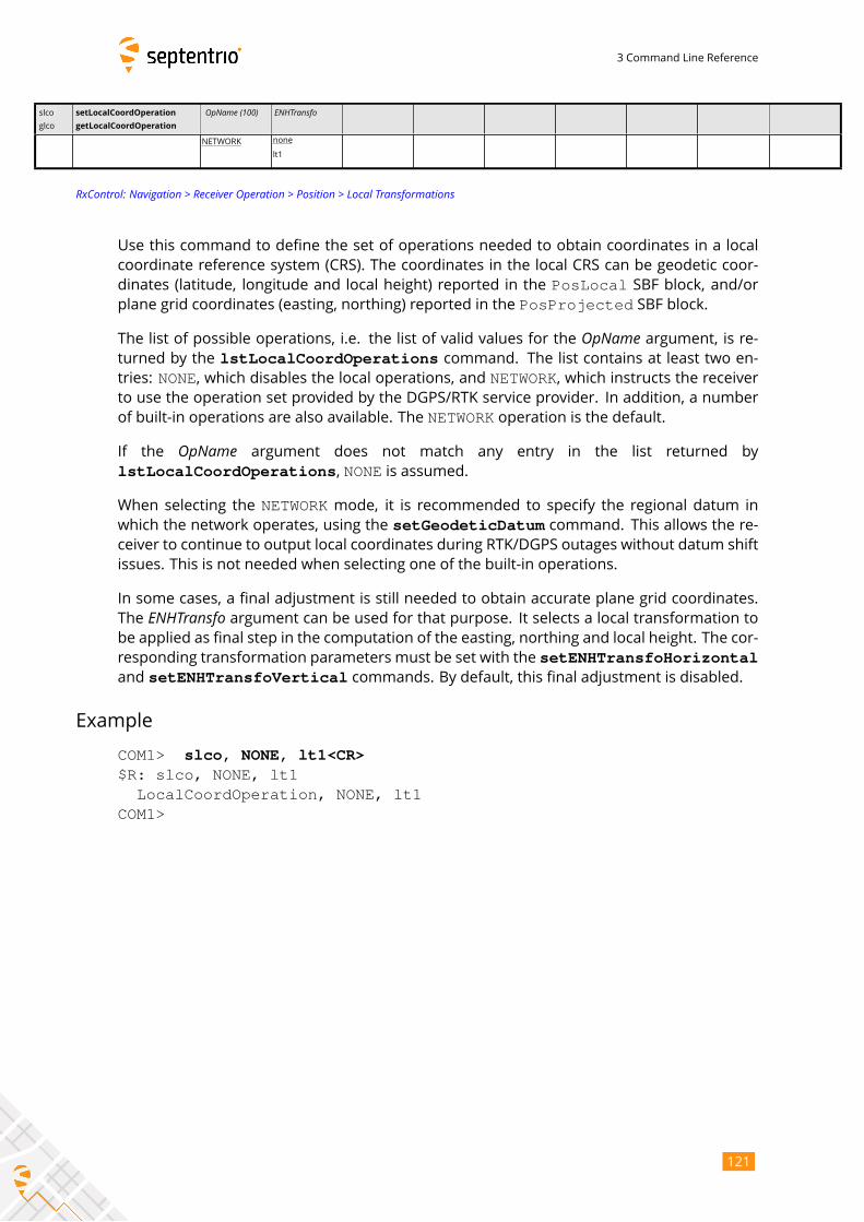
3 Command Line Reference
slco
glco
setLocalCoordOperation
getLocalCoordOperation
OpName (100) ENHTransfo
NETWORK none
lt1
RxControl: Navigation > Receiver Operation > Position > Local Transformations
Use this command to define the set of operations needed to obtain coordinates in a local
coordinate reference system (CRS). The coordinates in the local CRS can be geodetic coor-
dinates (latitude, longitude and local height) reported in the PosLocal SBF block, and/orplane grid coordinates (easting, northing) reported in the PosProjected SBF block.
The list of possible operations, i.e. the list of valid values for the OpName argument, is re-turned by the lstLocalCoordOperations command. The list contains at least two en-tries: NONE, which disables the local operations, and NETWORK, which instructs the receiverto use the operation set provided by the DGPS/RTK service provider. In addition, a number
of built-in operations are also available. The NETWORK operation is the default.
If the OpName argument does not match any entry in the list returned by
lstLocalCoordOperations, NONE is assumed.
When selecting the NETWORK mode, it is recommended to specify the regional datum inwhich the network operates, using the setGeodeticDatum command. This allows the re-ceiver to continue to output local coordinates during RTK/DGPS outages without datum shift
issues. This is not needed when selecting one of the built-in operations.
In some cases, a final adjustment is still needed to obtain accurate plane grid coordinates.
The ENHTransfo argument can be used for that purpose. It selects a local transformation tobe applied as final step in the computation of the easting, northing and local height. The cor-
responding transformation parameters must be set with the setENHTransfoHorizontaland setENHTransfoVertical commands. By default, this final adjustment is disabled.
Example
COM1> slco, NONE, lt1<CR>$R: slco, NONE, lt1
LocalCoordOperation, NONE, lt1COM1>
121
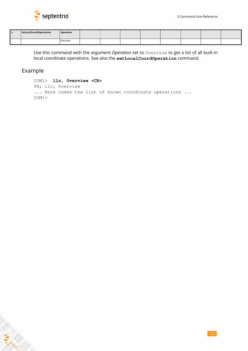
3 Command Line Reference
llc lstLocalCoordOperations Operation
Overview
Use this command with the argument Operation set to Overview to get a list of all built-inlocal coordinate operations. See also the setLocalCoordOperation command.
Example
COM1> llc, Overview <CR>$R; llc, Overview... Here comes the list of known coordinate operations ...COM1>
122
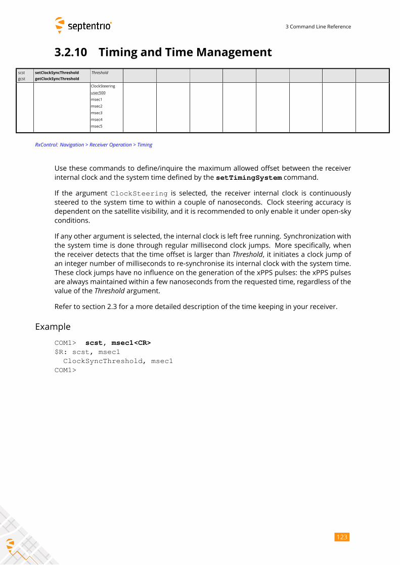
3 Command Line Reference
3.2.10 Timing and Time Management
scst
gcst
setClockSyncThreshold
getClockSyncThreshold
Threshold
ClockSteering
usec500
msec1
msec2
msec3
msec4
msec5
RxControl: Navigation > Receiver Operation > Timing
Use these commands to define/inquire the maximum allowed offset between the receiver
internal clock and the system time defined by the setTimingSystem command.
If the argument ClockSteering is selected, the receiver internal clock is continuouslysteered to the system time to within a couple of nanoseconds. Clock steering accuracy is
dependent on the satellite visibility, and it is recommended to only enable it under open-sky
conditions.
If any other argument is selected, the internal clock is left free running. Synchronization with
the system time is done through regular millisecond clock jumps. More specifically, when
the receiver detects that the time offset is larger than Threshold, it initiates a clock jump ofan integer number of milliseconds to re-synchronise its internal clock with the system time.
These clock jumps have no influence on the generation of the xPPS pulses: the xPPS pulses
are always maintained within a few nanoseconds from the requested time, regardless of the
value of the Threshold argument.Refer to section 2.3 for a more detailed description of the time keeping in your receiver.
Example
COM1> scst, msec1<CR>$R: scst, msec1
ClockSyncThreshold, msec1COM1>
123
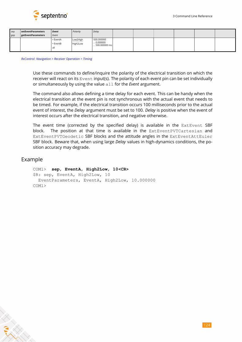
3 Command Line Reference
sep
gep
setEventParameters
getEventParameters
EventEvent
Polarity Delay
+ EventA
+ EventB
all
Low2High
High2Low
-500.000000
. . . 0.000000
. . . 500.000000 ms
RxControl: Navigation > Receiver Operation > Timing
Use these commands to define/inquire the polarity of the electrical transition on which the
receiver will react on its Event input(s). The polarity of each event pin can be set individuallyor simultaneously by using the value all for the Event argument.The command also allows defining a time delay for each event. This can be handy when the
electrical transition at the event pin is not synchronous with the actual event that needs to
be timed. For example, if the electrical transition occurs 100 milliseconds prior to the actual
event of interest, the Delay argument must be set to 100. Delay is positive when the event ofinterest occurs after the electrical transition, and negative otherwise.
The event time (corrected by the specified delay) is available in the ExtEvent SBFblock. The position at that time is available in the ExtEventPVTCartesian andExtEventPVTGeodetic SBF blocks and the attitude angles in the ExtEventAttEulerSBF block. Beware that, when using large Delay values in high-dynamics conditions, the po-sition accuracy may degrade.
Example
COM1> sep, EventA, High2Low, 10<CR>$R: sep, EventA, High2Low, 10
EventParameters, EventA, High2Low, 10.000000COM1>
124
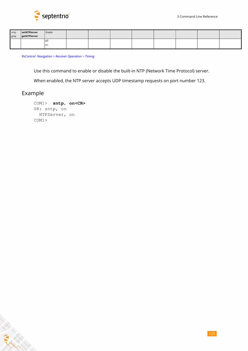
3 Command Line Reference
sntp
gntp
setNTPServer
getNTPServer
Enable
off
on
RxControl: Navigation > Receiver Operation > Timing
Use this command to enable or disable the built-in NTP (Network Time Protocol) server.
When enabled, the NTP server accepts UDP timestamp requests on port number 123.
Example
COM1> sntp, on<CR>$R: sntp, on
NTPServer, onCOM1>
125
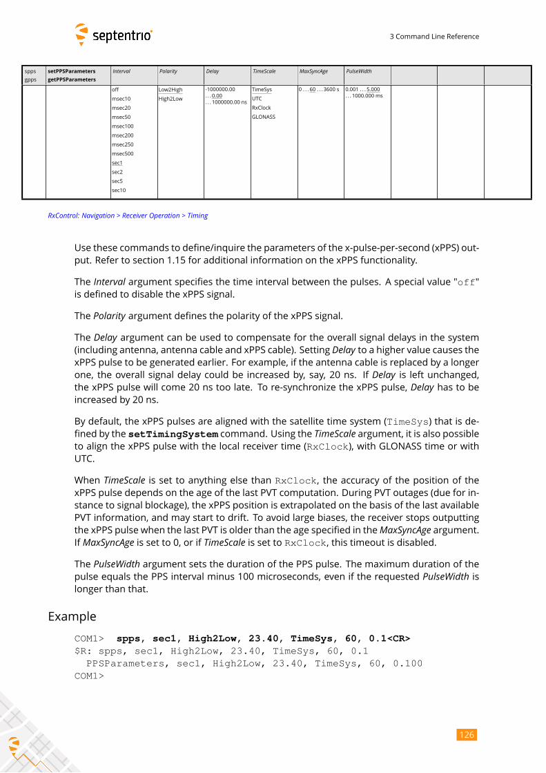
3 Command Line Reference
spps
gpps
setPPSParameters
getPPSParameters
Interval Polarity Delay TimeScale MaxSyncAge PulseWidth
off
msec10
msec20
msec50
msec100
msec200
msec250
msec500
sec1
sec2
sec5
sec10
Low2High
High2Low
-1000000.00
. . . 0.00
. . . 1000000.00 ns
TimeSys
UTC
RxClock
GLONASS
0 . . . 60 . . . 3600 s 0.001 . . . 5.000
. . . 1000.000 ms
RxControl: Navigation > Receiver Operation > Timing
Use these commands to define/inquire the parameters of the x-pulse-per-second (xPPS) out-
put. Refer to section 1.15 for additional information on the xPPS functionality.
The Interval argument specifies the time interval between the pulses. A special value "off"is defined to disable the xPPS signal.
The Polarity argument defines the polarity of the xPPS signal.The Delay argument can be used to compensate for the overall signal delays in the system(including antenna, antenna cable and xPPS cable). Setting Delay to a higher value causes thexPPS pulse to be generated earlier. For example, if the antenna cable is replaced by a longer
one, the overall signal delay could be increased by, say, 20 ns. If Delay is left unchanged,the xPPS pulse will come 20 ns too late. To re-synchronize the xPPS pulse, Delay has to beincreased by 20 ns.
By default, the xPPS pulses are aligned with the satellite time system (TimeSys) that is de-fined by the setTimingSystem command. Using the TimeScale argument, it is also possibleto align the xPPS pulse with the local receiver time (RxClock), with GLONASS time or withUTC.
When TimeScale is set to anything else than RxClock, the accuracy of the position of thexPPS pulse depends on the age of the last PVT computation. During PVT outages (due for in-
stance to signal blockage), the xPPS position is extrapolated on the basis of the last available
PVT information, and may start to drift. To avoid large biases, the receiver stops outputting
the xPPS pulse when the last PVT is older than the age specified in theMaxSyncAge argument.If MaxSyncAge is set to 0, or if TimeScale is set to RxClock, this timeout is disabled.The PulseWidth argument sets the duration of the PPS pulse. The maximum duration of thepulse equals the PPS interval minus 100 microseconds, even if the requested PulseWidth islonger than that.
Example
COM1> spps, sec1, High2Low, 23.40, TimeSys, 60, 0.1<CR>$R: spps, sec1, High2Low, 23.40, TimeSys, 60, 0.1
PPSParameters, sec1, High2Low, 23.40, TimeSys, 60, 0.100COM1>
126
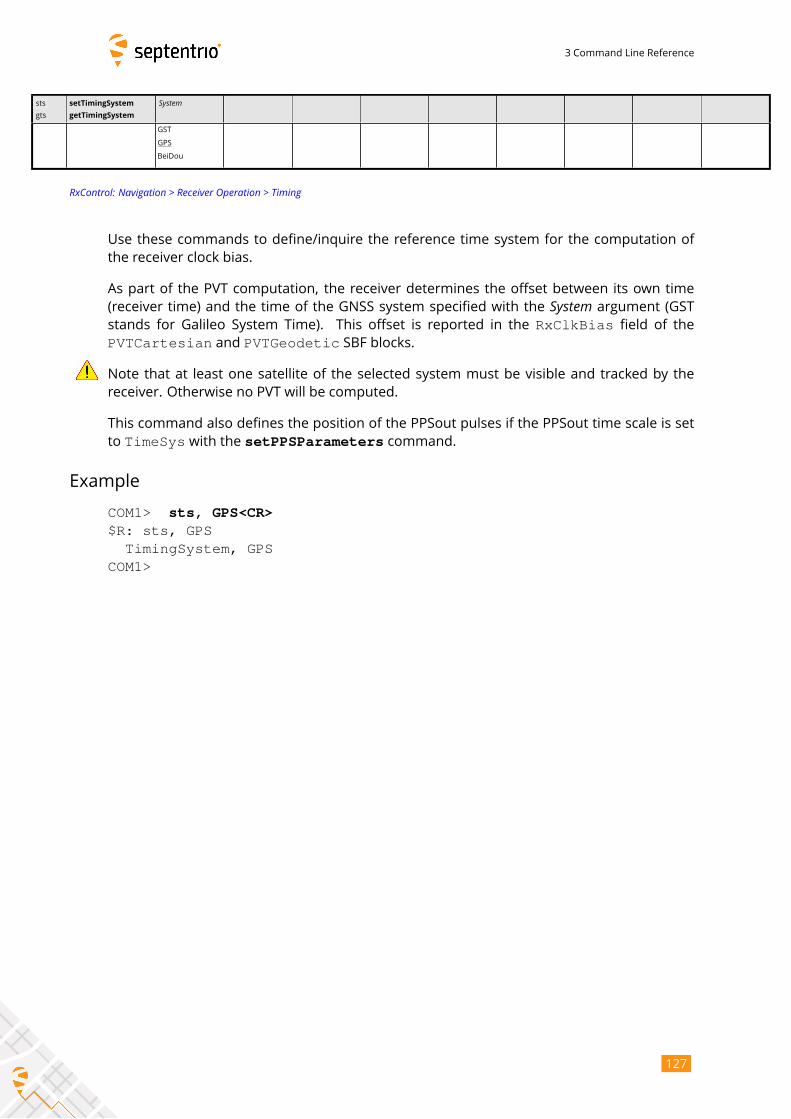
3 Command Line Reference
sts
gts
setTimingSystem
getTimingSystem
System
GST
GPS
BeiDou
RxControl: Navigation > Receiver Operation > Timing
Use these commands to define/inquire the reference time system for the computation of
the receiver clock bias.
As part of the PVT computation, the receiver determines the offset between its own time
(receiver time) and the time of the GNSS system specified with the System argument (GSTstands for Galileo System Time). This offset is reported in the RxClkBias field of the
PVTCartesian and PVTGeodetic SBF blocks.
Note that at least one satellite of the selected system must be visible and tracked by the
receiver. Otherwise no PVT will be computed.
This command also defines the position of the PPSout pulses if the PPSout time scale is set
to TimeSys with the setPPSParameters command.
Example
COM1> sts, GPS<CR>$R: sts, GPS
TimingSystem, GPSCOM1>
127
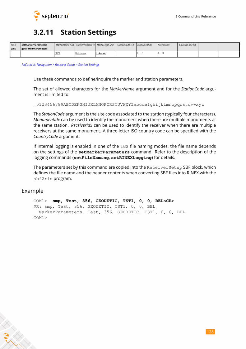
3 Command Line Reference
3.2.11 Station Settings
smp
gmp
setMarkerParameters
getMarkerParameters
MarkerName (60) MarkerNumber (20)MarkerType (20) StationCode (10) MonumentIdx ReceiverIdx CountryCode (3)
SEPT Unknown Unknown 0 . . . 9 0 . . . 9
RxControl: Navigation > Receiver Setup > Station Settings
Use these commands to define/inquire the marker and station parameters.
The set of allowed characters for the MarkerName argument and for the StationCode argu-ment is limited to:
_0123456789ABCDEFGHIJKLMNOPQRSTUVWXYZabcdefghijklmnopqrstuvwxyz
The StationCode argument is the site code associated to the station (typically four characters).MonumentIdx can be used to identify the monument when there are multiple monuments atthe same station. ReceiverIdx can be used to identify the receiver when there are multiplereceivers at the same monument. A three-letter ISO country code can be specified with theCountryCode argument.If internal logging is enabled in one of the IGS file naming modes, the file name depends
on the settings of the setMarkerParameters command. Refer to the description of thelogging commands (setFileNaming, setRINEXLogging) for details.
The parameters set by this command are copied into the ReceiverSetup SBF block, whichdefines the file name and the header contents when converting SBF files into RINEX with the
sbf2rin program.
Example
COM1> smp, Test, 356, GEODETIC, TST1, 0, 0, BEL<CR>$R: smp, Test, 356, GEODETIC, TST1, 0, 0, BEL
MarkerParameters, Test, 356, GEODETIC, TST1, 0, 0, BELCOM1>
128
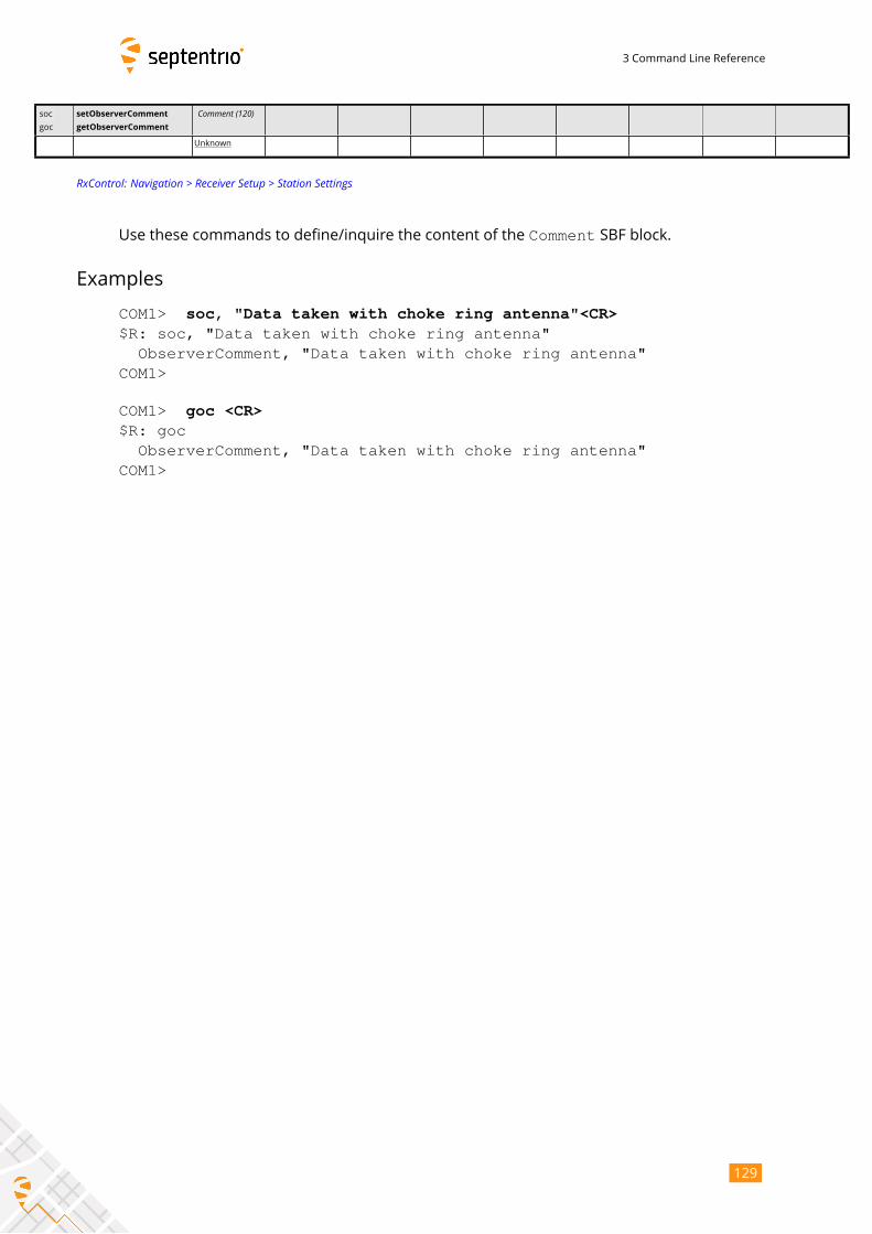
3 Command Line Reference
soc
goc
setObserverComment
getObserverComment
Comment (120)
Unknown
RxControl: Navigation > Receiver Setup > Station Settings
Use these commands to define/inquire the content of the Comment SBF block.
Examples
COM1> soc, "Data taken with choke ring antenna"<CR>$R: soc, "Data taken with choke ring antenna"
ObserverComment, "Data taken with choke ring antenna"COM1>
COM1> goc <CR>$R: goc
ObserverComment, "Data taken with choke ring antenna"COM1>
129
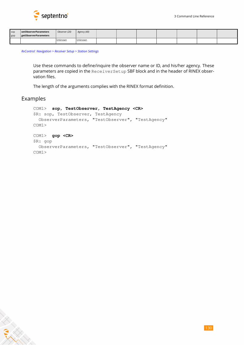
3 Command Line Reference
sop
gop
setObserverParameters
getObserverParameters
Observer (20) Agency (40)
Unknown Unknown
RxControl: Navigation > Receiver Setup > Station Settings
Use these commands to define/inquire the observer name or ID, and his/her agency. These
parameters are copied in the ReceiverSetup SBF block and in the header of RINEX obser-vation files.
The length of the arguments complies with the RINEX format definition.
Examples
COM1> sop, TestObserver, TestAgency <CR>$R: sop, TestObserver, TestAgency
ObserverParameters, "TestObserver", "TestAgency"COM1>
COM1> gop <CR>$R: gop
ObserverParameters, "TestObserver", "TestAgency"COM1>
130
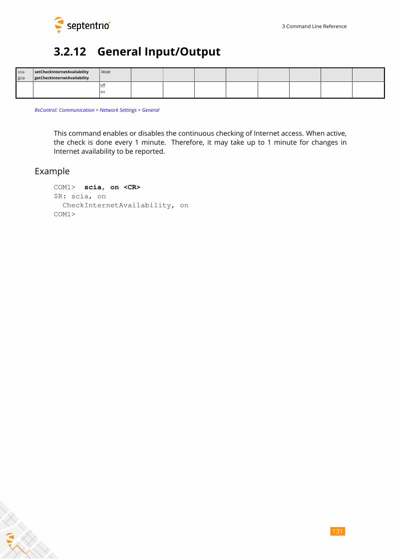
3 Command Line Reference
3.2.12 General Input/Output
scia
gcia
setCheckInternetAvailability
getCheckInternetAvailability
Mode
off
on
RxControl: Communication > Network Settings > General
This command enables or disables the continuous checking of Internet access. When active,
the check is done every 1 minute. Therefore, it may take up to 1 minute for changes in
Internet availability to be reported.
Example
COM1> scia, on <CR>$R: scia, on
CheckInternetAvailability, onCOM1>
131
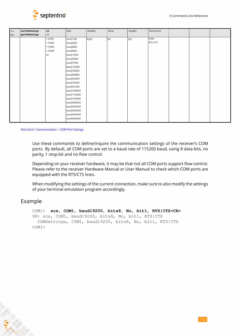
3 Command Line Reference
scs
gcs
setCOMSettings
getCOMSettings
CdCd
Rate DataBits Parity StopBits FlowControl
+COM1
+COM2
+COM3
+COM4
all
baud1200
baud2400
baud4800
baud9600
baud19200
baud38400
baud57600
baud115200
baud230400
baud460800
baud500000
baud576000
baud921600
baud1000000
baud1152000
baud1500000
baud2000000
baud2500000
baud3000000
baud3500000
baud4000000
bits8 No bit1 none
RTS|CTS
RxControl: Communication > COM Port Settings
Use these commands to define/inquire the communication settings of the receiver’s COM
ports. By default, all COM ports are set to a baud rate of 115200 baud, using 8 data-bits, no
parity, 1 stop-bit and no flow control.
Depending on your receiver hardware, it may be that not all COM ports support flow control.
Please refer to the receiver Hardware Manual or User Manual to check which COM ports are
equipped with the RTS/CTS lines.
Whenmodifying the settings of the current connection, make sure to alsomodify the settings
of your terminal emulation program accordingly.
Example
COM1> scs, COM1, baud19200, bits8, No, bit1, RTS|CTS<CR>$R: scs, COM1, baud19200, bits8, No, bit1, RTS|CTS
COMSettings, COM1, baud19200, bits8, No, bit1, RTS|CTSCOM1>
132
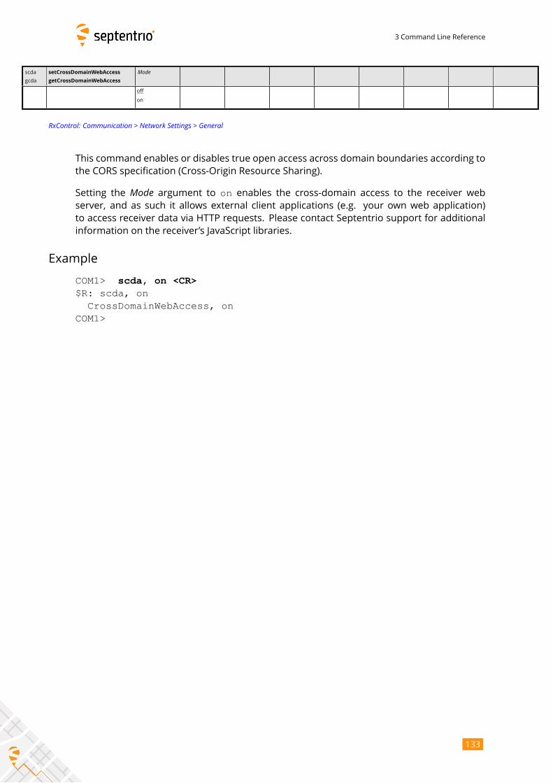
3 Command Line Reference
scda
gcda
setCrossDomainWebAccess
getCrossDomainWebAccess
Mode
off
on
RxControl: Communication > Network Settings > General
This command enables or disables true open access across domain boundaries according to
the CORS specification (Cross-Origin Resource Sharing).
Setting the Mode argument to on enables the cross-domain access to the receiver webserver, and as such it allows external client applications (e.g. your own web application)
to access receiver data via HTTP requests. Please contact Septentrio support for additional
information on the receiver’s JavaScript libraries.
Example
COM1> scda, on <CR>$R: scda, on
CrossDomainWebAccess, onCOM1>
133
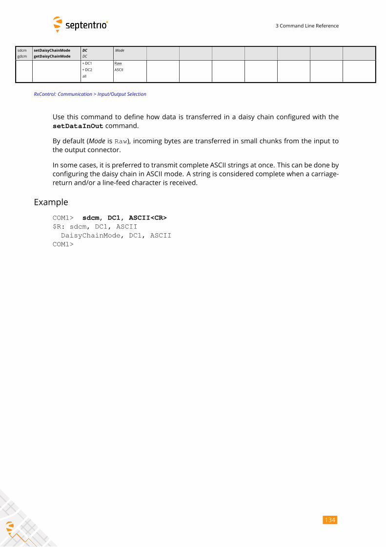
3 Command Line Reference
sdcm
gdcm
setDaisyChainMode
getDaisyChainMode
DCDC
Mode
+DC1
+DC2
all
Raw
ASCII
RxControl: Communication > Input/Output Selection
Use this command to define how data is transferred in a daisy chain configured with the
setDataInOut command.
By default (Mode is Raw), incoming bytes are transferred in small chunks from the input tothe output connector.
In some cases, it is preferred to transmit complete ASCII strings at once. This can be done by
configuring the daisy chain in ASCIImode. A string is considered complete when a carriage-
return and/or a line-feed character is received.
Example
COM1> sdcm, DC1, ASCII<CR>$R: sdcm, DC1, ASCII
DaisyChainMode, DC1, ASCIICOM1>
134
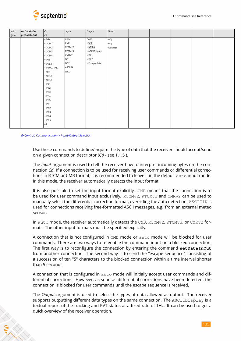
3 Command Line Reference
sdio
gdio
setDataInOut
getDataInOut
CdCd
Input Output Show
+DSK1
+COM1
+COM2
+COM3
+COM4
+USB1
+USB2
+ IP10 ... IP17
+NTR1
+NTR2
+NTR3
+ IPS1
+ IPS2
+ IPS3
+ IPS4
+ IPS5
+ IPR1
+ IPR2
+ IPR3
+ IPR4
+ IPR5
all
none
CMD
RTCMv2
RTCMv3
CMRv2
DC1
DC2
ASCIIIN
auto
none
+ SBF
+NMEA
+ASCIIDisplay
+DC1
+DC2
+ Encapsulate
(off)
(on)
(waiting)
RxControl: Communication > Input/Output Selection
Use these commands to define/inquire the type of data that the receiver should accept/send
on a given connection descriptor (Cd - see 1.1.5 ).The Input argument is used to tell the receiver how to interpret incoming bytes on the con-nection Cd. If a connection is to be used for receiving user commands or differential correc-tions in RTCM or CMR format, it is recommended to leave it in the default auto input mode.In this mode, the receiver automatically detects the input format.
It is also possible to set the input format explicitly. CMD means that the connection is tobe used for user command input exclusively. RTCMv2, RTCMv3 and CMRv2 can be used tomanually select the differential correction format, overriding the auto detection. ASCIIIN isused for connections receiving free-formatted ASCII messages, e.g. from an external meteo
sensor.
In auto mode, the receiver automatically detects the CMD, RTCMv2, RTCMv3, or CMRv2 for-mats. The other input formats must be specified explicitly.
A connection that is not configured in CMD mode or auto mode will be blocked for usercommands. There are two ways to re-enable the command input on a blocked connection.
The first way is to reconfigure the connection by entering the command setDataInOutfrom another connection. The second way is to send the "escape sequence" consisting of
a succession of ten "S" characters to the blocked connection within a time interval shorter
than 5 seconds.
A connection that is configured in auto mode will initially accept user commands and dif-ferential corrections. However, as soon as differential corrections have been detected, the
connection is blocked for user commands until the escape sequence is received.
The Output argument is used to select the types of data allowed as output. The receiversupports outputting different data types on the same connection. The ASCIIDisplay is atextual report of the tracking and PVT status at a fixed rate of 1Hz. It can be used to get a
quick overview of the receiver operation.
135
3 Command Line Reference
The Encapsulate option has the effect of encapsulating all non-SBF output into
the EncapsulatedOutput SBF block. For instance, setting the Output argument toNMEA+Encapsulate instructs the receiver to encapsulate all NMEA messages into theEncapsulatedOutput SBF block.
DC1 and DC2 represent two internal pipes that can be used to create a daisy-chain. Set theInput argument to DCi to connect the input of pipe i to the specified connection. Set the Out-put argument to DCi to connect the output of pipe i to the specified connection. The daisy-chain can operate in binary or ASCII mode, as configured with the setDaisyChainModecommand.
After the Cd, Input and Output arguments, an extra read-only Show argument will be returnedin the command reply. This last argument can take the value on, off or waiting, dependingon whether the connection descriptor is open, close, or waiting for a connection.
The Input argument is ignored for output-only connections, and the Output argument is ig-nored for input-only connections. See section 1.1.5 for details.
Note that not all input connections can accept user commands, check section 1.1.5 for de-
tails.
Examples
COM1> sdio, COM1, CMD <CR>$R: sdio, COM1, CMD
DataInOut, COM1, CMD, SBF, (on)COM1>
On receivers that have three COM ports, to set up a two-way daisy-chain between COM2 and
COM3, i.e. to have all incoming bytes from COM2 redirected to COM3 and all incoming bytes
from COM3 redirected to COM2, enter the following commands from a connection different
than COM2 and COM3:
COM1> sdio, COM2, DC1, DC2 <CR>$R: sdio, COM2, DC1, DC2
DataInOut, COM2, DC1, DC2, (on)COM1> sdio, COM3, DC2, DC1 <CR>$R: sdio, COM3, DC2, DC1
DataInOut, COM3, DC2, DC1, (on)COM1>
136
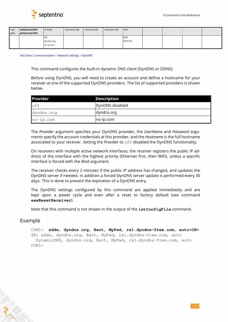
3 Command Line Reference
sdds
gdds
setDynamicDNS
getDynamicDNS
Provider UserName (40) Password (40) Hostname (40) Bind
off
dyndns.org
no-ip.com
auto
Ethernet
RxControl: Communication > Network Settings > DynDNS
This command configures the built-in dynamic DNS client (DynDNS or DDNS).
Before using DynDNS, you will need to create an account and define a hostname for your
receiver at one of the supported DynDNS providers. The list of supported providers is shown
below.
Provider Description
off DynDNS disabled
dyndns.org dyndns.org
no-ip.com no-ip.com
The Provider argument specifies your DynDNS provider, the UserName and Password argu-ments specify the account credentials at this provider, and the Hostname is the full hostnameassociated to your receiver. Setting the Provider to off disabled the DynDNS functionality.On receivers with multiple active network interfaces, the receiver registers the public IP ad-
dress of the interface with the highest priority (Ethernet first, then WiFi), unless a specific
interface is forced with the Bind argument.The receiver checks every 2 minutes if the public IP address has changed, and updates the
DynDNS server if needed. In addition a forced DynDNS server update is performed every 30
days. This is done to prevent the expiration of a DynDNS entry.
The DynDNS settings configured by this command are applied immediately and are
kept upon a power cycle and even after a reset to factory default (see command
exeResetReceiver).
Note that this command is not shown in the output of the lstConfigFile command.
Example
COM1> sdds, dyndns.org, Bart, MyPwd, rx1.dyndns-free.com, auto<CR>$R: sdds, dyndns.org, Bart, MyPwd, rx1.dyndns-free.com, auto
DynamicDNS, dyndns.org, Bart, MyPwd, rx1.dyndns-free.com, autoCOM1>
137

3 Command Line Reference
eecm
gecm
exeEchoMessage
getEchoMessage
Cd Message (242) EndOfLine
DSK1
COM1
COM2
COM3
COM4
USB1
USB2
IP10 ... IP17
IPS1
IPS2
IPS3
IPS4
IPS5
IPR1
IPR2
IPR3
IPR4
IPR5
DC1
DC2
A:Unknown none
+CR
+ LF
all
RxControl: Communication > Output Settings > Echo Message
Use this command to send a message to one of the connections of the receiver.
The Message argument defines the message that should be sent on the Cd port. If the givenmessage starts with "A:", the remainder of the message is considered an ASCII string thatwill be forwarded without changes to the requested connection. If the given message starts
with "H:", the remainder of the message is considered a hexadecimal representation of asuccession of bytes to be sent to the requested connection. In this case, the string should be
a succession of 2-character hexadecimal values separated by a single whitespace.
Make sure to enclose the string between double quotes if it contains whitespaces. The max-
imum length of the Message argument (including the A: or H: prefix) is 242 characters.The EndOfLine argument defines which end-of-line character should be sent after the mes-sage. That argument is ignored when the Message argument starts with H:.To send a message at a regular interval instead of once, use the command
setPeriodicEcho.
When the Cd argument is DC1 or DC2, the message is injected into one of the internal daisy-chain pipes. See the setDataInOut command for details.
Examples
To send the string "Hello world!" to COM2, use:
COM1> eecm, COM2, "A:Hello world!", none <CR>$R: eecm, COM2, "A:Hello world!", none
EchoMessage, COM2, "A:Hello world!", noneCOM1>
To send the same string, the following command can also be used:
COM1> eecm, COM2, "H:48 65 6C 6C 6F 20 77 6F 72 6C 64 21", none<CR>
138

3 Command Line Reference
$R: eecm, COM2, "H:48 65 6C 6C 6F 20 77 6F 72 6C 64 21", noneEchoMessage, COM2, "H:48 65 6C 6C 6F 20 77 6F 72 6C 64 21", none
COM1>
139
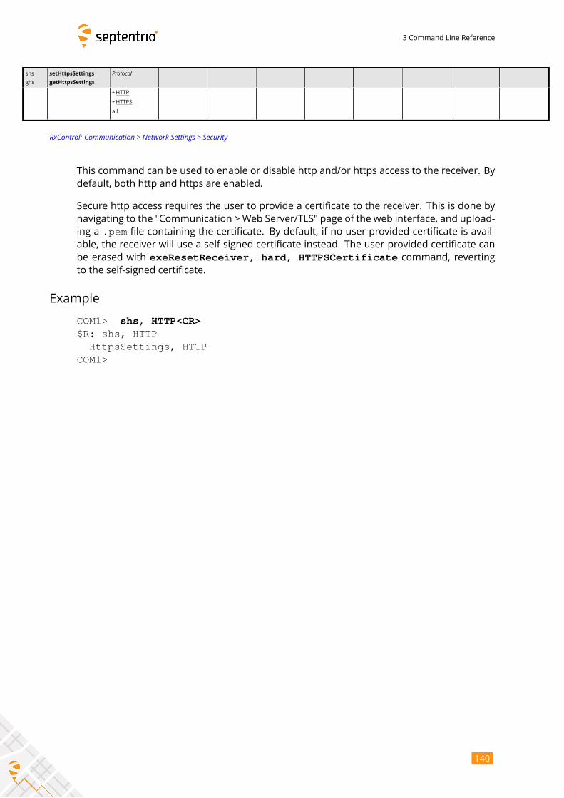
3 Command Line Reference
shs
ghs
setHttpsSettings
getHttpsSettings
Protocol
+HTTP
+HTTPS
all
RxControl: Communication > Network Settings > Security
This command can be used to enable or disable http and/or https access to the receiver. By
default, both http and https are enabled.
Secure http access requires the user to provide a certificate to the receiver. This is done by
navigating to the "Communication > Web Server/TLS" page of the web interface, and upload-
ing a .pem file containing the certificate. By default, if no user-provided certificate is avail-
able, the receiver will use a self-signed certificate instead. The user-provided certificate can
be erased with exeResetReceiver, hard, HTTPSCertificate command, revertingto the self-signed certificate.
Example
COM1> shs, HTTP<CR>$R: shs, HTTP
HttpsSettings, HTTPCOM1>
140
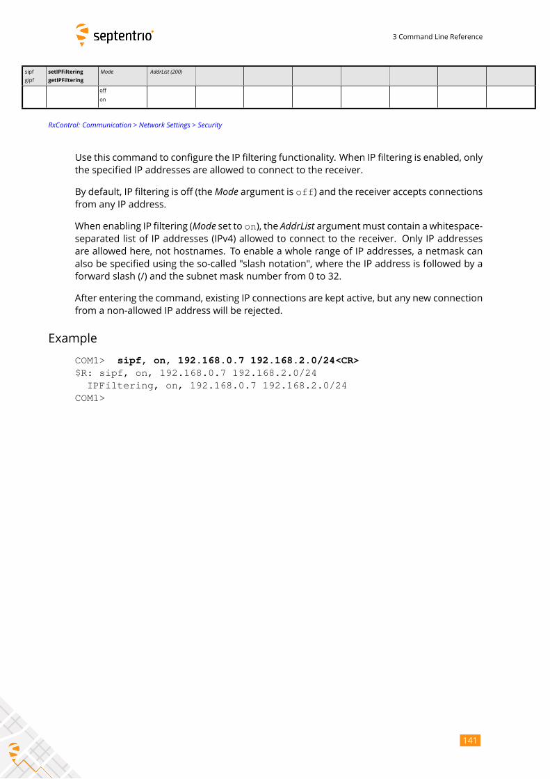
3 Command Line Reference
sipf
gipf
setIPFiltering
getIPFiltering
Mode AddrList (200)
off
on
RxControl: Communication > Network Settings > Security
Use this command to configure the IP filtering functionality. When IP filtering is enabled, only
the specified IP addresses are allowed to connect to the receiver.
By default, IP filtering is off (theMode argument is off) and the receiver accepts connectionsfrom any IP address.
When enabling IP filtering (Mode set to on), the AddrList argumentmust contain a whitespace-separated list of IP addresses (IPv4) allowed to connect to the receiver. Only IP addresses
are allowed here, not hostnames. To enable a whole range of IP addresses, a netmask can
also be specified using the so-called "slash notation", where the IP address is followed by a
forward slash (/) and the subnet mask number from 0 to 32.
After entering the command, existing IP connections are kept active, but any new connection
from a non-allowed IP address will be rejected.
Example
COM1> sipf, on, 192.168.0.7 192.168.2.0/24<CR>$R: sipf, on, 192.168.0.7 192.168.2.0/24
IPFiltering, on, 192.168.0.7 192.168.2.0/24COM1>
141
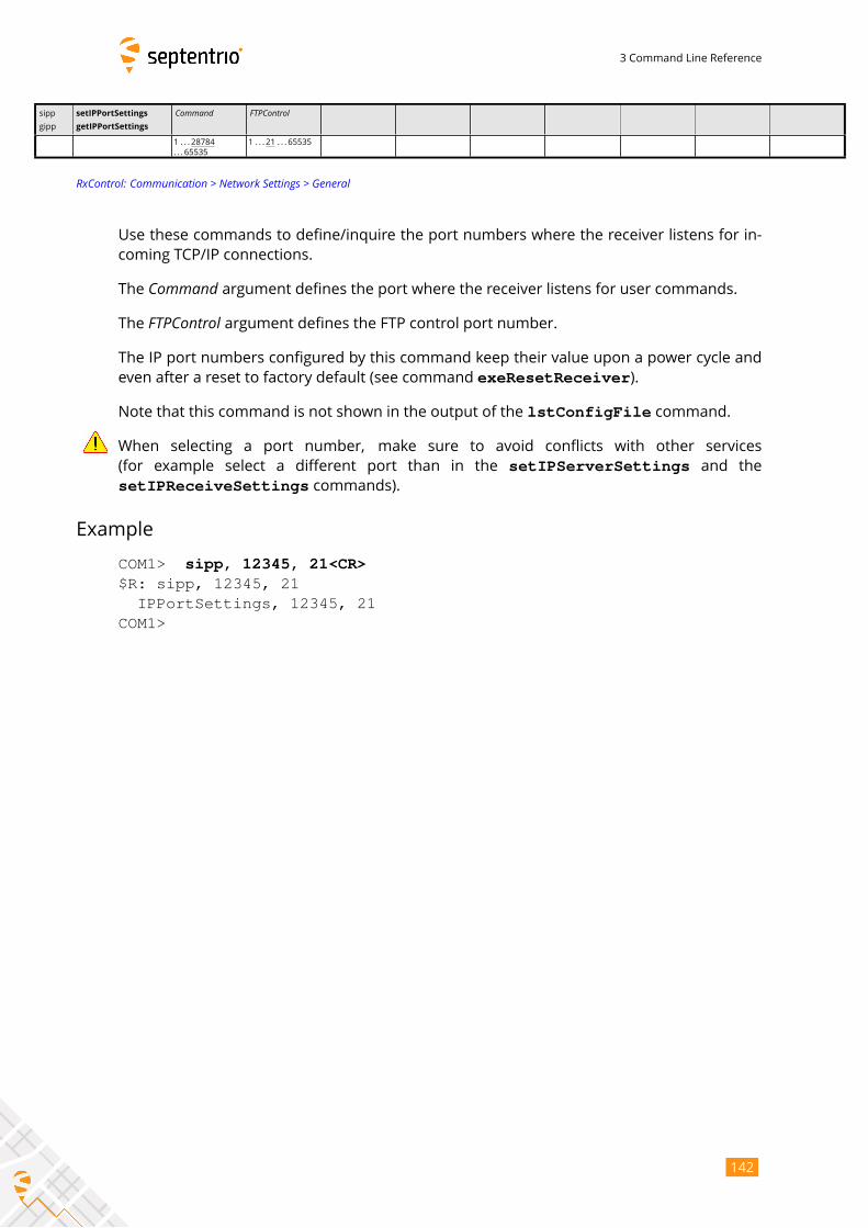
3 Command Line Reference
sipp
gipp
setIPPortSettings
getIPPortSettings
Command FTPControl
1 . . . 28784
. . . 65535
1 . . . 21 . . . 65535
RxControl: Communication > Network Settings > General
Use these commands to define/inquire the port numbers where the receiver listens for in-
coming TCP/IP connections.
The Command argument defines the port where the receiver listens for user commands.The FTPControl argument defines the FTP control port number.The IP port numbers configured by this command keep their value upon a power cycle and
even after a reset to factory default (see command exeResetReceiver).
Note that this command is not shown in the output of the lstConfigFile command.
When selecting a port number, make sure to avoid conflicts with other services
(for example select a different port than in the setIPServerSettings and the
setIPReceiveSettings commands).
Example
COM1> sipp, 12345, 21<CR>$R: sipp, 12345, 21
IPPortSettings, 12345, 21COM1>
142
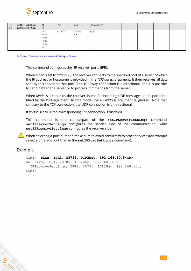
3 Command Line Reference
sirs
girs
setIPReceiveSettings
getIPReceiveSettings
CdCd
Port Mode TCPAddress (40)
+ IPR1
+ IPR2
+ IPR3
+ IPR4
+ IPR5
all
0 . . . 65535 TCP2Way
UDP
0.0.0.0
RxControl: Communication > Network Settings > General
This command configures the "IP receive" ports (IPR).
WhenMode is set to TCP2Way, the receiver connects to the specified port of a server of whichthe IP address or hostname is provided in the TCPAddress argument. It then receives all datasent by this server on that port. The TCP2Way connection is bidirectional, and it is possible
to send data to the server or to process commands from the server.
When Mode is set to UDP, the receiver listens for incoming UDP messages on its port iden-tified by the Port argument. In UDP mode, the TCPAddress argument is ignored. Note that,contrary to the TCP connection, the UDP connection is unidirectional.
If Port is set to 0, the corresponding IPR connection is disabled.This command is the counterpart of the setIPServerSettings command.
setIPServerSettings configures the sender side of the communication, while
setIPReceiveSettings configures the receiver side.
When selecting a port number, make sure to avoid conflicts with other services (for example
select a different port than in the setIPPortSettings command).
Example
COM1> sirs, IPR1, 28785, TCP2Way, 192.168.10.5<CR>$R: sirs, IPR1, 28785, TCP2Way, 192.168.10.5
IPReceiveSettings, IPR1, 28785, TCP2Way, 192.168.10.5COM1>
143
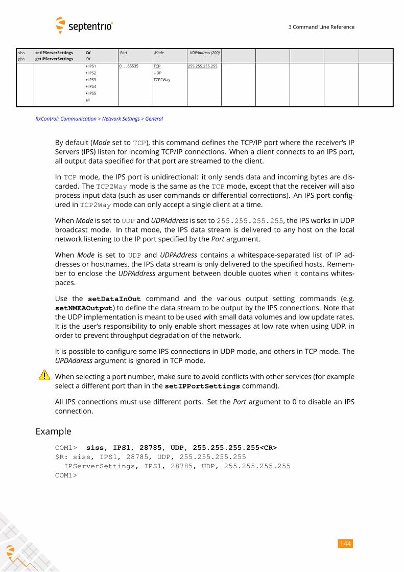
3 Command Line Reference
siss
giss
setIPServerSettings
getIPServerSettings
CdCd
Port Mode UDPAddress (200)
+ IPS1
+ IPS2
+ IPS3
+ IPS4
+ IPS5
all
0 . . . 65535 TCP
UDP
TCP2Way
255.255.255.255
RxControl: Communication > Network Settings > General
By default (Mode set to TCP), this command defines the TCP/IP port where the receiver’s IPServers (IPS) listen for incoming TCP/IP connections. When a client connects to an IPS port,
all output data specified for that port are streamed to the client.
In TCP mode, the IPS port is unidirectional: it only sends data and incoming bytes are dis-carded. The TCP2Waymode is the same as the TCPmode, except that the receiver will alsoprocess input data (such as user commands or differential corrections). An IPS port config-
ured in TCP2Waymode can only accept a single client at a time.
WhenMode is set to UDP and UDPAddress is set to 255.255.255.255, the IPS works in UDPbroadcast mode. In that mode, the IPS data stream is delivered to any host on the local
network listening to the IP port specified by the Port argument.When Mode is set to UDP and UDPAddress contains a whitespace-separated list of IP ad-dresses or hostnames, the IPS data stream is only delivered to the specified hosts. Remem-
ber to enclose the UDPAddress argument between double quotes when it contains whites-paces.
Use the setDataInOut command and the various output setting commands (e.g.
setNMEAOutput) to define the data stream to be output by the IPS connections. Note thatthe UDP implementation is meant to be used with small data volumes and low update rates.
It is the user’s responsibility to only enable short messages at low rate when using UDP, in
order to prevent throughput degradation of the network.
It is possible to configure some IPS connections in UDP mode, and others in TCP mode. TheUPDAddress argument is ignored in TCP mode.When selecting a port number, make sure to avoid conflicts with other services (for example
select a different port than in the setIPPortSettings command).
All IPS connections must use different ports. Set the Port argument to 0 to disable an IPSconnection.
Example
COM1> siss, IPS1, 28785, UDP, 255.255.255.255<CR>$R: siss, IPS1, 28785, UDP, 255.255.255.255
IPServerSettings, IPS1, 28785, UDP, 255.255.255.255COM1>
144
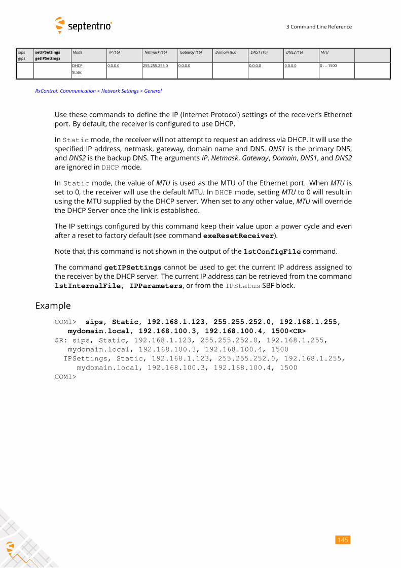
3 Command Line Reference
sips
gips
setIPSettings
getIPSettings
Mode IP (16) Netmask (16) Gateway (16) Domain (63) DNS1 (16) DNS2 (16) MTU
DHCP
Static
0.0.0.0 255.255.255.0 0.0.0.0 0.0.0.0 0.0.0.0 0 . . . 1500
RxControl: Communication > Network Settings > General
Use these commands to define the IP (Internet Protocol) settings of the receiver’s Ethernet
port. By default, the receiver is configured to use DHCP.
In Staticmode, the receiver will not attempt to request an address via DHCP. It will use thespecified IP address, netmask, gateway, domain name and DNS. DNS1 is the primary DNS,and DNS2 is the backup DNS. The arguments IP, Netmask, Gateway, Domain, DNS1, and DNS2are ignored in DHCPmode.
In Static mode, the value of MTU is used as the MTU of the Ethernet port. When MTU isset to 0, the receiver will use the default MTU. In DHCP mode, setting MTU to 0 will result inusing the MTU supplied by the DHCP server. When set to any other value, MTU will overridethe DHCP Server once the link is established.
The IP settings configured by this command keep their value upon a power cycle and even
after a reset to factory default (see command exeResetReceiver).
Note that this command is not shown in the output of the lstConfigFile command.
The command getIPSettings cannot be used to get the current IP address assigned tothe receiver by the DHCP server. The current IP address can be retrieved from the command
lstInternalFile, IPParameters, or from the IPStatus SBF block.
Example
COM1> sips, Static, 192.168.1.123, 255.255.252.0, 192.168.1.255,mydomain.local, 192.168.100.3, 192.168.100.4, 1500<CR>
$R: sips, Static, 192.168.1.123, 255.255.252.0, 192.168.1.255,mydomain.local, 192.168.100.3, 192.168.100.4, 1500
IPSettings, Static, 192.168.1.123, 255.255.252.0, 192.168.1.255,mydomain.local, 192.168.100.3, 192.168.100.4, 1500
COM1>
145
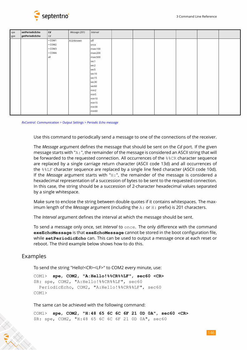
3 Command Line Reference
spe
gpe
setPeriodicEcho
getPeriodicEcho
CdCd
Message (201) Interval
+COM1
+COM2
+COM3
+COM4
all
A:Unknown off
once
msec100
msec200
msec500
sec1
sec2
sec5
sec10
sec15
sec30
sec60
min2
min5
min10
min15
min30
min60
RxControl: Communication > Output Settings > Periodic Echo message
Use this command to periodically send a message to one of the connections of the receiver.
The Message argument defines the message that should be sent on the Cd port. If the givenmessage starts with "A:", the remainder of themessage is considered an ASCII string that willbe forwarded to the requested connection. All occurrences of the %%CR character sequenceare replaced by a single carriage return character (ASCII code 13d) and all occurrences of
the %%LF character sequence are replaced by a single line feed character (ASCII code 10d).If the Message argument starts with "H:", the remainder of the message is considered ahexadecimal representation of a succession of bytes to be sent to the requested connection.
In this case, the string should be a succession of 2-character hexadecimal values separated
by a single whitespace.
Make sure to enclose the string between double quotes if it contains whitespaces. The max-
imum length of the Message argument (including the A: or H: prefix) is 201 characters.The Interval argument defines the interval at which the message should be sent.To send a message only once, set Interval to once. The only difference with the commandexeEchoMessage is that exeEchoMessage cannot be stored in the boot configuration file,while setPeriodicEcho can. This can be used to output a message once at each reset orreboot. The third example below shows how to do this.
Examples
To send the string "Hello!<CR><LF>" to COM2 every minute, use:
COM1> spe, COM2, "A:Hello!%%CR%%LF", sec60 <CR>$R: spe, COM2, "A:Hello!%%CR%%LF", sec60
PeriodicEcho, COM2, "A:Hello!%%CR%%LF", sec60COM1>
The same can be achieved with the following command:
COM1> spe, COM2, "H:48 65 6C 6C 6F 21 0D 0A", sec60 <CR>$R: spe, COM2, "H:48 65 6C 6C 6F 21 0D 0A", sec60
146
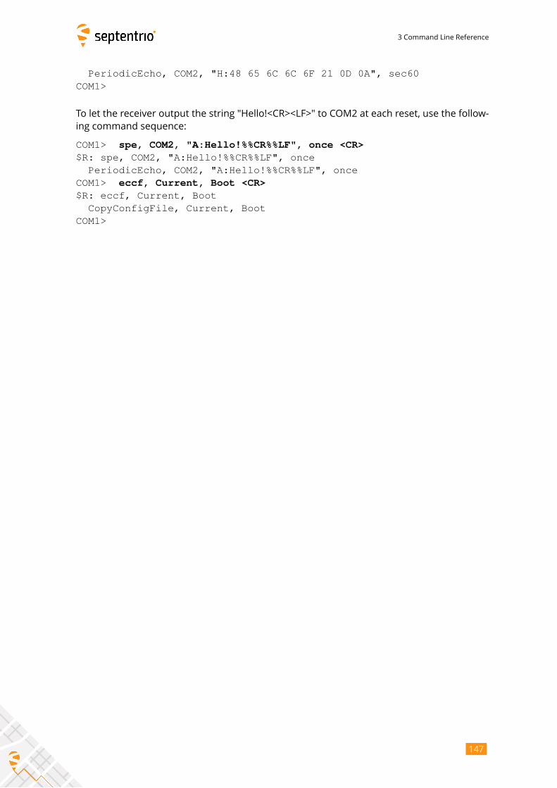
3 Command Line Reference
PeriodicEcho, COM2, "H:48 65 6C 6C 6F 21 0D 0A", sec60COM1>
To let the receiver output the string "Hello!<CR><LF>" to COM2 at each reset, use the follow-
ing command sequence:
COM1> spe, COM2, "A:Hello!%%CR%%LF", once <CR>$R: spe, COM2, "A:Hello!%%CR%%LF", once
PeriodicEcho, COM2, "A:Hello!%%CR%%LF", onceCOM1> eccf, Current, Boot <CR>$R: eccf, Current, Boot
CopyConfigFile, Current, BootCOM1>
147
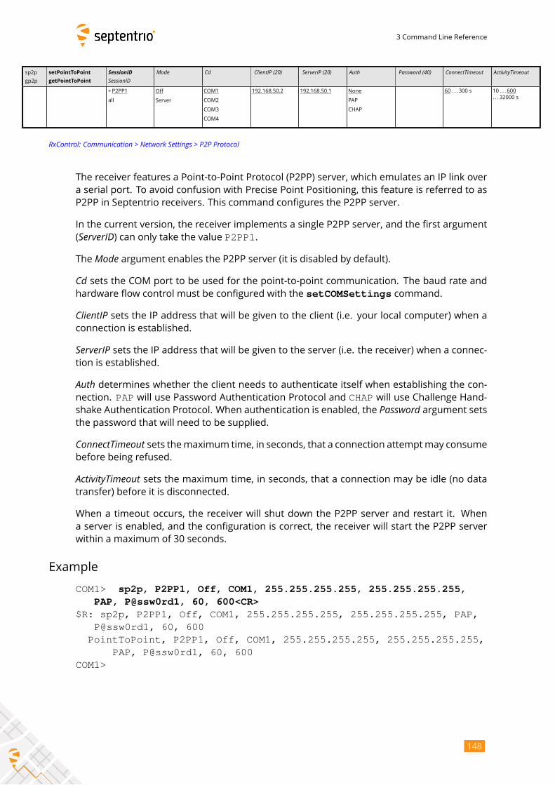
3 Command Line Reference
sp2p
gp2p
setPointToPoint
getPointToPoint
SessionIDSessionID
Mode Cd ClientIP (20) ServerIP (20) Auth Password (40) ConnectTimeout ActivityTimeout
+P2PP1
all
Off
Server
COM1
COM2
COM3
COM4
192.168.50.2 192.168.50.1 None
PAP
CHAP
60 . . . 300 s 10 . . . 600
. . . 32000 s
RxControl: Communication > Network Settings > P2P Protocol
The receiver features a Point-to-Point Protocol (P2PP) server, which emulates an IP link over
a serial port. To avoid confusion with Precise Point Positioning, this feature is referred to as
P2PP in Septentrio receivers. This command configures the P2PP server.
In the current version, the receiver implements a single P2PP server, and the first argument
(ServerID) can only take the value P2PP1.The Mode argument enables the P2PP server (it is disabled by default).Cd sets the COM port to be used for the point-to-point communication. The baud rate andhardware flow control must be configured with the setCOMSettings command.
ClientIP sets the IP address that will be given to the client (i.e. your local computer) when aconnection is established.
ServerIP sets the IP address that will be given to the server (i.e. the receiver) when a connec-tion is established.
Auth determines whether the client needs to authenticate itself when establishing the con-nection. PAP will use Password Authentication Protocol and CHAP will use Challenge Hand-shake Authentication Protocol. When authentication is enabled, the Password argument setsthe password that will need to be supplied.
ConnectTimeout sets themaximum time, in seconds, that a connection attemptmay consumebefore being refused.
ActivityTimeout sets the maximum time, in seconds, that a connection may be idle (no datatransfer) before it is disconnected.
When a timeout occurs, the receiver will shut down the P2PP server and restart it. When
a server is enabled, and the configuration is correct, the receiver will start the P2PP server
within a maximum of 30 seconds.
Example
COM1> sp2p, P2PP1, Off, COM1, 255.255.255.255, 255.255.255.255,PAP, P@ssw0rd1, 60, 600<CR>
$R: sp2p, P2PP1, Off, COM1, 255.255.255.255, 255.255.255.255, PAP,P@ssw0rd1, 60, 600
PointToPoint, P2PP1, Off, COM1, 255.255.255.255, 255.255.255.255,PAP, P@ssw0rd1, 60, 600
COM1>
148
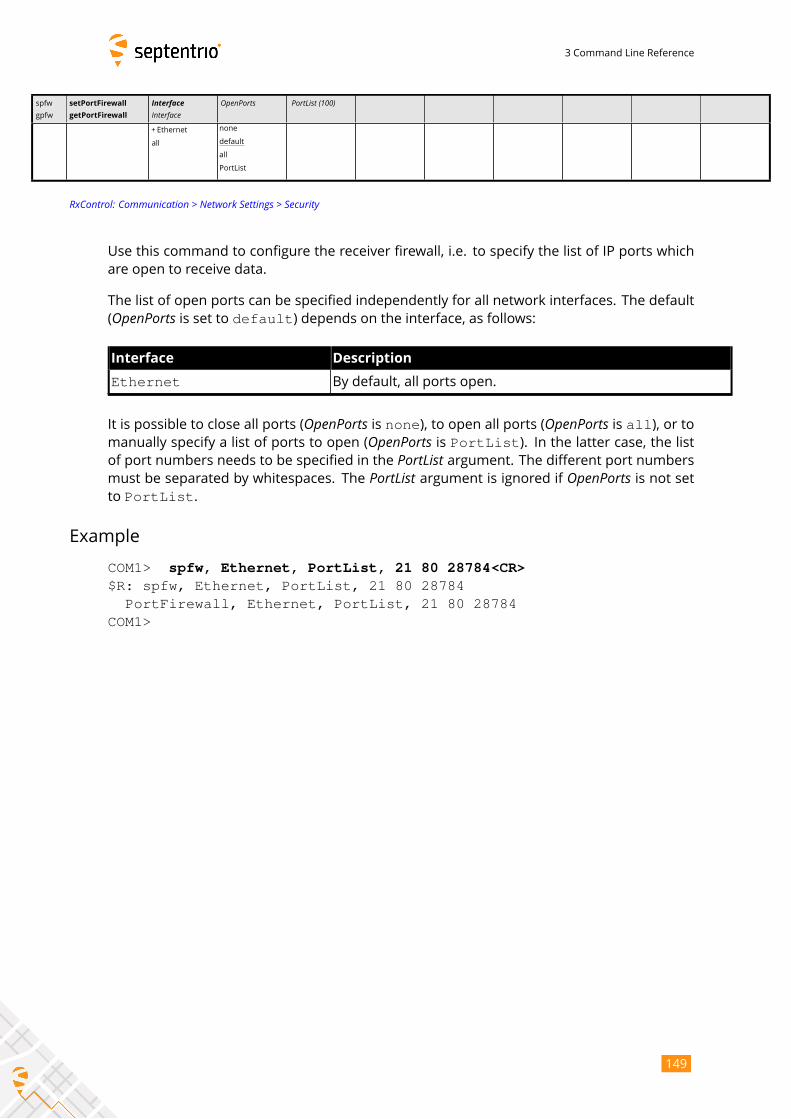
3 Command Line Reference
spfw
gpfw
setPortFirewall
getPortFirewall
InterfaceInterface
OpenPorts PortList (100)
+ Ethernet
all
none
default
all
PortList
RxControl: Communication > Network Settings > Security
Use this command to configure the receiver firewall, i.e. to specify the list of IP ports which
are open to receive data.
The list of open ports can be specified independently for all network interfaces. The default
(OpenPorts is set to default) depends on the interface, as follows:Interface Description
Ethernet By default, all ports open.
It is possible to close all ports (OpenPorts is none), to open all ports (OpenPorts is all), or tomanually specify a list of ports to open (OpenPorts is PortList). In the latter case, the listof port numbers needs to be specified in the PortList argument. The different port numbersmust be separated by whitespaces. The PortList argument is ignored if OpenPorts is not setto PortList.
Example
COM1> spfw, Ethernet, PortList, 21 80 28784<CR>$R: spfw, Ethernet, PortList, 21 80 28784
PortFirewall, Ethernet, PortList, 21 80 28784COM1>
149
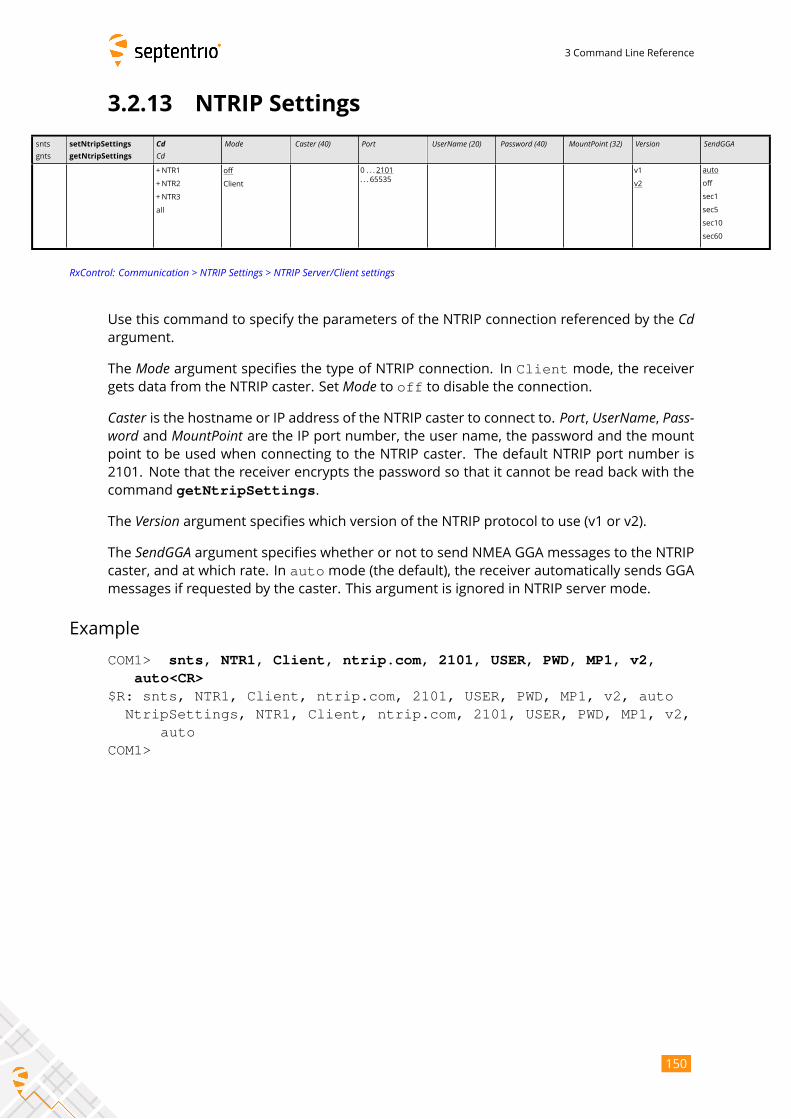
3 Command Line Reference
3.2.13 NTRIP Settings
snts
gnts
setNtripSettings
getNtripSettings
CdCd
Mode Caster (40) Port UserName (20) Password (40) MountPoint (32) Version SendGGA
+NTR1
+NTR2
+NTR3
all
off
Client
0 . . . 2101
. . . 65535
v1
v2
auto
off
sec1
sec5
sec10
sec60
RxControl: Communication > NTRIP Settings > NTRIP Server/Client settings
Use this command to specify the parameters of the NTRIP connection referenced by the Cdargument.
The Mode argument specifies the type of NTRIP connection. In Client mode, the receivergets data from the NTRIP caster. Set Mode to off to disable the connection.Caster is the hostname or IP address of the NTRIP caster to connect to. Port, UserName, Pass-word and MountPoint are the IP port number, the user name, the password and the mountpoint to be used when connecting to the NTRIP caster. The default NTRIP port number is
2101. Note that the receiver encrypts the password so that it cannot be read back with the
command getNtripSettings.
The Version argument specifies which version of the NTRIP protocol to use (v1 or v2).The SendGGA argument specifies whether or not to send NMEA GGA messages to the NTRIPcaster, and at which rate. In automode (the default), the receiver automatically sends GGAmessages if requested by the caster. This argument is ignored in NTRIP server mode.
Example
COM1> snts, NTR1, Client, ntrip.com, 2101, USER, PWD, MP1, v2,auto<CR>
$R: snts, NTR1, Client, ntrip.com, 2101, USER, PWD, MP1, v2, autoNtripSettings, NTR1, Client, ntrip.com, 2101, USER, PWD, MP1, v2,
autoCOM1>
150
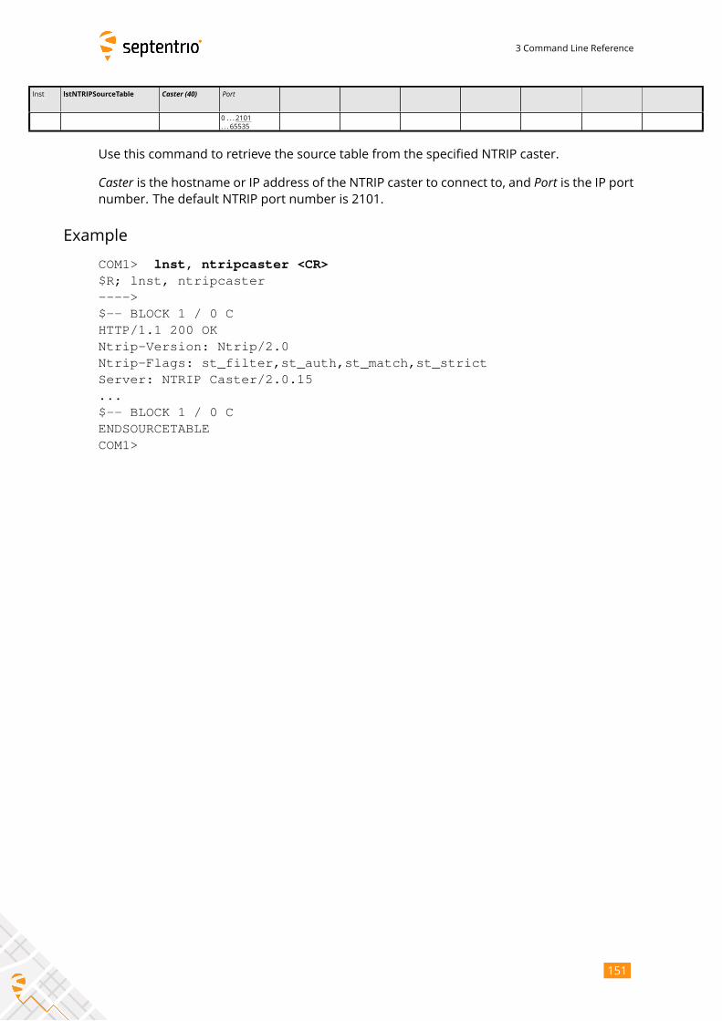
3 Command Line Reference
lnst lstNTRIPSourceTable Caster (40) Port
0 . . . 2101
. . . 65535
Use this command to retrieve the source table from the specified NTRIP caster.
Caster is the hostname or IP address of the NTRIP caster to connect to, and Port is the IP portnumber. The default NTRIP port number is 2101.
Example
COM1> lnst, ntripcaster <CR>$R; lnst, ntripcaster---->$-- BLOCK 1 / 0 CHTTP/1.1 200 OKNtrip-Version: Ntrip/2.0Ntrip-Flags: st_filter,st_auth,st_match,st_strictServer: NTRIP Caster/2.0.15...$-- BLOCK 1 / 0 CENDSOURCETABLECOM1>
151
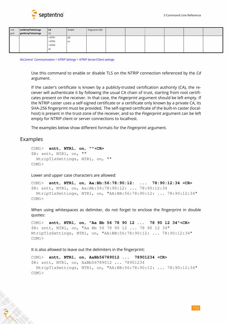
3 Command Line Reference
sntt
gntt
setNtripTlsSettings
getNtripTlsSettings
CdCd
Enable Fingerprint (96)
+NTR1
+NTR2
+NTR3
all
off
on
RxControl: Communication > NTRIP Settings > NTRIP Server/Client settings
Use this command to enable or disable TLS on the NTRIP connection referenced by the Cdargument.
If the caster’s certificate is known by a publicly-trusted certification authority (CA), the re-
ceiver will authenticate it by following the usual CA chain of trust, starting from root certifi-
cates present on the receiver. In that case, the Fingerprint argument should be left empty. Ifthe NTRIP caster uses a self-signed certificate or a certificate only known by a private CA, its
SHA-256 fingerprint must be provided. The self-signed certificate of the built-in caster (local-
host) is present in the trust-zone of the receiver, and so the Fingerprint argument can be leftempty for NTRIP client or server connections to localhost.
The examples below show different formats for the Fingerprint argument.Examples
COM1> sntt, NTR1, on, ""<CR>$R: sntt, NTR1, on, ""
NtripTlsSettings, NTR1, on, ""COM1>
Lower and upper case characters are allowed:
COM1> sntt, NTR1, on, Aa:Bb:56:78:90:12: ... 78:90:12:34 <CR>$R: sntt, NTR1, on, Aa:Bb:56:78:90:12: ... 78:90:12:34
NtripTlsSettings, NTR1, on, "AA:BB:56:78:90:12: ... 78:90:12:34"COM1>
When using whitespaces as delimiter, do not forget to enclose the fingerprint in double
quotes:
COM1> sntt, NTR1, on, "Aa Bb 56 78 90 12 ... 78 90 12 34"<CR>$R: sntt, NTR1, on, "Aa Bb 56 78 90 12 ... 78 90 12 34"NtripTlsSettings, NTR1, on, "AA:BB:56:78:90:12: ... 78:90:12:34"COM1>
It is also allowed to leave out the delimiters in the fingerprint:
COM1> sntt, NTR1, on, AaBb56789012 ... 78901234 <CR>$R: sntt, NTR1, on, AaBb56789012 ... 78901234
NtripTlsSettings, NTR1, on, "AA:BB:56:78:90:12: ... 78:90:12:34"COM1>
152
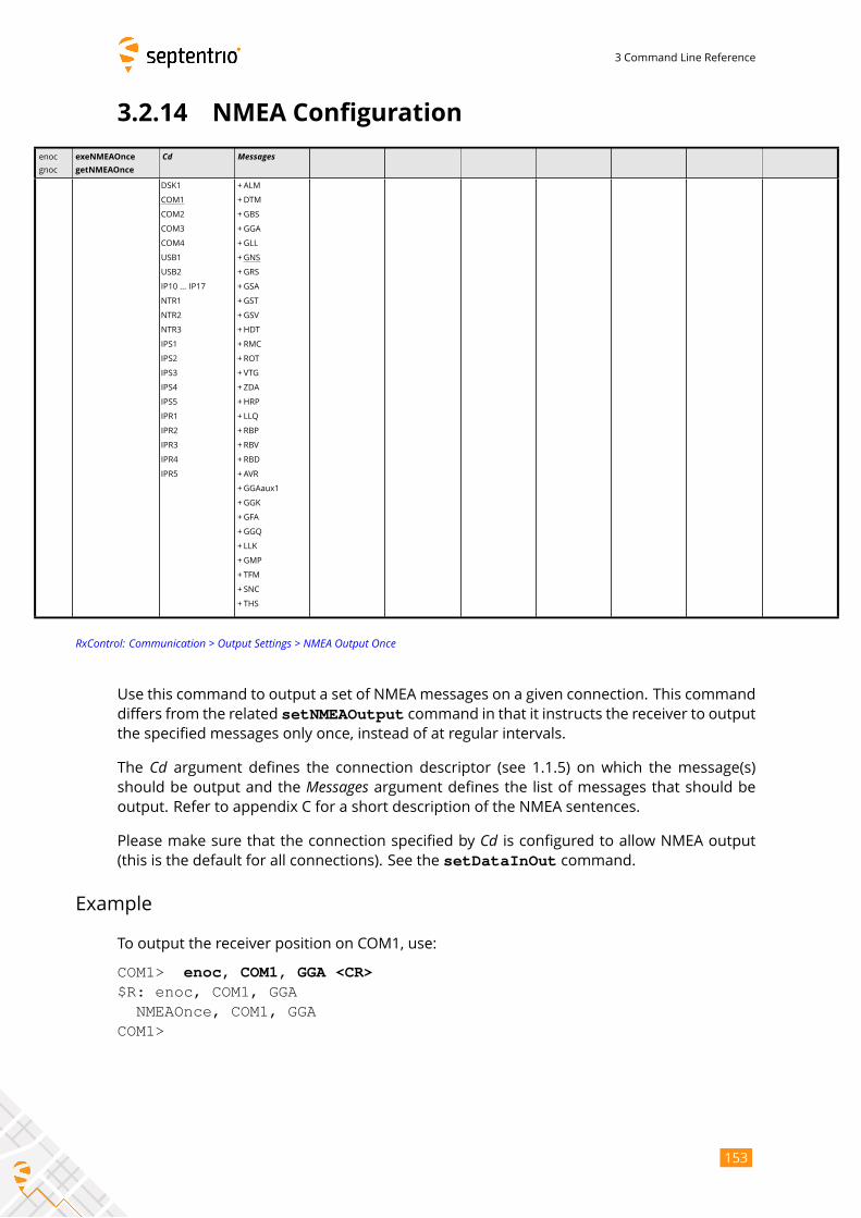
3 Command Line Reference
3.2.14 NMEA Configuration
enoc
gnoc
exeNMEAOnce
getNMEAOnce
Cd Messages
DSK1
COM1
COM2
COM3
COM4
USB1
USB2
IP10 ... IP17
NTR1
NTR2
NTR3
IPS1
IPS2
IPS3
IPS4
IPS5
IPR1
IPR2
IPR3
IPR4
IPR5
+ALM
+DTM
+GBS
+GGA
+GLL
+GNS
+GRS
+GSA
+GST
+GSV
+HDT
+RMC
+ROT
+VTG
+ZDA
+HRP
+ LLQ
+RBP
+RBV
+RBD
+AVR
+GGAaux1
+GGK
+GFA
+GGQ
+LLK
+GMP
+TFM
+SNC
+ THS
RxControl: Communication > Output Settings > NMEA Output Once
Use this command to output a set of NMEA messages on a given connection. This command
differs from the related setNMEAOutput command in that it instructs the receiver to outputthe specified messages only once, instead of at regular intervals.
The Cd argument defines the connection descriptor (see 1.1.5) on which the message(s)should be output and the Messages argument defines the list of messages that should beoutput. Refer to appendix C for a short description of the NMEA sentences.
Please make sure that the connection specified by Cd is configured to allow NMEA output(this is the default for all connections). See the setDataInOut command.
Example
To output the receiver position on COM1, use:
COM1> enoc, COM1, GGA <CR>$R: enoc, COM1, GGA
NMEAOnce, COM1, GGACOM1>
153
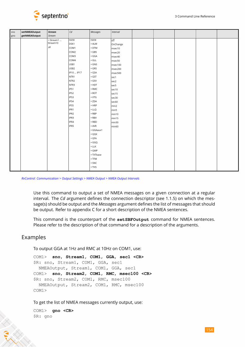
3 Command Line Reference
sno
gno
setNMEAOutput
getNMEAOutput
StreamStream
Cd Messages Interval
+ Stream1 ...
Stream10
all
none
DSK1
COM1
COM2
COM3
COM4
USB1
USB2
IP10 ... IP17
NTR1
NTR2
NTR3
IPS1
IPS2
IPS3
IPS4
IPS5
IPR1
IPR2
IPR3
IPR4
IPR5
none
+ALM
+DTM
+GBS
+GGA
+GLL
+GNS
+GRS
+GSA
+GST
+GSV
+HDT
+RMC
+ROT
+VTG
+ZDA
+HRP
+ LLQ
+RBP
+RBV
+RBD
+AVR
+GGAaux1
+GGK
+GFA
+GGQ
+LLK
+GMP
+TXTbase
+ TFM
+SNC
+ THS
off
OnChange
msec10
msec20
msec40
msec50
msec100
msec200
msec500
sec1
sec2
sec5
sec10
sec15
sec30
sec60
min2
min5
min10
min15
min30
min60
RxControl: Communication > Output Settings > NMEA Output > NMEA Output Intervals
Use this command to output a set of NMEA messages on a given connection at a regular
interval. The Cd argument defines the connection descriptor (see 1.1.5) on which the mes-sage(s) should be output and theMessages argument defines the list of messages that shouldbe output. Refer to appendix C for a short description of the NMEA sentences.
This command is the counterpart of the setSBFOutput command for NMEA sentences.Please refer to the description of that command for a description of the arguments.
Examples
To output GGA at 1Hz and RMC at 10Hz on COM1, use:
COM1> sno, Stream1, COM1, GGA, sec1 <CR>$R: sno, Stream1, COM1, GGA, sec1
NMEAOutput, Stream1, COM1, GGA, sec1COM1> sno, Stream2, COM1, RMC, msec100 <CR>$R: sno, Stream2, COM1, RMC, msec100
NMEAOutput, Stream2, COM1, RMC, msec100COM1>
To get the list of NMEA messages currently output, use:
COM1> gno <CR>$R: gno
154
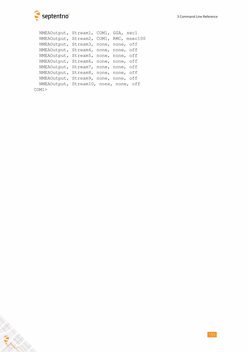
3 Command Line Reference
NMEAOutput, Stream1, COM1, GGA, sec1NMEAOutput, Stream2, COM1, RMC, msec100NMEAOutput, Stream3, none, none, offNMEAOutput, Stream4, none, none, offNMEAOutput, Stream5, none, none, offNMEAOutput, Stream6, none, none, offNMEAOutput, Stream7, none, none, offNMEAOutput, Stream8, none, none, offNMEAOutput, Stream9, none, none, offNMEAOutput, Stream10, none, none, off
COM1>
155
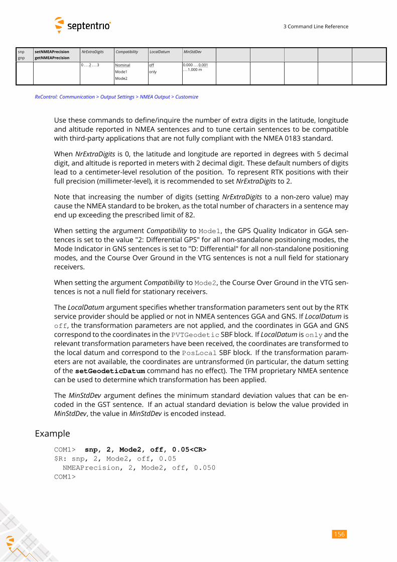
3 Command Line Reference
snp
gnp
setNMEAPrecision
getNMEAPrecision
NrExtraDigits Compatibility LocalDatum MinStdDev
0 . . . 2 . . . 3 Nominal
Mode1
Mode2
off
only
0.000 . . . 0.001
. . . 1.000 m
RxControl: Communication > Output Settings > NMEA Output > Customize
Use these commands to define/inquire the number of extra digits in the latitude, longitude
and altitude reported in NMEA sentences and to tune certain sentences to be compatible
with third-party applications that are not fully compliant with the NMEA 0183 standard.
When NrExtraDigits is 0, the latitude and longitude are reported in degrees with 5 decimaldigit, and altitude is reported in meters with 2 decimal digit. These default numbers of digits
lead to a centimeter-level resolution of the position. To represent RTK positions with their
full precision (millimeter-level), it is recommended to set NrExtraDigits to 2.Note that increasing the number of digits (setting NrExtraDigits to a non-zero value) maycause the NMEA standard to be broken, as the total number of characters in a sentence may
end up exceeding the prescribed limit of 82.
When setting the argument Compatibility to Mode1, the GPS Quality Indicator in GGA sen-tences is set to the value "2: Differential GPS" for all non-standalone positioning modes, the
Mode Indicator in GNS sentences is set to "D: Differential" for all non-standalone positioning
modes, and the Course Over Ground in the VTG sentences is not a null field for stationary
receivers.
When setting the argument Compatibility to Mode2, the Course Over Ground in the VTG sen-tences is not a null field for stationary receivers.
The LocalDatum argument specifies whether transformation parameters sent out by the RTKservice provider should be applied or not in NMEA sentences GGA and GNS. If LocalDatum isoff, the transformation parameters are not applied, and the coordinates in GGA and GNScorrespond to the coordinates in the PVTGeodetic SBF block. If LocalDatum is only and therelevant transformation parameters have been received, the coordinates are transformed to
the local datum and correspond to the PosLocal SBF block. If the transformation param-eters are not available, the coordinates are untransformed (in particular, the datum setting
of the setGeodeticDatum command has no effect). The TFM proprietary NMEA sentencecan be used to determine which transformation has been applied.
The MinStdDev argument defines the minimum standard deviation values that can be en-coded in the GST sentence. If an actual standard deviation is below the value provided inMinStdDev, the value in MinStdDev is encoded instead.
Example
COM1> snp, 2, Mode2, off, 0.05<CR>$R: snp, 2, Mode2, off, 0.05
NMEAPrecision, 2, Mode2, off, 0.050COM1>
156
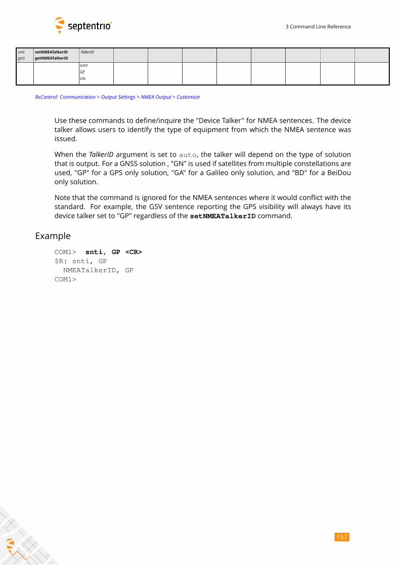
3 Command Line Reference
snti
gnti
setNMEATalkerID
getNMEATalkerID
TalkerID
auto
GP
GN
RxControl: Communication > Output Settings > NMEA Output > Customize
Use these commands to define/inquire the "Device Talker" for NMEA sentences. The device
talker allows users to identify the type of equipment from which the NMEA sentence was
issued.
When the TalkerID argument is set to auto, the talker will depend on the type of solutionthat is output. For a GNSS solution , "GN" is used if satellites frommultiple constellations are
used, "GP" for a GPS only solution, "GA" for a Galileo only solution, and "BD" for a BeiDou
only solution.
Note that the command is ignored for the NMEA sentences where it would conflict with the
standard. For example, the GSV sentence reporting the GPS visibility will always have its
device talker set to "GP" regardless of the setNMEATalkerID command.
Example
COM1> snti, GP <CR>$R: snti, GP
NMEATalkerID, GPCOM1>
157
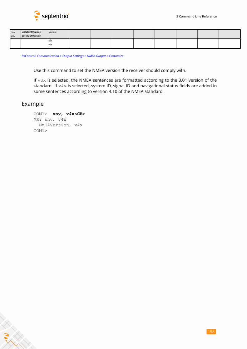
3 Command Line Reference
snv
gnv
setNMEAVersion
getNMEAVersion
Version
v3x
v4x
RxControl: Communication > Output Settings > NMEA Output > Customize
Use this command to set the NMEA version the receiver should comply with.
If v3x is selected, the NMEA sentences are formatted according to the 3.01 version of thestandard. If v4x is selected, system ID, signal ID and navigational status fields are added in
some sentences according to version 4.10 of the NMEA standard.
Example
COM1> snv, v4x<CR>$R: snv, v4x
NMEAVersion, v4xCOM1>
158
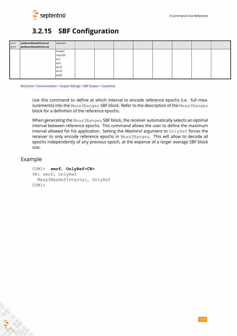
3 Command Line Reference
3.2.15 SBF Configuration
smrf
gmrf
setMeas3MaxRefInterval
getMeas3MaxRefInterval
MaxIntrvl
OnlyRef
msec500
sec1
sec5
sec10
sec30
sec60
RxControl: Communication > Output Settings > SBF Output > Customize
Use this command to define at which interval to encode reference epochs (i.e. full mea-
surements) into the Meas3Ranges SBF block. Refer to the description of the Meas3Rangesblock for a definition of the reference epochs.
When generating the Meas3Ranges SBF block, the receiver automatically selects an optimalinterval between reference epochs. This command allows the user to define the maximum
interval allowed for his application. Setting the MaxIntrvl argument to OnlyRef forces thereceiver to only encode reference epochs in Meas3Ranges. This will allow to decode allepochs independently of any previous epoch, at the expense of a larger average SBF block
size.
Example
COM1> smrf, OnlyRef<CR>$R: smrf, OnlyRef
Meas3MaxRefInterval, OnlyRefCOM1>
159
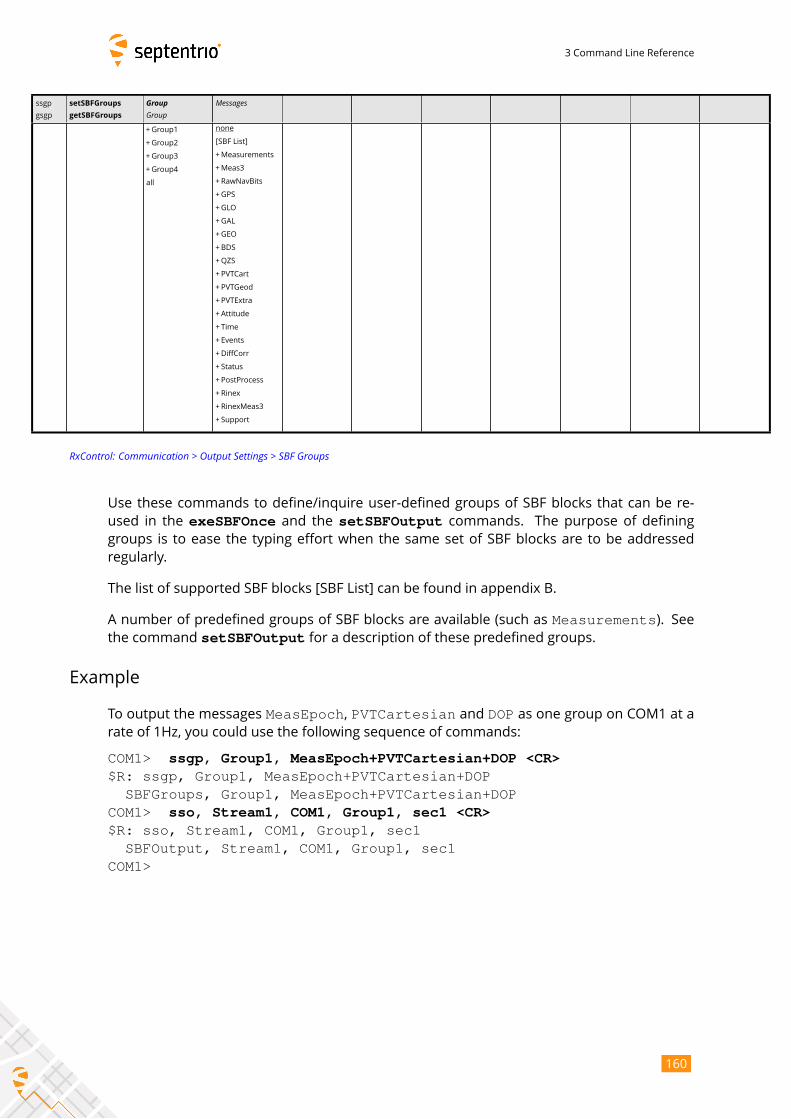
3 Command Line Reference
ssgp
gsgp
setSBFGroups
getSBFGroups
GroupGroup
Messages
+Group1
+Group2
+Group3
+Group4
all
none
[SBF List]
+Measurements
+Meas3
+RawNavBits
+GPS
+GLO
+GAL
+GEO
+BDS
+QZS
+PVTCart
+ PVTGeod
+PVTExtra
+ Attitude
+ Time
+ Events
+DiffCorr
+ Status
+ PostProcess
+ Rinex
+ RinexMeas3
+ Support
RxControl: Communication > Output Settings > SBF Groups
Use these commands to define/inquire user-defined groups of SBF blocks that can be re-
used in the exeSBFOnce and the setSBFOutput commands. The purpose of defininggroups is to ease the typing effort when the same set of SBF blocks are to be addressed
regularly.
The list of supported SBF blocks [SBF List] can be found in appendix B.
A number of predefined groups of SBF blocks are available (such as Measurements). Seethe command setSBFOutput for a description of these predefined groups.
Example
To output the messages MeasEpoch, PVTCartesian and DOP as one group on COM1 at arate of 1Hz, you could use the following sequence of commands:
COM1> ssgp, Group1, MeasEpoch+PVTCartesian+DOP <CR>$R: ssgp, Group1, MeasEpoch+PVTCartesian+DOP
SBFGroups, Group1, MeasEpoch+PVTCartesian+DOPCOM1> sso, Stream1, COM1, Group1, sec1 <CR>$R: sso, Stream1, COM1, Group1, sec1
SBFOutput, Stream1, COM1, Group1, sec1COM1>
160
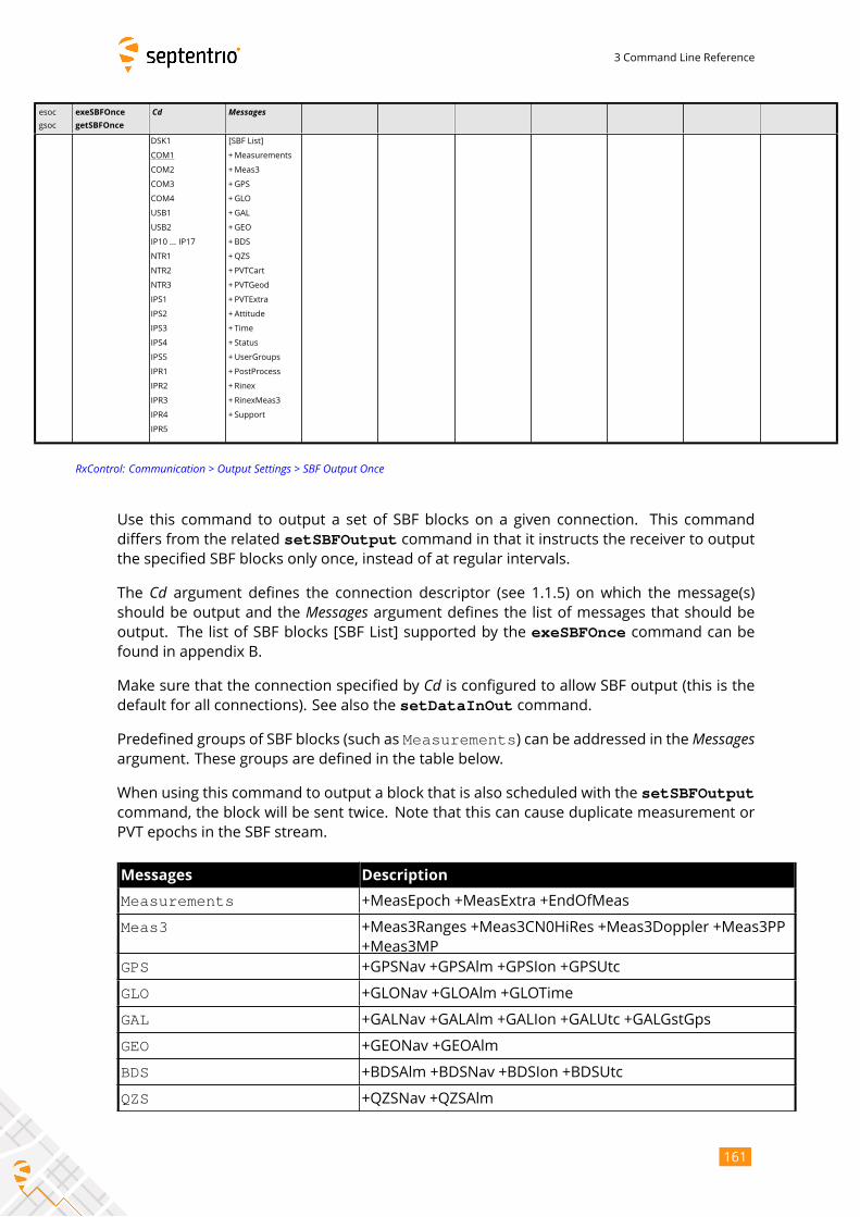
3 Command Line Reference
esoc
gsoc
exeSBFOnce
getSBFOnce
Cd Messages
DSK1
COM1
COM2
COM3
COM4
USB1
USB2
IP10 ... IP17
NTR1
NTR2
NTR3
IPS1
IPS2
IPS3
IPS4
IPS5
IPR1
IPR2
IPR3
IPR4
IPR5
[SBF List]
+Measurements
+Meas3
+GPS
+GLO
+GAL
+GEO
+BDS
+QZS
+PVTCart
+ PVTGeod
+PVTExtra
+ Attitude
+ Time
+ Status
+UserGroups
+ PostProcess
+ Rinex
+RinexMeas3
+ Support
RxControl: Communication > Output Settings > SBF Output Once
Use this command to output a set of SBF blocks on a given connection. This command
differs from the related setSBFOutput command in that it instructs the receiver to outputthe specified SBF blocks only once, instead of at regular intervals.
The Cd argument defines the connection descriptor (see 1.1.5) on which the message(s)should be output and the Messages argument defines the list of messages that should beoutput. The list of SBF blocks [SBF List] supported by the exeSBFOnce command can befound in appendix B.
Make sure that the connection specified by Cd is configured to allow SBF output (this is thedefault for all connections). See also the setDataInOut command.
Predefined groups of SBF blocks (such as Measurements) can be addressed in theMessagesargument. These groups are defined in the table below.
When using this command to output a block that is also scheduled with the setSBFOutputcommand, the block will be sent twice. Note that this can cause duplicate measurement or
PVT epochs in the SBF stream.
Messages Description
Measurements +MeasEpoch +MeasExtra +EndOfMeas
Meas3 +Meas3Ranges +Meas3CN0HiRes +Meas3Doppler +Meas3PP
+Meas3MP
GPS +GPSNav +GPSAlm +GPSIon +GPSUtc
GLO +GLONav +GLOAlm +GLOTime
GAL +GALNav +GALAlm +GALIon +GALUtc +GALGstGps
GEO +GEONav +GEOAlm
BDS +BDSAlm +BDSNav +BDSIon +BDSUtc
QZS +QZSNav +QZSAlm
161
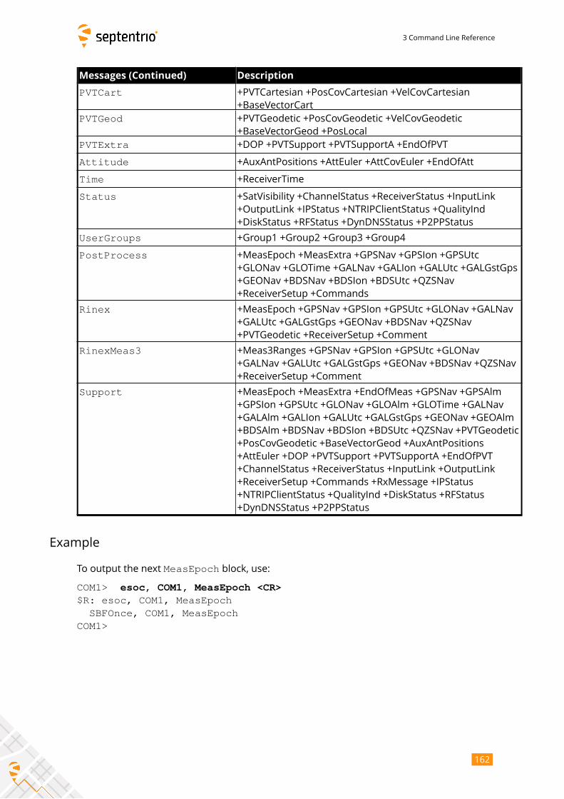
3 Command Line Reference
Messages (Continued) Description
PVTCart +PVTCartesian +PosCovCartesian +VelCovCartesian
+BaseVectorCart
PVTGeod +PVTGeodetic +PosCovGeodetic +VelCovGeodetic
+BaseVectorGeod +PosLocal
PVTExtra +DOP +PVTSupport +PVTSupportA +EndOfPVT
Attitude +AuxAntPositions +AttEuler +AttCovEuler +EndOfAtt
Time +ReceiverTime
Status +SatVisibility +ChannelStatus +ReceiverStatus +InputLink
+OutputLink +IPStatus +NTRIPClientStatus +QualityInd
+DiskStatus +RFStatus +DynDNSStatus +P2PPStatus
UserGroups +Group1 +Group2 +Group3 +Group4
PostProcess +MeasEpoch +MeasExtra +GPSNav +GPSIon +GPSUtc
+GLONav +GLOTime +GALNav +GALIon +GALUtc +GALGstGps
+GEONav +BDSNav +BDSIon +BDSUtc +QZSNav
+ReceiverSetup +Commands
Rinex +MeasEpoch +GPSNav +GPSIon +GPSUtc +GLONav +GALNav
+GALUtc +GALGstGps +GEONav +BDSNav +QZSNav
+PVTGeodetic +ReceiverSetup +Comment
RinexMeas3 +Meas3Ranges +GPSNav +GPSIon +GPSUtc +GLONav
+GALNav +GALUtc +GALGstGps +GEONav +BDSNav +QZSNav
+ReceiverSetup +Comment
Support +MeasEpoch +MeasExtra +EndOfMeas +GPSNav +GPSAlm
+GPSIon +GPSUtc +GLONav +GLOAlm +GLOTime +GALNav
+GALAlm +GALIon +GALUtc +GALGstGps +GEONav +GEOAlm
+BDSAlm +BDSNav +BDSIon +BDSUtc +QZSNav +PVTGeodetic
+PosCovGeodetic +BaseVectorGeod +AuxAntPositions
+AttEuler +DOP +PVTSupport +PVTSupportA +EndOfPVT
+ChannelStatus +ReceiverStatus +InputLink +OutputLink
+ReceiverSetup +Commands +RxMessage +IPStatus
+NTRIPClientStatus +QualityInd +DiskStatus +RFStatus
+DynDNSStatus +P2PPStatus
Example
To output the next MeasEpoch block, use:
COM1> esoc, COM1, MeasEpoch <CR>$R: esoc, COM1, MeasEpoch
SBFOnce, COM1, MeasEpochCOM1>
162
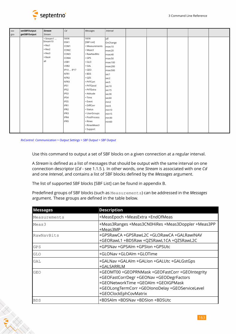
3 Command Line Reference
sso
gso
setSBFOutput
getSBFOutput
StreamStream
Cd Messages Interval
+ Stream1 ...
Stream10
+Res1
+Res2
+Res3
+Res4
all
none
DSK1
COM1
COM2
COM3
COM4
USB1
USB2
IP10 ... IP17
NTR1
NTR2
NTR3
IPS1
IPS2
IPS3
IPS4
IPS5
IPR1
IPR2
IPR3
IPR4
IPR5
none
[SBF List]
+Measurements
+Meas3
+RawNavBits
+GPS
+GLO
+GAL
+GEO
+BDS
+QZS
+PVTCart
+ PVTGeod
+PVTExtra
+ Attitude
+ Time
+ Event
+DiffCorr
+ Status
+UserGroups
+ PostProcess
+ Rinex
+RinexMeas3
+ Support
off
OnChange
msec10
msec20
msec40
msec50
msec100
msec200
msec500
sec1
sec2
sec5
sec10
sec15
sec30
sec60
min2
min5
min10
min15
min30
min60
RxControl: Communication > Output Settings > SBF Output > SBF Output
Use this command to output a set of SBF blocks on a given connection at a regular interval.
A Stream is defined as a list of messages that should be output with the same interval on oneconnection descriptor (Cd - see 1.1.5 ). In other words, one Stream is associated with one Cdand one Interval, and contains a list of SBF blocks defined by the Messages argument.The list of supported SBF blocks [SBF List] can be found in appendix B.
Predefined groups of SBF blocks (such as Measurements) can be addressed in theMessagesargument. These groups are defined in the table below.
Messages Description
Measurements +MeasEpoch +MeasExtra +EndOfMeas
Meas3 +Meas3Ranges +Meas3CN0HiRes +Meas3Doppler +Meas3PP
+Meas3MP
RawNavBits +GPSRawCA +GPSRawL2C +GLORawCA +GALRawINAV
+GEORawL1 +BDSRaw +QZSRawL1CA +QZSRawL2C
GPS +GPSNav +GPSAlm +GPSIon +GPSUtc
GLO +GLONav +GLOAlm +GLOTime
GAL +GALNav +GALAlm +GALIon +GALUtc +GALGstGps
+GALSARRLM
GEO +GEOMT00 +GEOPRNMask +GEOFastCorr +GEOIntegrity
+GEOFastCorrDegr +GEONav +GEODegrFactors
+GEONetworkTime +GEOAlm +GEOIGPMask
+GEOLongTermCorr +GEOIonoDelay +GEOServiceLevel
+GEOClockEphCovMatrix
BDS +BDSAlm +BDSNav +BDSIon +BDSUtc
163
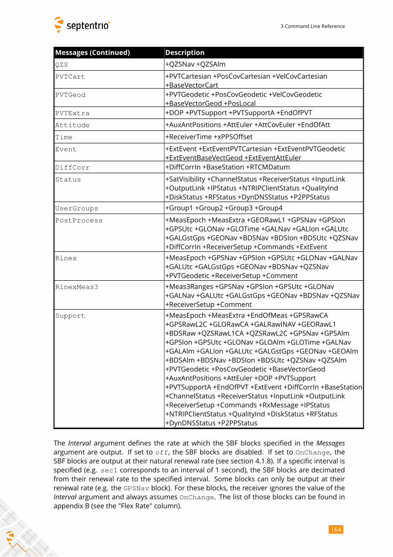
3 Command Line Reference
Messages (Continued) Description
QZS +QZSNav +QZSAlm
PVTCart +PVTCartesian +PosCovCartesian +VelCovCartesian
+BaseVectorCart
PVTGeod +PVTGeodetic +PosCovGeodetic +VelCovGeodetic
+BaseVectorGeod +PosLocal
PVTExtra +DOP +PVTSupport +PVTSupportA +EndOfPVT
Attitude +AuxAntPositions +AttEuler +AttCovEuler +EndOfAtt
Time +ReceiverTime +xPPSOffset
Event +ExtEvent +ExtEventPVTCartesian +ExtEventPVTGeodetic
+ExtEventBaseVectGeod +ExtEventAttEuler
DiffCorr +DiffCorrIn +BaseStation +RTCMDatum
Status +SatVisibility +ChannelStatus +ReceiverStatus +InputLink
+OutputLink +IPStatus +NTRIPClientStatus +QualityInd
+DiskStatus +RFStatus +DynDNSStatus +P2PPStatus
UserGroups +Group1 +Group2 +Group3 +Group4
PostProcess +MeasEpoch +MeasExtra +GEORawL1 +GPSNav +GPSIon
+GPSUtc +GLONav +GLOTime +GALNav +GALIon +GALUtc
+GALGstGps +GEONav +BDSNav +BDSIon +BDSUtc +QZSNav
+DiffCorrIn +ReceiverSetup +Commands +ExtEvent
Rinex +MeasEpoch +GPSNav +GPSIon +GPSUtc +GLONav +GALNav
+GALUtc +GALGstGps +GEONav +BDSNav +QZSNav
+PVTGeodetic +ReceiverSetup +Comment
RinexMeas3 +Meas3Ranges +GPSNav +GPSIon +GPSUtc +GLONav
+GALNav +GALUtc +GALGstGps +GEONav +BDSNav +QZSNav
+ReceiverSetup +Comment
Support +MeasEpoch +MeasExtra +EndOfMeas +GPSRawCA
+GPSRawL2C +GLORawCA +GALRawINAV +GEORawL1
+BDSRaw +QZSRawL1CA +QZSRawL2C +GPSNav +GPSAlm
+GPSIon +GPSUtc +GLONav +GLOAlm +GLOTime +GALNav
+GALAlm +GALIon +GALUtc +GALGstGps +GEONav +GEOAlm
+BDSAlm +BDSNav +BDSIon +BDSUtc +QZSNav +QZSAlm
+PVTGeodetic +PosCovGeodetic +BaseVectorGeod
+AuxAntPositions +AttEuler +DOP +PVTSupport
+PVTSupportA +EndOfPVT +ExtEvent +DiffCorrIn +BaseStation
+ChannelStatus +ReceiverStatus +InputLink +OutputLink
+ReceiverSetup +Commands +RxMessage +IPStatus
+NTRIPClientStatus +QualityInd +DiskStatus +RFStatus
+DynDNSStatus +P2PPStatus
The Interval argument defines the rate at which the SBF blocks specified in the Messagesargument are output. If set to off, the SBF blocks are disabled. If set to OnChange, theSBF blocks are output at their natural renewal rate (see section 4.1.8). If a specific interval is
specified (e.g. sec1 corresponds to an interval of 1 second), the SBF blocks are decimatedfrom their renewal rate to the specified interval. Some blocks can only be output at their
renewal rate (e.g. the GPSNav block). For these blocks, the receiver ignores the value of theInterval argument and always assumes OnChange. The list of those blocks can be found inappendix B (see the "Flex Rate" column).
164
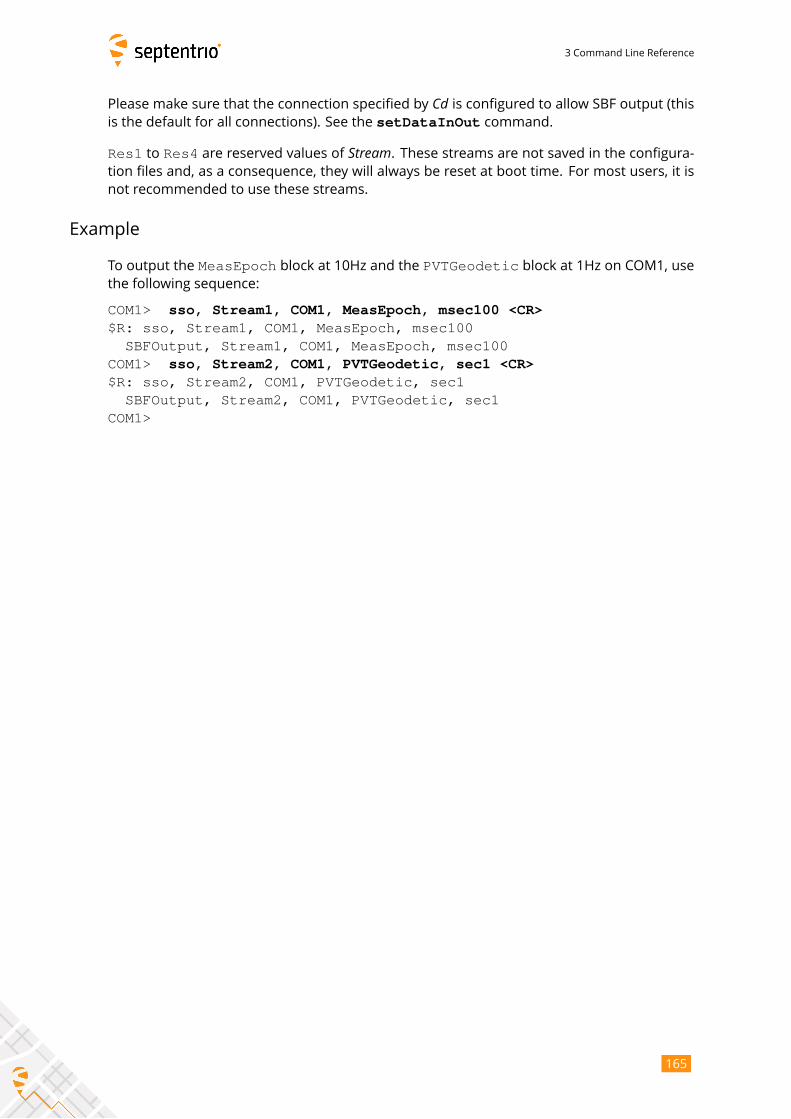
3 Command Line Reference
Please make sure that the connection specified by Cd is configured to allow SBF output (thisis the default for all connections). See the setDataInOut command.
Res1 to Res4 are reserved values of Stream. These streams are not saved in the configura-tion files and, as a consequence, they will always be reset at boot time. For most users, it is
not recommended to use these streams.
Example
To output the MeasEpoch block at 10Hz and the PVTGeodetic block at 1Hz on COM1, usethe following sequence:
COM1> sso, Stream1, COM1, MeasEpoch, msec100 <CR>$R: sso, Stream1, COM1, MeasEpoch, msec100
SBFOutput, Stream1, COM1, MeasEpoch, msec100COM1> sso, Stream2, COM1, PVTGeodetic, sec1 <CR>$R: sso, Stream2, COM1, PVTGeodetic, sec1
SBFOutput, Stream2, COM1, PVTGeodetic, sec1COM1>
165
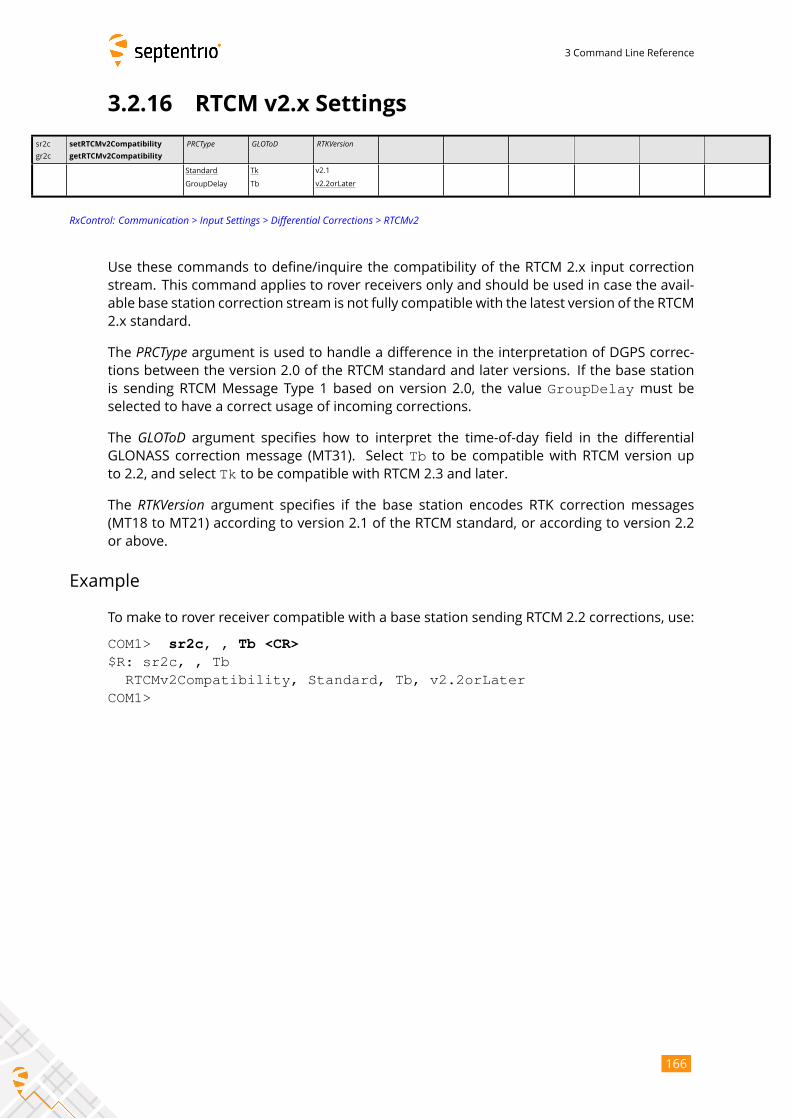
3 Command Line Reference
3.2.16 RTCM v2.x Settings
sr2c
gr2c
setRTCMv2Compatibility
getRTCMv2Compatibility
PRCType GLOToD RTKVersion
Standard
GroupDelay
Tk
Tb
v2.1
v2.2orLater
RxControl: Communication > Input Settings > Differential Corrections > RTCMv2
Use these commands to define/inquire the compatibility of the RTCM 2.x input correction
stream. This command applies to rover receivers only and should be used in case the avail-
able base station correction stream is not fully compatible with the latest version of the RTCM
2.x standard.
The PRCType argument is used to handle a difference in the interpretation of DGPS correc-tions between the version 2.0 of the RTCM standard and later versions. If the base station
is sending RTCM Message Type 1 based on version 2.0, the value GroupDelay must beselected to have a correct usage of incoming corrections.
The GLOToD argument specifies how to interpret the time-of-day field in the differentialGLONASS correction message (MT31). Select Tb to be compatible with RTCM version upto 2.2, and select Tk to be compatible with RTCM 2.3 and later.
The RTKVersion argument specifies if the base station encodes RTK correction messages(MT18 to MT21) according to version 2.1 of the RTCM standard, or according to version 2.2
or above.
Example
To make to rover receiver compatible with a base station sending RTCM 2.2 corrections, use:
COM1> sr2c, , Tb <CR>$R: sr2c, , Tb
RTCMv2Compatibility, Standard, Tb, v2.2orLaterCOM1>
166
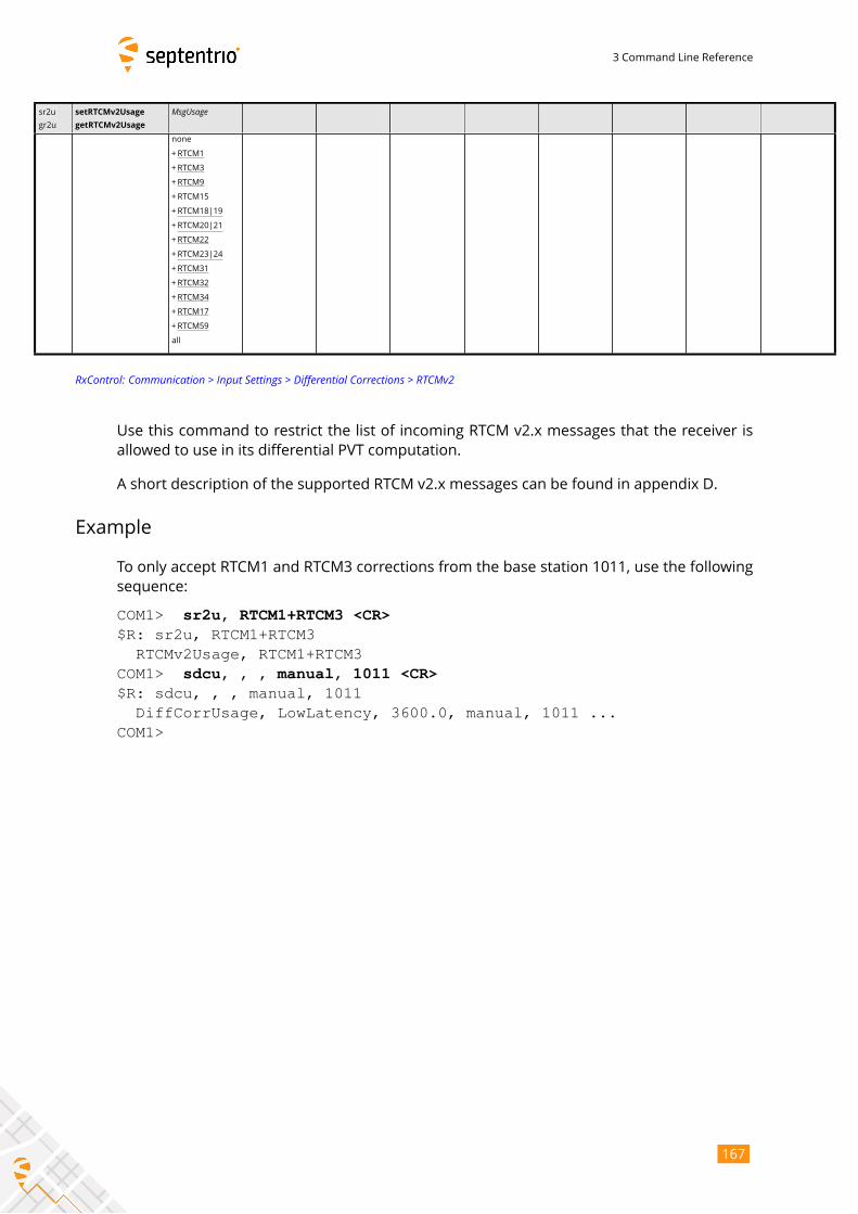
3 Command Line Reference
sr2u
gr2u
setRTCMv2Usage
getRTCMv2Usage
MsgUsagenone
+RTCM1
+RTCM3
+RTCM9
+RTCM15
+RTCM18|19
+RTCM20|21
+RTCM22
+RTCM23|24
+RTCM31
+RTCM32
+RTCM34
+RTCM17
+RTCM59
all
RxControl: Communication > Input Settings > Differential Corrections > RTCMv2
Use this command to restrict the list of incoming RTCM v2.x messages that the receiver is
allowed to use in its differential PVT computation.
A short description of the supported RTCM v2.x messages can be found in appendix D.
Example
To only accept RTCM1 and RTCM3 corrections from the base station 1011, use the following
sequence:
COM1> sr2u, RTCM1+RTCM3 <CR>$R: sr2u, RTCM1+RTCM3RTCMv2Usage, RTCM1+RTCM3
COM1> sdcu, , , manual, 1011 <CR>$R: sdcu, , , manual, 1011
DiffCorrUsage, LowLatency, 3600.0, manual, 1011 ...COM1>
167
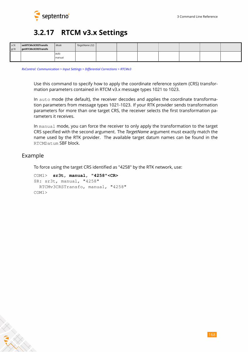
3 Command Line Reference
3.2.17 RTCM v3.x Settings
sr3t
gr3t
setRTCMv3CRSTransfo
getRTCMv3CRSTransfo
Mode TargetName (32)
auto
manual
RxControl: Communication > Input Settings > Differential Corrections > RTCMv3
Use this command to specify how to apply the coordinate reference system (CRS) transfor-
mation parameters contained in RTCM v3.x message types 1021 to 1023.
In auto mode (the default), the receiver decodes and applies the coordinate transforma-tion parameters from message types 1021-1023. If your RTK provider sends transformation
parameters for more than one target CRS, the receiver selects the first transformation pa-
rameters it receives.
In manual mode, you can force the receiver to only apply the transformation to the targetCRS specified with the second argument. The TargetName argument must exactly match thename used by the RTK provider. The available target datum names can be found in the
RTCMDatum SBF block.
Example
To force using the target CRS identified as "4258" by the RTK network, use:
COM1> sr3t, manual, "4258"<CR>$R: sr3t, manual, "4258"
RTCMv3CRSTransfo, manual, "4258"COM1>
168
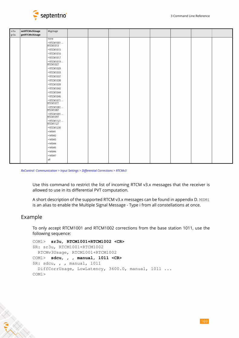
3 Command Line Reference
sr3u
gr3u
setRTCMv3Usage
getRTCMv3Usage
MsgUsagenone
+RTCM1001 ...
RTCM1013
+RTCM1015
+RTCM1016
+RTCM1017
+RTCM1019 ...
RTCM1027
+RTCM1029
+RTCM1033
+RTCM1037
+RTCM1038
+RTCM1039
+RTCM1042
+RTCM1044
+RTCM1046
+RTCM1071 ...
RTCM1077
+RTCM1081 ...
RTCM1087
+RTCM1091 ...
RTCM1097
+RTCM1121 ...
RTCM1127
+RTCM1230
+MSM1
+MSM2
+MSM3
+MSM4
+MSM5
+MSM6
+MSM7
all
RxControl: Communication > Input Settings > Differential Corrections > RTCMv3
Use this command to restrict the list of incoming RTCM v3.x messages that the receiver is
allowed to use in its differential PVT computation.
A short description of the supported RTCM v3.x messages can be found in appendix D. MSMiis an alias to enable the Multiple Signal Message - Type i from all constellations at once.
Example
To only accept RTCM1001 and RTCM1002 corrections from the base station 1011, use the
following sequence:
COM1> sr3u, RTCM1001+RTCM1002 <CR>$R: sr3u, RTCM1001+RTCM1002
RTCMv3Usage, RTCM1001+RTCM1002COM1> sdcu, , , manual, 1011 <CR>$R: sdcu, , , manual, 1011
DiffCorrUsage, LowLatency, 3600.0, manual, 1011 ...COM1>
169
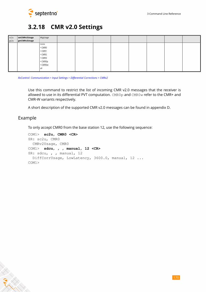
3 Command Line Reference
3.2.18 CMR v2.0 Settings
sc2u
gc2u
setCMRv2Usage
getCMRv2Usage
MsgUsagenone
+CMR0
+CMR1
+CMR2
+CMR3
+CMR0p
+CMR0w
all
RxControl: Communication > Input Settings > Differential Corrections > CMRv2
Use this command to restrict the list of incoming CMR v2.0 messages that the receiver is
allowed to use in its differential PVT computation. CMR0p and CMR0w refer to the CMR+ andCMR-W variants respectively.
A short description of the supported CMR v2.0 messages can be found in appendix D.
Example
To only accept CMR0 from the base station 12, use the following sequence:
COM1> sc2u, CMR0 <CR>$R: sc2u, CMR0
CMRv2Usage, CMR0COM1> sdcu, , , manual, 12 <CR>$R: sdcu, , , manual, 12
DiffCorrUsage, LowLatency, 3600.0, manual, 12 ...COM1>
170
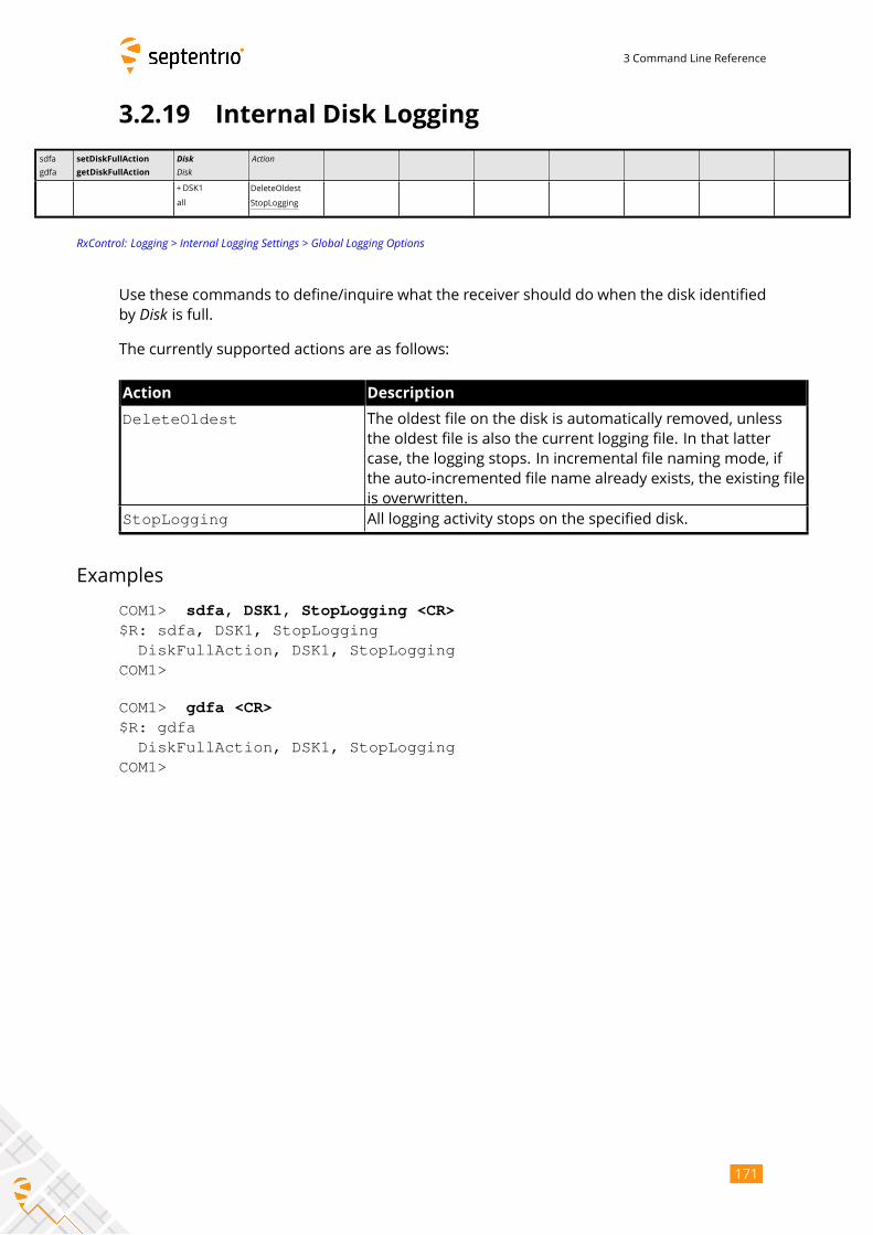
3 Command Line Reference
3.2.19 Internal Disk Logging
sdfa
gdfa
setDiskFullAction
getDiskFullAction
DiskDisk
Action
+DSK1
all
DeleteOldest
StopLogging
RxControl: Logging > Internal Logging Settings > Global Logging Options
Use these commands to define/inquire what the receiver should do when the disk identified
by Disk is full.The currently supported actions are as follows:
Action Description
DeleteOldest The oldest file on the disk is automatically removed, unless
the oldest file is also the current logging file. In that latter
case, the logging stops. In incremental file naming mode, if
the auto-incremented file name already exists, the existing file
is overwritten.
StopLogging All logging activity stops on the specified disk.
Examples
COM1> sdfa, DSK1, StopLogging <CR>$R: sdfa, DSK1, StopLogging
DiskFullAction, DSK1, StopLoggingCOM1>
COM1> gdfa <CR>$R: gdfa
DiskFullAction, DSK1, StopLoggingCOM1>
171
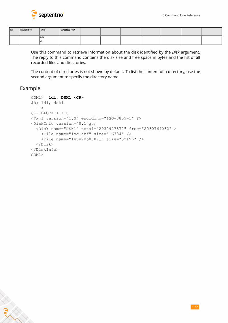
3 Command Line Reference
ldi lstDiskInfo Disk Directory (60)
DSK1
all
Use this command to retrieve information about the disk identified by the Disk argument.The reply to this command contains the disk size and free space in bytes and the list of all
recorded files and directories.
The content of directories is not shown by default. To list the content of a directory, use the
second argument to specify the directory name.
Example
COM1> ldi, DSK1 <CR>$R; ldi, dsk1---->$-- BLOCK 1 / 0<?xml version="1.0" encoding="ISO-8859-1" ?><DiskInfo version="0.1"gt;
<Disk name="DSK1" total="2030927872" free="2030764032" ><File name="log.sbf" size="16384" /><File name="leuv2050.07_" size="35196" />
</Disk></DiskInfo>COM1>
172
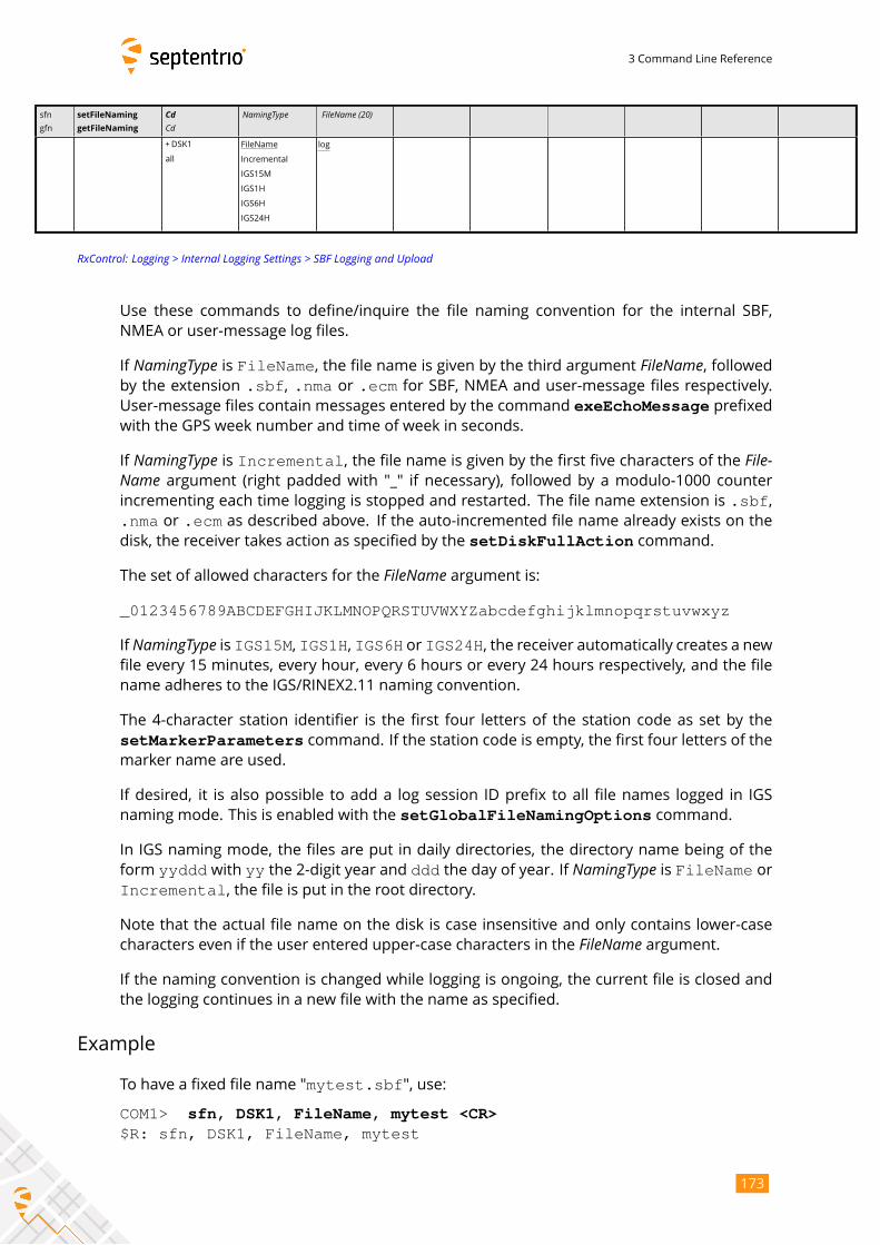
3 Command Line Reference
sfn
gfn
setFileNaming
getFileNaming
CdCd
NamingType FileName (20)
+DSK1
all
FileName
Incremental
IGS15M
IGS1H
IGS6H
IGS24H
log
RxControl: Logging > Internal Logging Settings > SBF Logging and Upload
Use these commands to define/inquire the file naming convention for the internal SBF,
NMEA or user-message log files.
If NamingType is FileName, the file name is given by the third argument FileName, followedby the extension .sbf, .nma or .ecm for SBF, NMEA and user-message files respectively.User-message files contain messages entered by the command exeEchoMessage prefixedwith the GPS week number and time of week in seconds.
If NamingType is Incremental, the file name is given by the first five characters of the File-Name argument (right padded with "_" if necessary), followed by a modulo-1000 counterincrementing each time logging is stopped and restarted. The file name extension is .sbf,.nma or .ecm as described above. If the auto-incremented file name already exists on thedisk, the receiver takes action as specified by the setDiskFullAction command.
The set of allowed characters for the FileName argument is:_0123456789ABCDEFGHIJKLMNOPQRSTUVWXYZabcdefghijklmnopqrstuvwxyz
If NamingType is IGS15M, IGS1H, IGS6H or IGS24H, the receiver automatically creates a newfile every 15 minutes, every hour, every 6 hours or every 24 hours respectively, and the file
name adheres to the IGS/RINEX2.11 naming convention.
The 4-character station identifier is the first four letters of the station code as set by the
setMarkerParameters command. If the station code is empty, the first four letters of themarker name are used.
If desired, it is also possible to add a log session ID prefix to all file names logged in IGS
naming mode. This is enabled with the setGlobalFileNamingOptions command.
In IGS naming mode, the files are put in daily directories, the directory name being of the
form yyddd with yy the 2-digit year and ddd the day of year. If NamingType is FileName orIncremental, the file is put in the root directory.
Note that the actual file name on the disk is case insensitive and only contains lower-case
characters even if the user entered upper-case characters in the FileName argument.If the naming convention is changed while logging is ongoing, the current file is closed and
the logging continues in a new file with the name as specified.
Example
To have a fixed file name "mytest.sbf", use:
COM1> sfn, DSK1, FileName, mytest <CR>$R: sfn, DSK1, FileName, mytest
173

3 Command Line Reference
FileNaming, DSK1, FileName, "mytest"COM1>
174
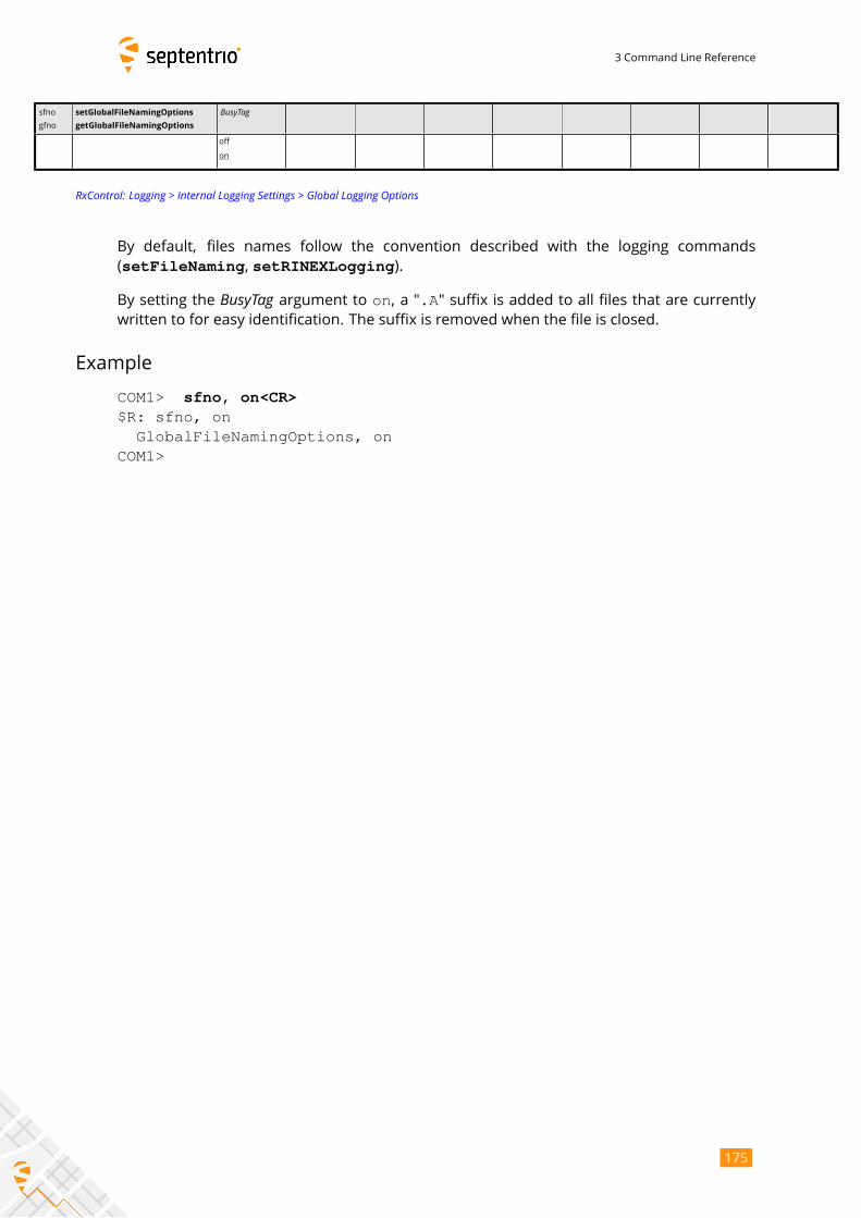
3 Command Line Reference
sfno
gfno
setGlobalFileNamingOptions
getGlobalFileNamingOptions
BusyTag
off
on
RxControl: Logging > Internal Logging Settings > Global Logging Options
By default, files names follow the convention described with the logging commands
(setFileNaming, setRINEXLogging).
By setting the BusyTag argument to on, a ".A" suffix is added to all files that are currentlywritten to for easy identification. The suffix is removed when the file is closed.
Example
COM1> sfno, on<CR>$R: sfno, on
GlobalFileNamingOptions, onCOM1>
175
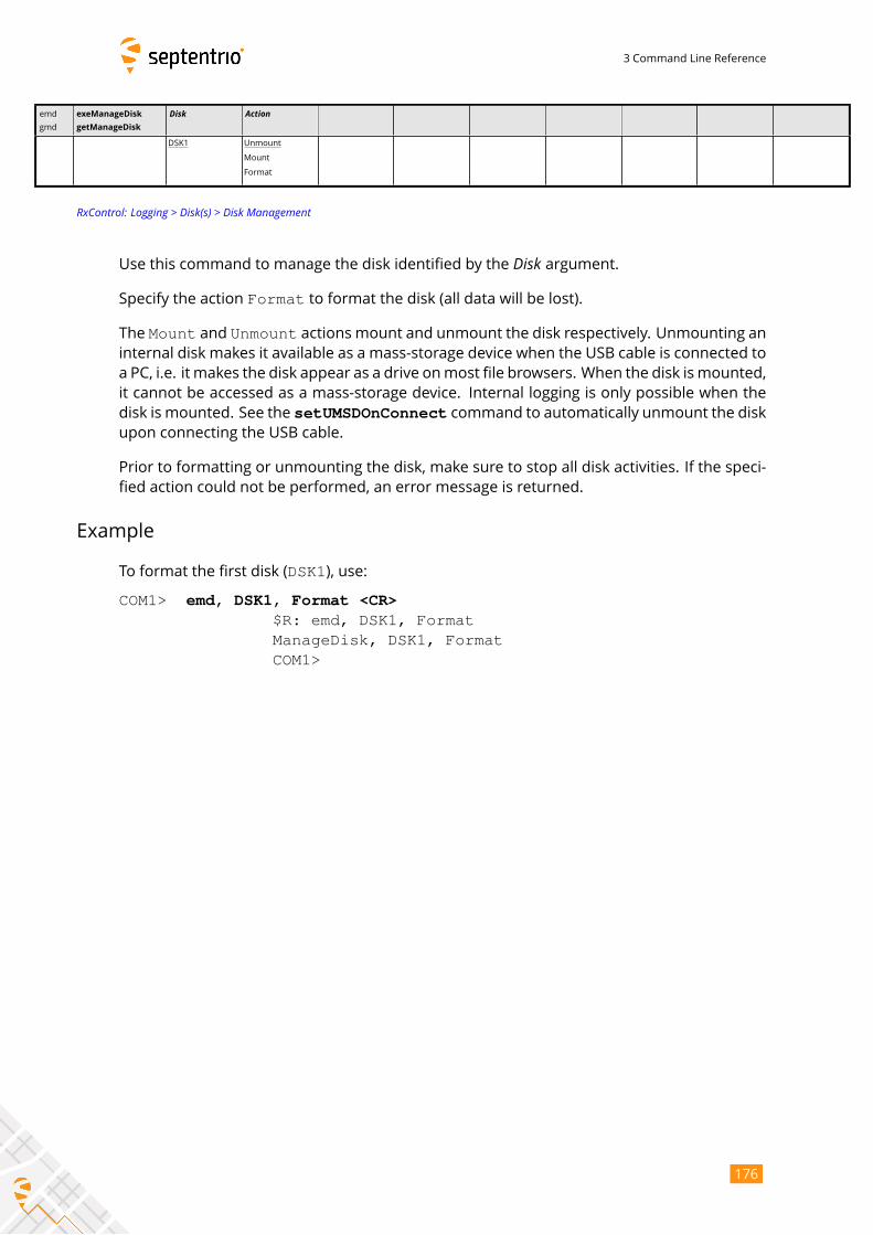
3 Command Line Reference
emd
gmd
exeManageDisk
getManageDisk
Disk Action
DSK1 Unmount
Mount
Format
RxControl: Logging > Disk(s) > Disk Management
Use this command to manage the disk identified by the Disk argument.Specify the action Format to format the disk (all data will be lost).
The Mount and Unmount actions mount and unmount the disk respectively. Unmounting aninternal disk makes it available as a mass-storage device when the USB cable is connected to
a PC, i.e. it makes the disk appear as a drive onmost file browsers. When the disk ismounted,
it cannot be accessed as a mass-storage device. Internal logging is only possible when the
disk is mounted. See the setUMSDOnConnect command to automatically unmount the diskupon connecting the USB cable.
Prior to formatting or unmounting the disk, make sure to stop all disk activities. If the speci-
fied action could not be performed, an error message is returned.
Example
To format the first disk (DSK1), use:
COM1> emd, DSK1, Format <CR>$R: emd, DSK1, FormatManageDisk, DSK1, FormatCOM1>
176
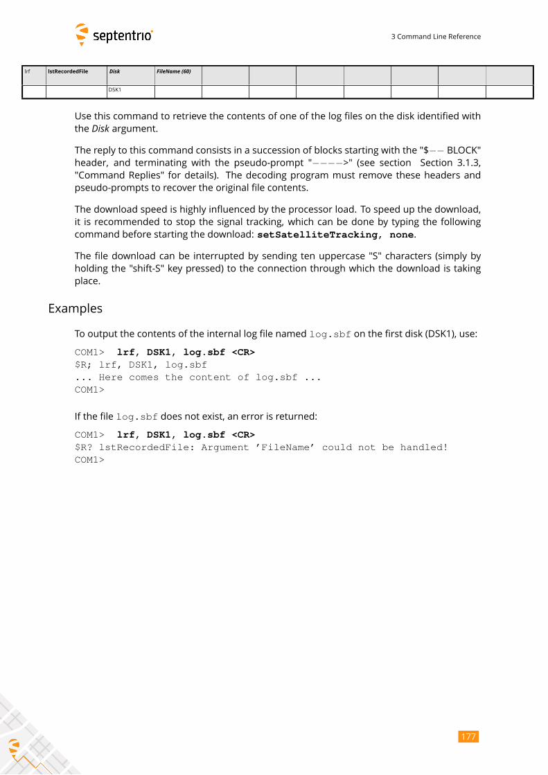
3 Command Line Reference
lrf lstRecordedFile Disk FileName (60)
DSK1
Use this command to retrieve the contents of one of the log files on the disk identified with
the Disk argument.The reply to this command consists in a succession of blocks starting with the "$−− BLOCK"header, and terminating with the pseudo-prompt "−−−−>" (see section Section 3.1.3,
"Command Replies" for details). The decoding program must remove these headers and
pseudo-prompts to recover the original file contents.
The download speed is highly influenced by the processor load. To speed up the download,
it is recommended to stop the signal tracking, which can be done by typing the following
command before starting the download: setSatelliteTracking, none.
The file download can be interrupted by sending ten uppercase "S" characters (simply by
holding the "shift-S" key pressed) to the connection through which the download is taking
place.
Examples
To output the contents of the internal log file named log.sbf on the first disk (DSK1), use:
COM1> lrf, DSK1, log.sbf <CR>$R; lrf, DSK1, log.sbf... Here comes the content of log.sbf ...COM1>
If the file log.sbf does not exist, an error is returned:
COM1> lrf, DSK1, log.sbf <CR>$R? lstRecordedFile: Argument ’FileName’ could not be handled!COM1>
177
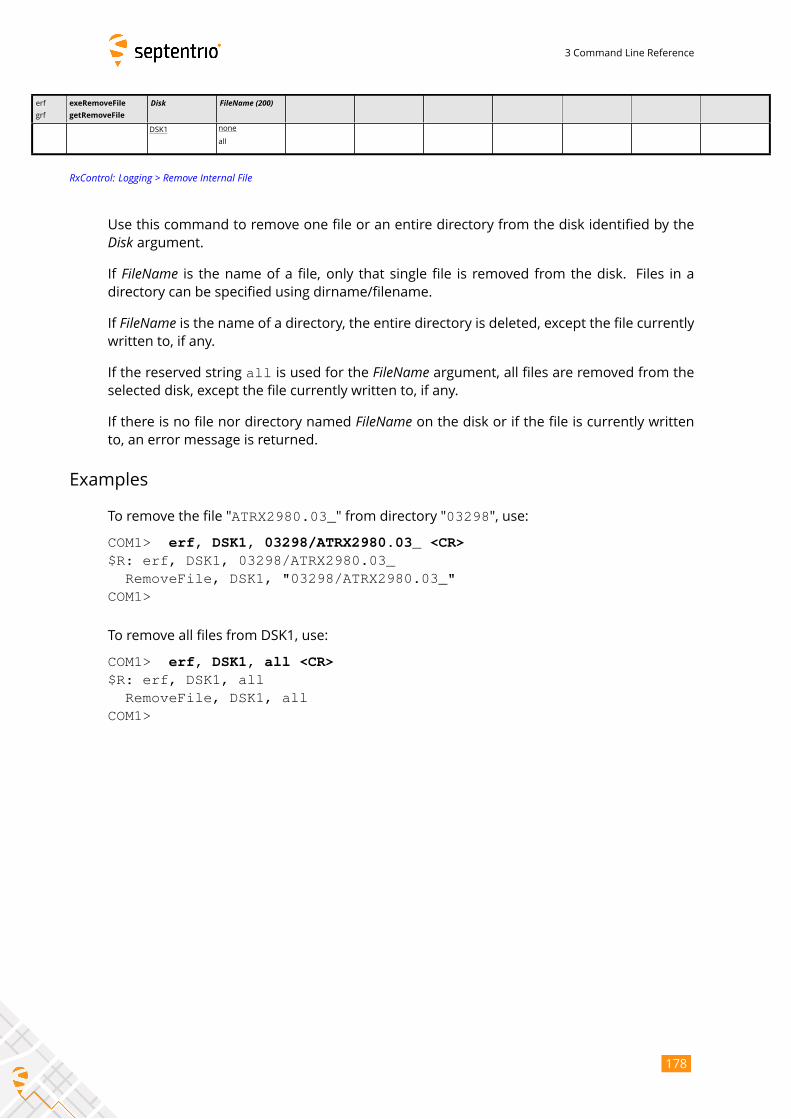
3 Command Line Reference
erf
grf
exeRemoveFile
getRemoveFile
Disk FileName (200)
DSK1 none
all
RxControl: Logging > Remove Internal File
Use this command to remove one file or an entire directory from the disk identified by theDisk argument.If FileName is the name of a file, only that single file is removed from the disk. Files in adirectory can be specified using dirname/filename.
If FileName is the name of a directory, the entire directory is deleted, except the file currentlywritten to, if any.
If the reserved string all is used for the FileName argument, all files are removed from theselected disk, except the file currently written to, if any.
If there is no file nor directory named FileName on the disk or if the file is currently writtento, an error message is returned.
Examples
To remove the file "ATRX2980.03_" from directory "03298", use:
COM1> erf, DSK1, 03298/ATRX2980.03_ <CR>$R: erf, DSK1, 03298/ATRX2980.03_
RemoveFile, DSK1, "03298/ATRX2980.03_"COM1>
To remove all files from DSK1, use:
COM1> erf, DSK1, all <CR>$R: erf, DSK1, all
RemoveFile, DSK1, allCOM1>
178
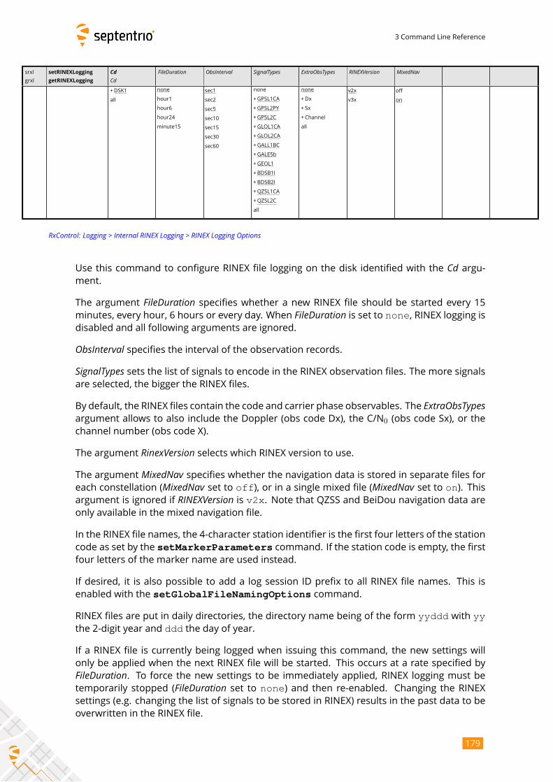
3 Command Line Reference
srxl
grxl
setRINEXLogging
getRINEXLogging
CdCd
FileDuration ObsInterval SignalTypes ExtraObsTypes RINEXVersion MixedNav
+DSK1
all
none
hour1
hour6
hour24
minute15
sec1
sec2
sec5
sec10
sec15
sec30
sec60
none
+GPSL1CA
+GPSL2PY
+GPSL2C
+GLOL1CA
+GLOL2CA
+GALL1BC
+GALE5b
+GEOL1
+BDSB1I
+BDSB2I
+QZSL1CA
+QZSL2C
all
none
+Dx
+ Sx
+Channel
all
v2x
v3x
off
on
RxControl: Logging > Internal RINEX Logging > RINEX Logging Options
Use this command to configure RINEX file logging on the disk identified with the Cd argu-ment.
The argument FileDuration specifies whether a new RINEX file should be started every 15minutes, every hour, 6 hours or every day. When FileDuration is set to none, RINEX logging isdisabled and all following arguments are ignored.
ObsInterval specifies the interval of the observation records.SignalTypes sets the list of signals to encode in the RINEX observation files. The more signalsare selected, the bigger the RINEX files.
By default, the RINEX files contain the code and carrier phase observables. The ExtraObsTypesargument allows to also include the Doppler (obs code Dx), the C/N0 (obs code Sx), or the
channel number (obs code X).
The argument RinexVersion selects which RINEX version to use.The argument MixedNav specifies whether the navigation data is stored in separate files foreach constellation (MixedNav set to off), or in a single mixed file (MixedNav set to on). Thisargument is ignored if RINEXVersion is v2x. Note that QZSS and BeiDou navigation data areonly available in the mixed navigation file.
In the RINEX file names, the 4-character station identifier is the first four letters of the station
code as set by the setMarkerParameters command. If the station code is empty, the firstfour letters of the marker name are used instead.
If desired, it is also possible to add a log session ID prefix to all RINEX file names. This is
enabled with the setGlobalFileNamingOptions command.
RINEX files are put in daily directories, the directory name being of the form yyddd with yythe 2-digit year and ddd the day of year.
If a RINEX file is currently being logged when issuing this command, the new settings will
only be applied when the next RINEX file will be started. This occurs at a rate specified byFileDuration. To force the new settings to be immediately applied, RINEX logging must betemporarily stopped (FileDuration set to none) and then re-enabled. Changing the RINEXsettings (e.g. changing the list of signals to be stored in RINEX) results in the past data to be
overwritten in the RINEX file.
179
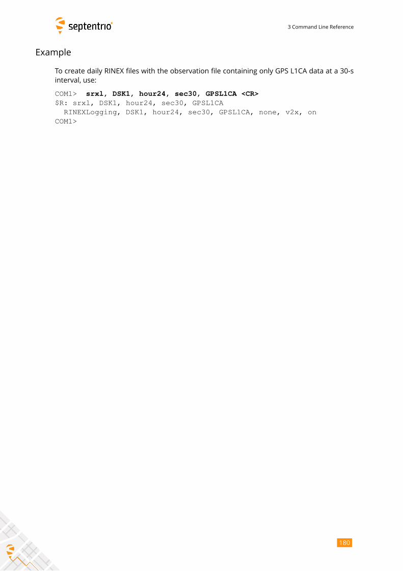
3 Command Line Reference
Example
To create daily RINEX files with the observation file containing only GPS L1CA data at a 30-s
interval, use:
COM1> srxl, DSK1, hour24, sec30, GPSL1CA <CR>$R: srxl, DSK1, hour24, sec30, GPSL1CA
RINEXLogging, DSK1, hour24, sec30, GPSL1CA, none, v2x, onCOM1>
180
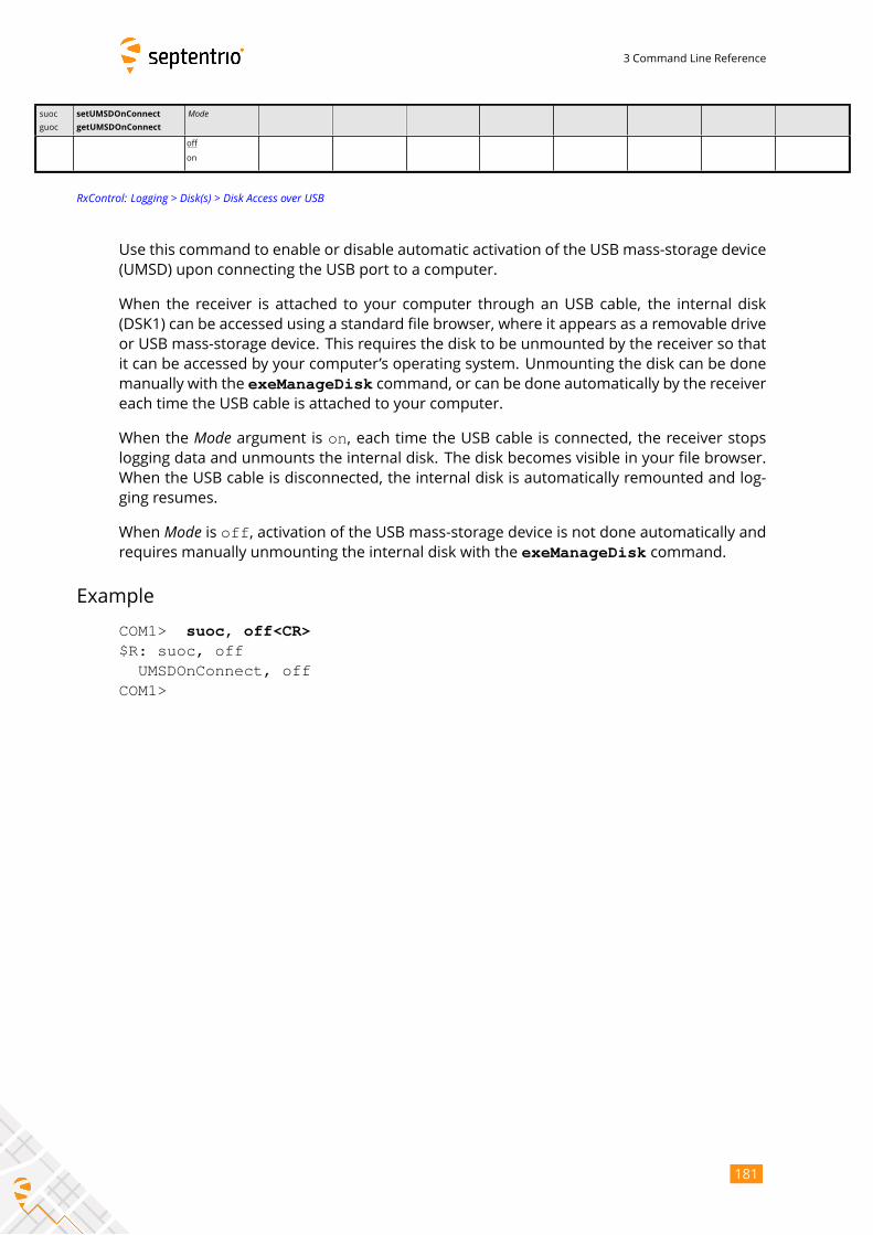
3 Command Line Reference
suoc
guoc
setUMSDOnConnect
getUMSDOnConnect
Mode
off
on
RxControl: Logging > Disk(s) > Disk Access over USB
Use this command to enable or disable automatic activation of the USB mass-storage device
(UMSD) upon connecting the USB port to a computer.
When the receiver is attached to your computer through an USB cable, the internal disk
(DSK1) can be accessed using a standard file browser, where it appears as a removable drive
or USB mass-storage device. This requires the disk to be unmounted by the receiver so that
it can be accessed by your computer’s operating system. Unmounting the disk can be done
manually with the exeManageDisk command, or can be done automatically by the receivereach time the USB cable is attached to your computer.
When the Mode argument is on, each time the USB cable is connected, the receiver stopslogging data and unmounts the internal disk. The disk becomes visible in your file browser.
When the USB cable is disconnected, the internal disk is automatically remounted and log-
ging resumes.
When Mode is off, activation of the USB mass-storage device is not done automatically andrequires manually unmounting the internal disk with the exeManageDisk command.
Example
COM1> suoc, off<CR>$R: suoc, off
UMSDOnConnect, offCOM1>
181
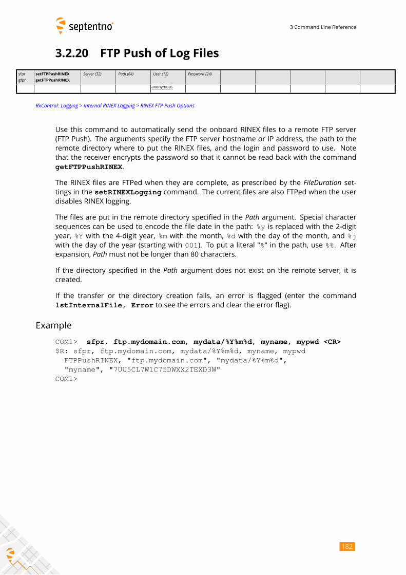
3 Command Line Reference
3.2.20 FTP Push of Log Files
sfpr
gfpr
setFTPPushRINEX
getFTPPushRINEX
Server (32) Path (64) User (12) Password (24)anonymous
RxControl: Logging > Internal RINEX Logging > RINEX FTP Push Options
Use this command to automatically send the onboard RINEX files to a remote FTP server
(FTP Push). The arguments specify the FTP server hostname or IP address, the path to the
remote directory where to put the RINEX files, and the login and password to use. Note
that the receiver encrypts the password so that it cannot be read back with the command
getFTPPushRINEX.
The RINEX files are FTPed when they are complete, as prescribed by the FileDuration set-tings in the setRINEXLogging command. The current files are also FTPed when the userdisables RINEX logging.
The files are put in the remote directory specified in the Path argument. Special charactersequences can be used to encode the file date in the path: %y is replaced with the 2-digityear, %Y with the 4-digit year, %m with the month, %d with the day of the month, and %jwith the day of the year (starting with 001). To put a literal "%" in the path, use %%. Afterexpansion, Pathmust not be longer than 80 characters.If the directory specified in the Path argument does not exist on the remote server, it iscreated.
If the transfer or the directory creation fails, an error is flagged (enter the command
lstInternalFile, Error to see the errors and clear the error flag).
Example
COM1> sfpr, ftp.mydomain.com, mydata/%Y%m%d, myname, mypwd <CR>$R: sfpr, ftp.mydomain.com, mydata/%Y%m%d, myname, mypwd
FTPPushRINEX, "ftp.mydomain.com", "mydata/%Y%m%d","myname", "7UU5CL7W1C75DWXX2TEXD3W"
COM1>
182
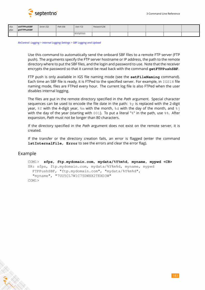
3 Command Line Reference
sfps
gfps
setFTPPushSBF
getFTPPushSBF
Server (32) Path (64) User (12) Password (24)anonymous
RxControl: Logging > Internal Logging Settings > SBF Logging and Upload
Use this command to automatically send the onboard SBF files to a remote FTP server (FTP
push). The arguments specify the FTP server hostname or IP address, the path to the remote
directory where to put the SBF files, and the login and password to use. Note that the receiver
encrypts the password so that it cannot be read back with the command getFTPPushSBF.
FTP push is only available in IGS file naming mode (see the setFileNaming command).Each time an SBF file is ready, it is FTPed to the specified server. For example, in IGS1H file
naming mode, files are FTPed every hour. The current log file is also FTPed when the user
disables internal logging.
The files are put in the remote directory specified in the Path argument. Special charactersequences can be used to encode the file date in the path: %y is replaced with the 2-digityear, %Y with the 4-digit year, %m with the month, %d with the day of the month, and %jwith the day of the year (starting with 001). To put a literal "%" in the path, use %%. Afterexpansion, Pathmust not be longer than 80 characters.If the directory specified in the Path argument does not exist on the remote server, it iscreated.
If the transfer or the directory creation fails, an error is flagged (enter the command
lstInternalFile, Error to see the errors and clear the error flag).
Example
COM1> sfps, ftp.mydomain.com, mydata/%Y%m%d, myname, mypwd <CR>$R: sfps, ftp.mydomain.com, mydata/%Y%m%d, myname, mypwd
FTPPushSBF, "ftp.mydomain.com", "mydata/%Y%m%d","myname", "7UU5CL7W1C75DWXX2TEXD3W"
COM1>
183
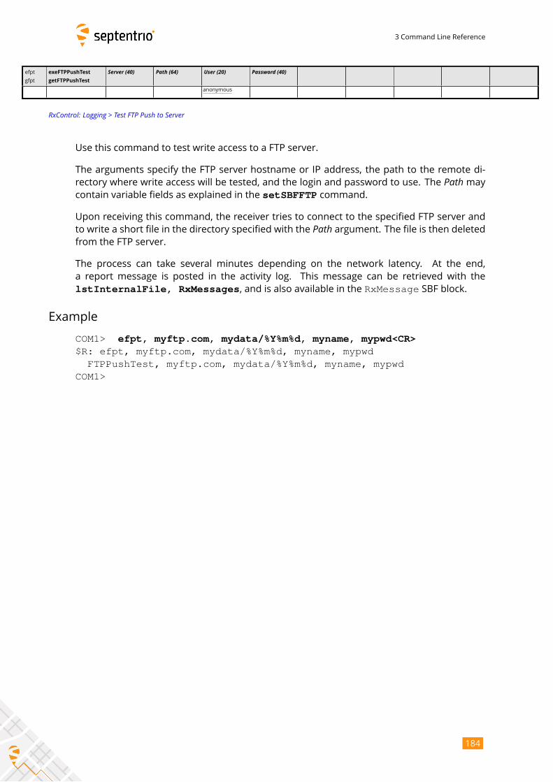
3 Command Line Reference
efpt
gfpt
exeFTPPushTest
getFTPPushTest
Server (40) Path (64) User (20) Password (40)
anonymous
RxControl: Logging > Test FTP Push to Server
Use this command to test write access to a FTP server.
The arguments specify the FTP server hostname or IP address, the path to the remote di-
rectory where write access will be tested, and the login and password to use. The Path maycontain variable fields as explained in the setSBFFTP command.
Upon receiving this command, the receiver tries to connect to the specified FTP server and
to write a short file in the directory specified with the Path argument. The file is then deletedfrom the FTP server.
The process can take several minutes depending on the network latency. At the end,
a report message is posted in the activity log. This message can be retrieved with the
lstInternalFile, RxMessages, and is also available in the RxMessage SBF block.
Example
COM1> efpt, myftp.com, mydata/%Y%m%d, myname, mypwd<CR>$R: efpt, myftp.com, mydata/%Y%m%d, myname, mypwd
FTPPushTest, myftp.com, mydata/%Y%m%d, myname, mypwdCOM1>
184
4 SBF Reference
Chapter 4
SBF Reference
185
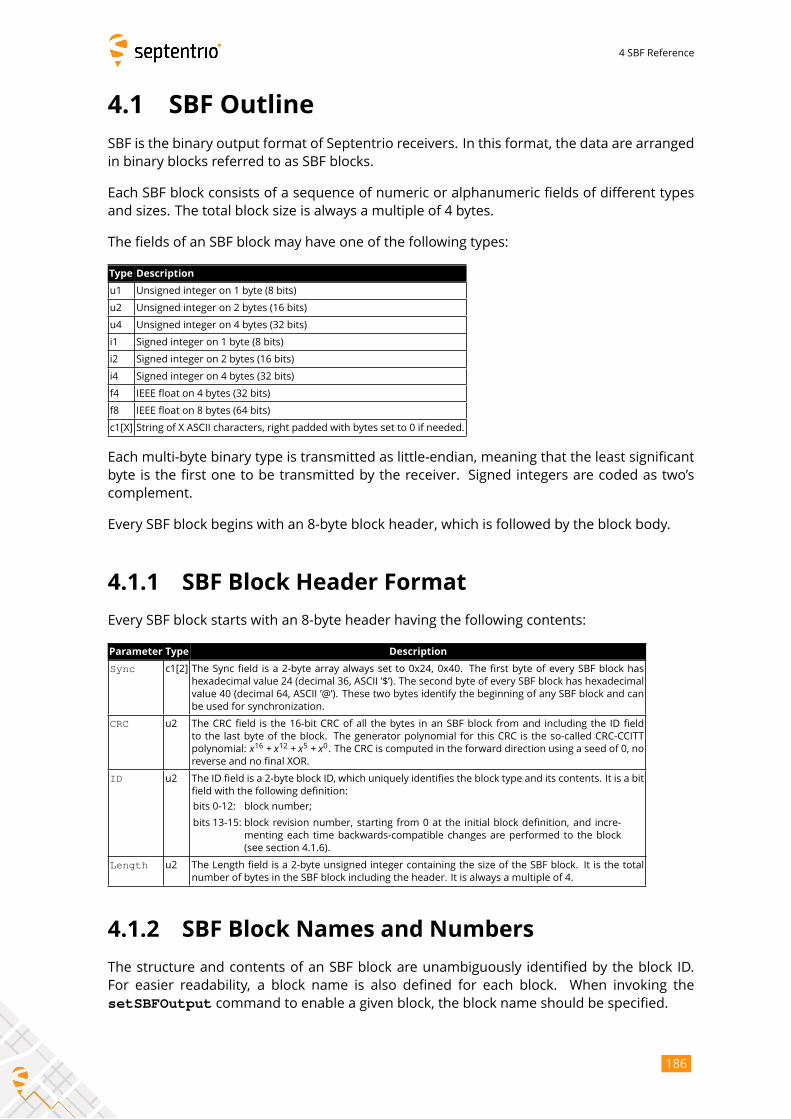
4 SBF Reference
4.1 SBF Outline
SBF is the binary output format of Septentrio receivers. In this format, the data are arranged
in binary blocks referred to as SBF blocks.
Each SBF block consists of a sequence of numeric or alphanumeric fields of different types
and sizes. The total block size is always a multiple of 4 bytes.
The fields of an SBF block may have one of the following types:
Type Description
u1 Unsigned integer on 1 byte (8 bits)
u2 Unsigned integer on 2 bytes (16 bits)
u4 Unsigned integer on 4 bytes (32 bits)
i1 Signed integer on 1 byte (8 bits)
i2 Signed integer on 2 bytes (16 bits)
i4 Signed integer on 4 bytes (32 bits)
f4 IEEE float on 4 bytes (32 bits)
f8 IEEE float on 8 bytes (64 bits)
c1[X] String of X ASCII characters, right padded with bytes set to 0 if needed.
Each multi-byte binary type is transmitted as little-endian, meaning that the least significant
byte is the first one to be transmitted by the receiver. Signed integers are coded as two’s
complement.
Every SBF block begins with an 8-byte block header, which is followed by the block body.
4.1.1 SBF Block Header Format
Every SBF block starts with an 8-byte header having the following contents:
Parameter Type Description
Sync c1[2] The Sync field is a 2-byte array always set to 0x24, 0x40. The first byte of every SBF block has
hexadecimal value 24 (decimal 36, ASCII ’$’). The second byte of every SBF block has hexadecimal
value 40 (decimal 64, ASCII ’@’). These two bytes identify the beginning of any SBF block and can
be used for synchronization.
CRC u2 The CRC field is the 16-bit CRC of all the bytes in an SBF block from and including the ID field
to the last byte of the block. The generator polynomial for this CRC is the so-called CRC-CCITT
polynomial: x16 + x12 + x5 + x0. The CRC is computed in the forward direction using a seed of 0, noreverse and no final XOR.
ID u2 The ID field is a 2-byte block ID, which uniquely identifies the block type and its contents. It is a bit
field with the following definition:
bits 0-12: block number;
bits 13-15: block revision number, starting from 0 at the initial block definition, and incre-
menting each time backwards-compatible changes are performed to the block
(see section 4.1.6).
Length u2 The Length field is a 2-byte unsigned integer containing the size of the SBF block. It is the total
number of bytes in the SBF block including the header. It is always a multiple of 4.
4.1.2 SBF Block Names and Numbers
The structure and contents of an SBF block are unambiguously identified by the block ID.
For easier readability, a block name is also defined for each block. When invoking the
setSBFOutput command to enable a given block, the block name should be specified.
186
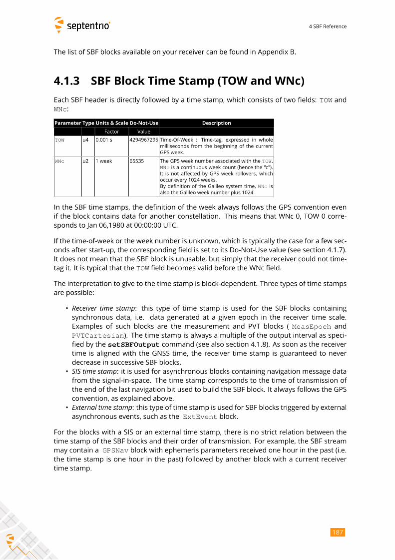
4 SBF Reference
The list of SBF blocks available on your receiver can be found in Appendix B.
4.1.3 SBF Block Time Stamp (TOW and WNc)
Each SBF header is directly followed by a time stamp, which consists of two fields: TOW andWNc:
Parameter Type Units & Scale Do-Not-Use Description
Factor Value
TOW u4 0.001 s 4294967295 Time-Of-Week : Time-tag, expressed in whole
milliseconds from the beginning of the current
GPS week.
WNc u2 1 week 65535 The GPS week number associated with the TOW.WNc is a continuous week count (hence the "c").It is not affected by GPS week rollovers, which
occur every 1024 weeks.
By definition of the Galileo system time, WNc isalso the Galileo week number plus 1024.
In the SBF time stamps, the definition of the week always follows the GPS convention even
if the block contains data for another constellation. This means that WNc 0, TOW 0 corre-
sponds to Jan 06,1980 at 00:00:00 UTC.
If the time-of-week or the week number is unknown, which is typically the case for a few sec-
onds after start-up, the corresponding field is set to its Do-Not-Use value (see section 4.1.7).
It does not mean that the SBF block is unusable, but simply that the receiver could not time-
tag it. It is typical that the TOW field becomes valid before the WNc field.
The interpretation to give to the time stamp is block-dependent. Three types of time stamps
are possible:
• Receiver time stamp: this type of time stamp is used for the SBF blocks containingsynchronous data, i.e. data generated at a given epoch in the receiver time scale.
Examples of such blocks are the measurement and PVT blocks ( MeasEpoch andPVTCartesian). The time stamp is always a multiple of the output interval as speci-fied by the setSBFOutput command (see also section 4.1.8). As soon as the receivertime is aligned with the GNSS time, the receiver time stamp is guaranteed to never
decrease in successive SBF blocks.
• SIS time stamp: it is used for asynchronous blocks containing navigation message datafrom the signal-in-space. The time stamp corresponds to the time of transmission of
the end of the last navigation bit used to build the SBF block. It always follows the GPS
convention, as explained above.
• External time stamp: this type of time stamp is used for SBF blocks triggered by externalasynchronous events, such as the ExtEvent block.
For the blocks with a SIS or an external time stamp, there is no strict relation between the
time stamp of the SBF blocks and their order of transmission. For example, the SBF stream
may contain a GPSNav block with ephemeris parameters received one hour in the past (i.e.the time stamp is one hour in the past) followed by another block with a current receiver
time stamp.
187
4 SBF Reference
4.1.4 Sub-blocks
Some blocks contain sub-blocks. For example, the SatVisibility block contains NSatInfo sub-blocks, each sub-block containing data for one particular satellite. Unless thesize of the sub-blocks is mentioned explicitly in the block description, SBF blocks that contain
sub-blocks also contain a SBLength field, which indicates the size of the sub-blocks in bytes.
4.1.5 Padding Bytes
Padding bytes are foreseen at the end of most SBF blocks and sub-blocks, so that their total
size is equal to Length or SBLength respectively. The padding bytes are just placeholdersand should not be looked at by the decoding software. Their value is not defined.
4.1.6 SBF Revision Number
Each SBF block has an associated revision number. The revision number is incremented each
time a backwards-compatible change is implemented.
As described in section 4.1.1, the block number is to be found in bits 0 to 12 of the ID field,
and the revision is in bits 13 to 15 of that field.
A backwards-compatible change consists of adding one or more fields in the padding bytes,
or in the fields marked as "reserved" in the block description. Such change should be unno-
ticed by properly written decoding software that ignore the contents of padding and reserved
fields (see also section 4.1.12). Each time such change happens, the revision number is in-
cremented. The revision at which a given field has been introduced is documented in the
block description in chapter 4.2, unless that revision is 0 (see the ReceiverSetup block asan example). It is guaranteed that if a given field exists in revision N, it will also exist in all
revisions after N: no fields are withdrawn from SBF.
4.1.7 Do-Not-Use Value
It might happen that one or more pieces of data in an SBF block are not known at block
creation time. For example, when there are insufficient satellite measurements to com-
pute a position solution, the position components found in the X, Y and Z fields of the
PVTCartesian block will not be available. To indicate that a given data item is not availableor is currently not provided by the receiver, the corresponding field is set to a ’Do-Not-Use’
value that is never reached in normal operation.
When applicable, the Do-Not-Use value is mentioned in the block description. The Do-Not-
Use value refers to the raw contents of the field, without applying the scale factor. A field set
to its Do-Not-Use value should always be discarded by the decoding software.
4.1.8 Output Rate
In general, the default output rate for each SBF block is the renewal rate of the information.
For instance, the GPSNav block is output each time a new ephemeris data set is received
188
4 SBF Reference
from a given GPS satellite. The default output rates of GNSSmeasurement blocks, PVT blocks
and integrated INS/GNSS blocks depend on your permission set. These three rates can be
checked by the command getReceiverCapabilities.
The default output rate is specified for each block in chapter 4.2. To instruct the receiver
to output a given block at its default rate, the "OnChange" rate has to be specified in thesetSBFOutput command.
Some blocks can only be output at their default rate (e.g. the GPSNav block). Others canbe decimated to a user-selectable rate. A subset of blocks can also be output "once" using
the exeSBFOnce command. This can be handy to get a one-shot overview of a particular re-ceiver state. Whether a given block supports a user-selectable rate (“Flex Rate”) and whether
it belongs to the "output once" set is indicated in the SBF block list in Appendix B.
Attempting to force another rate than the default one for those blocks that do not support
“Flex Rate” has no effect: those blocks are always output at their default rate.
4.1.9 Satellite ID and GLONASS Frequency Number
Satellites are identified by the SVID (or PRN) and FreqNr fields, defined as in the table below.
This table is only valid for the currently-supported constellations and signal types
(see 4.1.10). To ensure compatibility with future SBF upgrades, decoding software must ig-
nore SBF blocks and sub-blocks of which the satellite ID field or the signal number field is
undefined in this document.
189
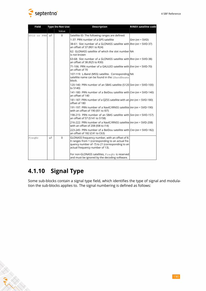
4 SBF Reference
Field Type Do-Not-Use Description RINEX satellite code
Value
SVID or PRN u1 0 Satellite ID: The following ranges are defined:
1-37: PRN number of a GPS satellite Gnn (nn = SVID)38-61: Slot number of a GLONASS satellite with
an offset of 37 (R01 to R24)
Rnn (nn = SVID-37)62: GLONASS satellite of which the slot number
is not known
NA
63-68: Slot number of a GLONASS satellite with
an offset of 38 (R25 to R30)
Rnn (nn = SVID-38)71-106: PRN number of a GALILEO satellite with
an offset of 70
Enn (nn = SVID-70)107-119: L-Band (MSS) satellite. Corresponding
satellite name can be found in the LBandBeamsblock.
NA
120-140: PRN number of an SBAS satellite (S120
to S140)
Snn (nn = SVID-100)141-180: PRN number of a BeiDou satellite with
an offset of 140
Cnn (nn = SVID-140)181-187: PRN number of a QZSS satellite with an
offset of 180
Jnn (nn = SVID-180)191-197: PRN number of a NavIC/IRNSS satellite
with an offset of 190 (I01 to I07)
Inn (nn = SVID-190)198-215: PRN number of an SBAS satellite with
an offset of 57 (S141 to S158)
Snn (nn = SVID-157)216-222: PRN number of a NavIC/IRNSS satellite
with an offset of 208 (I08 to I14)
Inn (nn = SVID-208)223-245: PRN number of a BeiDou satellite with
an offset of 182 (C41 to C63)
Cnn (nn = SVID-182)FreqNr u1 0 GLONASS frequency number, with an offset of 8.
It ranges from 1 (corresponding to an actual fre-
quency number of -7) to 21 (corresponding to an
actual frequency number of 13).
For non-GLONASS satellites, FreqNr is reservedand must be ignored by the decoding software.
4.1.10 Signal Type
Some sub-blocks contain a signal type field, which identifies the type of signal and modula-
tion the sub-blocks applies to. The signal numbering is defined as follows:
190
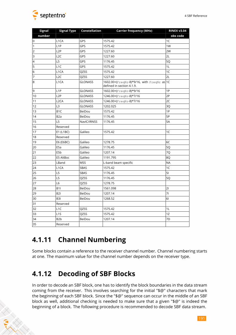
4 SBF Reference
Signal Signal Type Constellation Carrier frequency (MHz) RINEX v3.04
number obs code
0 L1CA GPS 1575.42 1C
1 L1P GPS 1575.42 1W
2 L2P GPS 1227.60 2W
3 L2C GPS 1227.60 2L
4 L5 GPS 1176.45 5Q
5 L1C GPS 1575.42 1L
6 L1CA QZSS 1575.42 1C
7 L2C QZSS 1227.60 2L
8 L1CA GLONASS 1602.00+(FreqNr-8)*9/16, with FreqNr asdefined in section 4.1.9.
1C
9 L1P GLONASS 1602.00+(FreqNr-8)*9/16 1P
10 L2P GLONASS 1246.00+(FreqNr-8)*7/16 2P
11 L2CA GLONASS 1246.00+(FreqNr-8)*7/16 2C
12 L3 GLONASS 1202.025 3Q
13 B1C BeiDou 1575.42 1P
14 B2a BeiDou 1176.45 5P
15 L5 NavIC/IRNSS 1176.45 5A
16 Reserved
17 E1 (L1BC) Galileo 1575.42 1C
18 Reserved
19 E6 (E6BC) Galileo 1278.75 6C
20 E5a Galileo 1176.45 5Q
21 E5b Galileo 1207.14 7Q
22 E5 AltBoc Galileo 1191.795 8Q
23 LBand MSS L-band beam specific NA
24 L1CA SBAS 1575.42 1C
25 L5 SBAS 1176.45 5I
26 L5 QZSS 1176.45 5Q
27 L6 QZSS 1278.75
28 B1I BeiDou 1561.098 2I
29 B2I BeiDou 1207.14 7I
30 B3I BeiDou 1268.52 6I
31 Reserved
32 L1C QZSS 1575.42 1L
33 L1S QZSS 1575.42 1Z
34 B2b BeiDou 1207.14 7D
35 Reserved
4.1.11 Channel Numbering
Some blocks contain a reference to the receiver channel number. Channel numbering starts
at one. The maximum value for the channel number depends on the receiver type.
4.1.12 Decoding of SBF Blocks
In order to decode an SBF block, one has to identify the block boundaries in the data stream
coming from the receiver. This involves searching for the initial "$@" characters that mark
the beginning of each SBF block. Since the "$@" sequence can occur in the middle of an SBF
block as well, additional checking is needed to make sure that a given "$@" is indeed the
beginning of a block. The following procedure is recommended to decode SBF data stream.
191
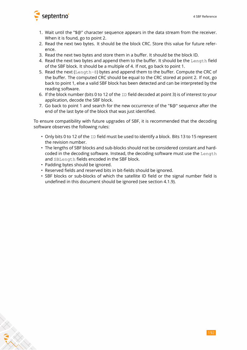
4 SBF Reference
1. Wait until the "$@" character sequence appears in the data stream from the receiver.
When it is found, go to point 2.
2. Read the next two bytes. It should be the block CRC. Store this value for future refer-
ence.
3. Read the next two bytes and store them in a buffer. It should be the block ID.
4. Read the next two bytes and append them to the buffer. It should be the Length fieldof the SBF block. It should be a multiple of 4. If not, go back to point 1.
5. Read the next (Length-8) bytes and append them to the buffer. Compute the CRC ofthe buffer. The computed CRC should be equal to the CRC stored at point 2. If not, go
back to point 1, else a valid SBF block has been detected and can be interpreted by the
reading software.
6. If the block number (bits 0 to 12 of the ID field decoded at point 3) is of interest to yourapplication, decode the SBF block.
7. Go back to point 1 and search for the new occurrence of the "$@" sequence after the
end of the last byte of the block that was just identified.
To ensure compatibility with future upgrades of SBF, it is recommended that the decoding
software observes the following rules:
• Only bits 0 to 12 of the ID field must be used to identify a block. Bits 13 to 15 representthe revision number.
• The lengths of SBF blocks and sub-blocks should not be considered constant and hard-
coded in the decoding software. Instead, the decoding software must use the Lengthand SBLength fields encoded in the SBF block.
• Padding bytes should be ignored.
• Reserved fields and reserved bits in bit-fields should be ignored.
• SBF blocks or sub-blocks of which the satellite ID field or the signal number field is
undefined in this document should be ignored (see section 4.1.9).
192
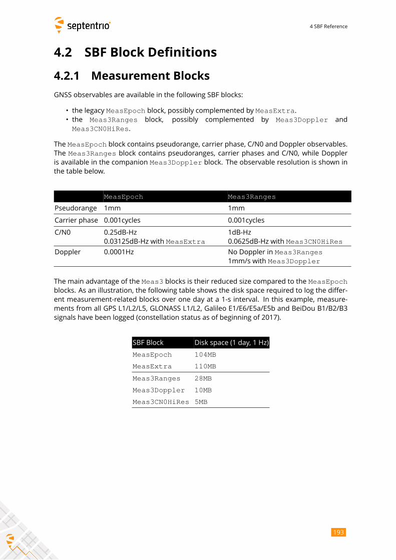
4 SBF Reference
4.2 SBF Block Definitions
4.2.1 Measurement Blocks
GNSS observables are available in the following SBF blocks:
• the legacy MeasEpoch block, possibly complemented by MeasExtra.• the Meas3Ranges block, possibly complemented by Meas3Doppler and
Meas3CN0HiRes.
The MeasEpoch block contains pseudorange, carrier phase, C/N0 and Doppler observables.The Meas3Ranges block contains pseudoranges, carrier phases and C/N0, while Doppleris available in the companion Meas3Doppler block. The observable resolution is shown inthe table below.
MeasEpoch Meas3Ranges
Pseudorange 1mm 1mm
Carrier phase 0.001cycles 0.001cycles
C/N0 0.25dB-Hz
0.03125dB-Hz with MeasExtra1dB-Hz
0.0625dB-Hz with Meas3CN0HiRes
Doppler 0.0001Hz No Doppler in Meas3Ranges1mm/s with Meas3Doppler
The main advantage of the Meas3 blocks is their reduced size compared to the MeasEpochblocks. As an illustration, the following table shows the disk space required to log the differ-
ent measurement-related blocks over one day at a 1-s interval. In this example, measure-
ments from all GPS L1/L2/L5, GLONASS L1/L2, Galileo E1/E6/E5a/E5b and BeiDou B1/B2/B3
signals have been logged (constellation status as of beginning of 2017).
SBF Block Disk space (1 day, 1 Hz)
MeasEpoch 104MB
MeasExtra 110MB
Meas3Ranges 28MB
Meas3Doppler 10MB
Meas3CN0HiRes 5MB
193
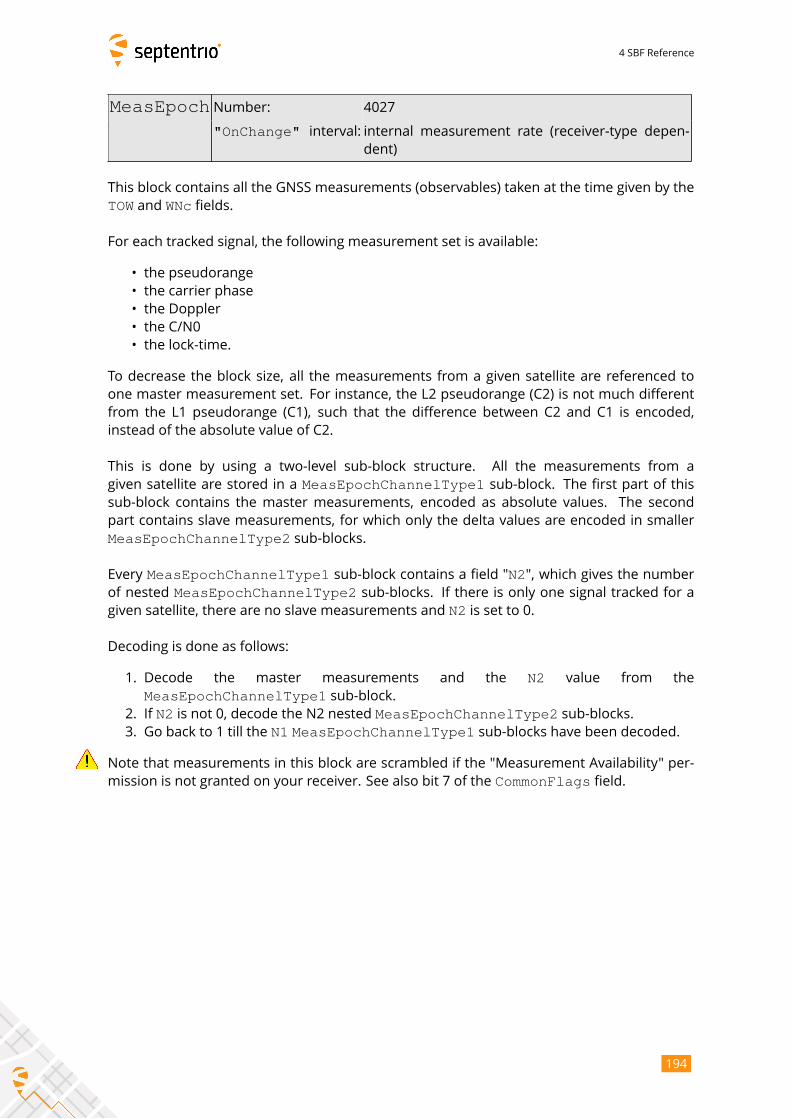
4 SBF Reference
MeasEpoch Number: 4027
"OnChange" interval: internal measurement rate (receiver-type depen-dent)
This block contains all the GNSS measurements (observables) taken at the time given by the
TOW and WNc fields.
For each tracked signal, the following measurement set is available:
• the pseudorange
• the carrier phase
• the Doppler
• the C/N0
• the lock-time.
To decrease the block size, all the measurements from a given satellite are referenced to
one master measurement set. For instance, the L2 pseudorange (C2) is not much different
from the L1 pseudorange (C1), such that the difference between C2 and C1 is encoded,
instead of the absolute value of C2.
This is done by using a two-level sub-block structure. All the measurements from a
given satellite are stored in a MeasEpochChannelType1 sub-block. The first part of thissub-block contains the master measurements, encoded as absolute values. The second
part contains slave measurements, for which only the delta values are encoded in smaller
MeasEpochChannelType2 sub-blocks.
Every MeasEpochChannelType1 sub-block contains a field "N2", which gives the numberof nested MeasEpochChannelType2 sub-blocks. If there is only one signal tracked for agiven satellite, there are no slave measurements and N2 is set to 0.
Decoding is done as follows:
1. Decode the master measurements and the N2 value from the
MeasEpochChannelType1 sub-block.2. If N2 is not 0, decode the N2 nested MeasEpochChannelType2 sub-blocks.3. Go back to 1 till the N1 MeasEpochChannelType1 sub-blocks have been decoded.
Note that measurements in this block are scrambled if the "Measurement Availability" per-
mission is not granted on your receiver. See also bit 7 of the CommonFlags field.
194
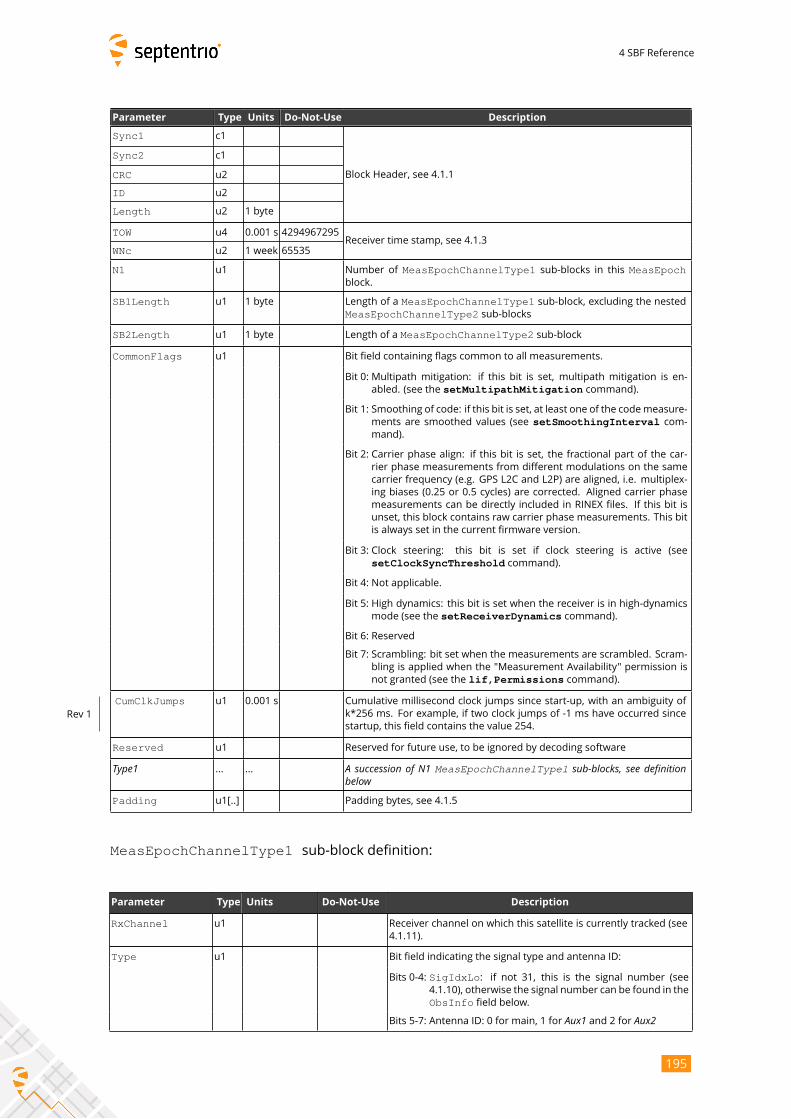
4 SBF Reference
Parameter Type Units Do-Not-Use Description
Sync1 c1
Block Header, see 4.1.1
Sync2 c1
CRC u2
ID u2
Length u2 1 byte
TOW u4 0.001 s 4294967295Receiver time stamp, see 4.1.3
WNc u2 1 week 65535
N1 u1 Number of MeasEpochChannelType1 sub-blocks in this MeasEpochblock.
SB1Length u1 1 byte Length of a MeasEpochChannelType1 sub-block, excluding the nestedMeasEpochChannelType2 sub-blocks
SB2Length u1 1 byte Length of a MeasEpochChannelType2 sub-block
CommonFlags u1 Bit field containing flags common to all measurements.
Bit 0: Multipath mitigation: if this bit is set, multipath mitigation is en-
abled. (see the setMultipathMitigation command).
Bit 1: Smoothing of code: if this bit is set, at least one of the codemeasure-
ments are smoothed values (see setSmoothingInterval com-mand).
Bit 2: Carrier phase align: if this bit is set, the fractional part of the car-
rier phase measurements from different modulations on the same
carrier frequency (e.g. GPS L2C and L2P) are aligned, i.e. multiplex-
ing biases (0.25 or 0.5 cycles) are corrected. Aligned carrier phase
measurements can be directly included in RINEX files. If this bit is
unset, this block contains raw carrier phase measurements. This bit
is always set in the current firmware version.
Bit 3: Clock steering: this bit is set if clock steering is active (see
setClockSyncThreshold command).
Bit 4: Not applicable.
Bit 5: High dynamics: this bit is set when the receiver is in high-dynamics
mode (see the setReceiverDynamics command).
Bit 6: Reserved
Bit 7: Scrambling: bit set when the measurements are scrambled. Scram-
bling is applied when the "Measurement Availability" permission is
not granted (see the lif,Permissions command).
CumClkJumps u1 0.001 s Cumulative millisecond clock jumps since start-up, with an ambiguity of
k*256 ms. For example, if two clock jumps of -1 ms have occurred since
startup, this field contains the value 254.
Rev 1
Reserved u1 Reserved for future use, to be ignored by decoding software
Type1 ... ... A succession of N1 MeasEpochChannelType1 sub-blocks, see definitionbelowPadding u1[..] Padding bytes, see 4.1.5
MeasEpochChannelType1 sub-block definition:
Parameter Type Units Do-Not-Use Description
RxChannel u1 Receiver channel on which this satellite is currently tracked (see
4.1.11).
Type u1 Bit field indicating the signal type and antenna ID:
Bits 0-4: SigIdxLo: if not 31, this is the signal number (see4.1.10), otherwise the signal number can be found in the
ObsInfo field below.
Bits 5-7: Antenna ID: 0 for main, 1 for Aux1 and 2 for Aux2
195
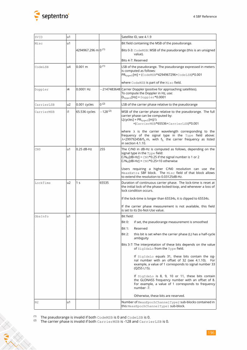
4 SBF Reference
SVID u1 Satellite ID, see 4.1.9
Misc u1 Bit field containing the MSB of the pseudorange.
4294967.296 m 0(1)
Bits 0-3: CodeMSB: MSB of the pseudorange (this is an unsignedvalue).
Bits 4-7: Reserved
CodeLSB u4 0.001 m 0(1)
LSB of the pseudorange. The pseudorange expressed in meters
is computed as follows:
PRtype1[m] = (CodeMSB*4294967296+CodeLSB)*0.001
where CodeMSB is part of the Misc field.
Doppler i4 0.0001 Hz −2147483648 Carrier Doppler (positive for approaching satellites).To compute the Doppler in Hz, use:
Dtype1[Hz] = Doppler*0.0001
CarrierLSB u2 0.001 cycles 0(2)
LSB of the carrier phase relative to the pseudorange
CarrierMSB i1 65.536 cycles −128 (2) MSB of the carrier phase relative to the pseudorange. The full
carrier phase can be computed by:
L[cycles] = PRtype1[m]/λ+(CarrierMSB*65536+CarrierLSB)*0.001
where λ is the carrier wavelength corresponding to the
frequency of the signal type in the Type field above:
λ=299792458/fLm, with fL the carrier frequency as listed
in section 4.1.10.
CN0 u1 0.25 dB-Hz 255 The C/N0 in dB-Hz is computed as follows, depending on the
signal type in the Type field:C/N0[dB-Hz] = CN0*0.25 if the signal number is 1 or 2C/N0[dB-Hz] = CN0*0.25+10 otherwise
Users requiring a higher C/N0 resolution can use the
MeasExtra SBF block. The Misc field of that block allows
to extend the resolution to 0.03125dB-Hz.
LockTime u2 1 s 65535 Duration of continuous carrier phase. The lock-time is reset at
the initial lock of the phase-locked-loop, and whenever a loss of
lock condition occurs.
If the lock-time is longer than 65534s, it is clipped to 65534s.
If the carrier phase measurement is not available, this field
is set to its Do-Not-Use value.
ObsInfo u1 Bit field:
Bit 0: if set, the pseudorange measurement is smoothed
Bit 1: Reserved
Bit 2: this bit is set when the carrier phase (L) has a half-cycle
ambiguity
Bits 3-7: The interpretation of these bits depends on the value
of SigIdxLo from the Type field.
If SigIdxLo equals 31, these bits contain the sig-nal number with an offset of 32 (see 4.1.10). For
example, a value of 1 corresponds to signal number 33
(QZSS L1S).
If SigIdxLo is 8, 9, 10 or 11, these bits containthe GLONASS frequency number with an offset of 8.
For example, a value of 1 corresponds to frequency
number -7.
Otherwise, these bits are reserved.
N2 u1 Number of MeasEpochChannelType2 sub-blocks contained inthis MeasEpochChannelType1 sub-block.
(1)The pseudorange is invalid if both CodeMSB is 0 and CodeLSB is 0.
(2)The carrier phase is invalid if both CarrierMSB is -128 and CarrierLSB is 0.
196
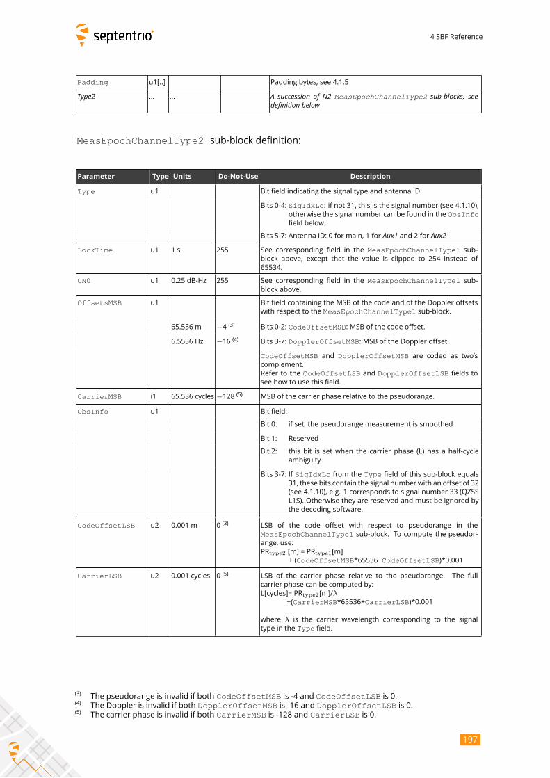
4 SBF Reference
Padding u1[..] Padding bytes, see 4.1.5
Type2 ... ... A succession of N2 MeasEpochChannelType2 sub-blocks, seedefinition below
MeasEpochChannelType2 sub-block definition:
Parameter Type Units Do-Not-Use Description
Type u1 Bit field indicating the signal type and antenna ID:
Bits 0-4: SigIdxLo: if not 31, this is the signal number (see 4.1.10),otherwise the signal number can be found in the ObsInfofield below.
Bits 5-7: Antenna ID: 0 for main, 1 for Aux1 and 2 for Aux2LockTime u1 1 s 255 See corresponding field in the MeasEpochChannelType1 sub-
block above, except that the value is clipped to 254 instead of
65534.
CN0 u1 0.25 dB-Hz 255 See corresponding field in the MeasEpochChannelType1 sub-block above.
OffsetsMSB u1 Bit field containing the MSB of the code and of the Doppler offsets
with respect to the MeasEpochChannelType1 sub-block.
65.536 m −4 (3) Bits 0-2: CodeOffsetMSB: MSB of the code offset.
6.5536 Hz −16 (4) Bits 3-7: DopplerOffsetMSB: MSB of the Doppler offset.
CodeOffsetMSB and DopplerOffsetMSB are coded as two’scomplement.
Refer to the CodeOffsetLSB and DopplerOffsetLSB fields to
see how to use this field.
CarrierMSB i1 65.536 cycles −128 (5) MSB of the carrier phase relative to the pseudorange.
ObsInfo u1 Bit field:
Bit 0: if set, the pseudorange measurement is smoothed
Bit 1: Reserved
Bit 2: this bit is set when the carrier phase (L) has a half-cycle
ambiguity
Bits 3-7: If SigIdxLo from the Type field of this sub-block equals
31, these bits contain the signal number with an offset of 32
(see 4.1.10), e.g. 1 corresponds to signal number 33 (QZSS
L1S). Otherwise they are reserved and must be ignored by
the decoding software.
CodeOffsetLSB u2 0.001 m 0(3)
LSB of the code offset with respect to pseudorange in the
MeasEpochChannelType1 sub-block. To compute the pseudor-ange, use:
PRtype2 [m] = PRtype1[m]
+ (CodeOffsetMSB*65536+CodeOffsetLSB)*0.001
CarrierLSB u2 0.001 cycles 0(5)
LSB of the carrier phase relative to the pseudorange. The full
carrier phase can be computed by:
L[cycles]= PRtype2[m]/λ+(CarrierMSB*65536+CarrierLSB)*0.001
where λ is the carrier wavelength corresponding to the signaltype in the Type field.
(3)The pseudorange is invalid if both CodeOffsetMSB is -4 and CodeOffsetLSB is 0.
(4)The Doppler is invalid if both DopplerOffsetMSB is -16 and DopplerOffsetLSB is 0.
(5)The carrier phase is invalid if both CarrierMSB is -128 and CarrierLSB is 0.
197
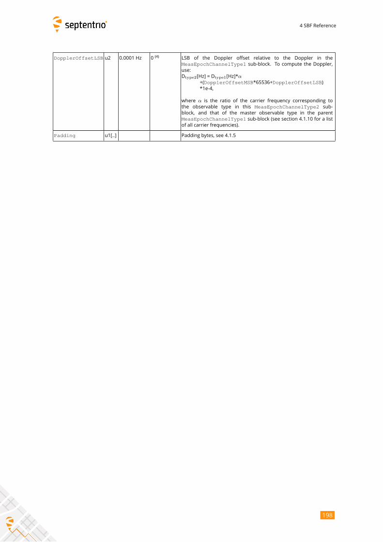
4 SBF Reference
DopplerOffsetLSB u2 0.0001 Hz 0(4)
LSB of the Doppler offset relative to the Doppler in the
MeasEpochChannelType1 sub-block. To compute the Doppler,use:
Dtype2[Hz] = Dtype1[Hz]*α+(DopplerOffsetMSB*65536+DopplerOffsetLSB)*1e-4,
where α is the ratio of the carrier frequency corresponding tothe observable type in this MeasEpochChannelType2 sub-
block, and that of the master observable type in the parent
MeasEpochChannelType1 sub-block (see section 4.1.10 for a listof all carrier frequencies).
Padding u1[..] Padding bytes, see 4.1.5
198
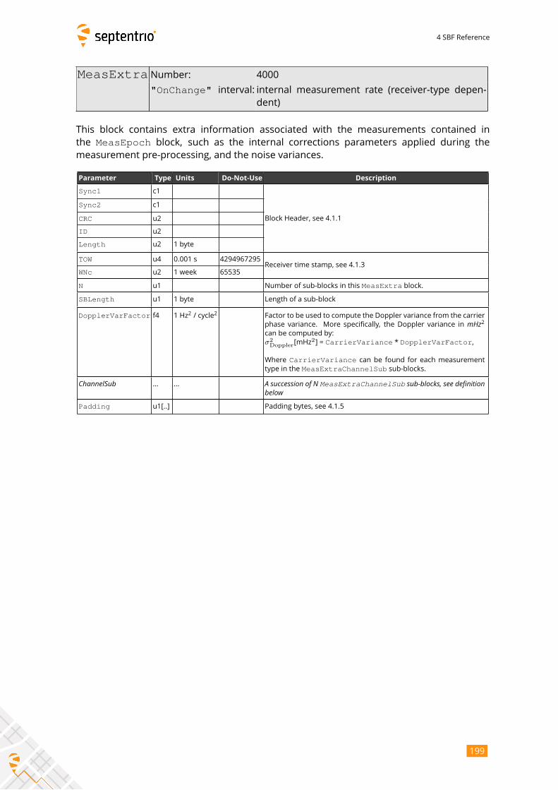
4 SBF Reference
MeasExtra Number: 4000
"OnChange" interval: internal measurement rate (receiver-type depen-dent)
This block contains extra information associated with the measurements contained in
the MeasEpoch block, such as the internal corrections parameters applied during themeasurement pre-processing, and the noise variances.
Parameter Type Units Do-Not-Use Description
Sync1 c1
Block Header, see 4.1.1
Sync2 c1
CRC u2
ID u2
Length u2 1 byte
TOW u4 0.001 s 4294967295Receiver time stamp, see 4.1.3
WNc u2 1 week 65535
N u1 Number of sub-blocks in this MeasExtra block.
SBLength u1 1 byte Length of a sub-block
DopplerVarFactor f4 1 Hz2/ cycle
2Factor to be used to compute the Doppler variance from the carrier
phase variance. More specifically, the Doppler variance in mHz2can be computed by:
σ2Doppler[mHz
2] = CarrierVariance * DopplerVarFactor,
Where CarrierVariance can be found for each measurementtype in the MeasExtraChannelSub sub-blocks.
ChannelSub ... ... A succession of N MeasExtraChannelSub sub-blocks, see definitionbelowPadding u1[..] Padding bytes, see 4.1.5
199
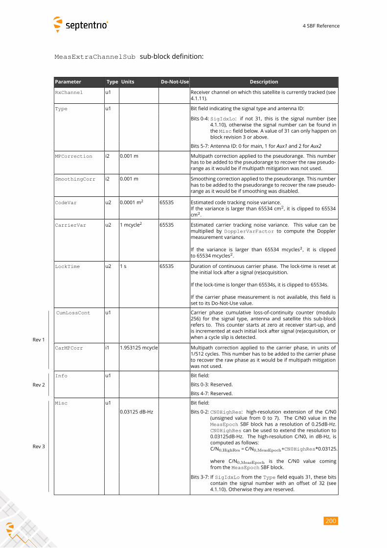
4 SBF Reference
MeasExtraChannelSub sub-block definition:
Parameter Type Units Do-Not-Use Description
RxChannel u1 Receiver channel on which this satellite is currently tracked (see
4.1.11).
Type u1 Bit field indicating the signal type and antenna ID:
Bits 0-4: SigIdxLo: if not 31, this is the signal number (see4.1.10), otherwise the signal number can be found in
the Misc field below. A value of 31 can only happen onblock revision 3 or above.
Bits 5-7: Antenna ID: 0 for main, 1 for Aux1 and 2 for Aux2MPCorrection i2 0.001 m Multipath correction applied to the pseudorange. This number
has to be added to the pseudorange to recover the raw pseudo-
range as it would be if multipath mitigation was not used.
SmoothingCorr i2 0.001 m Smoothing correction applied to the pseudorange. This number
has to be added to the pseudorange to recover the raw pseudo-
range as it would be if smoothing was disabled.
CodeVar u2 0.0001 m2
65535 Estimated code tracking noise variance.
If the variance is larger than 65534 cm2, it is clipped to 65534
cm2.
CarrierVar u2 1 mcycle2
65535 Estimated carrier tracking noise variance. This value can be
multiplied by DopplerVarFactor to compute the Dopplermeasurement variance.
If the variance is larger than 65534 mcycles2, it is clipped
to 65534 mcycles2.
LockTime u2 1 s 65535 Duration of continuous carrier phase. The lock-time is reset at
the initial lock after a signal (re)acquisition.
If the lock-time is longer than 65534s, it is clipped to 65534s.
If the carrier phase measurement is not available, this field is
set to its Do-Not-Use value.
CumLossCont u1 Carrier phase cumulative loss-of-continuity counter (modulo
256) for the signal type, antenna and satellite this sub-block
refers to. This counter starts at zero at receiver start-up, and
is incremented at each initial lock after signal (re)acquisition, or
when a cycle slip is detected.
CarMPCorr i1 1.953125 mcycle Multipath correction applied to the carrier phase, in units of
1/512 cycles. This number has to be added to the carrier phase
to recover the raw phase as it would be if multipath mitigation
was not used.
Rev 1
Info u1 Bit field:
Bits 0-3: Reserved.
Bits 4-7: Reserved.
Rev 2
Misc u1 Bit field:
0.03125 dB-Hz Bits 0-2: CN0HighRes: high-resolution extension of the C/N0(unsigned value from 0 to 7). The C/N0 value in the
MeasEpoch SBF block has a resolution of 0.25dB-Hz.CN0HighRes can be used to extend the resolution to0.03125dB-Hz. The high-resolution C/N0, in dB-Hz, is
computed as follows:
C/N0,HighRes = C/N0,MeasEpoch+CN0HighRes*0.03125.
where C/N0,MeasEpoch is the C/N0 value coming
from the MeasEpoch SBF block.
Bits 3-7: If SigIdxLo from the Type field equals 31, these bits
contain the signal number with an offset of 32 (see
4.1.10). Otherwise they are reserved.
Rev 3
200

4 SBF Reference
Padding u1[..] Padding bytes, see 4.1.5
201
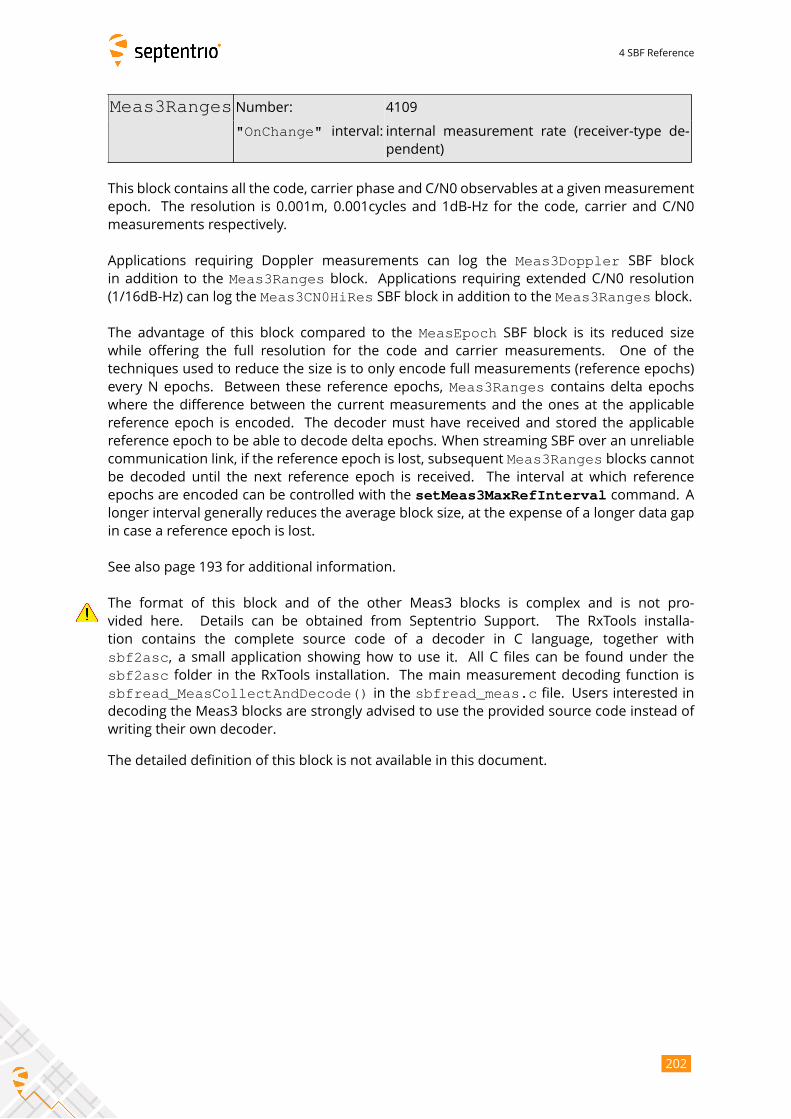
4 SBF Reference
Meas3Ranges Number: 4109
"OnChange" interval: internal measurement rate (receiver-type de-pendent)
This block contains all the code, carrier phase and C/N0 observables at a givenmeasurement
epoch. The resolution is 0.001m, 0.001cycles and 1dB-Hz for the code, carrier and C/N0
measurements respectively.
Applications requiring Doppler measurements can log the Meas3Doppler SBF blockin addition to the Meas3Ranges block. Applications requiring extended C/N0 resolution(1/16dB-Hz) can log the Meas3CN0HiRes SBF block in addition to the Meas3Ranges block.
The advantage of this block compared to the MeasEpoch SBF block is its reduced sizewhile offering the full resolution for the code and carrier measurements. One of the
techniques used to reduce the size is to only encode full measurements (reference epochs)
every N epochs. Between these reference epochs, Meas3Ranges contains delta epochswhere the difference between the current measurements and the ones at the applicable
reference epoch is encoded. The decoder must have received and stored the applicable
reference epoch to be able to decode delta epochs. When streaming SBF over an unreliable
communication link, if the reference epoch is lost, subsequent Meas3Ranges blocks cannotbe decoded until the next reference epoch is received. The interval at which reference
epochs are encoded can be controlled with the setMeas3MaxRefInterval command. Alonger interval generally reduces the average block size, at the expense of a longer data gap
in case a reference epoch is lost.
See also page 193 for additional information.
The format of this block and of the other Meas3 blocks is complex and is not pro-
vided here. Details can be obtained from Septentrio Support. The RxTools installa-
tion contains the complete source code of a decoder in C language, together with
sbf2asc, a small application showing how to use it. All C files can be found under the
sbf2asc folder in the RxTools installation. The main measurement decoding function issbfread_MeasCollectAndDecode() in the sbfread_meas.c file. Users interested in
decoding the Meas3 blocks are strongly advised to use the provided source code instead of
writing their own decoder.
The detailed definition of this block is not available in this document.
202

4 SBF Reference
Meas3CN0HiRes Number: 4110
"OnChange" interval: internal measurement rate (receiver-typedependent)
The Meas3CN0HiRes block is an extension of the Meas3Ranges block containing thefractional part of the C/N0 values. The resolution of the C/N0 value in the Meas3RangesSBF block is 1dB-Hz. Applications requiring a finer C/N0 resolution (0.0625dB-Hz) must log
the Meas3CN0HiRes block together with the Meas3Ranges block.
The detailed definition of this block is not available in this document.
203

4 SBF Reference
Meas3Doppler Number: 4111
"OnChange" interval: internal measurement rate (receiver-type de-pendent)
The Meas3Doppler block is an extension of the Meas3Ranges block containing therange-rate (Doppler) values. Applications requiring range-rate or Doppler observables must
log the Meas3Doppler block together with the Meas3Ranges block.
The detailed definition of this block is not available in this document.
204
4 SBF Reference
Meas3PP Number: 4112
"OnChange" interval: internal measurement rate (receiver-type dependent)
The Meas3PP block is an extension of the Meas3Ranges block containing various
Septentrio-proprietary flags and values needed for accurate post-processing or re-
processing of the PVT from the measurements in the Meas3Ranges SBF block. This blockmust be logged together with Meas3Ranges.
The detailed definition of this block is not available in this document.
205
4 SBF Reference
Meas3MP Number: 4113
"OnChange" interval: internal measurement rate (receiver-type dependent)
The Meas3MP block is an extension of the Meas3Ranges block containing the multipathcorrection applied by the receiver. It can be used for research purposes to undo the receiver
multipath mitigation and revert to unmitigated data. This block must be logged together
with Meas3Ranges.
The detailed definition of this block is not available in this document.
206
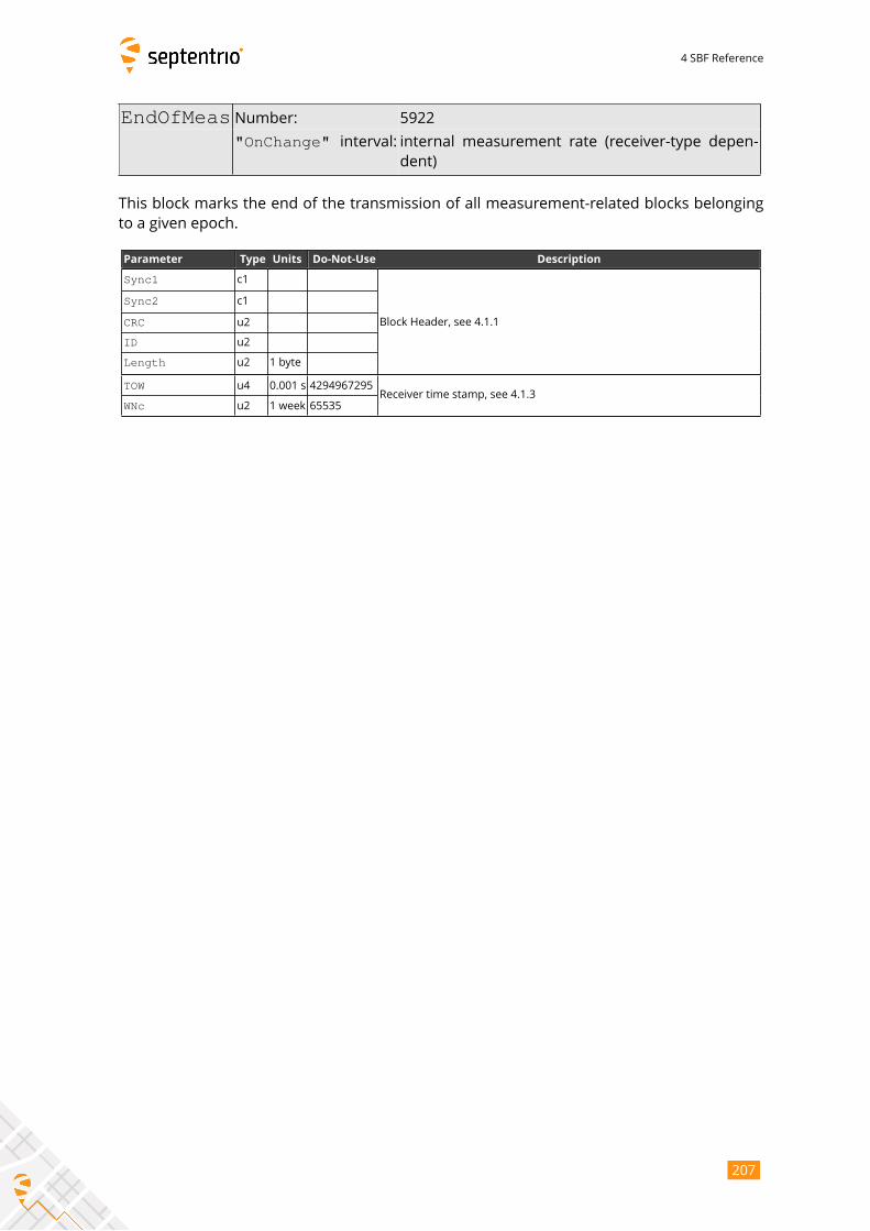
4 SBF Reference
EndOfMeas Number: 5922
"OnChange" interval: internal measurement rate (receiver-type depen-dent)
This block marks the end of the transmission of all measurement-related blocks belonging
to a given epoch.
Parameter Type Units Do-Not-Use Description
Sync1 c1
Block Header, see 4.1.1
Sync2 c1
CRC u2
ID u2
Length u2 1 byte
TOW u4 0.001 s 4294967295Receiver time stamp, see 4.1.3
WNc u2 1 week 65535
207
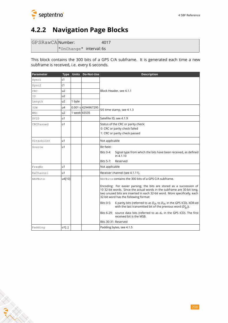
4 SBF Reference
4.2.2 Navigation Page Blocks
GPSRawCA Number: 4017
"OnChange" interval: 6s
This block contains the 300 bits of a GPS C/A subframe. It is generated each time a new
subframe is received, i.e. every 6 seconds.
Parameter Type Units Do-Not-Use Description
Sync1 c1
Block Header, see 4.1.1
Sync2 c1
CRC u2
ID u2
Length u2 1 byte
TOW u4 0.001 s 4294967295SIS time stamp, see 4.1.3
WNc u2 1 week 65535
SVID u1 Satellite ID, see 4.1.9
CRCPassed u1 Status of the CRC or parity check:
0: CRC or parity check failed
1: CRC or parity check passed
ViterbiCnt u1 Not applicable
Source u1 Bit field:
Bits 0-4: Signal type from which the bits have been received, as defined
in 4.1.10
Bits 5-7: Reserved
FreqNr u1 Not applicable
RxChannel u1 Receiver channel (see 4.1.11).
NAVBits u4[10] NAVBits contains the 300 bits of a GPS C/A subframe.
Encoding: For easier parsing, the bits are stored as a succession of
10 32-bit words. Since the actual words in the subframe are 30-bit long,
two unused bits are inserted in each 32-bit word. More specifically, each
32-bit word has the following format:
Bits 0-5: 6 parity bits (referred to as D25 to D30 in the GPS ICD), XOR-edwith the last transmitted bit of the previous word (D∗
30)).
Bits 6-29: source data bits (referred to as dn in the GPS ICD). The firstreceived bit is the MSB.
Bits 30-31: Reserved
Padding u1[..] Padding bytes, see 4.1.5
208
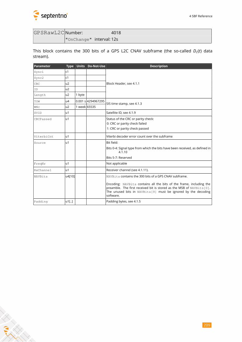
4 SBF Reference
GPSRawL2C Number: 4018
"OnChange" interval: 12s
This block contains the 300 bits of a GPS L2C CNAV subframe (the so-called Dc(t) datastream).
Parameter Type Units Do-Not-Use Description
Sync1 c1
Block Header, see 4.1.1
Sync2 c1
CRC u2
ID u2
Length u2 1 byte
TOW u4 0.001 s 4294967295SIS time stamp, see 4.1.3
WNc u2 1 week 65535
SVID u1 Satellite ID, see 4.1.9
CRCPassed u1 Status of the CRC or parity check:
0: CRC or parity check failed
1: CRC or parity check passed
ViterbiCnt u1 Viterbi decoder error count over the subframe
Source u1 Bit field:
Bits 0-4: Signal type from which the bits have been received, as defined in
4.1.10
Bits 5-7: Reserved
FreqNr u1 Not applicable
RxChannel u1 Receiver channel (see 4.1.11).
NAVBits u4[10] NAVBits contains the 300 bits of a GPS CNAV subframe.
Encoding: NAVBits contains all the bits of the frame, including thepreamble. The first received bit is stored as the MSB of NAVBits[0].The unused bits in NAVBits[9] must be ignored by the decodingsoftware.
Padding u1[..] Padding bytes, see 4.1.5
209
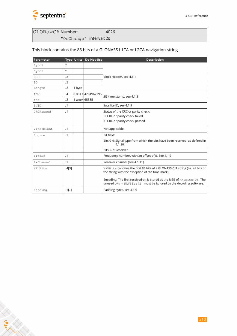
4 SBF Reference
GLORawCA Number: 4026
"OnChange" interval: 2s
This block contains the 85 bits of a GLONASS L1CA or L2CA navigation string.
Parameter Type Units Do-Not-Use Description
Sync1 c1
Block Header, see 4.1.1
Sync2 c1
CRC u2
ID u2
Length u2 1 byte
TOW u4 0.001 s 4294967295SIS time stamp, see 4.1.3
WNc u2 1 week 65535
SVID u1 Satellite ID, see 4.1.9
CRCPassed u1 Status of the CRC or parity check:
0: CRC or parity check failed
1: CRC or parity check passed
ViterbiCnt u1 Not applicable
Source u1 Bit field:
Bits 0-4: Signal type from which the bits have been received, as defined in
4.1.10
Bits 5-7: Reserved
FreqNr u1 Frequency number, with an offset of 8. See 4.1.9
RxChannel u1 Receiver channel (see 4.1.11).
NAVBits u4[3] NAVBits contains the first 85 bits of a GLONASS C/A string (i.e. all bits ofthe string with the exception of the time mark).
Encoding: The first received bit is stored as the MSB of NAVBits[0]. Theunused bits in NAVBits[2]must be ignored by the decoding software.
Padding u1[..] Padding bytes, see 4.1.5
210
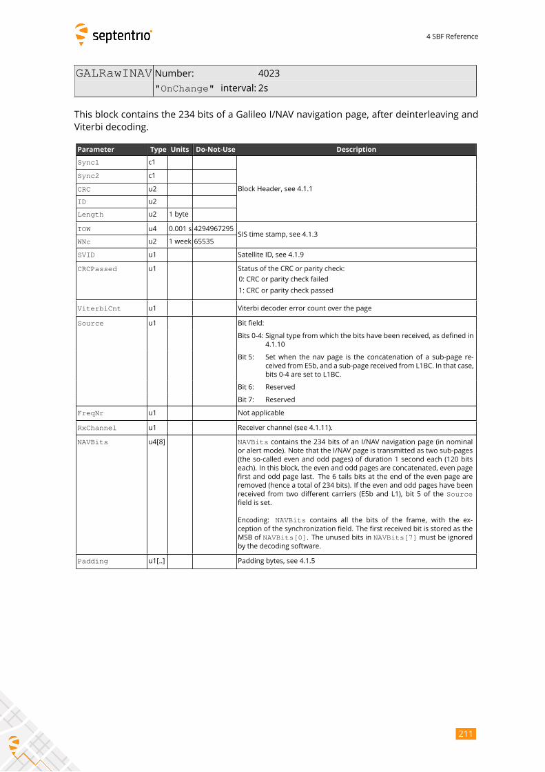
4 SBF Reference
GALRawINAV Number: 4023
"OnChange" interval: 2s
This block contains the 234 bits of a Galileo I/NAV navigation page, after deinterleaving and
Viterbi decoding.
Parameter Type Units Do-Not-Use Description
Sync1 c1
Block Header, see 4.1.1
Sync2 c1
CRC u2
ID u2
Length u2 1 byte
TOW u4 0.001 s 4294967295SIS time stamp, see 4.1.3
WNc u2 1 week 65535
SVID u1 Satellite ID, see 4.1.9
CRCPassed u1 Status of the CRC or parity check:
0: CRC or parity check failed
1: CRC or parity check passed
ViterbiCnt u1 Viterbi decoder error count over the page
Source u1 Bit field:
Bits 0-4: Signal type from which the bits have been received, as defined in
4.1.10
Bit 5: Set when the nav page is the concatenation of a sub-page re-
ceived from E5b, and a sub-page received from L1BC. In that case,
bits 0-4 are set to L1BC.
Bit 6: Reserved
Bit 7: Reserved
FreqNr u1 Not applicable
RxChannel u1 Receiver channel (see 4.1.11).
NAVBits u4[8] NAVBits contains the 234 bits of an I/NAV navigation page (in nominalor alert mode). Note that the I/NAV page is transmitted as two sub-pages
(the so-called even and odd pages) of duration 1 second each (120 bits
each). In this block, the even and odd pages are concatenated, even page
first and odd page last. The 6 tails bits at the end of the even page are
removed (hence a total of 234 bits). If the even and odd pages have been
received from two different carriers (E5b and L1), bit 5 of the Sourcefield is set.
Encoding: NAVBits contains all the bits of the frame, with the ex-ception of the synchronization field. The first received bit is stored as the
MSB of NAVBits[0]. The unused bits in NAVBits[7] must be ignoredby the decoding software.
Padding u1[..] Padding bytes, see 4.1.5
211
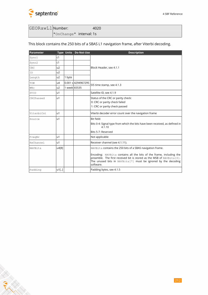
4 SBF Reference
GEORawL1 Number: 4020
"OnChange" interval: 1s
This block contains the 250 bits of a SBAS L1 navigation frame, after Viterbi decoding.
Parameter Type Units Do-Not-Use Description
Sync1 c1
Block Header, see 4.1.1
Sync2 c1
CRC u2
ID u2
Length u2 1 byte
TOW u4 0.001 s 4294967295SIS time stamp, see 4.1.3
WNc u2 1 week 65535
SVID u1 Satellite ID, see 4.1.9
CRCPassed u1 Status of the CRC or parity check:
0: CRC or parity check failed
1: CRC or parity check passed
ViterbiCnt u1 Viterbi decoder error count over the navigation frame
Source u1 Bit field:
Bits 0-4: Signal type from which the bits have been received, as defined in
4.1.10
Bits 5-7: Reserved
FreqNr u1 Not applicable
RxChannel u1 Receiver channel (see 4.1.11).
NAVBits u4[8] NAVBits contains the 250 bits of a SBAS navigation frame.
Encoding: NAVBits contains all the bits of the frame, including thepreamble. The first received bit is stored as the MSB of NAVBits[0].The unused bits in NAVBits[7] must be ignored by the decodingsoftware.
Padding u1[..] Padding bytes, see 4.1.5
212
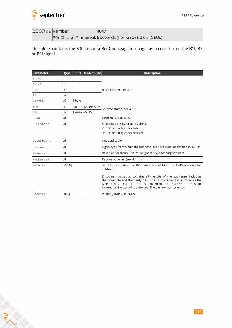
4 SBF Reference
BDSRaw Number: 4047
"OnChange" interval: 6 seconds (non GEOs), 0.6 s (GEOs)
This block contains the 300 bits of a BeiDou navigation page, as received from the B1I, B2I
or B3I signal.
Parameter Type Units Do-Not-Use Description
Sync1 c1
Block Header, see 4.1.1
Sync2 c1
CRC u2
ID u2
Length u2 1 byte
TOW u4 0.001 s 4294967295SIS time stamp, see 4.1.3
WNc u2 1 week 65535
SVID u1 Satellite ID, see 4.1.9
CRCPassed u1 Status of the CRC or parity check:
0: CRC or parity check failed
1: CRC or parity check passed
ViterbiCnt u1 Not applicable
Source u1 Signal type from which the bits have been received, as defined in 4.1.10
Reserved u1 Reserved for future use, to be ignored by decoding software.
RxChannel u1 Receiver channel (see 4.1.11).
NAVBits u4[10] NAVBits contains the 300 deinterleaved bits of a BeiDou navigationsubframe.
Encoding: NAVBits contains all the bits of the subframe, includingthe preamble and the parity bits. The first received bit is stored as the
MSB of NAVBits[0]. The 20 unused bits in NAVBits[9] must beignored by the decoding software. The bits are deinterleaved.
Padding u1[..] Padding bytes, see 4.1.5
213
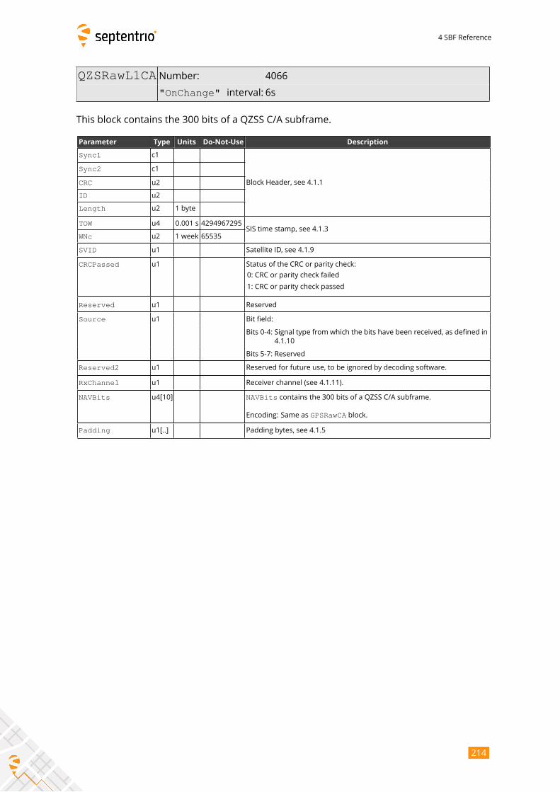
4 SBF Reference
QZSRawL1CA Number: 4066
"OnChange" interval: 6s
This block contains the 300 bits of a QZSS C/A subframe.
Parameter Type Units Do-Not-Use Description
Sync1 c1
Block Header, see 4.1.1
Sync2 c1
CRC u2
ID u2
Length u2 1 byte
TOW u4 0.001 s 4294967295SIS time stamp, see 4.1.3
WNc u2 1 week 65535
SVID u1 Satellite ID, see 4.1.9
CRCPassed u1 Status of the CRC or parity check:
0: CRC or parity check failed
1: CRC or parity check passed
Reserved u1 Reserved
Source u1 Bit field:
Bits 0-4: Signal type from which the bits have been received, as defined in
4.1.10
Bits 5-7: Reserved
Reserved2 u1 Reserved for future use, to be ignored by decoding software.
RxChannel u1 Receiver channel (see 4.1.11).
NAVBits u4[10] NAVBits contains the 300 bits of a QZSS C/A subframe.
Encoding: Same as GPSRawCA block.
Padding u1[..] Padding bytes, see 4.1.5
214
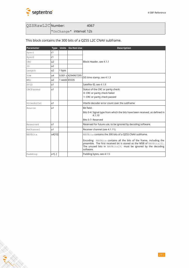
4 SBF Reference
QZSRawL2C Number: 4067
"OnChange" interval: 12s
This block contains the 300 bits of a QZSS L2C CNAV subframe.
Parameter Type Units Do-Not-Use Description
Sync1 c1
Block Header, see 4.1.1
Sync2 c1
CRC u2
ID u2
Length u2 1 byte
TOW u4 0.001 s 4294967295SIS time stamp, see 4.1.3
WNc u2 1 week 65535
SVID u1 Satellite ID, see 4.1.9
CRCPassed u1 Status of the CRC or parity check:
0: CRC or parity check failed
1: CRC or parity check passed
ViterbiCnt u1 Viterbi decoder error count over the subframe
Source u1 Bit field:
Bits 0-4: Signal type from which the bits have been received, as defined in
4.1.10
Bits 5-7: Reserved
Reserved u1 Reserved for future use, to be ignored by decoding software.
RxChannel u1 Receiver channel (see 4.1.11).
NAVBits u4[10] NAVBits contains the 300 bits of a QZSS CNAV subframe.
Encoding: NAVBits contains all the bits of the frame, including thepreamble. The first received bit is stored as the MSB of NAVBits[0].The unused bits in NAVBits[9] must be ignored by the decodingsoftware.
Padding u1[..] Padding bytes, see 4.1.5
215
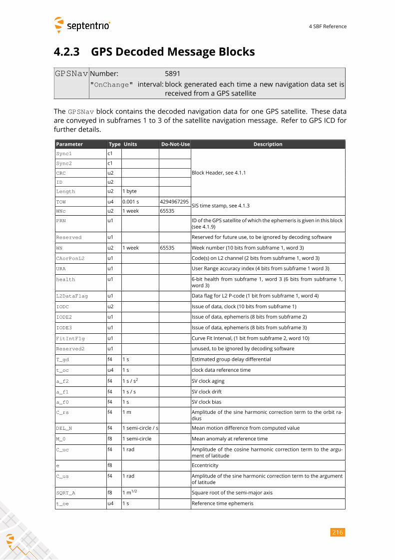
4 SBF Reference
4.2.3 GPS Decoded Message Blocks
GPSNav Number: 5891
"OnChange" interval: block generated each time a new navigation data set isreceived from a GPS satellite
The GPSNav block contains the decoded navigation data for one GPS satellite. These dataare conveyed in subframes 1 to 3 of the satellite navigation message. Refer to GPS ICD for
further details.
Parameter Type Units Do-Not-Use Description
Sync1 c1
Block Header, see 4.1.1
Sync2 c1
CRC u2
ID u2
Length u2 1 byte
TOW u4 0.001 s 4294967295SIS time stamp, see 4.1.3
WNc u2 1 week 65535
PRN u1 ID of the GPS satellite of which the ephemeris is given in this block
(see 4.1.9)
Reserved u1 Reserved for future use, to be ignored by decoding software
WN u2 1 week 65535 Week number (10 bits from subframe 1, word 3)
CAorPonL2 u1 Code(s) on L2 channel (2 bits from subframe 1, word 3)
URA u1 User Range accuracy index (4 bits from subframe 1 word 3)
health u1 6-bit health from subframe 1, word 3 (6 bits from subframe 1,
word 3)
L2DataFlag u1 Data flag for L2 P-code (1 bit from subframe 1, word 4)
IODC u2 Issue of data, clock (10 bits from subframe 1)
IODE2 u1 Issue of data, ephemeris (8 bits from subframe 2)
IODE3 u1 Issue of data, ephemeris (8 bits from subframe 3)
FitIntFlg u1 Curve Fit Interval, (1 bit from subframe 2, word 10)
Reserved2 u1 unused, to be ignored by decoding software
T_gd f4 1 s Estimated group delay differential
t_oc u4 1 s clock data reference time
a_f2 f4 1 s / s2
SV clock aging
a_f1 f4 1 s / s SV clock drift
a_f0 f4 1 s SV clock bias
C_rs f4 1 m Amplitude of the sine harmonic correction term to the orbit ra-
dius
DEL_N f4 1 semi-circle / s Mean motion difference from computed value
M_0 f8 1 semi-circle Mean anomaly at reference time
C_uc f4 1 rad Amplitude of the cosine harmonic correction term to the argu-
ment of latitude
e f8 Eccentricity
C_us f4 1 rad Amplitude of the sine harmonic correction term to the argument
of latitude
SQRT_A f8 1 m1/2
Square root of the semi-major axis
t_oe u4 1 s Reference time ephemeris
216
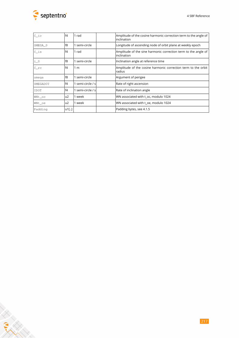
4 SBF Reference
C_ic f4 1 rad Amplitude of the cosine harmonic correction term to the angle of
inclination
OMEGA_0 f8 1 semi-circle Longitude of ascending node of orbit plane at weekly epoch
C_is f4 1 rad Amplitude of the sine harmonic correction term to the angle of
inclination
i_0 f8 1 semi-circle Inclination angle at reference time
C_rc f4 1 m Amplitude of the cosine harmonic correction term to the orbit
radius
omega f8 1 semi-circle Argument of perigee
OMEGADOT f4 1 semi-circle / s Rate of right ascension
IDOT f4 1 semi-circle / s Rate of inclination angle
WNt_oc u2 1 week WN associated with t_oc, modulo 1024
WNt_oe u2 1 week WN associated with t_oe, modulo 1024
Padding u1[..] Padding bytes, see 4.1.5
217
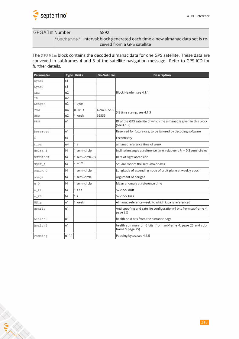
4 SBF Reference
GPSAlm Number: 5892
"OnChange" interval: block generated each time a new almanac data set is re-ceived from a GPS satellite
The GPSAlm block contains the decoded almanac data for one GPS satellite. These data areconveyed in subframes 4 and 5 of the satellite navigation message. Refer to GPS ICD for
further details.
Parameter Type Units Do-Not-Use Description
Sync1 c1
Block Header, see 4.1.1
Sync2 c1
CRC u2
ID u2
Length u2 1 byte
TOW u4 0.001 s 4294967295SIS time stamp, see 4.1.3
WNc u2 1 week 65535
PRN u1 ID of the GPS satellite of which the almanac is given in this block
(see 4.1.9)
Reserved u1 Reserved for future use, to be ignored by decoding software
e f4 Eccentricity
t_oa u4 1 s almanac reference time of week
delta_i f4 1 semi-circle Inclination angle at reference time, relative to i0 = 0.3 semi-circlesOMEGADOT f4 1 semi-circle / s Rate of right ascension
SQRT_A f4 1 m1/2
Square root of the semi-major axis
OMEGA_0 f4 1 semi-circle Longitude of ascending node of orbit plane at weekly epoch
omega f4 1 semi-circle Argument of perigee
M_0 f4 1 semi-circle Mean anomaly at reference time
a_f1 f4 1 s / s SV clock drift
a_f0 f4 1 s SV clock bias
WN_a u1 1 week Almanac reference week, to which t_oa is referenced
config u1 Anti-spoofing and satellite configuration (4 bits from subframe 4,
page 25)
health8 u1 health on 8 bits from the almanac page
health6 u1 health summary on 6 bits (from subframe 4, page 25 and sub-
frame 5 page 25)
Padding u1[..] Padding bytes, see 4.1.5
218
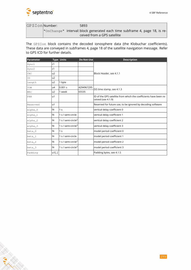
4 SBF Reference
GPSIon Number: 5893
"OnChange" interval: block generated each time subframe 4, page 18, is re-ceived from a GPS satellite
The GPSIon block contains the decoded ionosphere data (the Klobuchar coefficients).These data are conveyed in subframes 4, page 18 of the satellite navigation message. Refer
to GPS ICD for further details.
Parameter Type Units Do-Not-Use Description
Sync1 c1
Block Header, see 4.1.1
Sync2 c1
CRC u2
ID u2
Length u2 1 byte
TOW u4 0.001 s 4294967295SIS time stamp, see 4.1.3
WNc u2 1 week 65535
PRN u1 ID of the GPS satellite from which the coefficients have been re-
ceived (see 4.1.9)
Reserved u1 Reserved for future use, to be ignored by decoding software
alpha_0 f4 1 s vertical delay coefficient 0
alpha_1 f4 1 s / semi-circle vertical delay coefficient 1
alpha_2 f4 1 s / semi-circle2
vertical delay coefficient 2
alpha_3 f4 1 s / semi-circle3
vertical delay coefficient 3
beta_0 f4 1 s model period coefficient 0
beta_1 f4 1 s / semi-circle model period coefficient 1
beta_2 f4 1 s / semi-circle2
model period coefficient 2
beta_3 f4 1 s / semi-circle3
model period coefficient 3
Padding u1[..] Padding bytes, see 4.1.5
219
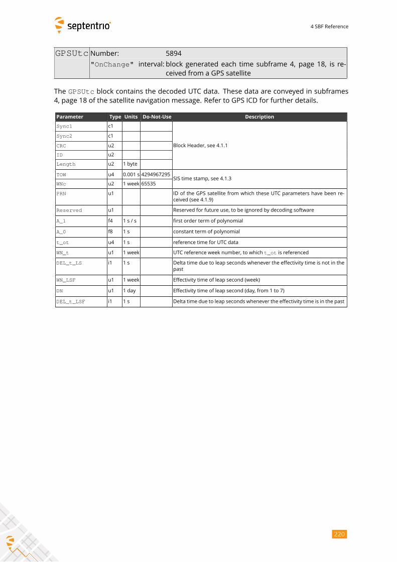
4 SBF Reference
GPSUtc Number: 5894
"OnChange" interval: block generated each time subframe 4, page 18, is re-ceived from a GPS satellite
The GPSUtc block contains the decoded UTC data. These data are conveyed in subframes4, page 18 of the satellite navigation message. Refer to GPS ICD for further details.
Parameter Type Units Do-Not-Use Description
Sync1 c1
Block Header, see 4.1.1
Sync2 c1
CRC u2
ID u2
Length u2 1 byte
TOW u4 0.001 s 4294967295SIS time stamp, see 4.1.3
WNc u2 1 week 65535
PRN u1 ID of the GPS satellite from which these UTC parameters have been re-
ceived (see 4.1.9)
Reserved u1 Reserved for future use, to be ignored by decoding software
A_1 f4 1 s / s first order term of polynomial
A_0 f8 1 s constant term of polynomial
t_ot u4 1 s reference time for UTC data
WN_t u1 1 week UTC reference week number, to which t_ot is referenced
DEL_t_LS i1 1 s Delta time due to leap seconds whenever the effectivity time is not in the
past
WN_LSF u1 1 week Effectivity time of leap second (week)
DN u1 1 day Effectivity time of leap second (day, from 1 to 7)
DEL_t_LSF i1 1 s Delta time due to leap seconds whenever the effectivity time is in the past
220
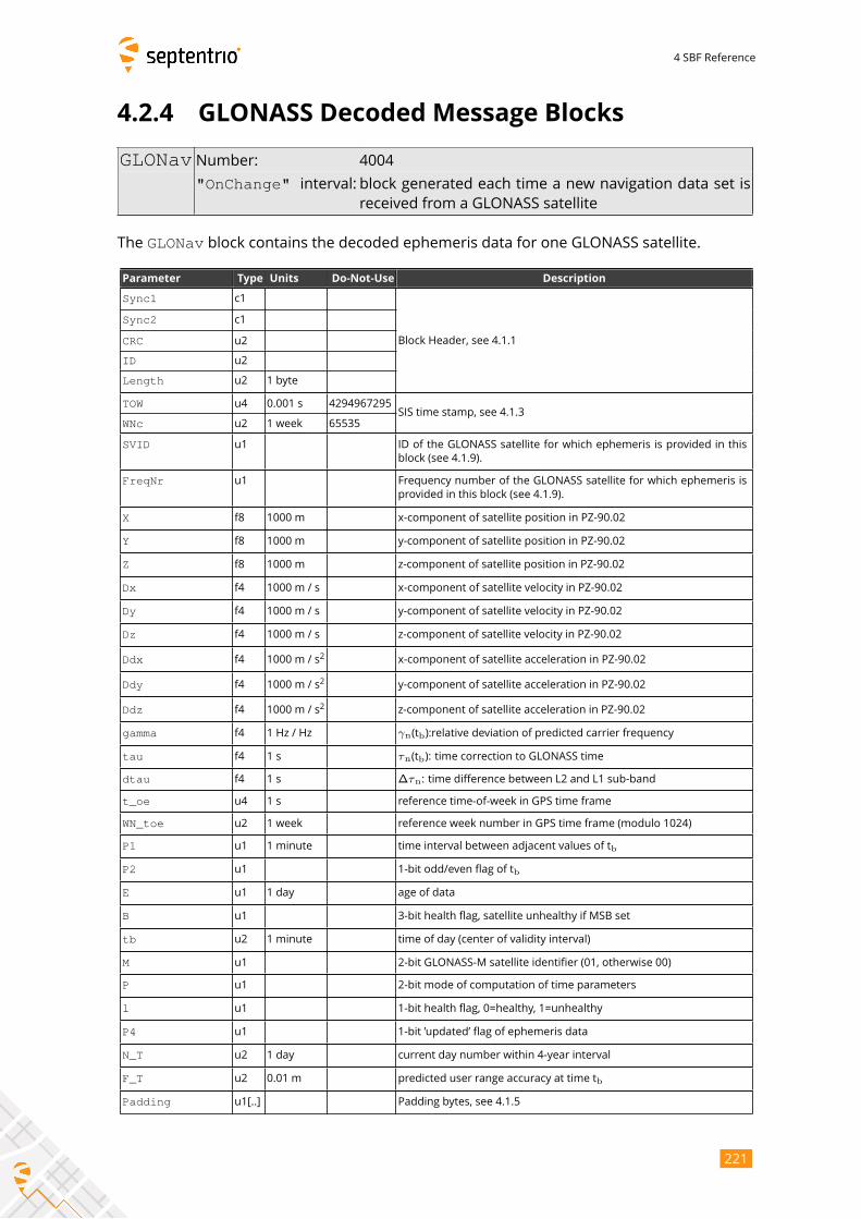
4 SBF Reference
4.2.4 GLONASS Decoded Message Blocks
GLONav Number: 4004
"OnChange" interval: block generated each time a new navigation data set isreceived from a GLONASS satellite
The GLONav block contains the decoded ephemeris data for one GLONASS satellite.
Parameter Type Units Do-Not-Use Description
Sync1 c1
Block Header, see 4.1.1
Sync2 c1
CRC u2
ID u2
Length u2 1 byte
TOW u4 0.001 s 4294967295SIS time stamp, see 4.1.3
WNc u2 1 week 65535
SVID u1 ID of the GLONASS satellite for which ephemeris is provided in this
block (see 4.1.9).
FreqNr u1 Frequency number of the GLONASS satellite for which ephemeris is
provided in this block (see 4.1.9).
X f8 1000 m x-component of satellite position in PZ-90.02
Y f8 1000 m y-component of satellite position in PZ-90.02
Z f8 1000 m z-component of satellite position in PZ-90.02
Dx f4 1000 m / s x-component of satellite velocity in PZ-90.02
Dy f4 1000 m / s y-component of satellite velocity in PZ-90.02
Dz f4 1000 m / s z-component of satellite velocity in PZ-90.02
Ddx f4 1000 m / s2
x-component of satellite acceleration in PZ-90.02
Ddy f4 1000 m / s2
y-component of satellite acceleration in PZ-90.02
Ddz f4 1000 m / s2
z-component of satellite acceleration in PZ-90.02
gamma f4 1 Hz / Hz γn(tb):relative deviation of predicted carrier frequency
tau f4 1 s τn(tb): time correction to GLONASS time
dtau f4 1 s ∆τn: time difference between L2 and L1 sub-band
t_oe u4 1 s reference time-of-week in GPS time frame
WN_toe u2 1 week reference week number in GPS time frame (modulo 1024)
P1 u1 1 minute time interval between adjacent values of tb
P2 u1 1-bit odd/even flag of tb
E u1 1 day age of data
B u1 3-bit health flag, satellite unhealthy if MSB set
tb u2 1 minute time of day (center of validity interval)
M u1 2-bit GLONASS-M satellite identifier (01, otherwise 00)
P u1 2-bit mode of computation of time parameters
l u1 1-bit health flag, 0=healthy, 1=unhealthy
P4 u1 1-bit ’updated’ flag of ephemeris data
N_T u2 1 day current day number within 4-year interval
F_T u2 0.01 m predicted user range accuracy at time tb
Padding u1[..] Padding bytes, see 4.1.5
221
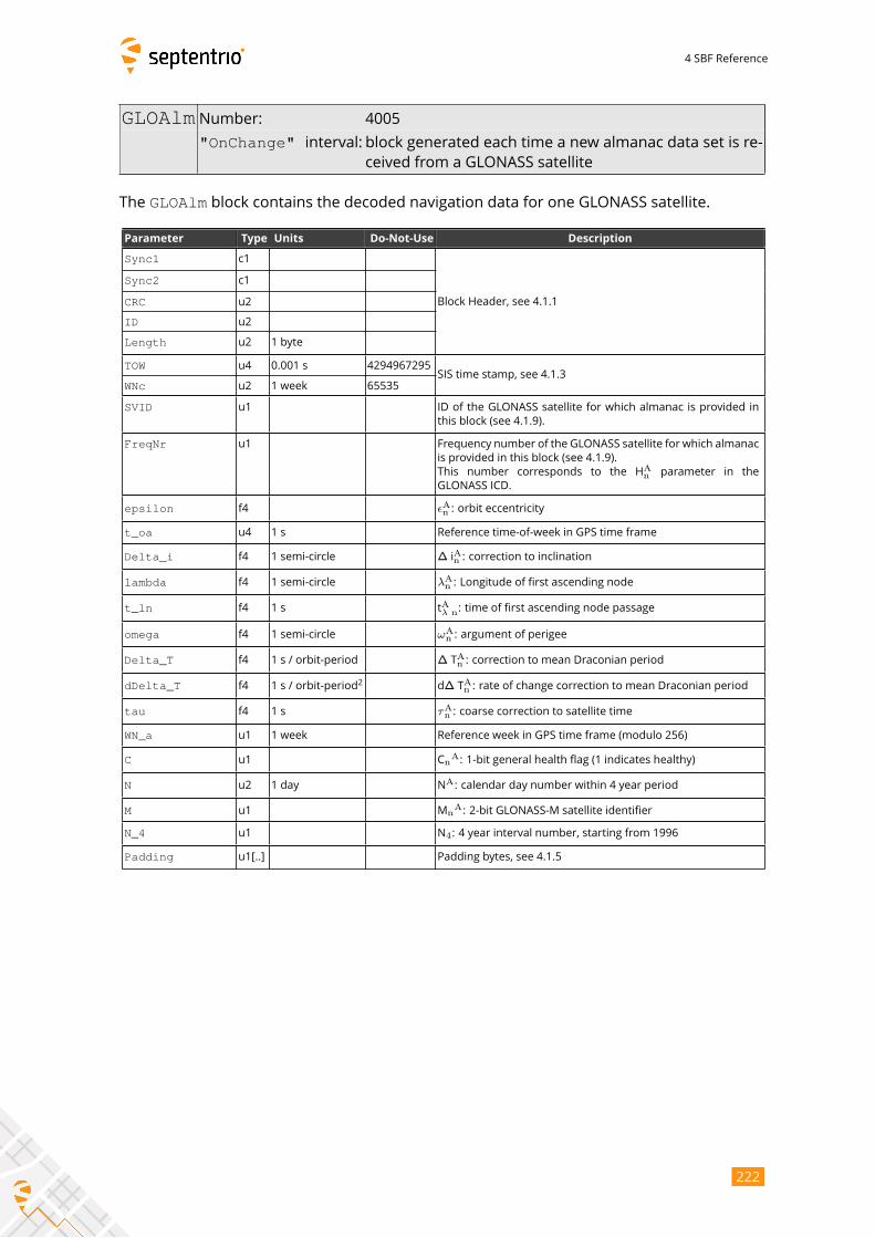
4 SBF Reference
GLOAlm Number: 4005
"OnChange" interval: block generated each time a new almanac data set is re-ceived from a GLONASS satellite
The GLOAlm block contains the decoded navigation data for one GLONASS satellite.
Parameter Type Units Do-Not-Use Description
Sync1 c1
Block Header, see 4.1.1
Sync2 c1
CRC u2
ID u2
Length u2 1 byte
TOW u4 0.001 s 4294967295SIS time stamp, see 4.1.3
WNc u2 1 week 65535
SVID u1 ID of the GLONASS satellite for which almanac is provided in
this block (see 4.1.9).
FreqNr u1 Frequency number of the GLONASS satellite for which almanac
is provided in this block (see 4.1.9).
This number corresponds to the HAn parameter in the
GLONASS ICD.
epsilon f4 ϵAn : orbit eccentricity
t_oa u4 1 s Reference time-of-week in GPS time frame
Delta_i f4 1 semi-circle ∆ iAn : correction to inclination
lambda f4 1 semi-circle λAn : Longitude of first ascending node
t_ln f4 1 s tAλ n: time of first ascending node passage
omega f4 1 semi-circle ωAn : argument of perigee
Delta_T f4 1 s / orbit-period ∆ TAn : correction to mean Draconian period
dDelta_T f4 1 s / orbit-period2
d∆ TAn : rate of change correction to mean Draconian period
tau f4 1 s τAn : coarse correction to satellite time
WN_a u1 1 week Reference week in GPS time frame (modulo 256)
C u1 CnA: 1-bit general health flag (1 indicates healthy)
N u2 1 day NA: calendar day number within 4 year period
M u1 MnA: 2-bit GLONASS-M satellite identifier
N_4 u1 N4: 4 year interval number, starting from 1996
Padding u1[..] Padding bytes, see 4.1.5
222
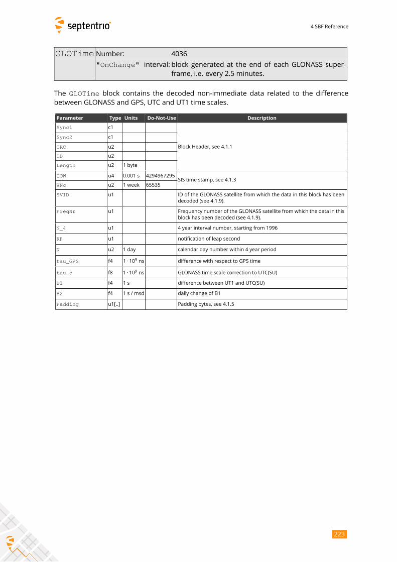
4 SBF Reference
GLOTime Number: 4036
"OnChange" interval: block generated at the end of each GLONASS super-frame, i.e. every 2.5 minutes.
The GLOTime block contains the decoded non-immediate data related to the differencebetween GLONASS and GPS, UTC and UT1 time scales.
Parameter Type Units Do-Not-Use Description
Sync1 c1
Block Header, see 4.1.1
Sync2 c1
CRC u2
ID u2
Length u2 1 byte
TOW u4 0.001 s 4294967295SIS time stamp, see 4.1.3
WNc u2 1 week 65535
SVID u1 ID of the GLONASS satellite from which the data in this block has been
decoded (see 4.1.9).
FreqNr u1 Frequency number of the GLONASS satellite from which the data in this
block has been decoded (see 4.1.9).
N_4 u1 4 year interval number, starting from 1996
KP u1 notification of leap second
N u2 1 day calendar day number within 4 year period
tau_GPS f4 1 · 109ns difference with respect to GPS time
tau_c f8 1 · 109ns GLONASS time scale correction to UTC(SU)
B1 f4 1 s difference between UT1 and UTC(SU)
B2 f4 1 s / msd daily change of B1
Padding u1[..] Padding bytes, see 4.1.5
223
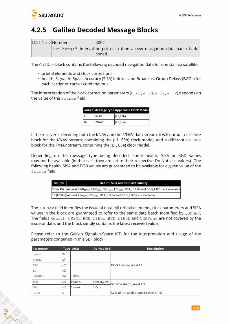
4 SBF Reference
4.2.5 Galileo Decoded Message Blocks
GALNav Number: 4002
"OnChange" interval: output each time a new navigation data batch is de-coded.
The GalNav block contains the following decoded navigation data for one Galileo satellite:
• orbital elements and clock corrections
• health, Signal-In-Space Accuracy (SISA) indexes and Broadcast Group Delays (BGDs) for
each carrier or carrier combinations.
The interpretation of the clock correction parameters (t_oc, a_f0, a_f1, a_f2) depends onthe value of the Source field:
Source Message type Applicable Clock Model
2 I/NAV (L1,E5b)
16 F/NAV (L1,E5a)
If the receiver is decoding both the I/NAV and the F/NAV data stream, it will output a GalNavblock for the I/NAV stream, containing the (L1, E5b) clock model, and a different GalNavblock for the F/NAV stream, containing the (L1, E5a) clock model.
Depending on the message type being decoded, some health, SISA or BGD values
may not be available (in that case they are set to their respective Do-Not-Use values). The
following health, SISA and BGD values are guaranteed to be available for a given value of the
Source field:
Source Health, SISA and BGD availability
2 (I/NAV) At least L1-BDVS, L1-BHS, E5bDVS,E5bHS, SISA_L1E5b and BGD_L1E5b are available
16 (F/NAV) At least E5aDVS,E5aHS, SISA_L1E5a and BGD_L1E5a are available
The IODNav field identifies the issue of data. All orbital elements, clock parameters and SISAvalues in the block are guaranteed to refer to the same data batch identified by IODNav.The fields Health_OSSOL, BGD_L1E5a, BGD_L1E5b and CNAVenc are not covered by theissue of data, and the block simply contains the latest received value.
Please refer to the Galileo Signal-In-Space ICD for the interpretation and usage of the
parameters contained in this SBF block.
Parameter Type Units Do-Not-Use Description
Sync1 c1
Block Header, see 4.1.1
Sync2 c1
CRC u2
ID u2
Length u2 1 byte
TOW u4 0.001 s 4294967295SIS time stamp, see 4.1.3
WNc u2 1 week 65535
SVID u1 SVID of the Galileo satellite (see 4.1.9)
224
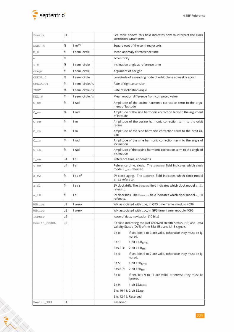
4 SBF Reference
Source u1 See table above: this field indicates how to interpret the clock
correction parameters.
SQRT_A f8 1 m1/2
Square root of the semi-major axis
M_0 f8 1 semi-circle Mean anomaly at reference time
e f8 Eccentricity
i_0 f8 1 semi-circle Inclination angle at reference time
omega f8 1 semi-circle Argument of perigee
OMEGA_0 f8 1 semi-circle Longitude of ascending node of orbit plane at weekly epoch
OMEGADOT f4 1 semi-circle / s Rate of right ascension
IDOT f4 1 semi-circle / s Rate of inclination angle
DEL_N f4 1 semi-circle / s Mean motion difference from computed value
C_uc f4 1 rad Amplitude of the cosine harmonic correction term to the argu-
ment of latitude
C_us f4 1 rad Amplitude of the sine harmonic correction term to the argument
of latitude
C_rc f4 1 m Amplitude of the cosine harmonic correction term to the orbit
radius
C_rs f4 1 m Amplitude of the sine harmonic correction term to the orbit ra-
dius
C_ic f4 1 rad Amplitude of the sine harmonic correction term to the angle of
inclination
C_is f4 1 rad Amplitude of the cosine harmonic correction term to the angle of
inclination
t_oe u4 1 s Reference time, ephemeris
t_oc u4 1 s Reference time, clock. The Source field indicates which clock
model t_oc refers to.
a_f2 f4 1 s / s2
SV clock aging. The Source field indicates which clock model
a_f2 refers to.
a_f1 f4 1 s / s SV clock drift. The Source field indicates which clockmodel a_f1refers to.
a_f0 f8 1 s SV clock bias. The Source field indicates which clockmodel a_f0refers to.
WNt_oe u2 1 week WN associated with t_oe, in GPS time frame, modulo 4096
WNt_oc u2 1 week WN associated with t_oc, in GPS time frame, modulo 4096
IODnav u2 Issue of data, navigation (10 bits)
Health_OSSOL u2 Bit field indicating the last received Health Status (HS) and Data
Validity Status (DVS) of the E5a, E5b and L1-B signals:
Bit 0: If set, bits 1 to 3 are valid, otherwise they must be ig-
nored.
Bit 1: 1-bit L1-BDVS
Bits 2-3: 2-bit L1-BHS
Bit 4: If set, bits 5 to 7 are valid, otherwise they must be ig-
nored.
Bit 5: 1-bit E5bDVS
Bits 6-7: 2-bit E5bHS
Bit 8: If set, bits 9 to 11 are valid, otherwise they must be
ignored.
Bit 9: 1-bit E5aDVS
Bits 10-11: 2-bit E5aHS
Bits 12-15: Reserved
Health_PRS u1 Reserved
225
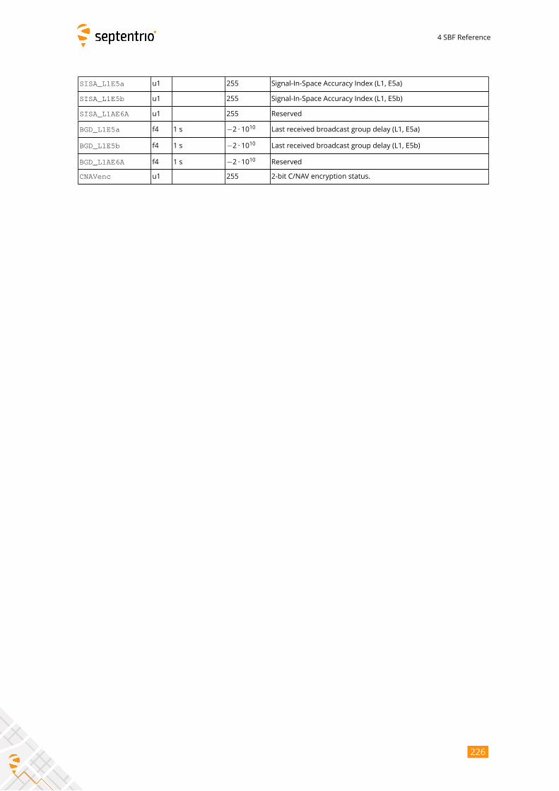
4 SBF Reference
SISA_L1E5a u1 255 Signal-In-Space Accuracy Index (L1, E5a)
SISA_L1E5b u1 255 Signal-In-Space Accuracy Index (L1, E5b)
SISA_L1AE6A u1 255 Reserved
BGD_L1E5a f4 1 s −2 · 1010 Last received broadcast group delay (L1, E5a)
BGD_L1E5b f4 1 s −2 · 1010 Last received broadcast group delay (L1, E5b)
BGD_L1AE6A f4 1 s −2 · 1010 Reserved
CNAVenc u1 255 2-bit C/NAV encryption status.
226
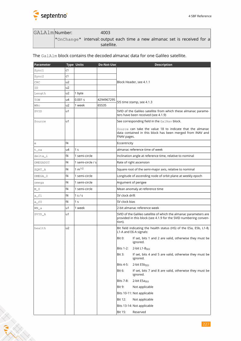
4 SBF Reference
GALAlm Number: 4003
"OnChange" interval: output each time a new almanac set is received for asatellite.
The GalAlm block contains the decoded almanac data for one Galileo satellite.
Parameter Type Units Do-Not-Use Description
Sync1 c1
Block Header, see 4.1.1
Sync2 c1
CRC u2
ID u2
Length u2 1 byte
TOW u4 0.001 s 4294967295SIS time stamp, see 4.1.3
WNc u2 1 week 65535
SVID u1 SVID of the Galileo satellite from which these almanac parame-
ters have been received (see 4.1.9)
Source u1 See corresponding field in the GalNav block.
Source can take the value 18 to indicate that the almanacdata contained in this block has been merged from INAV and
FNAV pages.
e f4 Eccentricity
t_oa u4 1 s almanac reference time of week
delta_i f4 1 semi-circle Inclination angle at reference time, relative to nominal
OMEGADOT f4 1 semi-circle / s Rate of right ascension
SQRT_A f4 1 m1/2
Square root of the semi-major axis, relative to nominal
OMEGA_0 f4 1 semi-circle Longitude of ascending node of orbit plane at weekly epoch
omega f4 1 semi-circle Argument of perigee
M_0 f4 1 semi-circle Mean anomaly at reference time
a_f1 f4 1 s / s SV clock drift
a_f0 f4 1 s SV clock bias
WN_a u1 1 week 2-bit almanac reference week
SVID_A u1 SVID of the Galileo satellite of which the almanac parameters are
provided in this block (see 4.1.9 for the SVID numbering conven-
tion).
health u2 Bit field indicating the health status (HS) of the E5a, E5b, L1-B,
L1-A and E6-A signals:
Bit 0: If set, bits 1 and 2 are valid, otherwise they must be
ignored.
Bits 1-2: 2-bit L1-BHS
Bit 3: If set, bits 4 and 5 are valid, otherwise they must be
ignored.
Bits 4-5: 2-bit E5bHS
Bit 6: If set, bits 7 and 8 are valid, otherwise they must be
ignored.
Bits 7-8: 2-bit E5aHS
Bit 9: Not applicable
Bits 10-11: Not applicable
Bit 12: Not applicable
Bits 13-14: Not applicable
Bit 15: Reserved
227

4 SBF Reference
IODa u1 4-bit Issue of Data for the almanac.
228
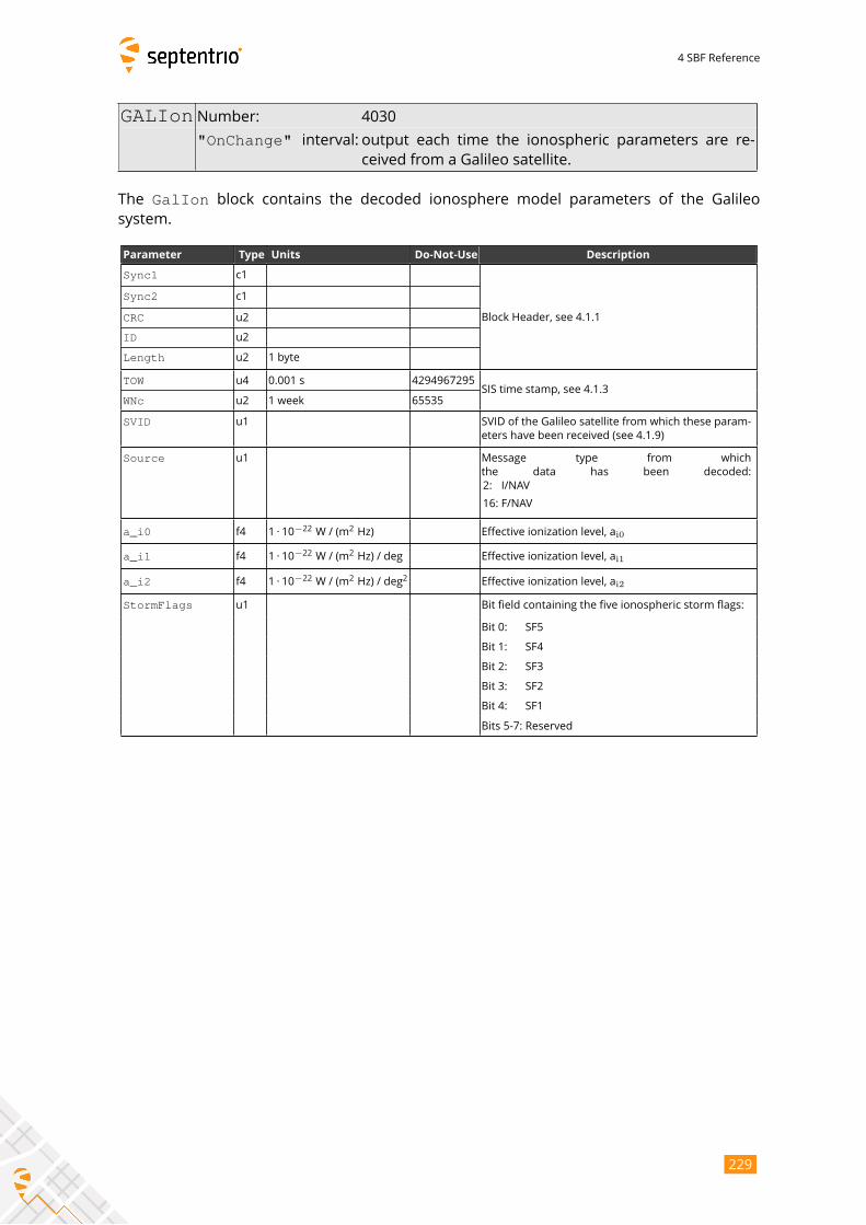
4 SBF Reference
GALIon Number: 4030
"OnChange" interval: output each time the ionospheric parameters are re-ceived from a Galileo satellite.
The GalIon block contains the decoded ionosphere model parameters of the Galileosystem.
Parameter Type Units Do-Not-Use Description
Sync1 c1
Block Header, see 4.1.1
Sync2 c1
CRC u2
ID u2
Length u2 1 byte
TOW u4 0.001 s 4294967295SIS time stamp, see 4.1.3
WNc u2 1 week 65535
SVID u1 SVID of the Galileo satellite from which these param-
eters have been received (see 4.1.9)
Source u1 Message type from which
the data has been decoded:
2: I/NAV
16: F/NAV
a_i0 f4 1 · 10−22
W / (m2Hz) Effective ionization level, ai0
a_i1 f4 1 · 10−22
W / (m2Hz) / deg Effective ionization level, ai1
a_i2 f4 1 · 10−22
W / (m2Hz) / deg
2Effective ionization level, ai2
StormFlags u1 Bit field containing the five ionospheric storm flags:
Bit 0: SF5
Bit 1: SF4
Bit 2: SF3
Bit 3: SF2
Bit 4: SF1
Bits 5-7: Reserved
229
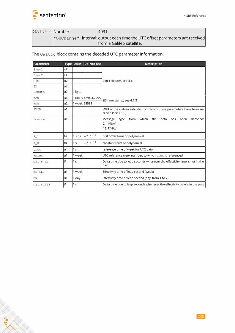
4 SBF Reference
GALUtc Number: 4031
"OnChange" interval: output each time the UTC offset parameters are receivedfrom a Galileo satellite.
The GalUtc block contains the decoded UTC parameter information.
Parameter Type Units Do-Not-Use Description
Sync1 c1
Block Header, see 4.1.1
Sync2 c1
CRC u2
ID u2
Length u2 1 byte
TOW u4 0.001 s 4294967295SIS time stamp, see 4.1.3
WNc u2 1 week 65535
SVID u1 SVID of the Galileo satellite from which these parameters have been re-
ceived (see 4.1.9)
Source u1 Message type from which the data has been decoded:
2: I/NAV
16: F/NAV
A_1 f4 1 s / s −2 · 1010 first order term of polynomial
A_0 f8 1 s −2 · 1010 constant term of polynomial
t_ot u4 1 s reference time of week for UTC data
WN_ot u1 1 week UTC reference week number, to which t_ot is referenced
DEL_t_LS i1 1 s Delta time due to leap seconds whenever the effectivity time is not in the
past
WN_LSF u1 1 week Effectivity time of leap second (week)
DN u1 1 day Effectivity time of leap second (day, from 1 to 7)
DEL_t_LSF i1 1 s Delta time due to leap seconds whenever the effectivity time is in the past
230
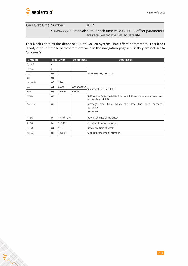
4 SBF Reference
GALGstGps Number: 4032
"OnChange" interval: output each time valid GST-GPS offset parametersare received from a Galileo satellite.
This block contains the decoded GPS to Galileo System Time offset parameters. This block
is only output if these parameters are valid in the navigation page (i.e. if they are not set to
"all ones").
Parameter Type Units Do-Not-Use Description
Sync1 c1
Block Header, see 4.1.1
Sync2 c1
CRC u2
ID u2
Length u2 1 byte
TOW u4 0.001 s 4294967295SIS time stamp, see 4.1.3
WNc u2 1 week 65535
SVID u1 SVID of the Galileo satellite from which these parameters have been
received (see 4.1.9)
Source u1 Message type from which the data has been decoded:
2: I/NAV
16: F/NAV
A_1G f4 1 · 109ns / s Rate of change of the offset
A_0G f4 1 · 109ns Constant term of the offset
t_oG u4 1 s Reference time of week
WN_oG u1 1 week 6-bit reference week number.
231
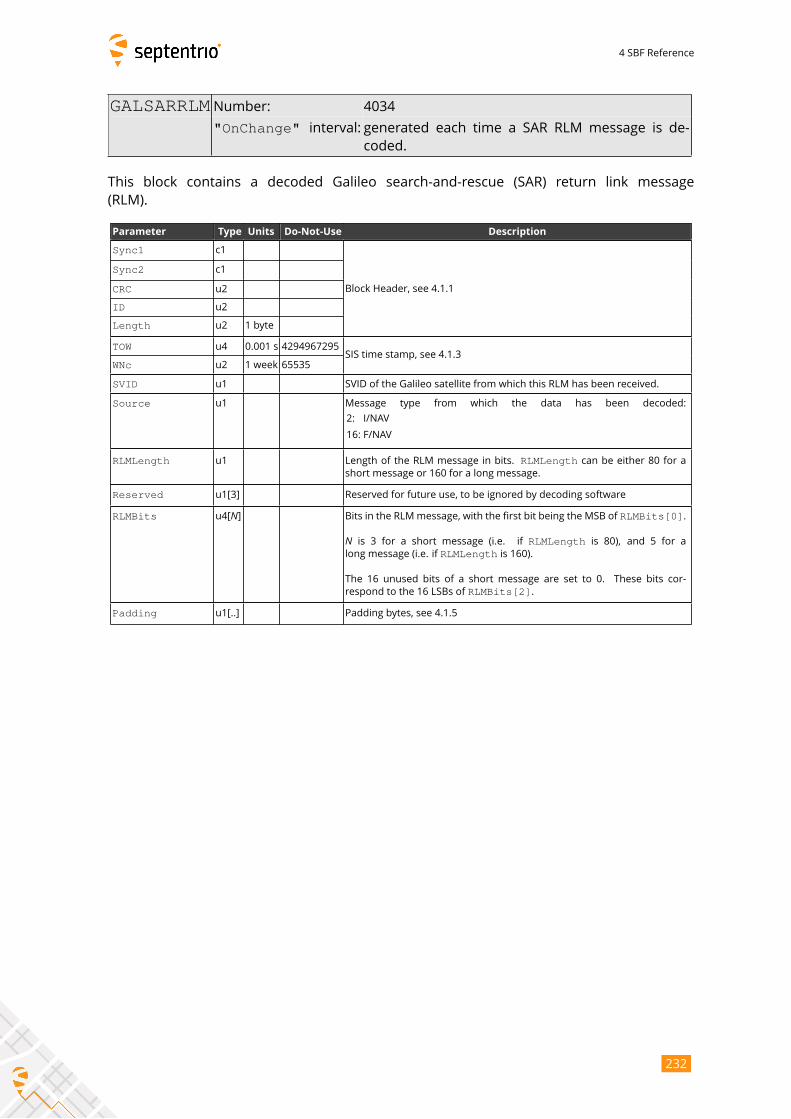
4 SBF Reference
GALSARRLM Number: 4034
"OnChange" interval: generated each time a SAR RLM message is de-
coded.
This block contains a decoded Galileo search-and-rescue (SAR) return link message
(RLM).
Parameter Type Units Do-Not-Use Description
Sync1 c1
Block Header, see 4.1.1
Sync2 c1
CRC u2
ID u2
Length u2 1 byte
TOW u4 0.001 s 4294967295SIS time stamp, see 4.1.3
WNc u2 1 week 65535
SVID u1 SVID of the Galileo satellite from which this RLM has been received.
Source u1 Message type from which the data has been decoded:
2: I/NAV
16: F/NAV
RLMLength u1 Length of the RLM message in bits. RLMLength can be either 80 for ashort message or 160 for a long message.
Reserved u1[3] Reserved for future use, to be ignored by decoding software
RLMBits u4[N] Bits in the RLMmessage, with the first bit being the MSB of RLMBits[0].
N is 3 for a short message (i.e. if RLMLength is 80), and 5 for along message (i.e. if RLMLength is 160).
The 16 unused bits of a short message are set to 0. These bits cor-
respond to the 16 LSBs of RLMBits[2].
Padding u1[..] Padding bytes, see 4.1.5
232
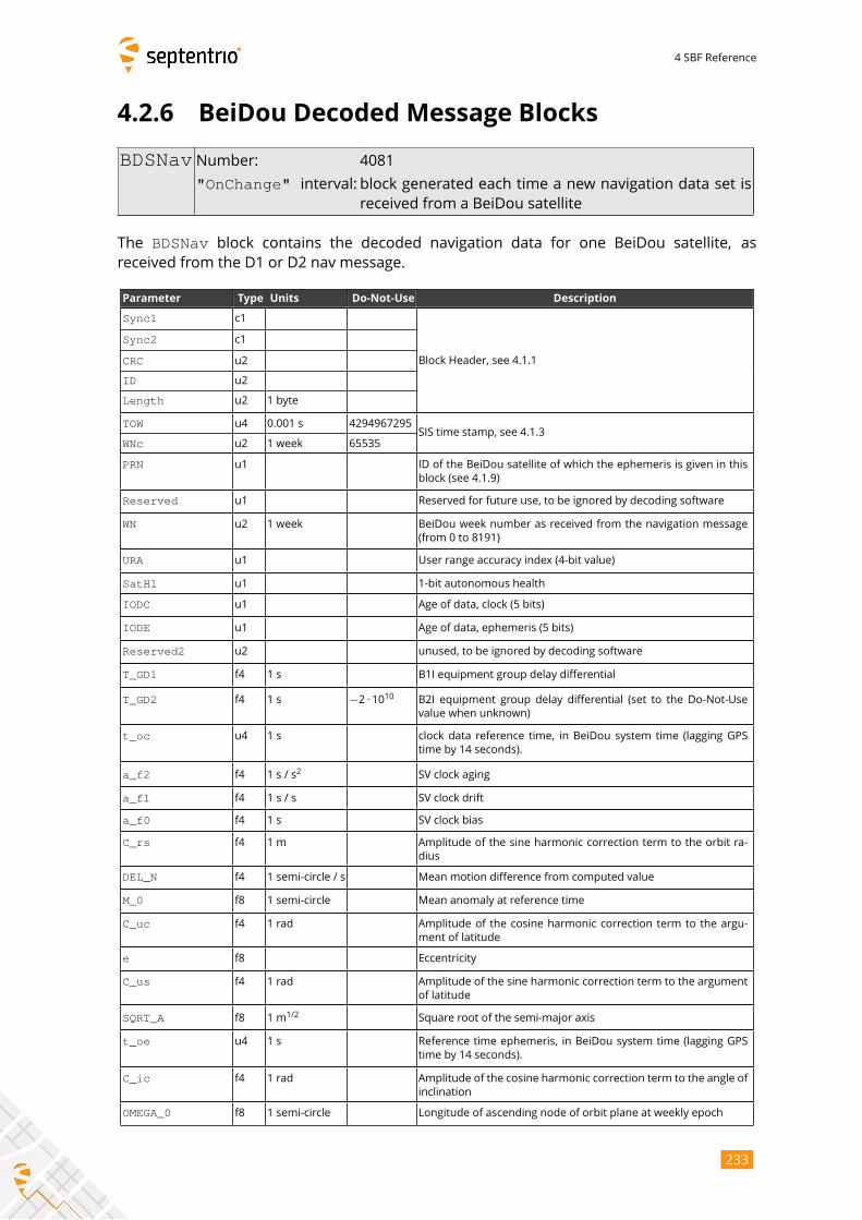
4 SBF Reference
4.2.6 BeiDou Decoded Message Blocks
BDSNav Number: 4081
"OnChange" interval: block generated each time a new navigation data set isreceived from a BeiDou satellite
The BDSNav block contains the decoded navigation data for one BeiDou satellite, asreceived from the D1 or D2 nav message.
Parameter Type Units Do-Not-Use Description
Sync1 c1
Block Header, see 4.1.1
Sync2 c1
CRC u2
ID u2
Length u2 1 byte
TOW u4 0.001 s 4294967295SIS time stamp, see 4.1.3
WNc u2 1 week 65535
PRN u1 ID of the BeiDou satellite of which the ephemeris is given in this
block (see 4.1.9)
Reserved u1 Reserved for future use, to be ignored by decoding software
WN u2 1 week BeiDou week number as received from the navigation message
(from 0 to 8191)
URA u1 User range accuracy index (4-bit value)
SatH1 u1 1-bit autonomous health
IODC u1 Age of data, clock (5 bits)
IODE u1 Age of data, ephemeris (5 bits)
Reserved2 u2 unused, to be ignored by decoding software
T_GD1 f4 1 s B1I equipment group delay differential
T_GD2 f4 1 s −2 · 1010 B2I equipment group delay differential (set to the Do-Not-Use
value when unknown)
t_oc u4 1 s clock data reference time, in BeiDou system time (lagging GPS
time by 14 seconds).
a_f2 f4 1 s / s2
SV clock aging
a_f1 f4 1 s / s SV clock drift
a_f0 f4 1 s SV clock bias
C_rs f4 1 m Amplitude of the sine harmonic correction term to the orbit ra-
dius
DEL_N f4 1 semi-circle / s Mean motion difference from computed value
M_0 f8 1 semi-circle Mean anomaly at reference time
C_uc f4 1 rad Amplitude of the cosine harmonic correction term to the argu-
ment of latitude
e f8 Eccentricity
C_us f4 1 rad Amplitude of the sine harmonic correction term to the argument
of latitude
SQRT_A f8 1 m1/2
Square root of the semi-major axis
t_oe u4 1 s Reference time ephemeris, in BeiDou system time (lagging GPS
time by 14 seconds).
C_ic f4 1 rad Amplitude of the cosine harmonic correction term to the angle of
inclination
OMEGA_0 f8 1 semi-circle Longitude of ascending node of orbit plane at weekly epoch
233
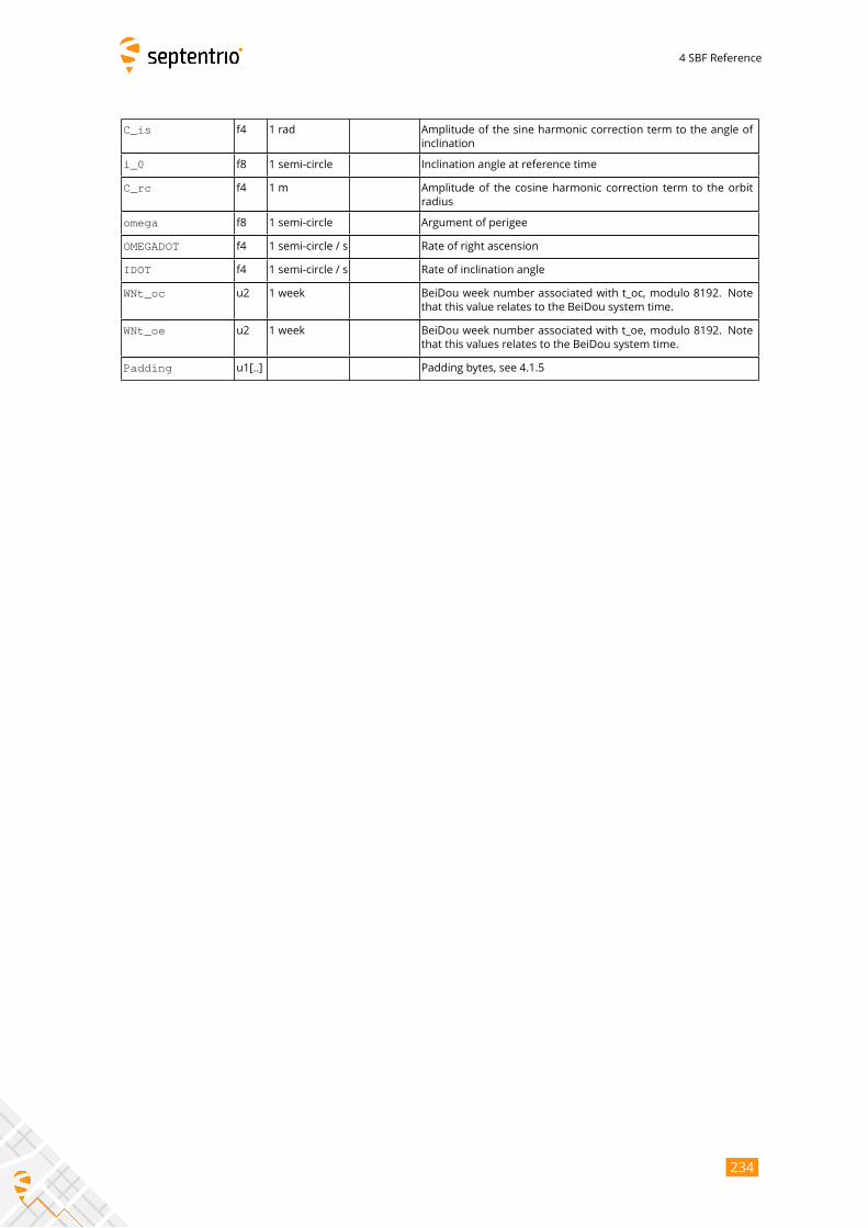
4 SBF Reference
C_is f4 1 rad Amplitude of the sine harmonic correction term to the angle of
inclination
i_0 f8 1 semi-circle Inclination angle at reference time
C_rc f4 1 m Amplitude of the cosine harmonic correction term to the orbit
radius
omega f8 1 semi-circle Argument of perigee
OMEGADOT f4 1 semi-circle / s Rate of right ascension
IDOT f4 1 semi-circle / s Rate of inclination angle
WNt_oc u2 1 week BeiDou week number associated with t_oc, modulo 8192. Note
that this value relates to the BeiDou system time.
WNt_oe u2 1 week BeiDou week number associated with t_oe, modulo 8192. Note
that this values relates to the BeiDou system time.
Padding u1[..] Padding bytes, see 4.1.5
234
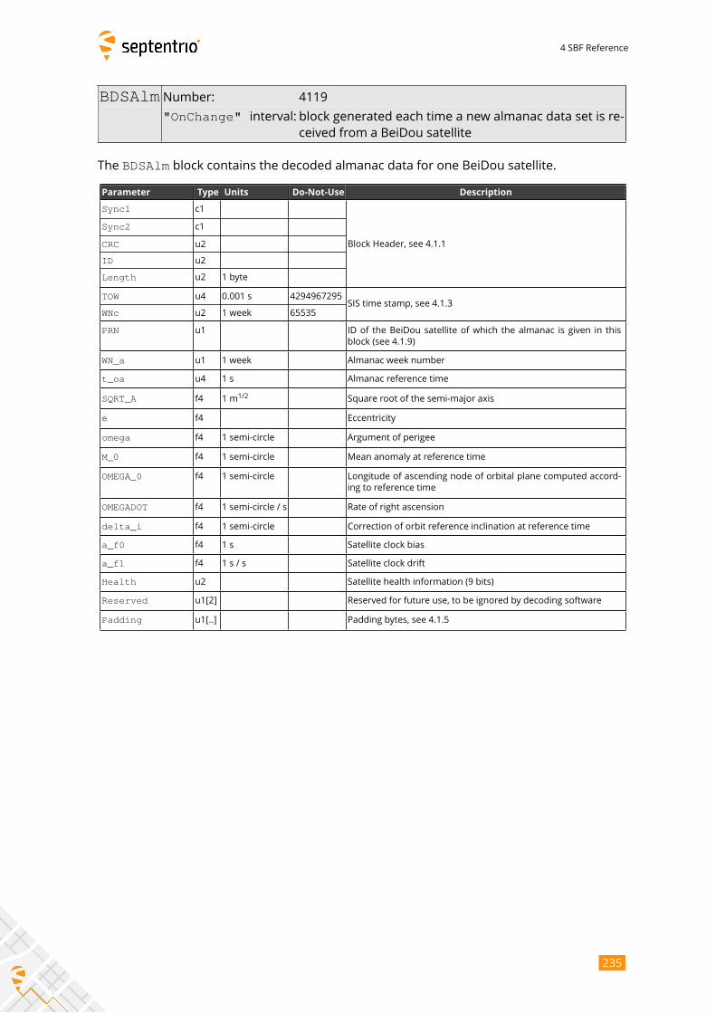
4 SBF Reference
BDSAlm Number: 4119
"OnChange" interval: block generated each time a new almanac data set is re-ceived from a BeiDou satellite
The BDSAlm block contains the decoded almanac data for one BeiDou satellite.
Parameter Type Units Do-Not-Use Description
Sync1 c1
Block Header, see 4.1.1
Sync2 c1
CRC u2
ID u2
Length u2 1 byte
TOW u4 0.001 s 4294967295SIS time stamp, see 4.1.3
WNc u2 1 week 65535
PRN u1 ID of the BeiDou satellite of which the almanac is given in this
block (see 4.1.9)
WN_a u1 1 week Almanac week number
t_oa u4 1 s Almanac reference time
SQRT_A f4 1 m1/2
Square root of the semi-major axis
e f4 Eccentricity
omega f4 1 semi-circle Argument of perigee
M_0 f4 1 semi-circle Mean anomaly at reference time
OMEGA_0 f4 1 semi-circle Longitude of ascending node of orbital plane computed accord-
ing to reference time
OMEGADOT f4 1 semi-circle / s Rate of right ascension
delta_i f4 1 semi-circle Correction of orbit reference inclination at reference time
a_f0 f4 1 s Satellite clock bias
a_f1 f4 1 s / s Satellite clock drift
Health u2 Satellite health information (9 bits)
Reserved u1[2] Reserved for future use, to be ignored by decoding software
Padding u1[..] Padding bytes, see 4.1.5
235
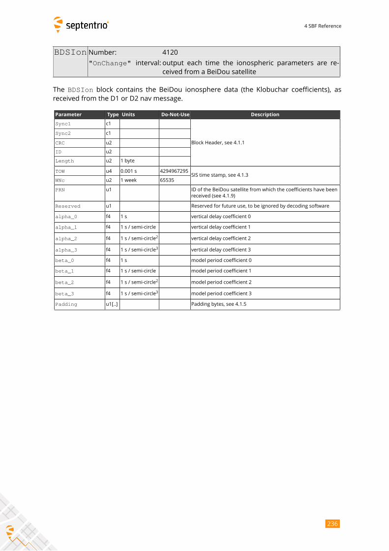
4 SBF Reference
BDSIon Number: 4120
"OnChange" interval: output each time the ionospheric parameters are re-ceived from a BeiDou satellite
The BDSIon block contains the BeiDou ionosphere data (the Klobuchar coefficients), asreceived from the D1 or D2 nav message.
Parameter Type Units Do-Not-Use Description
Sync1 c1
Block Header, see 4.1.1
Sync2 c1
CRC u2
ID u2
Length u2 1 byte
TOW u4 0.001 s 4294967295SIS time stamp, see 4.1.3
WNc u2 1 week 65535
PRN u1 ID of the BeiDou satellite from which the coefficients have been
received (see 4.1.9)
Reserved u1 Reserved for future use, to be ignored by decoding software
alpha_0 f4 1 s vertical delay coefficient 0
alpha_1 f4 1 s / semi-circle vertical delay coefficient 1
alpha_2 f4 1 s / semi-circle2
vertical delay coefficient 2
alpha_3 f4 1 s / semi-circle3
vertical delay coefficient 3
beta_0 f4 1 s model period coefficient 0
beta_1 f4 1 s / semi-circle model period coefficient 1
beta_2 f4 1 s / semi-circle2
model period coefficient 2
beta_3 f4 1 s / semi-circle3
model period coefficient 3
Padding u1[..] Padding bytes, see 4.1.5
236
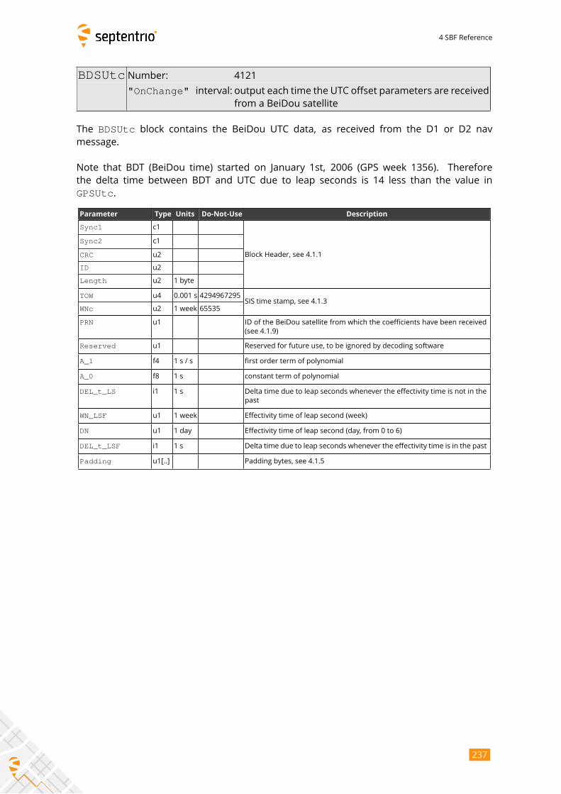
4 SBF Reference
BDSUtc Number: 4121
"OnChange" interval: output each time the UTC offset parameters are receivedfrom a BeiDou satellite
The BDSUtc block contains the BeiDou UTC data, as received from the D1 or D2 nav
message.
Note that BDT (BeiDou time) started on January 1st, 2006 (GPS week 1356). Therefore
the delta time between BDT and UTC due to leap seconds is 14 less than the value in
GPSUtc.
Parameter Type Units Do-Not-Use Description
Sync1 c1
Block Header, see 4.1.1
Sync2 c1
CRC u2
ID u2
Length u2 1 byte
TOW u4 0.001 s 4294967295SIS time stamp, see 4.1.3
WNc u2 1 week 65535
PRN u1 ID of the BeiDou satellite from which the coefficients have been received
(see 4.1.9)
Reserved u1 Reserved for future use, to be ignored by decoding software
A_1 f4 1 s / s first order term of polynomial
A_0 f8 1 s constant term of polynomial
DEL_t_LS i1 1 s Delta time due to leap seconds whenever the effectivity time is not in the
past
WN_LSF u1 1 week Effectivity time of leap second (week)
DN u1 1 day Effectivity time of leap second (day, from 0 to 6)
DEL_t_LSF i1 1 s Delta time due to leap seconds whenever the effectivity time is in the past
Padding u1[..] Padding bytes, see 4.1.5
237
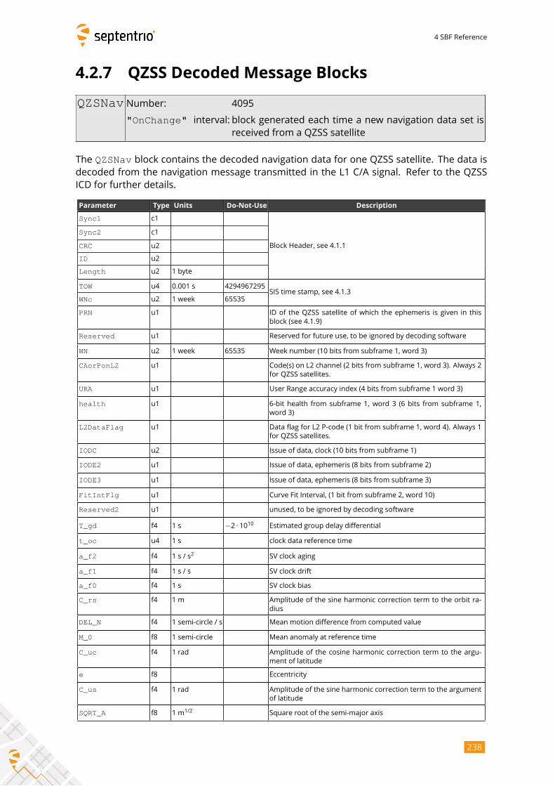
4 SBF Reference
4.2.7 QZSS Decoded Message Blocks
QZSNav Number: 4095
"OnChange" interval: block generated each time a new navigation data set isreceived from a QZSS satellite
The QZSNav block contains the decoded navigation data for one QZSS satellite. The data isdecoded from the navigation message transmitted in the L1 C/A signal. Refer to the QZSS
ICD for further details.
Parameter Type Units Do-Not-Use Description
Sync1 c1
Block Header, see 4.1.1
Sync2 c1
CRC u2
ID u2
Length u2 1 byte
TOW u4 0.001 s 4294967295SIS time stamp, see 4.1.3
WNc u2 1 week 65535
PRN u1 ID of the QZSS satellite of which the ephemeris is given in this
block (see 4.1.9)
Reserved u1 Reserved for future use, to be ignored by decoding software
WN u2 1 week 65535 Week number (10 bits from subframe 1, word 3)
CAorPonL2 u1 Code(s) on L2 channel (2 bits from subframe 1, word 3). Always 2
for QZSS satellites.
URA u1 User Range accuracy index (4 bits from subframe 1 word 3)
health u1 6-bit health from subframe 1, word 3 (6 bits from subframe 1,
word 3)
L2DataFlag u1 Data flag for L2 P-code (1 bit from subframe 1, word 4). Always 1
for QZSS satellites.
IODC u2 Issue of data, clock (10 bits from subframe 1)
IODE2 u1 Issue of data, ephemeris (8 bits from subframe 2)
IODE3 u1 Issue of data, ephemeris (8 bits from subframe 3)
FitIntFlg u1 Curve Fit Interval, (1 bit from subframe 2, word 10)
Reserved2 u1 unused, to be ignored by decoding software
T_gd f4 1 s −2 · 1010 Estimated group delay differential
t_oc u4 1 s clock data reference time
a_f2 f4 1 s / s2
SV clock aging
a_f1 f4 1 s / s SV clock drift
a_f0 f4 1 s SV clock bias
C_rs f4 1 m Amplitude of the sine harmonic correction term to the orbit ra-
dius
DEL_N f4 1 semi-circle / s Mean motion difference from computed value
M_0 f8 1 semi-circle Mean anomaly at reference time
C_uc f4 1 rad Amplitude of the cosine harmonic correction term to the argu-
ment of latitude
e f8 Eccentricity
C_us f4 1 rad Amplitude of the sine harmonic correction term to the argument
of latitude
SQRT_A f8 1 m1/2
Square root of the semi-major axis
238
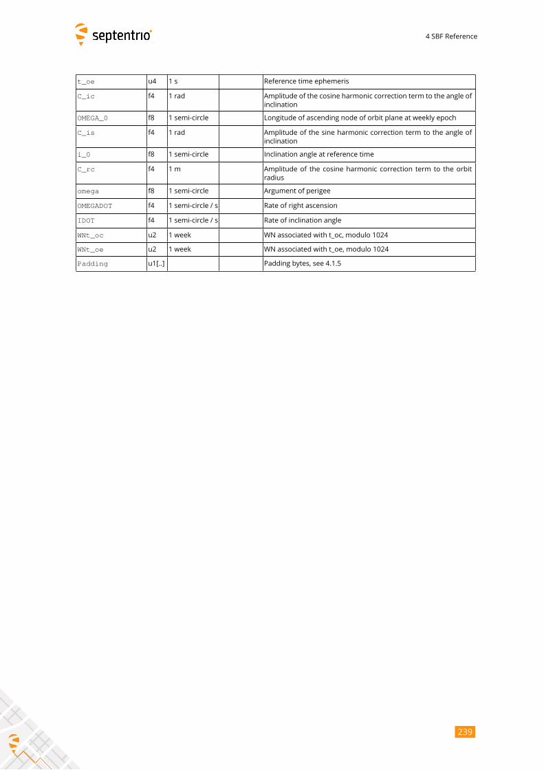
4 SBF Reference
t_oe u4 1 s Reference time ephemeris
C_ic f4 1 rad Amplitude of the cosine harmonic correction term to the angle of
inclination
OMEGA_0 f8 1 semi-circle Longitude of ascending node of orbit plane at weekly epoch
C_is f4 1 rad Amplitude of the sine harmonic correction term to the angle of
inclination
i_0 f8 1 semi-circle Inclination angle at reference time
C_rc f4 1 m Amplitude of the cosine harmonic correction term to the orbit
radius
omega f8 1 semi-circle Argument of perigee
OMEGADOT f4 1 semi-circle / s Rate of right ascension
IDOT f4 1 semi-circle / s Rate of inclination angle
WNt_oc u2 1 week WN associated with t_oc, modulo 1024
WNt_oe u2 1 week WN associated with t_oe, modulo 1024
Padding u1[..] Padding bytes, see 4.1.5
239
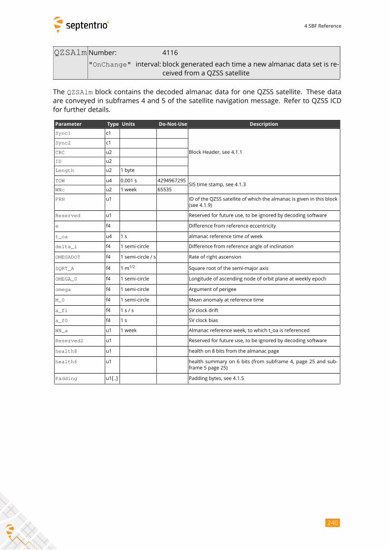
4 SBF Reference
QZSAlm Number: 4116
"OnChange" interval: block generated each time a new almanac data set is re-ceived from a QZSS satellite
The QZSAlm block contains the decoded almanac data for one QZSS satellite. These dataare conveyed in subframes 4 and 5 of the satellite navigation message. Refer to QZSS ICD
for further details.
Parameter Type Units Do-Not-Use Description
Sync1 c1
Block Header, see 4.1.1
Sync2 c1
CRC u2
ID u2
Length u2 1 byte
TOW u4 0.001 s 4294967295SIS time stamp, see 4.1.3
WNc u2 1 week 65535
PRN u1 ID of the QZSS satellite of which the almanac is given in this block
(see 4.1.9)
Reserved u1 Reserved for future use, to be ignored by decoding software
e f4 Difference from reference eccentricity
t_oa u4 1 s almanac reference time of week
delta_i f4 1 semi-circle Difference from reference angle of inclination
OMEGADOT f4 1 semi-circle / s Rate of right ascension
SQRT_A f4 1 m1/2
Square root of the semi-major axis
OMEGA_0 f4 1 semi-circle Longitude of ascending node of orbit plane at weekly epoch
omega f4 1 semi-circle Argument of perigee
M_0 f4 1 semi-circle Mean anomaly at reference time
a_f1 f4 1 s / s SV clock drift
a_f0 f4 1 s SV clock bias
WN_a u1 1 week Almanac reference week, to which t_oa is referenced
Reserved2 u1 Reserved for future use, to be ignored by decoding software
health8 u1 health on 8 bits from the almanac page
health6 u1 health summary on 6 bits (from subframe 4, page 25 and sub-
frame 5 page 25)
Padding u1[..] Padding bytes, see 4.1.5
240
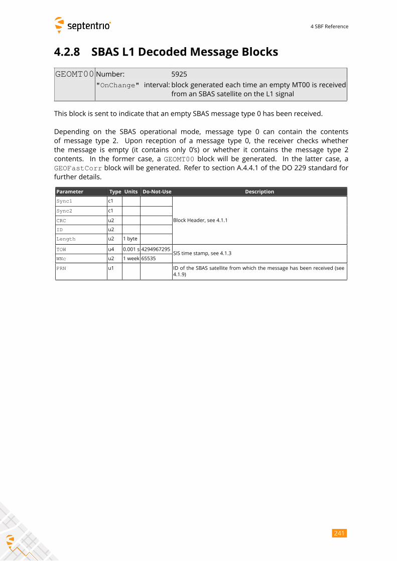
4 SBF Reference
4.2.8 SBAS L1 Decoded Message Blocks
GEOMT00 Number: 5925
"OnChange" interval: block generated each time an empty MT00 is receivedfrom an SBAS satellite on the L1 signal
This block is sent to indicate that an empty SBAS message type 0 has been received.
Depending on the SBAS operational mode, message type 0 can contain the contents
of message type 2. Upon reception of a message type 0, the receiver checks whether
the message is empty (it contains only 0’s) or whether it contains the message type 2
contents. In the former case, a GEOMT00 block will be generated. In the latter case, a
GEOFastCorr block will be generated. Refer to section A.4.4.1 of the DO 229 standard forfurther details.
Parameter Type Units Do-Not-Use Description
Sync1 c1
Block Header, see 4.1.1
Sync2 c1
CRC u2
ID u2
Length u2 1 byte
TOW u4 0.001 s 4294967295SIS time stamp, see 4.1.3
WNc u2 1 week 65535
PRN u1 ID of the SBAS satellite from which the message has been received (see
4.1.9)
241
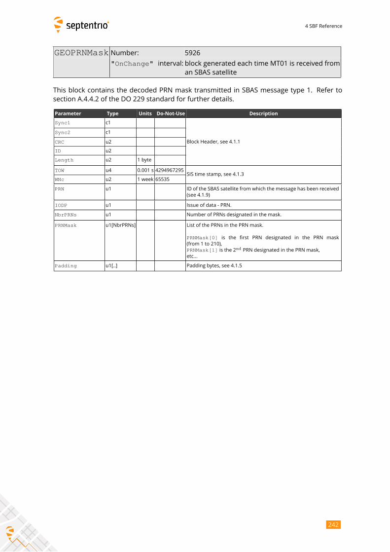
4 SBF Reference
GEOPRNMask Number: 5926
"OnChange" interval: block generated each time MT01 is received froman SBAS satellite
This block contains the decoded PRN mask transmitted in SBAS message type 1. Refer to
section A.4.4.2 of the DO 229 standard for further details.
Parameter Type Units Do-Not-Use Description
Sync1 c1
Block Header, see 4.1.1
Sync2 c1
CRC u2
ID u2
Length u2 1 byte
TOW u4 0.001 s 4294967295SIS time stamp, see 4.1.3
WNc u2 1 week 65535
PRN u1 ID of the SBAS satellite from which the message has been received
(see 4.1.9)
IODP u1 Issue of data - PRN.
NbrPRNs u1 Number of PRNs designated in the mask.
PRNMask u1[NbrPRNs] List of the PRNs in the PRN mask.
PRNMask[0] is the first PRN designated in the PRN mask
(from 1 to 210),
PRNMask[1] is the 2ndPRN designated in the PRN mask,
etc...
Padding u1[..] Padding bytes, see 4.1.5
242
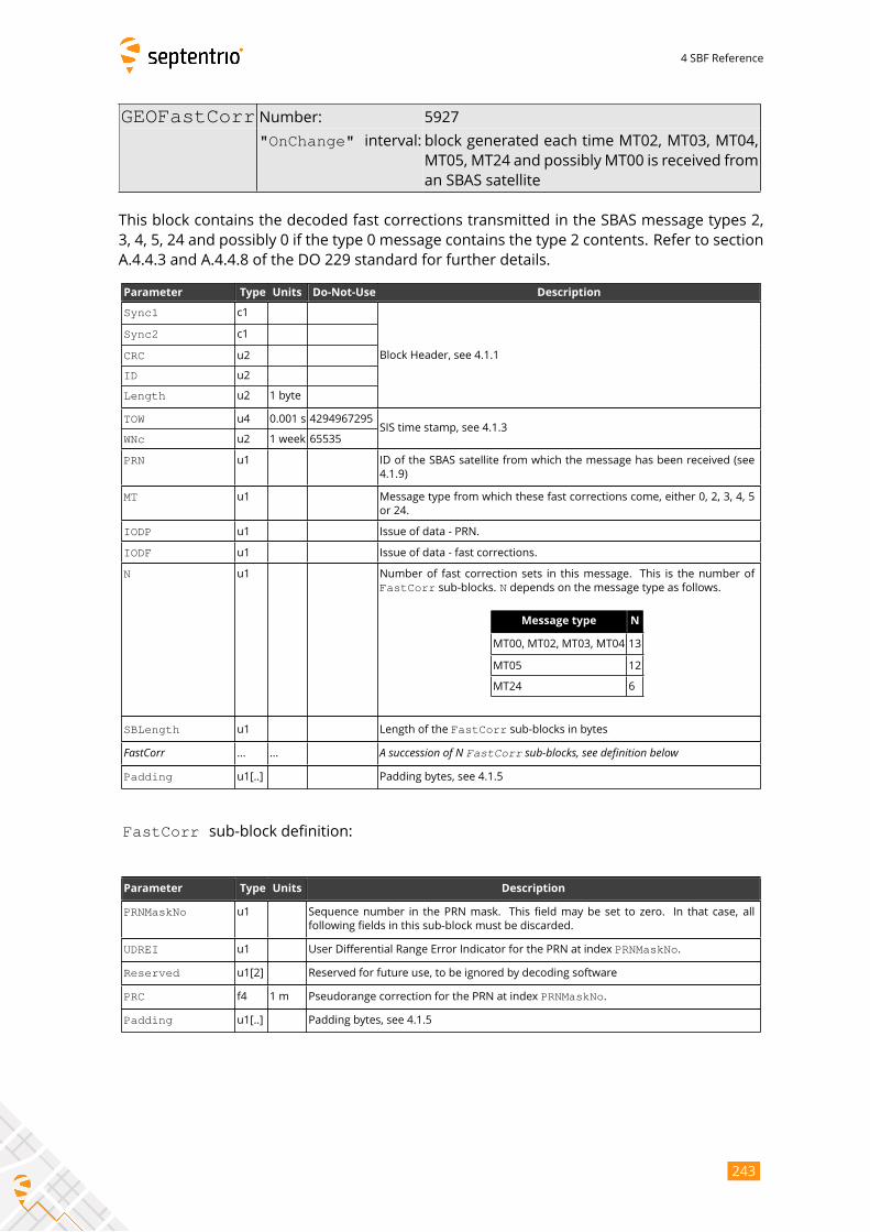
4 SBF Reference
GEOFastCorr Number: 5927
"OnChange" interval: block generated each time MT02, MT03, MT04,MT05, MT24 and possibly MT00 is received from
an SBAS satellite
This block contains the decoded fast corrections transmitted in the SBAS message types 2,
3, 4, 5, 24 and possibly 0 if the type 0 message contains the type 2 contents. Refer to section
A.4.4.3 and A.4.4.8 of the DO 229 standard for further details.
Parameter Type Units Do-Not-Use Description
Sync1 c1
Block Header, see 4.1.1
Sync2 c1
CRC u2
ID u2
Length u2 1 byte
TOW u4 0.001 s 4294967295SIS time stamp, see 4.1.3
WNc u2 1 week 65535
PRN u1 ID of the SBAS satellite from which the message has been received (see
4.1.9)
MT u1 Message type from which these fast corrections come, either 0, 2, 3, 4, 5
or 24.
IODP u1 Issue of data - PRN.
IODF u1 Issue of data - fast corrections.
N u1 Number of fast correction sets in this message. This is the number of
FastCorr sub-blocks. N depends on the message type as follows.
Message type N
MT00, MT02, MT03, MT04 13
MT05 12
MT24 6
SBLength u1 Length of the FastCorr sub-blocks in bytes
FastCorr ... ... A succession of N FastCorr sub-blocks, see definition belowPadding u1[..] Padding bytes, see 4.1.5
FastCorr sub-block definition:
Parameter Type Units Description
PRNMaskNo u1 Sequence number in the PRN mask. This field may be set to zero. In that case, all
following fields in this sub-block must be discarded.
UDREI u1 User Differential Range Error Indicator for the PRN at index PRNMaskNo.
Reserved u1[2] Reserved for future use, to be ignored by decoding software
PRC f4 1 m Pseudorange correction for the PRN at index PRNMaskNo.
Padding u1[..] Padding bytes, see 4.1.5
243
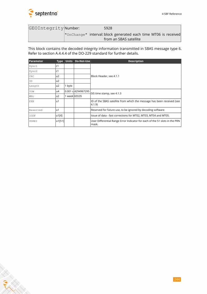
4 SBF Reference
GEOIntegrity Number: 5928
"OnChange" interval: block generated each time MT06 is receivedfrom an SBAS satellite
This block contains the decoded integrity information transmitted in SBAS message type 6.
Refer to section A.4.4.4 of the DO-229 standard for further details.
Parameter Type Units Do-Not-Use Description
Sync1 c1
Block Header, see 4.1.1
Sync2 c1
CRC u2
ID u2
Length u2 1 byte
TOW u4 0.001 s 4294967295SIS time stamp, see 4.1.3
WNc u2 1 week 65535
PRN u1 ID of the SBAS satellite from which the message has been received (see
4.1.9)
Reserved u1 Reserved for future use, to be ignored by decoding software
IODF u1[4] Issue of data - fast corrections for MT02, MT03, MT04 and MT05.
UDREI u1[51] User Differential Range Error Indicator for each of the 51 slots in the PRN
mask.
244
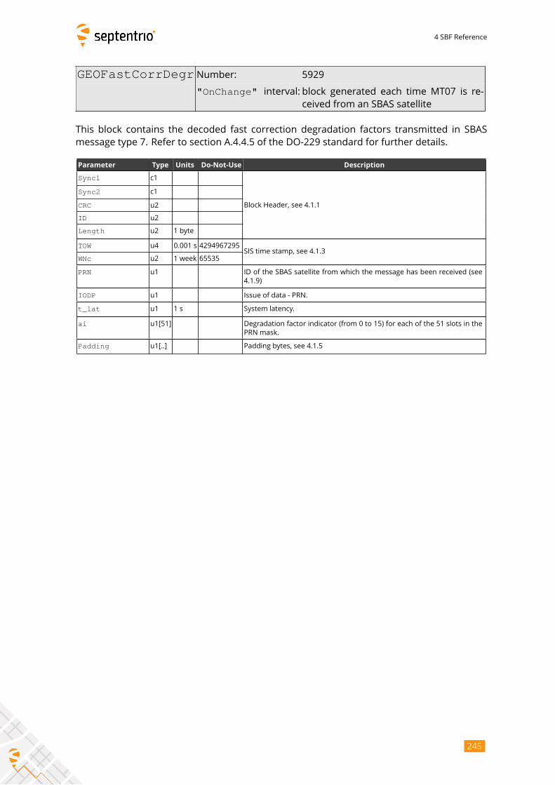
4 SBF Reference
GEOFastCorrDegr Number: 5929
"OnChange" interval: block generated each time MT07 is re-ceived from an SBAS satellite
This block contains the decoded fast correction degradation factors transmitted in SBAS
message type 7. Refer to section A.4.4.5 of the DO-229 standard for further details.
Parameter Type Units Do-Not-Use Description
Sync1 c1
Block Header, see 4.1.1
Sync2 c1
CRC u2
ID u2
Length u2 1 byte
TOW u4 0.001 s 4294967295SIS time stamp, see 4.1.3
WNc u2 1 week 65535
PRN u1 ID of the SBAS satellite from which the message has been received (see
4.1.9)
IODP u1 Issue of data - PRN.
t_lat u1 1 s System latency.
ai u1[51] Degradation factor indicator (from 0 to 15) for each of the 51 slots in the
PRN mask.
Padding u1[..] Padding bytes, see 4.1.5
245
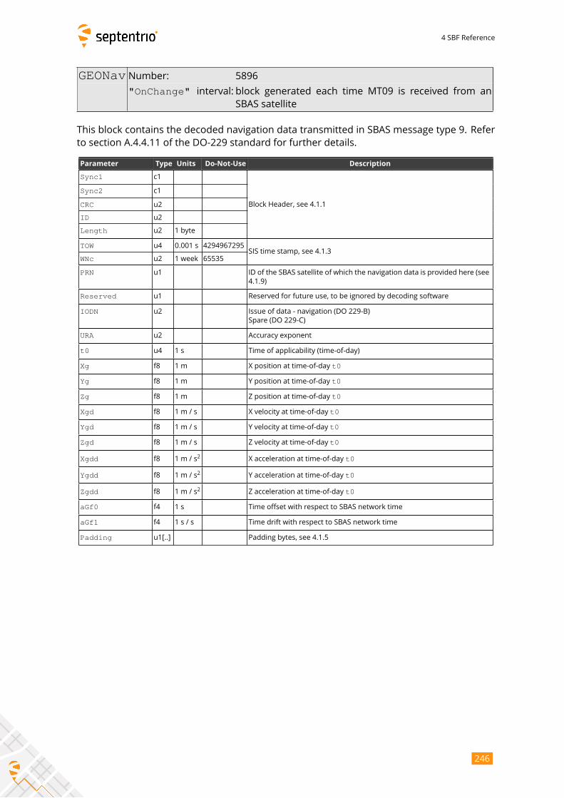
4 SBF Reference
GEONav Number: 5896
"OnChange" interval: block generated each time MT09 is received from an
SBAS satellite
This block contains the decoded navigation data transmitted in SBAS message type 9. Refer
to section A.4.4.11 of the DO-229 standard for further details.
Parameter Type Units Do-Not-Use Description
Sync1 c1
Block Header, see 4.1.1
Sync2 c1
CRC u2
ID u2
Length u2 1 byte
TOW u4 0.001 s 4294967295SIS time stamp, see 4.1.3
WNc u2 1 week 65535
PRN u1 ID of the SBAS satellite of which the navigation data is provided here (see
4.1.9)
Reserved u1 Reserved for future use, to be ignored by decoding software
IODN u2 Issue of data - navigation (DO 229-B)
Spare (DO 229-C)
URA u2 Accuracy exponent
t0 u4 1 s Time of applicability (time-of-day)
Xg f8 1 m X position at time-of-day t0
Yg f8 1 m Y position at time-of-day t0
Zg f8 1 m Z position at time-of-day t0
Xgd f8 1 m / s X velocity at time-of-day t0
Ygd f8 1 m / s Y velocity at time-of-day t0
Zgd f8 1 m / s Z velocity at time-of-day t0
Xgdd f8 1 m / s2
X acceleration at time-of-day t0
Ygdd f8 1 m / s2
Y acceleration at time-of-day t0
Zgdd f8 1 m / s2
Z acceleration at time-of-day t0
aGf0 f4 1 s Time offset with respect to SBAS network time
aGf1 f4 1 s / s Time drift with respect to SBAS network time
Padding u1[..] Padding bytes, see 4.1.5
246
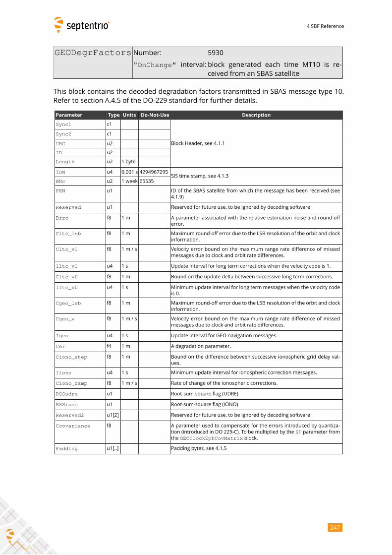
4 SBF Reference
GEODegrFactors Number: 5930
"OnChange" interval: block generated each time MT10 is re-ceived from an SBAS satellite
This block contains the decoded degradation factors transmitted in SBAS message type 10.
Refer to section A.4.5 of the DO-229 standard for further details.
Parameter Type Units Do-Not-Use Description
Sync1 c1
Block Header, see 4.1.1
Sync2 c1
CRC u2
ID u2
Length u2 1 byte
TOW u4 0.001 s 4294967295SIS time stamp, see 4.1.3
WNc u2 1 week 65535
PRN u1 ID of the SBAS satellite from which the message has been received (see
4.1.9)
Reserved u1 Reserved for future use, to be ignored by decoding software
Brrc f8 1 m A parameter associated with the relative estimation noise and round-off
error.
Cltc_lsb f8 1 m Maximum round-off error due to the LSB resolution of the orbit and clock
information.
Cltc_v1 f8 1 m / s Velocity error bound on the maximum range rate difference of missed
messages due to clock and orbit rate differences.
Iltc_v1 u4 1 s Update interval for long term corrections when the velocity code is 1.
Cltc_v0 f8 1 m Bound on the update delta between successive long term corrections.
Iltc_v0 u4 1 s Minimum update interval for long term messages when the velocity code
is 0.
Cgeo_lsb f8 1 m Maximum round-off error due to the LSB resolution of the orbit and clock
information.
Cgeo_v f8 1 m / s Velocity error bound on the maximum range rate difference of missed
messages due to clock and orbit rate differences.
Igeo u4 1 s Update interval for GEO navigation messages.
Cer f4 1 m A degradation parameter.
Ciono_step f8 1 m Bound on the difference between successive ionospheric grid delay val-
ues.
Iiono u4 1 s Minimum update interval for ionospheric correction messages.
Ciono_ramp f8 1 m / s Rate of change of the ionospheric corrections.
RSSudre u1 Root-sum-square flag (UDRE)
RSSiono u1 Root-sum-square flag (IONO)
Reserved2 u1[2] Reserved for future use, to be ignored by decoding software
Ccovariance f8 A parameter used to compensate for the errors introduced by quantiza-
tion (introduced in DO 229-C). To be multiplied by the SF parameter fromthe GEOClockEphCovMatrix block.
Padding u1[..] Padding bytes, see 4.1.5
247
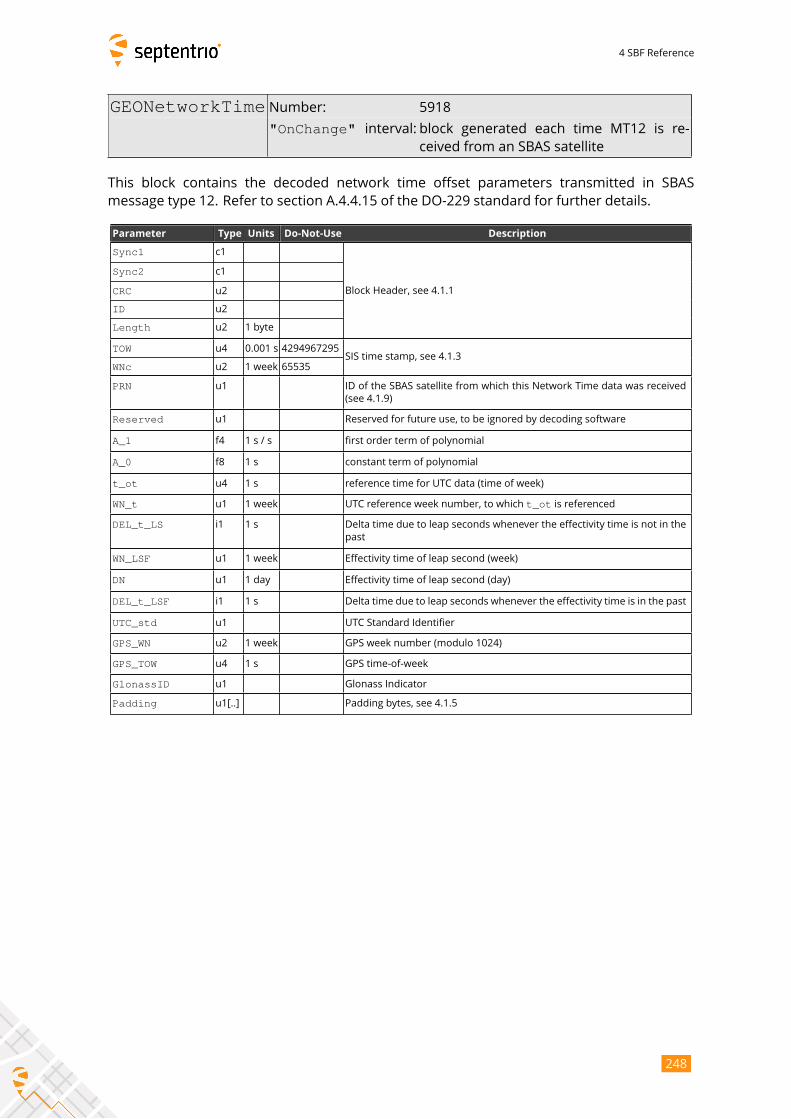
4 SBF Reference
GEONetworkTime Number: 5918
"OnChange" interval: block generated each time MT12 is re-ceived from an SBAS satellite
This block contains the decoded network time offset parameters transmitted in SBAS
message type 12. Refer to section A.4.4.15 of the DO-229 standard for further details.
Parameter Type Units Do-Not-Use Description
Sync1 c1
Block Header, see 4.1.1
Sync2 c1
CRC u2
ID u2
Length u2 1 byte
TOW u4 0.001 s 4294967295SIS time stamp, see 4.1.3
WNc u2 1 week 65535
PRN u1 ID of the SBAS satellite from which this Network Time data was received
(see 4.1.9)
Reserved u1 Reserved for future use, to be ignored by decoding software
A_1 f4 1 s / s first order term of polynomial
A_0 f8 1 s constant term of polynomial
t_ot u4 1 s reference time for UTC data (time of week)
WN_t u1 1 week UTC reference week number, to which t_ot is referenced
DEL_t_LS i1 1 s Delta time due to leap seconds whenever the effectivity time is not in the
past
WN_LSF u1 1 week Effectivity time of leap second (week)
DN u1 1 day Effectivity time of leap second (day)
DEL_t_LSF i1 1 s Delta time due to leap seconds whenever the effectivity time is in the past
UTC_std u1 UTC Standard Identifier
GPS_WN u2 1 week GPS week number (modulo 1024)
GPS_TOW u4 1 s GPS time-of-week
GlonassID u1 Glonass Indicator
Padding u1[..] Padding bytes, see 4.1.5
248
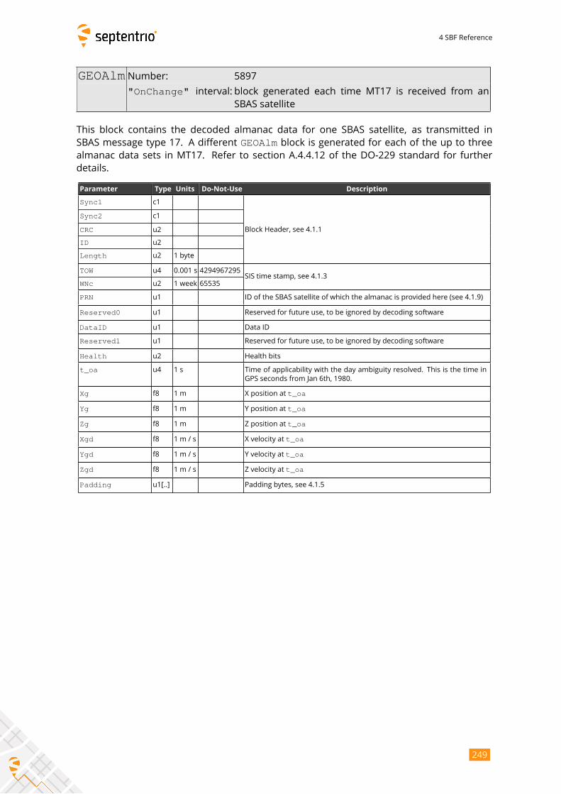
4 SBF Reference
GEOAlm Number: 5897
"OnChange" interval: block generated each time MT17 is received from an
SBAS satellite
This block contains the decoded almanac data for one SBAS satellite, as transmitted in
SBAS message type 17. A different GEOAlm block is generated for each of the up to threealmanac data sets in MT17. Refer to section A.4.4.12 of the DO-229 standard for further
details.
Parameter Type Units Do-Not-Use Description
Sync1 c1
Block Header, see 4.1.1
Sync2 c1
CRC u2
ID u2
Length u2 1 byte
TOW u4 0.001 s 4294967295SIS time stamp, see 4.1.3
WNc u2 1 week 65535
PRN u1 ID of the SBAS satellite of which the almanac is provided here (see 4.1.9)
Reserved0 u1 Reserved for future use, to be ignored by decoding software
DataID u1 Data ID
Reserved1 u1 Reserved for future use, to be ignored by decoding software
Health u2 Health bits
t_oa u4 1 s Time of applicability with the day ambiguity resolved. This is the time in
GPS seconds from Jan 6th, 1980.
Xg f8 1 m X position at t_oa
Yg f8 1 m Y position at t_oa
Zg f8 1 m Z position at t_oa
Xgd f8 1 m / s X velocity at t_oa
Ygd f8 1 m / s Y velocity at t_oa
Zgd f8 1 m / s Z velocity at t_oa
Padding u1[..] Padding bytes, see 4.1.5
249
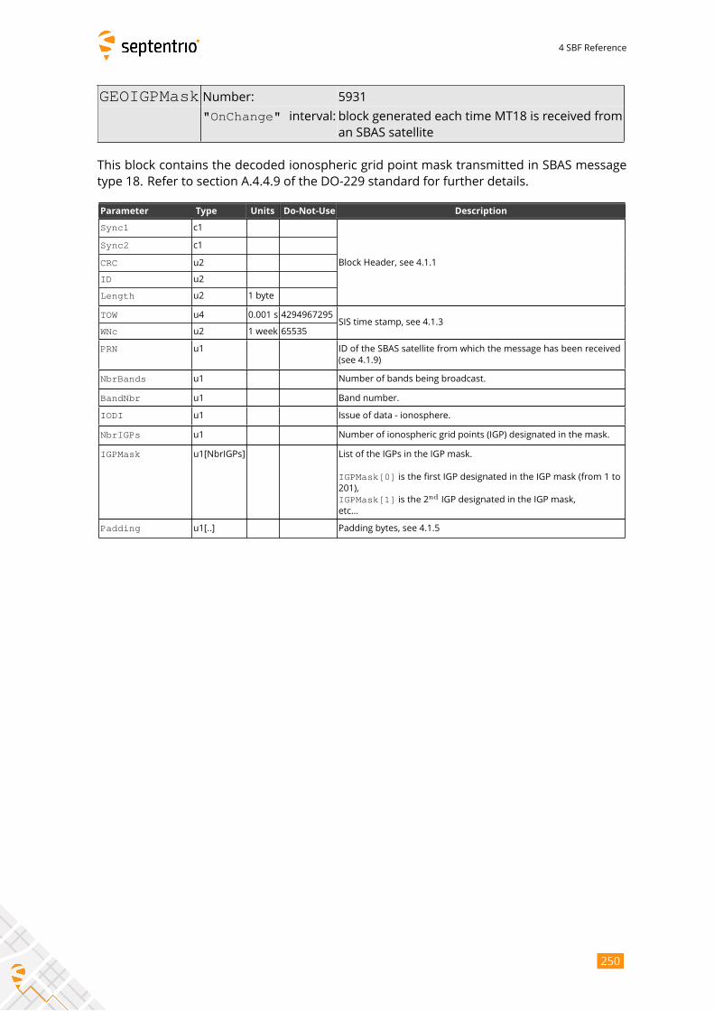
4 SBF Reference
GEOIGPMask Number: 5931
"OnChange" interval: block generated each time MT18 is received froman SBAS satellite
This block contains the decoded ionospheric grid point mask transmitted in SBAS message
type 18. Refer to section A.4.4.9 of the DO-229 standard for further details.
Parameter Type Units Do-Not-Use Description
Sync1 c1
Block Header, see 4.1.1
Sync2 c1
CRC u2
ID u2
Length u2 1 byte
TOW u4 0.001 s 4294967295SIS time stamp, see 4.1.3
WNc u2 1 week 65535
PRN u1 ID of the SBAS satellite from which the message has been received
(see 4.1.9)
NbrBands u1 Number of bands being broadcast.
BandNbr u1 Band number.
IODI u1 Issue of data - ionosphere.
NbrIGPs u1 Number of ionospheric grid points (IGP) designated in the mask.
IGPMask u1[NbrIGPs] List of the IGPs in the IGP mask.
IGPMask[0] is the first IGP designated in the IGP mask (from 1 to201),
IGPMask[1] is the 2ndIGP designated in the IGP mask,
etc...
Padding u1[..] Padding bytes, see 4.1.5
250
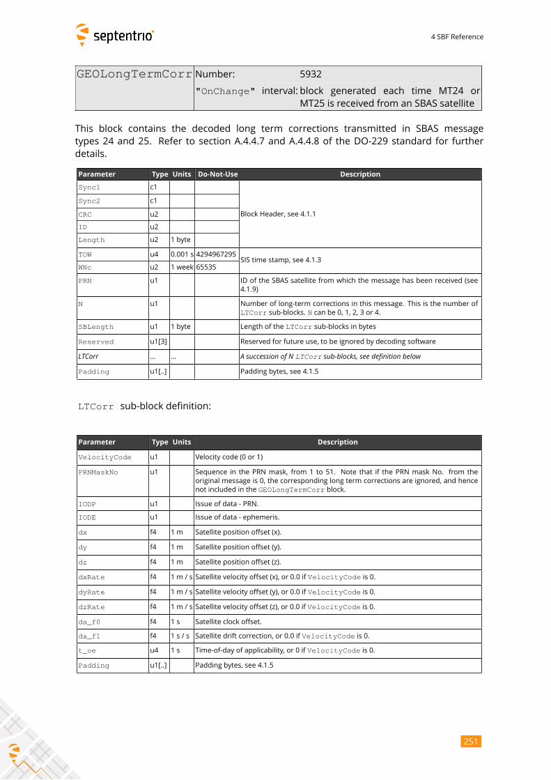
4 SBF Reference
GEOLongTermCorr Number: 5932
"OnChange" interval: block generated each time MT24 orMT25 is received from an SBAS satellite
This block contains the decoded long term corrections transmitted in SBAS message
types 24 and 25. Refer to section A.4.4.7 and A.4.4.8 of the DO-229 standard for further
details.
Parameter Type Units Do-Not-Use Description
Sync1 c1
Block Header, see 4.1.1
Sync2 c1
CRC u2
ID u2
Length u2 1 byte
TOW u4 0.001 s 4294967295SIS time stamp, see 4.1.3
WNc u2 1 week 65535
PRN u1 ID of the SBAS satellite from which the message has been received (see
4.1.9)
N u1 Number of long-term corrections in this message. This is the number of
LTCorr sub-blocks. N can be 0, 1, 2, 3 or 4.
SBLength u1 1 byte Length of the LTCorr sub-blocks in bytes
Reserved u1[3] Reserved for future use, to be ignored by decoding software
LTCorr ... ... A succession of N LTCorr sub-blocks, see definition belowPadding u1[..] Padding bytes, see 4.1.5
LTCorr sub-block definition:
Parameter Type Units Description
VelocityCode u1 Velocity code (0 or 1)
PRNMaskNo u1 Sequence in the PRN mask, from 1 to 51. Note that if the PRN mask No. from the
original message is 0, the corresponding long term corrections are ignored, and hence
not included in the GEOLongTermCorr block.
IODP u1 Issue of data - PRN.
IODE u1 Issue of data - ephemeris.
dx f4 1 m Satellite position offset (x).
dy f4 1 m Satellite position offset (y).
dz f4 1 m Satellite position offset (z).
dxRate f4 1 m / s Satellite velocity offset (x), or 0.0 if VelocityCode is 0.
dyRate f4 1 m / s Satellite velocity offset (y), or 0.0 if VelocityCode is 0.
dzRate f4 1 m / s Satellite velocity offset (z), or 0.0 if VelocityCode is 0.
da_f0 f4 1 s Satellite clock offset.
da_f1 f4 1 s / s Satellite drift correction, or 0.0 if VelocityCode is 0.
t_oe u4 1 s Time-of-day of applicability, or 0 if VelocityCode is 0.
Padding u1[..] Padding bytes, see 4.1.5
251
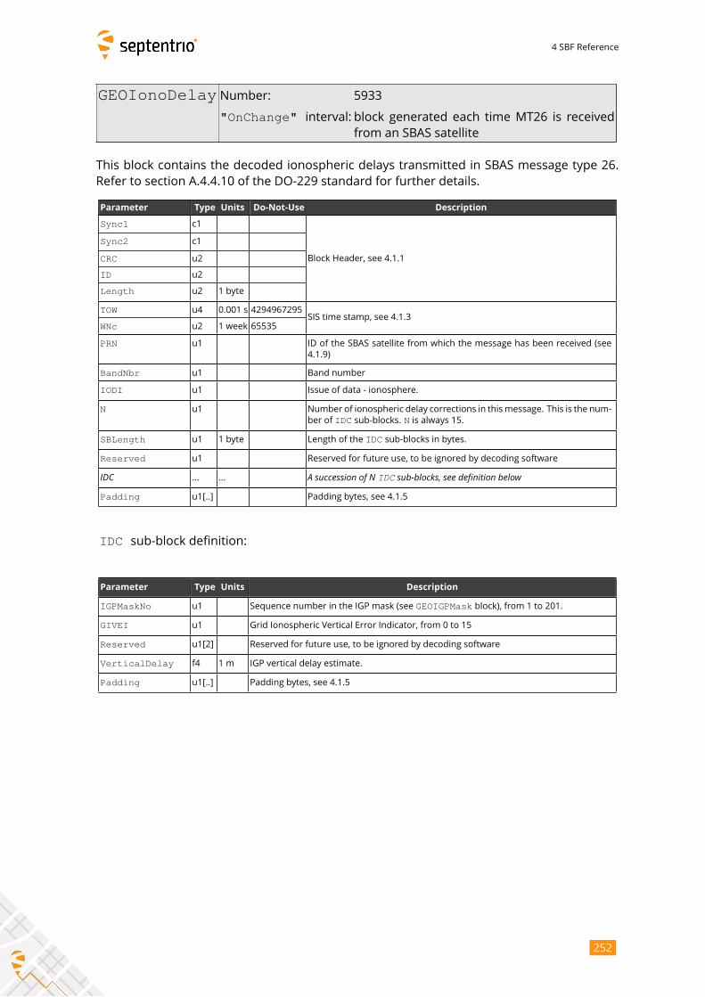
4 SBF Reference
GEOIonoDelay Number: 5933
"OnChange" interval: block generated each time MT26 is receivedfrom an SBAS satellite
This block contains the decoded ionospheric delays transmitted in SBAS message type 26.
Refer to section A.4.4.10 of the DO-229 standard for further details.
Parameter Type Units Do-Not-Use Description
Sync1 c1
Block Header, see 4.1.1
Sync2 c1
CRC u2
ID u2
Length u2 1 byte
TOW u4 0.001 s 4294967295SIS time stamp, see 4.1.3
WNc u2 1 week 65535
PRN u1 ID of the SBAS satellite from which the message has been received (see
4.1.9)
BandNbr u1 Band number
IODI u1 Issue of data - ionosphere.
N u1 Number of ionospheric delay corrections in thismessage. This is the num-
ber of IDC sub-blocks. N is always 15.
SBLength u1 1 byte Length of the IDC sub-blocks in bytes.
Reserved u1 Reserved for future use, to be ignored by decoding software
IDC ... ... A succession of N IDC sub-blocks, see definition belowPadding u1[..] Padding bytes, see 4.1.5
IDC sub-block definition:
Parameter Type Units Description
IGPMaskNo u1 Sequence number in the IGP mask (see GEOIGPMask block), from 1 to 201.
GIVEI u1 Grid Ionospheric Vertical Error Indicator, from 0 to 15
Reserved u1[2] Reserved for future use, to be ignored by decoding software
VerticalDelay f4 1 m IGP vertical delay estimate.
Padding u1[..] Padding bytes, see 4.1.5
252
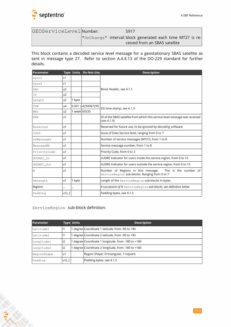
4 SBF Reference
GEOServiceLevel Number: 5917
"OnChange" interval: block generated each time MT27 is re-ceived from an SBAS satellite
This block contains a decoded service level message for a geostationary SBAS satellite as
sent in message type 27. Refer to section A.4.4.13 of the DO-229 standard for further
details.
Parameter Type Units Do-Not-Use Description
Sync1 c1
Block Header, see 4.1.1
Sync2 c1
CRC u2
ID u2
Length u2 1 byte
TOW u4 0.001 s 4294967295SIS time stamp, see 4.1.3
WNc u2 1 week 65535
PRN u1 ID of the SBAS satellite fromwhich this service level message was received
(see 4.1.9)
Reserved u1 Reserved for future use, to be ignored by decoding software
IODS u1 Issue of Data Service level, ranging from 0 to 7
nrMessages u1 Number of service messages (MT27), from 1 to 8
MessageNR u1 Service message number, from 1 to 8
PriorityCode u1 Priority Code, from 0 to 3
dUDREI_In u1 δUDRE Indicator for users inside the service region, from 0 to 15
dUDREI_Out u1 δUDRE Indicator for users outside the service region, from 0 to 15
N u1 Number of Regions in this message. This is the number of
ServiceRegion sub-blocks. Ranging from 0 to 7
SBLength u1 1 byte Length of the ServiceRegion sub-blocks in bytes
Regions ... ... A succession of N ServiceRegion sub-blocks, see definition belowPadding u1[..] Padding bytes, see 4.1.5
ServiceRegion sub-block definition:
Parameter Type Units Description
Latitude1 i1 1 degree Coordinate 1 latitude, from -90 to +90
Latitude2 i1 1 degree Coordinate 2 latitude, from -90 to +90
Longitude1 i2 1 degree Coordinate 1 longitude, from -180 to +180
Longitude2 i2 1 degree Coordinate 2 longitude, from -180 to +180
RegionShape u1 Region Shape: 0=triangular, 1=square
Padding u1[..] Padding bytes, see 4.1.5
253
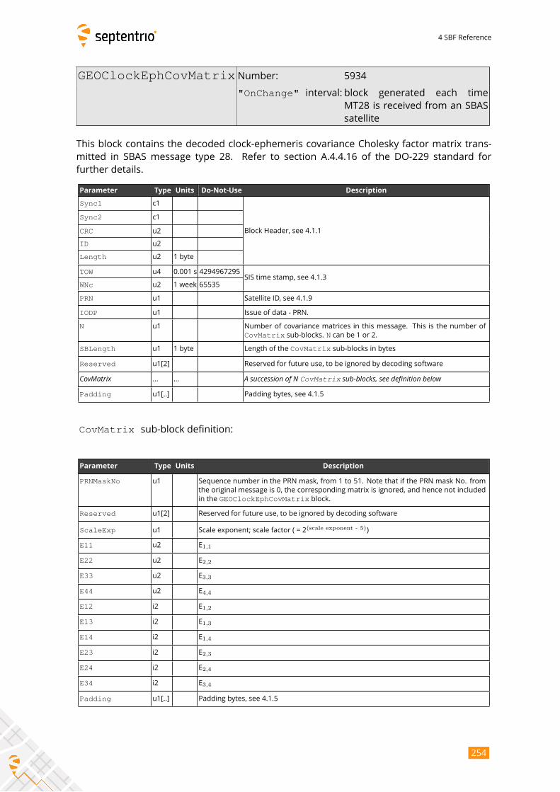
4 SBF Reference
GEOClockEphCovMatrix Number: 5934
"OnChange" interval: block generated each time
MT28 is received from an SBAS
satellite
This block contains the decoded clock-ephemeris covariance Cholesky factor matrix trans-
mitted in SBAS message type 28. Refer to section A.4.4.16 of the DO-229 standard for
further details.
Parameter Type Units Do-Not-Use Description
Sync1 c1
Block Header, see 4.1.1
Sync2 c1
CRC u2
ID u2
Length u2 1 byte
TOW u4 0.001 s 4294967295SIS time stamp, see 4.1.3
WNc u2 1 week 65535
PRN u1 Satellite ID, see 4.1.9
IODP u1 Issue of data - PRN.
N u1 Number of covariance matrices in this message. This is the number of
CovMatrix sub-blocks. N can be 1 or 2.
SBLength u1 1 byte Length of the CovMatrix sub-blocks in bytes
Reserved u1[2] Reserved for future use, to be ignored by decoding software
CovMatrix ... ... A succession of N CovMatrix sub-blocks, see definition belowPadding u1[..] Padding bytes, see 4.1.5
CovMatrix sub-block definition:
Parameter Type Units Description
PRNMaskNo u1 Sequence number in the PRN mask, from 1 to 51. Note that if the PRN mask No. from
the original message is 0, the corresponding matrix is ignored, and hence not included
in the GEOClockEphCovMatrix block.
Reserved u1[2] Reserved for future use, to be ignored by decoding software
ScaleExp u1 Scale exponent; scale factor ( = 2(scale exponent - 5)
)
E11 u2 E1,1
E22 u2 E2,2
E33 u2 E3,3
E44 u2 E4,4
E12 i2 E1,2
E13 i2 E1,3
E14 i2 E1,4
E23 i2 E2,3
E24 i2 E2,4
E34 i2 E3,4
Padding u1[..] Padding bytes, see 4.1.5
254
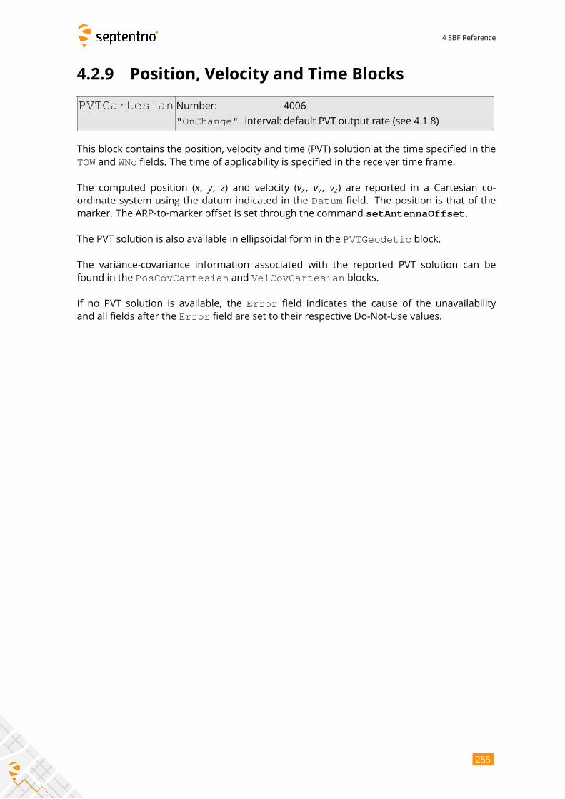
4 SBF Reference
4.2.9 Position, Velocity and Time Blocks
PVTCartesian Number: 4006
"OnChange" interval: default PVT output rate (see 4.1.8)
This block contains the position, velocity and time (PVT) solution at the time specified in the
TOW and WNc fields. The time of applicability is specified in the receiver time frame.
The computed position (x, y, z) and velocity (vx, vy , vz) are reported in a Cartesian co-ordinate system using the datum indicated in the Datum field. The position is that of the
marker. The ARP-to-marker offset is set through the command setAntennaOffset.
The PVT solution is also available in ellipsoidal form in the PVTGeodetic block.
The variance-covariance information associated with the reported PVT solution can be
found in the PosCovCartesian and VelCovCartesian blocks.
If no PVT solution is available, the Error field indicates the cause of the unavailability
and all fields after the Error field are set to their respective Do-Not-Use values.
255
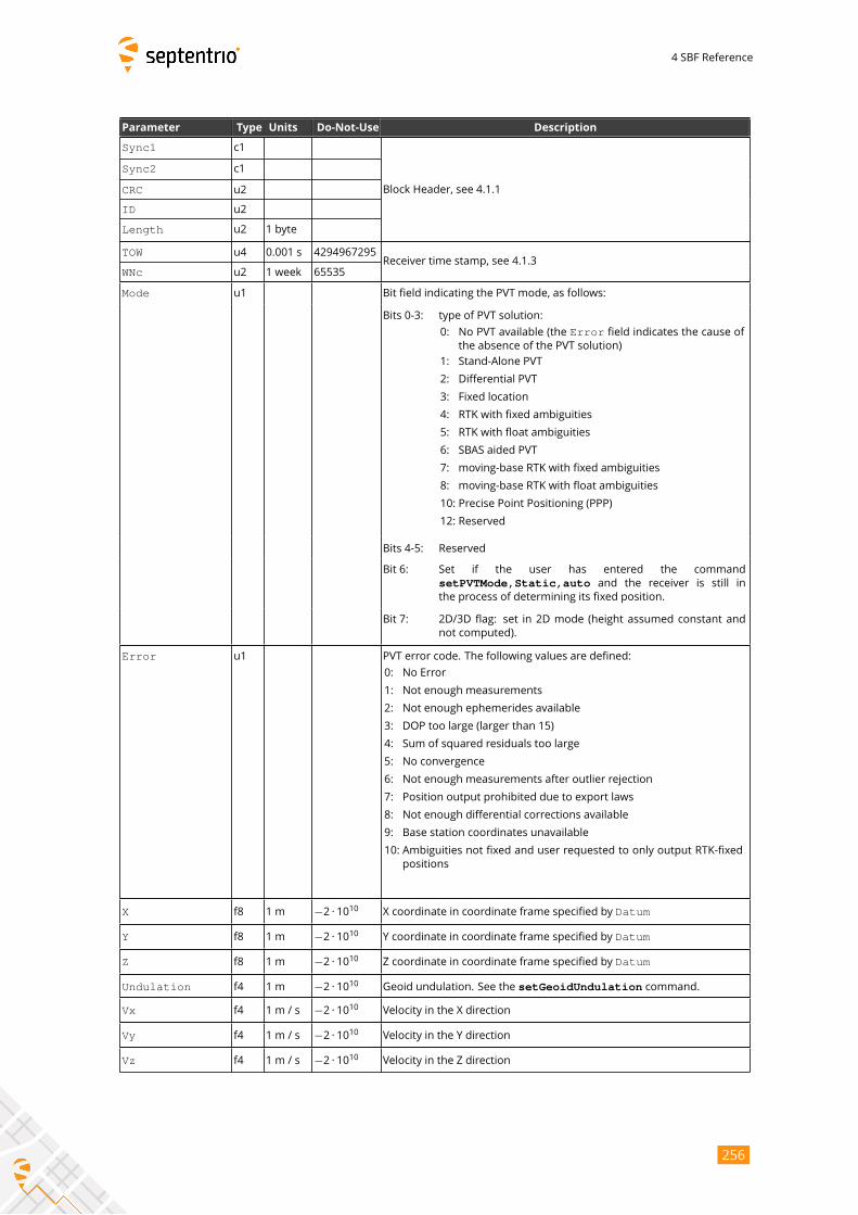
4 SBF Reference
Parameter Type Units Do-Not-Use Description
Sync1 c1
Block Header, see 4.1.1
Sync2 c1
CRC u2
ID u2
Length u2 1 byte
TOW u4 0.001 s 4294967295Receiver time stamp, see 4.1.3
WNc u2 1 week 65535
Mode u1 Bit field indicating the PVT mode, as follows:
Bits 0-3: type of PVT solution:
0: No PVT available (the Error field indicates the cause of
the absence of the PVT solution)
1: Stand-Alone PVT
2: Differential PVT
3: Fixed location
4: RTK with fixed ambiguities
5: RTK with float ambiguities
6: SBAS aided PVT
7: moving-base RTK with fixed ambiguities
8: moving-base RTK with float ambiguities
10: Precise Point Positioning (PPP)
12: Reserved
Bits 4-5: Reserved
Bit 6: Set if the user has entered the command
setPVTMode,Static,auto and the receiver is still in
the process of determining its fixed position.
Bit 7: 2D/3D flag: set in 2D mode (height assumed constant and
not computed).
Error u1 PVT error code. The following values are defined:
0: No Error
1: Not enough measurements
2: Not enough ephemerides available
3: DOP too large (larger than 15)
4: Sum of squared residuals too large
5: No convergence
6: Not enough measurements after outlier rejection
7: Position output prohibited due to export laws
8: Not enough differential corrections available
9: Base station coordinates unavailable
10: Ambiguities not fixed and user requested to only output RTK-fixed
positions
X f8 1 m −2 · 1010 X coordinate in coordinate frame specified by Datum
Y f8 1 m −2 · 1010 Y coordinate in coordinate frame specified by Datum
Z f8 1 m −2 · 1010 Z coordinate in coordinate frame specified by Datum
Undulation f4 1 m −2 · 1010 Geoid undulation. See the setGeoidUndulation command.
Vx f4 1 m / s −2 · 1010 Velocity in the X direction
Vy f4 1 m / s −2 · 1010 Velocity in the Y direction
Vz f4 1 m / s −2 · 1010 Velocity in the Z direction
256
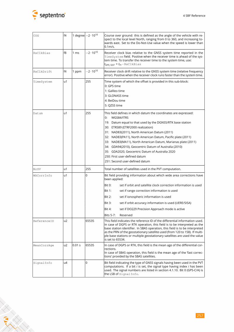
4 SBF Reference
COG f4 1 degree −2 · 1010 Course over ground: this is defined as the angle of the vehicle with re-
spect to the local level North, ranging from 0 to 360, and increasing to-
wards east. Set to the Do-Not-Use value when the speed is lower than
0.1m/s.
RxClkBias f8 1 ms −2 · 1010 Receiver clock bias relative to the GNSS system time reported in the
TimeSystem field. Positive when the receiver time is ahead of the sys-tem time. To transfer the receiver time to the system time, use:tGPS/GST = trx - RxClkBias
RxClkDrift f4 1 ppm −2 · 1010 Receiver clock drift relative to the GNSS system time (relative frequency
error). Positive when the receiver clock runs faster than the system time.
TimeSystem u1 255 Time system of which the offset is provided in this sub-block:
0: GPS time
1: Galileo time
3: GLONASS time
4: BeiDou time
5: QZSS time
Datum u1 255 This field defines in which datum the coordinates are expressed:
0: WGS84/ITRS
19: Datum equal to that used by the DGNSS/RTK base station
30: ETRS89 (ETRF2000 realization)
31: NAD83(2011), North American Datum (2011)
32: NAD83(PA11), North American Datum, Pacific plate (2011)
33: NAD83(MA11), North American Datum, Marianas plate (2011)
34: GDA94(2010), Geocentric Datum of Australia (2010)
35: GDA2020, Geocentric Datum of Australia 2020
250: First user-defined datum
251: Second user-defined datum
NrSV u1 255 Total number of satellites used in the PVT computation.
WACorrInfo u1 0 Bit field providing information about which wide area corrections have
been applied:
Bit 0: set if orbit and satellite clock correction information is used
Bit 1: set if range correction information is used
Bit 2: set if ionospheric information is used
Bit 3: set if orbit accuracy information is used (UERE/SISA)
Bit 4: set if DO229 Precision Approach mode is active
Bits 5-7: Reserved
ReferenceID u2 65535 This field indicates the reference ID of the differential information used.
In case of DGPS or RTK operation, this field is to be interpreted as the
base station identifier. In SBAS operation, this field is to be interpreted
as the PRN of the geostationary satellite used (from 120 to 158). If multi-
ple base stations or multiple geostationary satellites are used the value
is set to 65534.
MeanCorrAge u2 0.01 s 65535 In case of DGPS or RTK, this field is the mean age of the differential cor-
rections.
In case of SBAS operation, this field is the mean age of the ’fast correc-
tions’ provided by the SBAS satellites.
SignalInfo u4 0 Bit field indicating the type of GNSS signals having been used in the PVT
computations. If a bit i is set, the signal type having index i has beenused. The signal numbers are listed in section 4.1.10. Bit 0 (GPS-C/A) is
the LSB of SignalInfo.
257

4 SBF Reference
AlertFlag u1 0 Bit field indicating integrity related information:
Bits 0-1: RAIM integrity flag:
0: RAIM not active (integrity not monitored)
1: RAIM integrity test successful
2: RAIM integrity test failed
3: Reserved
Bit 2: set if integrity has failed as per Galileo HPCA (HMI Probability
Computation Algorithm)
Bit 3: set if Galileo ionospheric storm flag is active
Bit 4: Reserved
Bits 5-7: Reserved
NrBases u1 0 Number of base stations used in the PVT computation.
PPPInfo u2 0 Bit field containing PPP-related information:
1 s Bits 0-11: Age of the last seed, in seconds. The age is clipped to 4091s.
This field must be ignored when the seed type is 0 (see bits
13-15 below).
Bit 12: Reserved
Bits 13-15: Type of last seed:
0: Not seeded or not in PPP positioning mode
1: Manual seed
2: Seeded from DGPS
3: Seeded from RTKFixed
Rev 1
Latency u2 0.0001 s 65535 Time elapsed between the time of applicability of the position fix and
the generation of this SBF block by the receiver. This time includes the
receiver processing time, but not the communication latency.
HAccuracy u2 0.01 m 65535 2DRMS horizontal accuracy: twice the root-mean-square of the horizon-
tal distance error. The horizontal distance between the true position
and the computed position is expected to be lower than HAccuracywith a probability of at least 95%. The value is clipped to 65534
=655.34m
VAccuracy u2 0.01 m 65535 2-sigma vertical accuracy. The vertical distance between the true
position and the computed position is expected to be lower than
VAccuracy with a probability of at least 95%. The value is clipped to65534 =655.34m.
Misc u1 Bit field containing miscellaneous flags:
Bit 0: In DGNSS or RTK mode, set if the baseline points to the base
station ARP. Unset if it points to the antenna phase center, or
if unknown.
Bit 1: Set if the phase center offset is compensated for at the rover,
unset if not or unknown.
Bit 2: Proprietary.
Bit 3: Proprietary.
Bits 4-5: Proprietary.
Bits 6-7: Flag indicating whether the marker position reported in this
block is also the ARP position (i.e. whether the ARP-to-
marker offset provided with the setAntennaOffset com-mand is zero or not)
0: Unknown
1: The ARP-to-marker offset is zero
2: The ARP-to-marker offset is not zero
Rev 2
Padding u1[..] Padding bytes, see 4.1.5
258
4 SBF Reference
PVTGeodetic Number: 4007
"OnChange" interval: default PVT output rate (see 4.1.8)
This block contains the position, velocity and time (PVT) solution at the time specified in the
TOW and WNc fields. The time of applicability is specified in the receiver time frame.
The computed position (ϕ,λ,h) and velocity (vn, ve, vu) are reported in an ellipsoidal co-ordinate system using the datum indicated in the Datum field. The velocity vector is
expressed relative to the local-level Cartesian coordinate frame with north-, east-, up-unit
vectors. The position is that of the marker. The ARP-to-marker offset is set through the
command setAntennaOffset.
The PVT solution is also available in Cartesian form in the PVTCartesian block.
The variance-covariance information associated with the reported PVT solution can be
found in the PosCovGeodetic and VelCovGeodetic blocks.
If no PVT solution is available, the Error field indicates the cause of the unavailability
and all fields after the Error field are set to their respective Do-Not-Use values.
259

4 SBF Reference
Parameter Type Units Do-Not-Use Description
Sync1 c1
Block Header, see 4.1.1
Sync2 c1
CRC u2
ID u2
Length u2 1 byte
TOW u4 0.001 s 4294967295Receiver time stamp, see 4.1.3
WNc u2 1 week 65535
Mode u1 Bit field indicating the PVT mode, as follows:
Bits 0-3: type of PVT solution:
0: No PVT available (the Error field indicates the cause of
the absence of the PVT solution)
1: Stand-Alone PVT
2: Differential PVT
3: Fixed location
4: RTK with fixed ambiguities
5: RTK with float ambiguities
6: SBAS aided PVT
7: moving-base RTK with fixed ambiguities
8: moving-base RTK with float ambiguities
10: Precise Point Positioning (PPP)
12: Reserved
Bits 4-5: Reserved
Bit 6: Set if the user has entered the command
setPVTMode,Static,auto and the receiver is still in
the process of determining its fixed position.
Bit 7: 2D/3D flag: set in 2D mode (height assumed constant and
not computed).
Error u1 PVT error code. The following values are defined:
0: No Error
1: Not enough measurements
2: Not enough ephemerides available
3: DOP too large (larger than 15)
4: Sum of squared residuals too large
5: No convergence
6: Not enough measurements after outlier rejection
7: Position output prohibited due to export laws
8: Not enough differential corrections available
9: Base station coordinates unavailable
10: Ambiguities not fixed and user requested to only output RTK-fixed
positions
Latitude f8 1 rad −2 · 1010 Latitude, from−π/2 to +π/2, positive North of Equator
Longitude f8 1 rad −2 · 1010 Longitude, from−π to +π, positive East of Greenwich
Height f8 1 m −2 · 1010 Ellipsoidal height (with respect to the ellipsoid specified by Datum)
Undulation f4 1 m −2 · 1010 Geoid undulation. See the setGeoidUndulation command.
Vn f4 1 m / s −2 · 1010 Velocity in the North direction
Ve f4 1 m / s −2 · 1010 Velocity in the East direction
Vu f4 1 m / s −2 · 1010 Velocity in the ’Up’ direction
260

4 SBF Reference
COG f4 1 degree −2 · 1010 Course over ground: this is defined as the angle of the vehicle with re-
spect to the local level North, ranging from 0 to 360, and increasing to-
wards east. Set to the Do-Not-Use value when the speed is lower than
0.1m/s.
RxClkBias f8 1 ms −2 · 1010 Receiver clock bias relative to the GNSS system time reported in the
TimeSystem field. Positive when the receiver time is ahead of the sys-tem time. To transfer the receiver time to the system time, use:tGPS/GST = trx - RxClkBias
RxClkDrift f4 1 ppm −2 · 1010 Receiver clock drift relative to the GNSS system time (relative frequency
error). Positive when the receiver clock runs faster than the system time.
TimeSystem u1 255 Time system of which the offset is provided in this sub-block:
0: GPS time
1: Galileo time
3: GLONASS time
4: BeiDou time
5: QZSS time
Datum u1 255 This field defines in which datum the coordinates are expressed:
0: WGS84/ITRS
19: Datum equal to that used by the DGNSS/RTK base station
30: ETRS89 (ETRF2000 realization)
31: NAD83(2011), North American Datum (2011)
32: NAD83(PA11), North American Datum, Pacific plate (2011)
33: NAD83(MA11), North American Datum, Marianas plate (2011)
34: GDA94(2010), Geocentric Datum of Australia (2010)
35: GDA2020, Geocentric Datum of Australia 2020
250: First user-defined datum
251: Second user-defined datum
NrSV u1 255 Total number of satellites used in the PVT computation.
WACorrInfo u1 0 Bit field providing information about which wide area corrections have
been applied:
Bit 0: set if orbit and satellite clock correction information is used
Bit 1: set if range correction information is used
Bit 2: set if ionospheric information is used
Bit 3: set if orbit accuracy information is used (UERE/SISA)
Bit 4: set if DO229 Precision Approach mode is active
Bits 5-7: Reserved
ReferenceID u2 65535 This field indicates the reference ID of the differential information used.
In case of DGPS or RTK operation, this field is to be interpreted as the
base station identifier. In SBAS operation, this field is to be interpreted
as the PRN of the geostationary satellite used (from 120 to 158). If multi-
ple base stations or multiple geostationary satellites are used the value
is set to 65534.
MeanCorrAge u2 0.01 s 65535 In case of DGPS or RTK, this field is the mean age of the differential cor-
rections.
In case of SBAS operation, this field is the mean age of the ’fast correc-
tions’ provided by the SBAS satellites.
SignalInfo u4 0 Bit field indicating the type of GNSS signals having been used in the PVT
computations. If a bit i is set, the signal type having index i has beenused. The signal numbers are listed in section 4.1.10. Bit 0 (GPS-C/A) is
the LSB of SignalInfo.
261
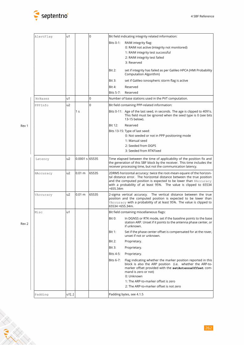
4 SBF Reference
AlertFlag u1 0 Bit field indicating integrity related information:
Bits 0-1: RAIM integrity flag:
0: RAIM not active (integrity not monitored)
1: RAIM integrity test successful
2: RAIM integrity test failed
3: Reserved
Bit 2: set if integrity has failed as per Galileo HPCA (HMI Probability
Computation Algorithm)
Bit 3: set if Galileo ionospheric storm flag is active
Bit 4: Reserved
Bits 5-7: Reserved
NrBases u1 0 Number of base stations used in the PVT computation.
PPPInfo u2 0 Bit field containing PPP-related information:
1 s Bits 0-11: Age of the last seed, in seconds. The age is clipped to 4091s.
This field must be ignored when the seed type is 0 (see bits
13-15 below).
Bit 12: Reserved
Bits 13-15: Type of last seed:
0: Not seeded or not in PPP positioning mode
1: Manual seed
2: Seeded from DGPS
3: Seeded from RTKFixed
Rev 1
Latency u2 0.0001 s 65535 Time elapsed between the time of applicability of the position fix and
the generation of this SBF block by the receiver. This time includes the
receiver processing time, but not the communication latency.
HAccuracy u2 0.01 m 65535 2DRMS horizontal accuracy: twice the root-mean-square of the horizon-
tal distance error. The horizontal distance between the true position
and the computed position is expected to be lower than HAccuracywith a probability of at least 95%. The value is clipped to 65534
=655.34m
VAccuracy u2 0.01 m 65535 2-sigma vertical accuracy. The vertical distance between the true
position and the computed position is expected to be lower than
VAccuracy with a probability of at least 95%. The value is clipped to65534 =655.34m.
Misc u1 Bit field containing miscellaneous flags:
Bit 0: In DGNSS or RTK mode, set if the baseline points to the base
station ARP. Unset if it points to the antenna phase center, or
if unknown.
Bit 1: Set if the phase center offset is compensated for at the rover,
unset if not or unknown.
Bit 2: Proprietary.
Bit 3: Proprietary.
Bits 4-5: Proprietary.
Bits 6-7: Flag indicating whether the marker position reported in this
block is also the ARP position (i.e. whether the ARP-to-
marker offset provided with the setAntennaOffset com-mand is zero or not)
0: Unknown
1: The ARP-to-marker offset is zero
2: The ARP-to-marker offset is not zero
Rev 2
Padding u1[..] Padding bytes, see 4.1.5
262

4 SBF Reference
PosCovCartesian Number: 5905
"OnChange" interval: default PVT output rate (see 4.1.8)
This block contains the elements of the symmetric variance-covariance matrix of the
position expressed relative to the Cartesian axes of the coordinate system datum requested
by the user: σ2x σxy σxz σxbσyx σ2y σyz σybσzx σzy σ2z σzbσbx σby σbz σ2b
This variance-covariance matrix contains an indication of the accuracy of the estimated
parameters (see diagonal elements) and the correlation between these estimates (see
off-diagonal elements). Note that the variances and covariances are estimated: they are not
necessarily indicative of the actual scatter of the position estimates at a given site.
The position variance results from the propagation of all pseudorange variances using
the observation geometry. The receiver implements a stochastic error model for individual
measurements, based on parameters such as the C/N0, the satellite elevation, the pseudor-
ange type, the URA of the broadcast ephemeris and the ionospheric model.
If the ellipsoidal height is not estimated (2D-mode), all components of the variance-
covariance matrix are undefined and set to their Do-Not-Use value.
263
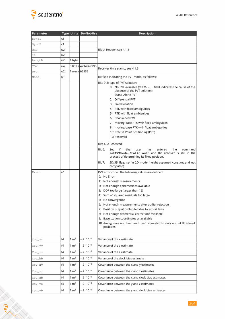
4 SBF Reference
Parameter Type Units Do-Not-Use Description
Sync1 c1
Block Header, see 4.1.1
Sync2 c1
CRC u2
ID u2
Length u2 1 byte
TOW u4 0.001 s 4294967295Receiver time stamp, see 4.1.3
WNc u2 1 week 65535
Mode u1 Bit field indicating the PVT mode, as follows:
Bits 0-3: type of PVT solution:
0: No PVT available (the Error field indicates the cause of the
absence of the PVT solution)
1: Stand-Alone PVT
2: Differential PVT
3: Fixed location
4: RTK with fixed ambiguities
5: RTK with float ambiguities
6: SBAS aided PVT
7: moving-base RTK with fixed ambiguities
8: moving-base RTK with float ambiguities
10: Precise Point Positioning (PPP)
12: Reserved
Bits 4-5: Reserved
Bit 6: Set if the user has entered the command
setPVTMode,Static,auto and the receiver is still in theprocess of determining its fixed position.
Bit 7: 2D/3D flag: set in 2D mode (height assumed constant and not
computed).
Error u1 PVT error code. The following values are defined:
0: No Error
1: Not enough measurements
2: Not enough ephemerides available
3: DOP too large (larger than 15)
4: Sum of squared residuals too large
5: No convergence
6: Not enough measurements after outlier rejection
7: Position output prohibited due to export laws
8: Not enough differential corrections available
9: Base station coordinates unavailable
10: Ambiguities not fixed and user requested to only output RTK-fixed
positions
Cov_xx f4 1 m2 −2 · 1010 Variance of the x estimate
Cov_yy f4 1 m2 −2 · 1010 Variance of the y estimate
Cov_zz f4 1 m2 −2 · 1010 Variance of the z estimate
Cov_bb f4 1 m2 −2 · 1010 Variance of the clock bias estimate
Cov_xy f4 1 m2 −2 · 1010 Covariance between the x and y estimates
Cov_xz f4 1 m2 −2 · 1010 Covariance between the x and z estimates
Cov_xb f4 1 m2 −2 · 1010 Covariance between the x and clock bias estimates
Cov_yz f4 1 m2 −2 · 1010 Covariance between the y and z estimates
Cov_yb f4 1 m2 −2 · 1010 Covariance between the y and clock bias estimates
264
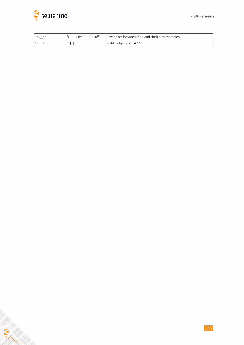
4 SBF Reference
Cov_zb f4 1 m2 −2 · 1010 Covariance between the z and clock bias estimates
Padding u1[..] Padding bytes, see 4.1.5
265

4 SBF Reference
PosCovGeodetic Number: 5906
"OnChange" interval: default PVT output rate (see 4.1.8)
This block contains the elements of the symmetric variance-covariance matrix of the
position expressed in the geodetic coordinates in the datum requested by the user:σ2ϕ σϕλ σϕh σϕbσλϕ σ2λ σλh σλbσhϕ σhλ σ2h σhbσbϕ σbλ σbh σ2b
Please refer to the PosCovCartesian block description for a general explanation of thecontents.
Note that the units of measure for all the variances and covariances, for height as
well as for latitude and longitude, are m2for ease of interpretation.
If the ellipsoidal height is not estimated (2D-mode), all height related components of
the variance-covariance matrix are undefined and set to their Do-Not-Use value.
266
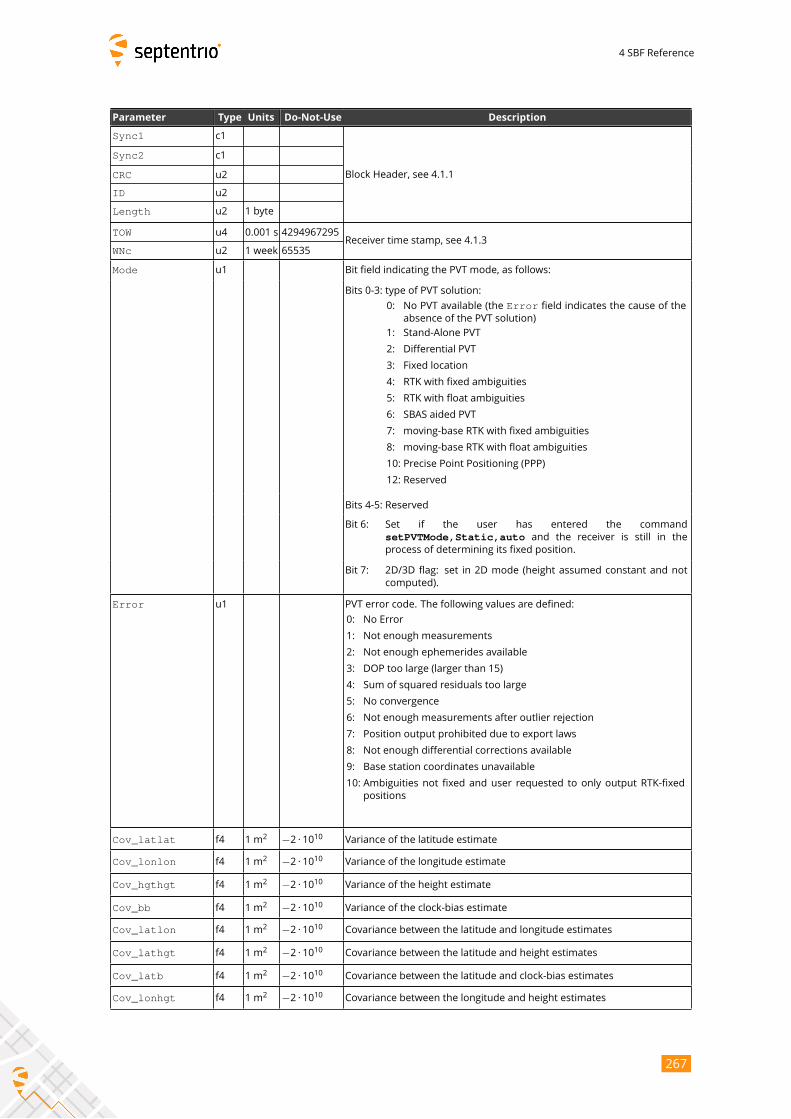
4 SBF Reference
Parameter Type Units Do-Not-Use Description
Sync1 c1
Block Header, see 4.1.1
Sync2 c1
CRC u2
ID u2
Length u2 1 byte
TOW u4 0.001 s 4294967295Receiver time stamp, see 4.1.3
WNc u2 1 week 65535
Mode u1 Bit field indicating the PVT mode, as follows:
Bits 0-3: type of PVT solution:
0: No PVT available (the Error field indicates the cause of the
absence of the PVT solution)
1: Stand-Alone PVT
2: Differential PVT
3: Fixed location
4: RTK with fixed ambiguities
5: RTK with float ambiguities
6: SBAS aided PVT
7: moving-base RTK with fixed ambiguities
8: moving-base RTK with float ambiguities
10: Precise Point Positioning (PPP)
12: Reserved
Bits 4-5: Reserved
Bit 6: Set if the user has entered the command
setPVTMode,Static,auto and the receiver is still in theprocess of determining its fixed position.
Bit 7: 2D/3D flag: set in 2D mode (height assumed constant and not
computed).
Error u1 PVT error code. The following values are defined:
0: No Error
1: Not enough measurements
2: Not enough ephemerides available
3: DOP too large (larger than 15)
4: Sum of squared residuals too large
5: No convergence
6: Not enough measurements after outlier rejection
7: Position output prohibited due to export laws
8: Not enough differential corrections available
9: Base station coordinates unavailable
10: Ambiguities not fixed and user requested to only output RTK-fixed
positions
Cov_latlat f4 1 m2 −2 · 1010 Variance of the latitude estimate
Cov_lonlon f4 1 m2 −2 · 1010 Variance of the longitude estimate
Cov_hgthgt f4 1 m2 −2 · 1010 Variance of the height estimate
Cov_bb f4 1 m2 −2 · 1010 Variance of the clock-bias estimate
Cov_latlon f4 1 m2 −2 · 1010 Covariance between the latitude and longitude estimates
Cov_lathgt f4 1 m2 −2 · 1010 Covariance between the latitude and height estimates
Cov_latb f4 1 m2 −2 · 1010 Covariance between the latitude and clock-bias estimates
Cov_lonhgt f4 1 m2 −2 · 1010 Covariance between the longitude and height estimates
267
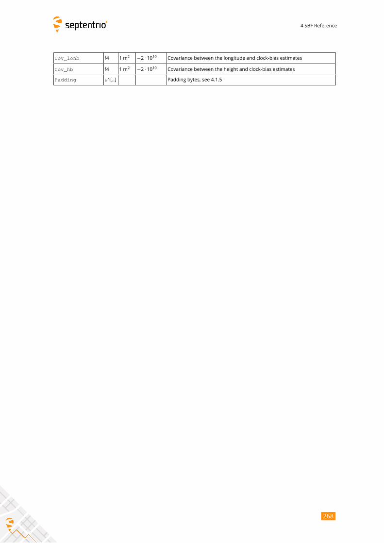
4 SBF Reference
Cov_lonb f4 1 m2 −2 · 1010 Covariance between the longitude and clock-bias estimates
Cov_hb f4 1 m2 −2 · 1010 Covariance between the height and clock-bias estimates
Padding u1[..] Padding bytes, see 4.1.5
268
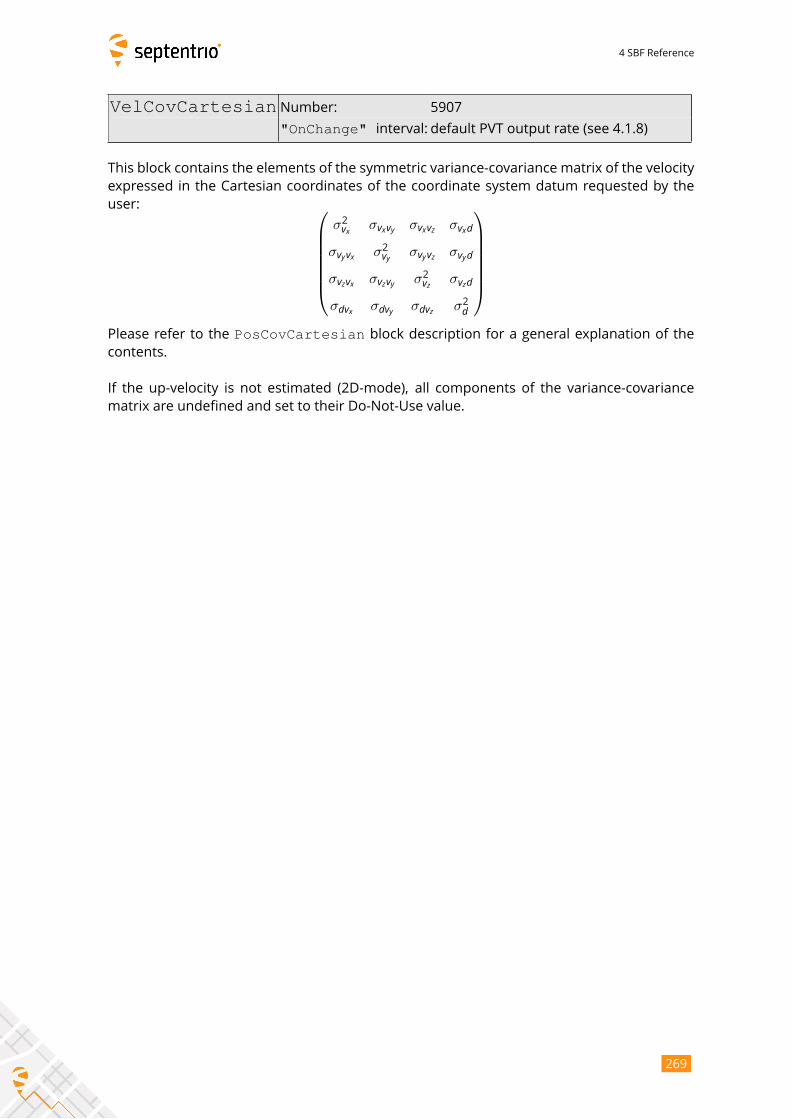
4 SBF Reference
VelCovCartesian Number: 5907
"OnChange" interval: default PVT output rate (see 4.1.8)
This block contains the elements of the symmetric variance-covariance matrix of the velocity
expressed in the Cartesian coordinates of the coordinate system datum requested by the
user: σ2vx σvxvy σvxvz σvxdσvyvx σ2vy σvyvz σvydσvzvx σvzvy σ2vz σvzdσdvx σdvy σdvz σ2d
Please refer to the PosCovCartesian block description for a general explanation of thecontents.
If the up-velocity is not estimated (2D-mode), all components of the variance-covariance
matrix are undefined and set to their Do-Not-Use value.
269

4 SBF Reference
Parameter Type Units Do-Not-Use Description
Sync1 c1
Block Header, see 4.1.1
Sync2 c1
CRC u2
ID u2
Length u2 1 byte
TOW u4 0.001 s 4294967295Receiver time stamp, see 4.1.3
WNc u2 1 week 65535
Mode u1 Bit field indicating the PVT mode, as follows:
Bits 0-3: type of PVT solution:
0: No PVT available (the Error field indicates the cause of theabsence of the PVT solution)
1: Stand-Alone PVT
2: Differential PVT
3: Fixed location
4: RTK with fixed ambiguities
5: RTK with float ambiguities
6: SBAS aided PVT
7: moving-base RTK with fixed ambiguities
8: moving-base RTK with float ambiguities
10: Precise Point Positioning (PPP)
12: Reserved
Bits 4-5: Reserved
Bit 6: Set if the user has entered the command
setPVTMode,Static,auto and the receiver is still in
the process of determining its fixed position.
Bit 7: 2D/3D flag: set in 2D mode (height assumed constant and not
computed).
Error u1 PVT error code. The following values are defined:
0: No Error
1: Not enough measurements
2: Not enough ephemerides available
3: DOP too large (larger than 15)
4: Sum of squared residuals too large
5: No convergence
6: Not enough measurements after outlier rejection
7: Position output prohibited due to export laws
8: Not enough differential corrections available
9: Base station coordinates unavailable
10: Ambiguities not fixed and user requested to only output RTK-fixed
positions
Cov_VxVx f4 1 m2/ s2 −2 · 1010 Variance of the x-velocity estimate
Cov_VyVy f4 1 m2/ s2 −2 · 1010 Variance of the y-velocity estimate
Cov_VzVz f4 1 m2/ s2 −2 · 1010 Variance of the z-velocity estimate
Cov_DtDt f4 1 m2/ s2 −2 · 1010 Variance of the clock drift estimate
Cov_VxVy f4 1 m2/ s2 −2 · 1010 Covariance between the x- and y-velocity estimates
Cov_VxVz f4 1 m2/ s2 −2 · 1010 Covariance between the x- and z-velocity estimates
Cov_VxDt f4 1 m2/ s2 −2 · 1010 Covariance between the x-velocity and the clock drift estimates
Cov_VyVz f4 1 m2/ s2 −2 · 1010 Covariance between the y- and z-velocity estimates
270
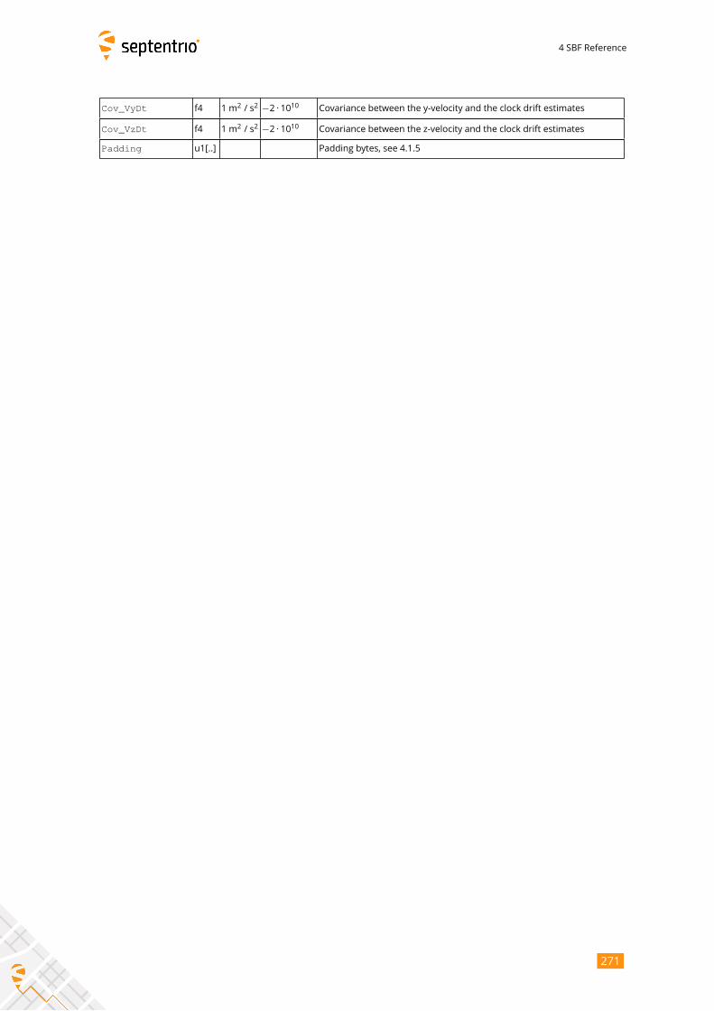
4 SBF Reference
Cov_VyDt f4 1 m2/ s2 −2 · 1010 Covariance between the y-velocity and the clock drift estimates
Cov_VzDt f4 1 m2/ s2 −2 · 1010 Covariance between the z-velocity and the clock drift estimates
Padding u1[..] Padding bytes, see 4.1.5
271
4 SBF Reference
VelCovGeodetic Number: 5908
"OnChange" interval: default PVT output rate (see 4.1.8)
This block contains the elements of the symmetric variance-covariance matrix of the velocity
expressed in the geodetic coordinates in the datum requested by the user:σ2vN σvNvE σvNvU σvNdσvEvN σ2vE σvEvU σvEdσvUvN σvUvE σ2vU σvUdσdvN σdvE σdvU σ2d
Please refer to the PosCovCartesian block description for a general explanation of thecontents.
If the up-velocity is not estimated (2D-mode), all up-velocity related components of
the variance-covariance matrix are undefined and set to their Do-Not-Use value.
272
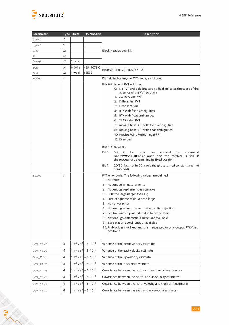
4 SBF Reference
Parameter Type Units Do-Not-Use Description
Sync1 c1
Block Header, see 4.1.1
Sync2 c1
CRC u2
ID u2
Length u2 1 byte
TOW u4 0.001 s 4294967295Receiver time stamp, see 4.1.3
WNc u2 1 week 65535
Mode u1 Bit field indicating the PVT mode, as follows:
Bits 0-3: type of PVT solution:
0: No PVT available (the Error field indicates the cause of theabsence of the PVT solution)
1: Stand-Alone PVT
2: Differential PVT
3: Fixed location
4: RTK with fixed ambiguities
5: RTK with float ambiguities
6: SBAS aided PVT
7: moving-base RTK with fixed ambiguities
8: moving-base RTK with float ambiguities
10: Precise Point Positioning (PPP)
12: Reserved
Bits 4-5: Reserved
Bit 6: Set if the user has entered the command
setPVTMode,Static,auto and the receiver is still in
the process of determining its fixed position.
Bit 7: 2D/3D flag: set in 2D mode (height assumed constant and not
computed).
Error u1 PVT error code. The following values are defined:
0: No Error
1: Not enough measurements
2: Not enough ephemerides available
3: DOP too large (larger than 15)
4: Sum of squared residuals too large
5: No convergence
6: Not enough measurements after outlier rejection
7: Position output prohibited due to export laws
8: Not enough differential corrections available
9: Base station coordinates unavailable
10: Ambiguities not fixed and user requested to only output RTK-fixed
positions
Cov_VnVn f4 1 m2/ s2 −2 · 1010 Variance of the north-velocity estimate
Cov_VeVe f4 1 m2/ s2 −2 · 1010 Variance of the east-velocity estimate
Cov_VuVu f4 1 m2/ s2 −2 · 1010 Variance of the up-velocity estimate
Cov_DtDt f4 1 m2/ s2 −2 · 1010 Variance of the clock drift estimate
Cov_VnVe f4 1 m2/ s2 −2 · 1010 Covariance between the north- and east-velocity estimates
Cov_VnVu f4 1 m2/ s2 −2 · 1010 Covariance between the north- and up-velocity estimates
Cov_VnDt f4 1 m2/ s2 −2 · 1010 Covariance between the north-velocity and clock drift estimates
Cov_VeVu f4 1 m2/ s2 −2 · 1010 Covariance between the east- and up-velocity estimates
273

4 SBF Reference
Cov_VeDt f4 1 m2/ s2 −2 · 1010 Covariance between the east-velocity and clock drift estimates
Cov_VuDt f4 1 m2/ s2 −2 · 1010 Covariance between the up-velocity and clock drift estimates
Padding u1[..] Padding bytes, see 4.1.5
274
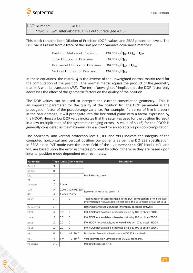
4 SBF Reference
DOP Number: 4001
"OnChange" interval: default PVT output rate (see 4.1.8)
This block contains both Dilution of Precision (DOP) values and SBAS protection levels. The
DOP values result from a trace of the unit position variance-covariance matrices:
Position Dilution of Precision: PDOP =√Qxx +Qyy +QzzTime Dilution of Precision: TDOP =√QbbHorizontal Dilution of Precision: HDOP =√Qλλ +Qϕϕ
Vertical Dilution of Precision: VDOP =√QhhIn these equations, the matrix Q is the inverse of the unweighted normal matrix used for
the computation of the position. The normal matrix equals the product of the geometry
matrix A with its transpose (AtA). The term "unweighted" implies that the DOP factor onlyaddresses the effect of the geometric factors on the quality of the position.
The DOP values can be used to interpret the current constellation geometry. This is
an important parameter for the quality of the position fix: the DOP parameter is the
propagation factor of the pseudorange variance. For example, if an error of 5 m is present
in the pseudorange, it will propagate into the horizontal plane with a factor expressed by
the HDOP. Hence a low DOP value indicates that the satellites used for the position fix result
in a low multiplication of the systematic ranging errors. A value of six (6) for the PDOP is
generally considered as themaximum value allowed for an acceptable position computation.
The horizontal and vertical protection levels (HPL and VPL) indicate the integrity of the
computed horizontal and vertical position components as per the DO 229 specification.
In SBAS-aided PVT mode (see the Mode field of the PVTCartesian SBF block), HPL andVPL are based upon the error estimates provided by SBAS. Otherwise they are based upon
internal position-mode dependent error estimates.
Parameter Type Units Do-Not-Use Description
Sync1 c1
Block Header, see 4.1.1
Sync2 c1
CRC u2
ID u2
Length u2 1 byte
TOW u4 0.001 s 4294967295Receiver time stamp, see 4.1.3
WNc u2 1 week 65535
NrSV u1 0 Total number of satellites used in the DOP computation, or 0 if the DOP
information is not available (in that case, the xDOP fields are all set to 0)
Reserved u1 Reserved for future use, to be ignored by decoding software
PDOP u2 0.01 0 If 0, PDOP not available, otherwise divide by 100 to obtain PDOP.
TDOP u2 0.01 0 If 0, TDOP not available, otherwise divide by 100 to obtain TDOP.
HDOP u2 0.01 0 If 0, HDOP not available, otherwise divide by 100 to obtain HDOP.
VDOP u2 0.01 0 If 0, VDOP not available, otherwise divide by 100 to obtain VDOP.
HPL f4 1 m −2 · 1010 Horizontal Protection Level (see the DO 229 standard).
VPL f4 1 m −2 · 1010 Vertical Protection Level (see the DO 229 standard).
Padding u1[..] Padding bytes, see 4.1.5
275
4 SBF Reference
PosCart Number: 4044
"OnChange" interval: default PVT output rate (see 4.1.8)
This block contains the absolute and relative (relative to the nearest base station) position
at the time specified in the TOW and WNc fields. The time of applicability is specified in the
receiver time frame.
The absolute position (X, Y, Z) is reported in a Cartesian coordinate system using the
datum indicated in the Datum field. The position is that of the marker. The ARP-to-marker
offset is set through the command setAntennaOffset.
For highest accuracy, the receiver tries to compute the baseline (Base2RoverX,Base2RoverY, Base2RoverZ) from rover ARP to base ARP. See the description of
the BaseVectorCart block for details.
Accurate ARP-to-ARP baseline is guaranteed only if both bits 0 and 1 of the Misc field
are set. Otherwise, centimeter-level offsets may arise because the receiver cannot make the
distinction between phase center and ARP positions. See section 2.5 for a discussion on the
phase center and ARP positions.
This block also contains the variance-covariance information and DOP factors associ-
ated with the position.
276
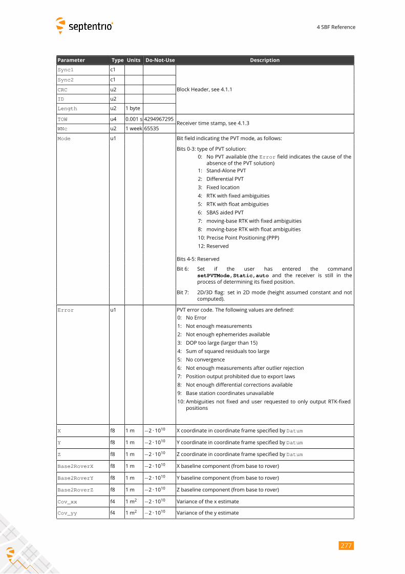
4 SBF Reference
Parameter Type Units Do-Not-Use Description
Sync1 c1
Block Header, see 4.1.1
Sync2 c1
CRC u2
ID u2
Length u2 1 byte
TOW u4 0.001 s 4294967295Receiver time stamp, see 4.1.3
WNc u2 1 week 65535
Mode u1 Bit field indicating the PVT mode, as follows:
Bits 0-3: type of PVT solution:
0: No PVT available (the Error field indicates the cause of the
absence of the PVT solution)
1: Stand-Alone PVT
2: Differential PVT
3: Fixed location
4: RTK with fixed ambiguities
5: RTK with float ambiguities
6: SBAS aided PVT
7: moving-base RTK with fixed ambiguities
8: moving-base RTK with float ambiguities
10: Precise Point Positioning (PPP)
12: Reserved
Bits 4-5: Reserved
Bit 6: Set if the user has entered the command
setPVTMode,Static,auto and the receiver is still in theprocess of determining its fixed position.
Bit 7: 2D/3D flag: set in 2D mode (height assumed constant and not
computed).
Error u1 PVT error code. The following values are defined:
0: No Error
1: Not enough measurements
2: Not enough ephemerides available
3: DOP too large (larger than 15)
4: Sum of squared residuals too large
5: No convergence
6: Not enough measurements after outlier rejection
7: Position output prohibited due to export laws
8: Not enough differential corrections available
9: Base station coordinates unavailable
10: Ambiguities not fixed and user requested to only output RTK-fixed
positions
X f8 1 m −2 · 1010 X coordinate in coordinate frame specified by Datum
Y f8 1 m −2 · 1010 Y coordinate in coordinate frame specified by Datum
Z f8 1 m −2 · 1010 Z coordinate in coordinate frame specified by Datum
Base2RoverX f8 1 m −2 · 1010 X baseline component (from base to rover)
Base2RoverY f8 1 m −2 · 1010 Y baseline component (from base to rover)
Base2RoverZ f8 1 m −2 · 1010 Z baseline component (from base to rover)
Cov_xx f4 1 m2 −2 · 1010 Variance of the x estimate
Cov_yy f4 1 m2 −2 · 1010 Variance of the y estimate
277
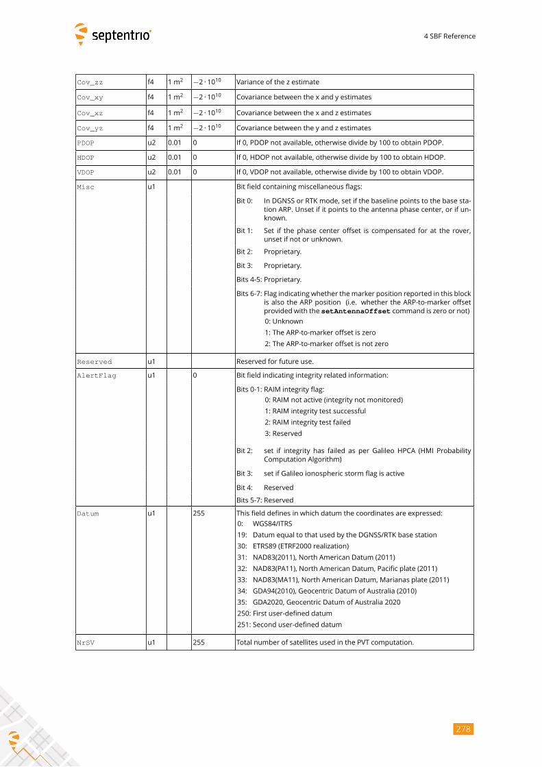
4 SBF Reference
Cov_zz f4 1 m2 −2 · 1010 Variance of the z estimate
Cov_xy f4 1 m2 −2 · 1010 Covariance between the x and y estimates
Cov_xz f4 1 m2 −2 · 1010 Covariance between the x and z estimates
Cov_yz f4 1 m2 −2 · 1010 Covariance between the y and z estimates
PDOP u2 0.01 0 If 0, PDOP not available, otherwise divide by 100 to obtain PDOP.
HDOP u2 0.01 0 If 0, HDOP not available, otherwise divide by 100 to obtain HDOP.
VDOP u2 0.01 0 If 0, VDOP not available, otherwise divide by 100 to obtain VDOP.
Misc u1 Bit field containing miscellaneous flags:
Bit 0: In DGNSS or RTK mode, set if the baseline points to the base sta-
tion ARP. Unset if it points to the antenna phase center, or if un-
known.
Bit 1: Set if the phase center offset is compensated for at the rover,
unset if not or unknown.
Bit 2: Proprietary.
Bit 3: Proprietary.
Bits 4-5: Proprietary.
Bits 6-7: Flag indicating whether themarker position reported in this block
is also the ARP position (i.e. whether the ARP-to-marker offset
provided with the setAntennaOffset command is zero or not)
0: Unknown
1: The ARP-to-marker offset is zero
2: The ARP-to-marker offset is not zero
Reserved u1 Reserved for future use.
AlertFlag u1 0 Bit field indicating integrity related information:
Bits 0-1: RAIM integrity flag:
0: RAIM not active (integrity not monitored)
1: RAIM integrity test successful
2: RAIM integrity test failed
3: Reserved
Bit 2: set if integrity has failed as per Galileo HPCA (HMI Probability
Computation Algorithm)
Bit 3: set if Galileo ionospheric storm flag is active
Bit 4: Reserved
Bits 5-7: Reserved
Datum u1 255 This field defines in which datum the coordinates are expressed:
0: WGS84/ITRS
19: Datum equal to that used by the DGNSS/RTK base station
30: ETRS89 (ETRF2000 realization)
31: NAD83(2011), North American Datum (2011)
32: NAD83(PA11), North American Datum, Pacific plate (2011)
33: NAD83(MA11), North American Datum, Marianas plate (2011)
34: GDA94(2010), Geocentric Datum of Australia (2010)
35: GDA2020, Geocentric Datum of Australia 2020
250: First user-defined datum
251: Second user-defined datum
NrSV u1 255 Total number of satellites used in the PVT computation.
278
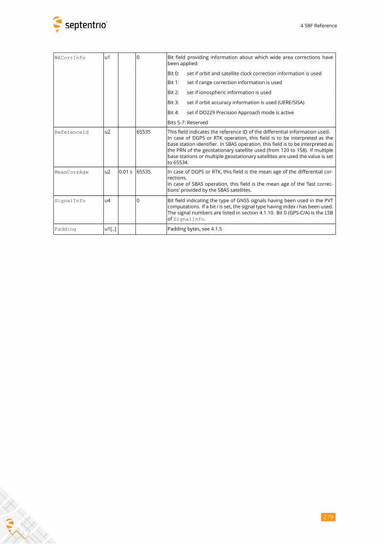
4 SBF Reference
WACorrInfo u1 0 Bit field providing information about which wide area corrections have
been applied:
Bit 0: set if orbit and satellite clock correction information is used
Bit 1: set if range correction information is used
Bit 2: set if ionospheric information is used
Bit 3: set if orbit accuracy information is used (UERE/SISA)
Bit 4: set if DO229 Precision Approach mode is active
Bits 5-7: Reserved
ReferenceId u2 65535 This field indicates the reference ID of the differential information used.
In case of DGPS or RTK operation, this field is to be interpreted as the
base station identifier. In SBAS operation, this field is to be interpreted as
the PRN of the geostationary satellite used (from 120 to 158). If multiple
base stations or multiple geostationary satellites are used the value is set
to 65534.
MeanCorrAge u2 0.01 s 65535 In case of DGPS or RTK, this field is the mean age of the differential cor-
rections.
In case of SBAS operation, this field is the mean age of the ’fast correc-
tions’ provided by the SBAS satellites.
SignalInfo u4 0 Bit field indicating the type of GNSS signals having been used in the PVT
computations. If a bit i is set, the signal type having index i has been used.The signal numbers are listed in section 4.1.10. Bit 0 (GPS-C/A) is the LSB
of SignalInfo.
Padding u1[..] Padding bytes, see 4.1.5
279
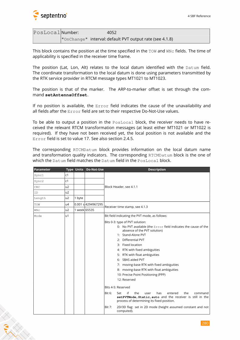
4 SBF Reference
PosLocal Number: 4052
"OnChange" interval: default PVT output rate (see 4.1.8)
This block contains the position at the time specified in the TOW and WNc fields. The time ofapplicability is specified in the receiver time frame.
The position (Lat, Lon, Alt) relates to the local datum identified with the Datum field.
The coordinate transformation to the local datum is done using parameters transmitted by
the RTK service provider in RTCM message types MT1021 to MT1023.
The position is that of the marker. The ARP-to-marker offset is set through the com-
mand setAntennaOffset.
If no position is available, the Error field indicates the cause of the unavailability and
all fields after the Error field are set to their respective Do-Not-Use values.
To be able to output a position in the PosLocal block, the receiver needs to have re-ceived the relevant RTCM transformation messages (at least either MT1021 or MT1022 is
required). If they have not been received yet, the local position is not available and the
Error field is set to value 17. See also section 2.4.5.
The corresponding RTCMDatum block provides information on the local datum name
and transformation quality indicators. The corresponding RTCMDatum block is the one ofwhich the Datum field matches the Datum field in the PosLocal block.
Parameter Type Units Do-Not-Use Description
Sync1 c1
Block Header, see 4.1.1
Sync2 c1
CRC u2
ID u2
Length u2 1 byte
TOW u4 0.001 s 4294967295Receiver time stamp, see 4.1.3
WNc u2 1 week 65535
Mode u1 Bit field indicating the PVT mode, as follows:
Bits 0-3: type of PVT solution:
0: No PVT available (the Error field indicates the cause of the
absence of the PVT solution)
1: Stand-Alone PVT
2: Differential PVT
3: Fixed location
4: RTK with fixed ambiguities
5: RTK with float ambiguities
6: SBAS aided PVT
7: moving-base RTK with fixed ambiguities
8: moving-base RTK with float ambiguities
10: Precise Point Positioning (PPP)
12: Reserved
Bits 4-5: Reserved
Bit 6: Set if the user has entered the command
setPVTMode,Static,auto and the receiver is still in theprocess of determining its fixed position.
Bit 7: 2D/3D flag: set in 2D mode (height assumed constant and not
computed).
280
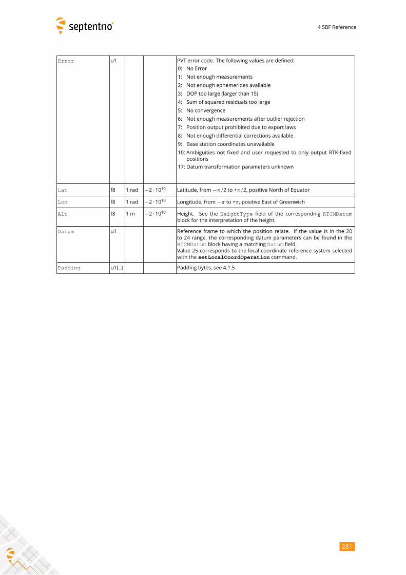
4 SBF Reference
Error u1 PVT error code. The following values are defined:
0: No Error
1: Not enough measurements
2: Not enough ephemerides available
3: DOP too large (larger than 15)
4: Sum of squared residuals too large
5: No convergence
6: Not enough measurements after outlier rejection
7: Position output prohibited due to export laws
8: Not enough differential corrections available
9: Base station coordinates unavailable
10: Ambiguities not fixed and user requested to only output RTK-fixed
positions
17: Datum transformation parameters unknown
Lat f8 1 rad −2 · 1010 Latitude, from−π/2 to +π/2, positive North of Equator
Lon f8 1 rad −2 · 1010 Longitude, from−π to +π, positive East of Greenwich
Alt f8 1 m −2 · 1010 Height. See the HeightType field of the corresponding RTCMDatumblock for the interpretation of the height.
Datum u1 Reference frame to which the position relate. If the value is in the 20
to 24 range, the corresponding datum parameters can be found in the
RTCMDatum block having a matching Datum field.Value 25 corresponds to the local coordinate reference system selected
with the setLocalCoordOperation command.
Padding u1[..] Padding bytes, see 4.1.5
281
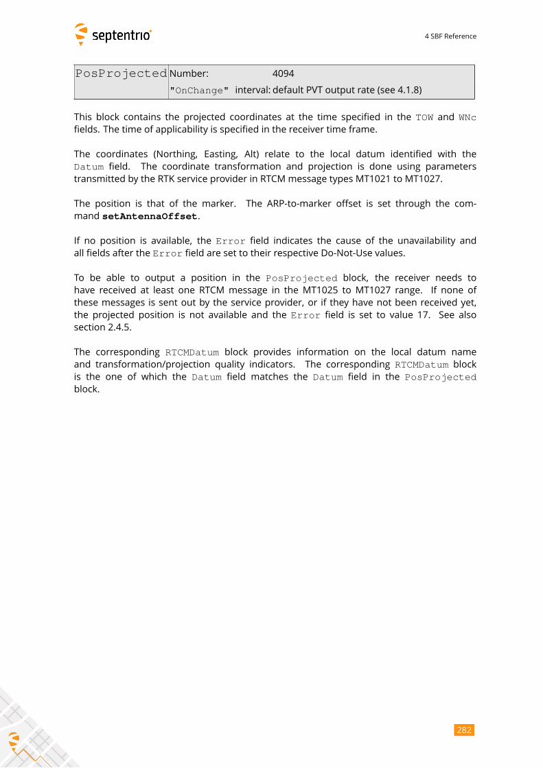
4 SBF Reference
PosProjected Number: 4094
"OnChange" interval: default PVT output rate (see 4.1.8)
This block contains the projected coordinates at the time specified in the TOW and WNcfields. The time of applicability is specified in the receiver time frame.
The coordinates (Northing, Easting, Alt) relate to the local datum identified with the
Datum field. The coordinate transformation and projection is done using parameters
transmitted by the RTK service provider in RTCM message types MT1021 to MT1027.
The position is that of the marker. The ARP-to-marker offset is set through the com-
mand setAntennaOffset.
If no position is available, the Error field indicates the cause of the unavailability and
all fields after the Error field are set to their respective Do-Not-Use values.
To be able to output a position in the PosProjected block, the receiver needs tohave received at least one RTCM message in the MT1025 to MT1027 range. If none of
these messages is sent out by the service provider, or if they have not been received yet,
the projected position is not available and the Error field is set to value 17. See also
section 2.4.5.
The corresponding RTCMDatum block provides information on the local datum name
and transformation/projection quality indicators. The corresponding RTCMDatum blockis the one of which the Datum field matches the Datum field in the PosProjectedblock.
282
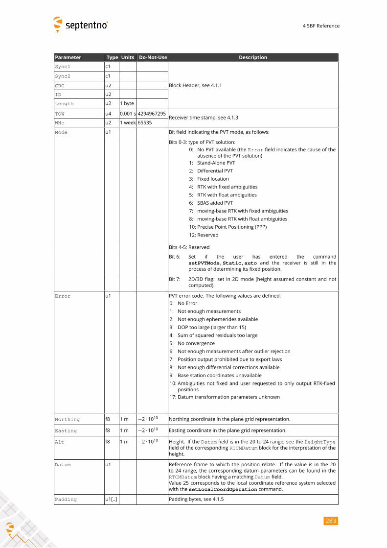
4 SBF Reference
Parameter Type Units Do-Not-Use Description
Sync1 c1
Block Header, see 4.1.1
Sync2 c1
CRC u2
ID u2
Length u2 1 byte
TOW u4 0.001 s 4294967295Receiver time stamp, see 4.1.3
WNc u2 1 week 65535
Mode u1 Bit field indicating the PVT mode, as follows:
Bits 0-3: type of PVT solution:
0: No PVT available (the Error field indicates the cause of the
absence of the PVT solution)
1: Stand-Alone PVT
2: Differential PVT
3: Fixed location
4: RTK with fixed ambiguities
5: RTK with float ambiguities
6: SBAS aided PVT
7: moving-base RTK with fixed ambiguities
8: moving-base RTK with float ambiguities
10: Precise Point Positioning (PPP)
12: Reserved
Bits 4-5: Reserved
Bit 6: Set if the user has entered the command
setPVTMode,Static,auto and the receiver is still in theprocess of determining its fixed position.
Bit 7: 2D/3D flag: set in 2D mode (height assumed constant and not
computed).
Error u1 PVT error code. The following values are defined:
0: No Error
1: Not enough measurements
2: Not enough ephemerides available
3: DOP too large (larger than 15)
4: Sum of squared residuals too large
5: No convergence
6: Not enough measurements after outlier rejection
7: Position output prohibited due to export laws
8: Not enough differential corrections available
9: Base station coordinates unavailable
10: Ambiguities not fixed and user requested to only output RTK-fixed
positions
17: Datum transformation parameters unknown
Northing f8 1 m −2 · 1010 Northing coordinate in the plane grid representation.
Easting f8 1 m −2 · 1010 Easting coordinate in the plane grid representation.
Alt f8 1 m −2 · 1010 Height. If the Datum field is in the 20 to 24 range, see the HeightTypefield of the corresponding RTCMDatum block for the interpretation of theheight.
Datum u1 Reference frame to which the position relate. If the value is in the 20
to 24 range, the corresponding datum parameters can be found in the
RTCMDatum block having a matching Datum field.Value 25 corresponds to the local coordinate reference system selected
with the setLocalCoordOperation command.
Padding u1[..] Padding bytes, see 4.1.5
283
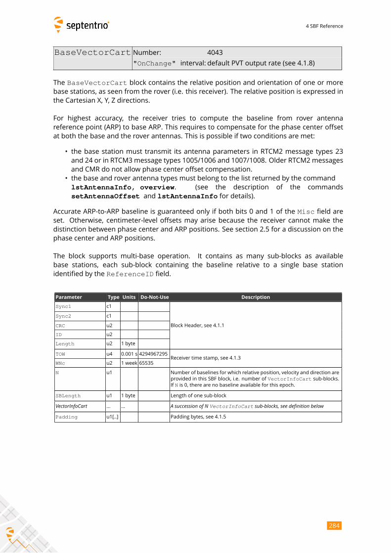
4 SBF Reference
BaseVectorCart Number: 4043
"OnChange" interval: default PVT output rate (see 4.1.8)
The BaseVectorCart block contains the relative position and orientation of one or morebase stations, as seen from the rover (i.e. this receiver). The relative position is expressed in
the Cartesian X, Y, Z directions.
For highest accuracy, the receiver tries to compute the baseline from rover antenna
reference point (ARP) to base ARP. This requires to compensate for the phase center offset
at both the base and the rover antennas. This is possible if two conditions are met:
• the base station must transmit its antenna parameters in RTCM2 message types 23
and 24 or in RTCM3message types 1005/1006 and 1007/1008. Older RTCM2messages
and CMR do not allow phase center offset compensation.
• the base and rover antenna types must belong to the list returned by the command
lstAntennaInfo, overview. (see the description of the commands
setAntennaOffset and lstAntennaInfo for details).
Accurate ARP-to-ARP baseline is guaranteed only if both bits 0 and 1 of the Misc field are
set. Otherwise, centimeter-level offsets may arise because the receiver cannot make the
distinction between phase center and ARP positions. See section 2.5 for a discussion on the
phase center and ARP positions.
The block supports multi-base operation. It contains as many sub-blocks as available
base stations, each sub-block containing the baseline relative to a single base station
identified by the ReferenceID field.
Parameter Type Units Do-Not-Use Description
Sync1 c1
Block Header, see 4.1.1
Sync2 c1
CRC u2
ID u2
Length u2 1 byte
TOW u4 0.001 s 4294967295Receiver time stamp, see 4.1.3
WNc u2 1 week 65535
N u1 Number of baselines for which relative position, velocity and direction are
provided in this SBF block, i.e. number of VectorInfoCart sub-blocks.If N is 0, there are no baseline available for this epoch.
SBLength u1 1 byte Length of one sub-block
VectorInfoCart ... ... A succession of N VectorInfoCart sub-blocks, see definition belowPadding u1[..] Padding bytes, see 4.1.5
284
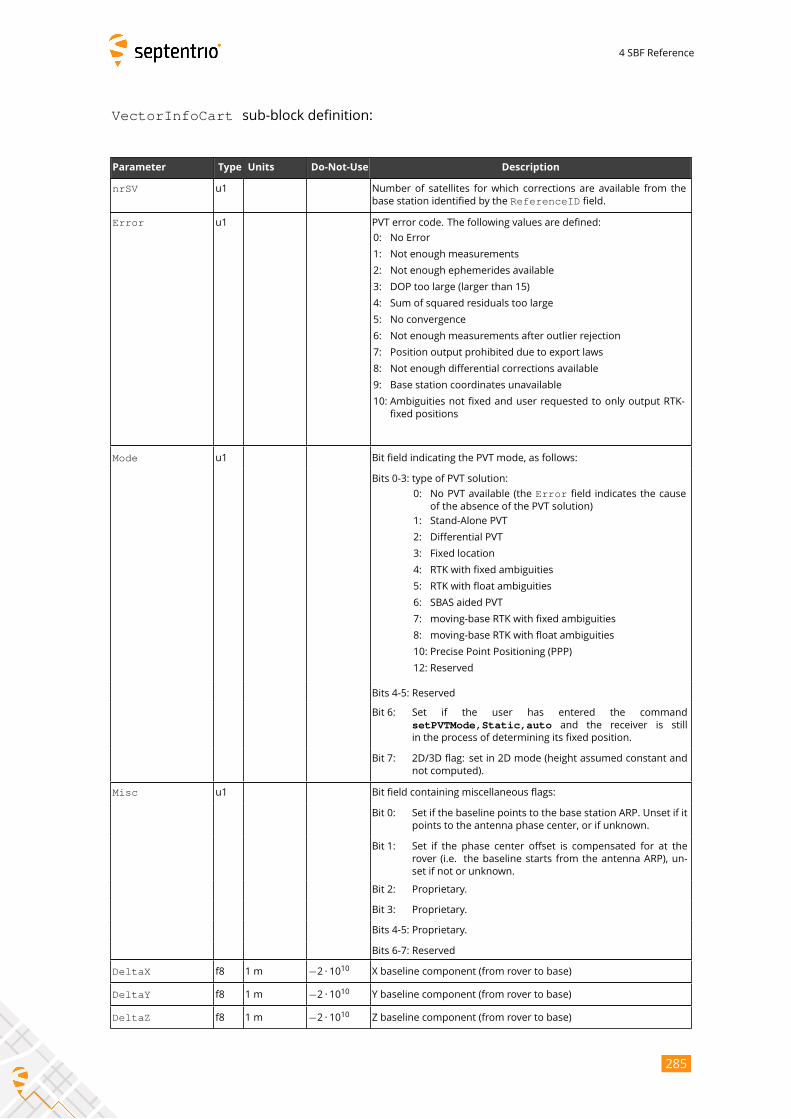
4 SBF Reference
VectorInfoCart sub-block definition:
Parameter Type Units Do-Not-Use Description
nrSV u1 Number of satellites for which corrections are available from the
base station identified by the ReferenceID field.
Error u1 PVT error code. The following values are defined:
0: No Error
1: Not enough measurements
2: Not enough ephemerides available
3: DOP too large (larger than 15)
4: Sum of squared residuals too large
5: No convergence
6: Not enough measurements after outlier rejection
7: Position output prohibited due to export laws
8: Not enough differential corrections available
9: Base station coordinates unavailable
10: Ambiguities not fixed and user requested to only output RTK-
fixed positions
Mode u1 Bit field indicating the PVT mode, as follows:
Bits 0-3: type of PVT solution:
0: No PVT available (the Error field indicates the cause
of the absence of the PVT solution)
1: Stand-Alone PVT
2: Differential PVT
3: Fixed location
4: RTK with fixed ambiguities
5: RTK with float ambiguities
6: SBAS aided PVT
7: moving-base RTK with fixed ambiguities
8: moving-base RTK with float ambiguities
10: Precise Point Positioning (PPP)
12: Reserved
Bits 4-5: Reserved
Bit 6: Set if the user has entered the command
setPVTMode,Static,auto and the receiver is still
in the process of determining its fixed position.
Bit 7: 2D/3D flag: set in 2D mode (height assumed constant and
not computed).
Misc u1 Bit field containing miscellaneous flags:
Bit 0: Set if the baseline points to the base station ARP. Unset if it
points to the antenna phase center, or if unknown.
Bit 1: Set if the phase center offset is compensated for at the
rover (i.e. the baseline starts from the antenna ARP), un-
set if not or unknown.
Bit 2: Proprietary.
Bit 3: Proprietary.
Bits 4-5: Proprietary.
Bits 6-7: Reserved
DeltaX f8 1 m −2 · 1010 X baseline component (from rover to base)
DeltaY f8 1 m −2 · 1010 Y baseline component (from rover to base)
DeltaZ f8 1 m −2 · 1010 Z baseline component (from rover to base)
285

4 SBF Reference
DeltaVx f4 1 m / s −2 · 1010 X velocity of base with respect to rover
DeltaVy f4 1 m / s −2 · 1010 Y velocity of base with respect to rover
DeltaVz f4 1 m / s −2 · 1010 Z velocity of base with respect to rover
Azimuth u2 0.01 degrees 65535 Azimuth of the base station (from 0 to 360◦, increasing towards
east)
Elevation i2 0.01 degrees −32768 Elevation of the base station (from -90◦to 90
◦)
ReferenceID u2 Base station ID
CorrAge u2 0.01 s 65535 Age of the oldest differential correction used for this baseline com-
putation.
SignalInfo u4 0 Bit field indicating the GNSS signals for which differential
corrections are available from the base station identified by
ReferenceID. If bit i is set, corrections for the signal type havingindex i are available. The signal numbers are listed in section 4.1.10.Bit 0 (GPS-C/A) is the LSB of SignalInfo.
Padding u1[..] Padding bytes, see 4.1.5
286
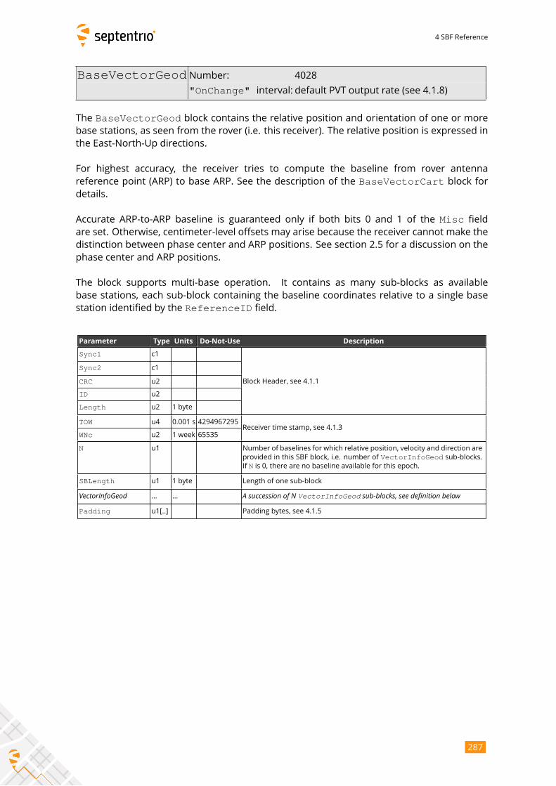
4 SBF Reference
BaseVectorGeod Number: 4028
"OnChange" interval: default PVT output rate (see 4.1.8)
The BaseVectorGeod block contains the relative position and orientation of one or morebase stations, as seen from the rover (i.e. this receiver). The relative position is expressed in
the East-North-Up directions.
For highest accuracy, the receiver tries to compute the baseline from rover antenna
reference point (ARP) to base ARP. See the description of the BaseVectorCart block fordetails.
Accurate ARP-to-ARP baseline is guaranteed only if both bits 0 and 1 of the Misc field
are set. Otherwise, centimeter-level offsets may arise because the receiver cannot make the
distinction between phase center and ARP positions. See section 2.5 for a discussion on the
phase center and ARP positions.
The block supports multi-base operation. It contains as many sub-blocks as available
base stations, each sub-block containing the baseline coordinates relative to a single base
station identified by the ReferenceID field.
Parameter Type Units Do-Not-Use Description
Sync1 c1
Block Header, see 4.1.1
Sync2 c1
CRC u2
ID u2
Length u2 1 byte
TOW u4 0.001 s 4294967295Receiver time stamp, see 4.1.3
WNc u2 1 week 65535
N u1 Number of baselines for which relative position, velocity and direction are
provided in this SBF block, i.e. number of VectorInfoGeod sub-blocks.If N is 0, there are no baseline available for this epoch.
SBLength u1 1 byte Length of one sub-block
VectorInfoGeod ... ... A succession of N VectorInfoGeod sub-blocks, see definition belowPadding u1[..] Padding bytes, see 4.1.5
287

4 SBF Reference
VectorInfoGeod sub-block definition:
Parameter Type Units Do-Not-Use Description
NrSV u1 Number of satellites for which corrections are available from the
base station identified by the ReferenceID field.
Error u1 PVT error code. The following values are defined:
0: No Error
1: Not enough measurements
2: Not enough ephemerides available
3: DOP too large (larger than 15)
4: Sum of squared residuals too large
5: No convergence
6: Not enough measurements after outlier rejection
7: Position output prohibited due to export laws
8: Not enough differential corrections available
9: Base station coordinates unavailable
10: Ambiguities not fixed and user requested to only output RTK-
fixed positions
Mode u1 Bit field indicating the PVT mode, as follows:
Bits 0-3: type of PVT solution:
0: No PVT available (the Error field indicates the cause
of the absence of the PVT solution)
1: Stand-Alone PVT
2: Differential PVT
3: Fixed location
4: RTK with fixed ambiguities
5: RTK with float ambiguities
6: SBAS aided PVT
7: moving-base RTK with fixed ambiguities
8: moving-base RTK with float ambiguities
10: Precise Point Positioning (PPP)
12: Reserved
Bits 4-5: Reserved
Bit 6: Set if the user has entered the command
setPVTMode,Static,auto and the receiver is still
in the process of determining its fixed position.
Bit 7: 2D/3D flag: set in 2D mode (height assumed constant and
not computed).
Misc u1 Bit field containing miscellaneous flags:
Bit 0: Set if the baseline points to the base station ARP. Unset if it
points to the antenna phase center, or if unknown.
Bit 1: Set if the phase center offset is compensated for at the
rover (i.e. the baseline starts from the antenna ARP), un-
set if not or unknown.
Bit 2: Proprietary.
Bit 3: Proprietary.
Bits 4-5: Proprietary.
Bits 6-7: Reserved
DeltaEast f8 1 m −2 · 1010 East baseline component (from rover to base)
DeltaNorth f8 1 m −2 · 1010 North baseline component (from rover to base)
DeltaUp f8 1 m −2 · 1010 Up baseline component (from rover to base)
288
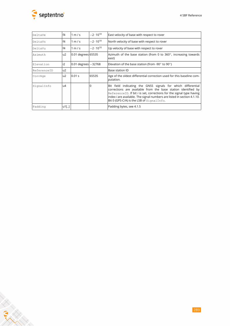
4 SBF Reference
DeltaVe f4 1 m / s −2 · 1010 East velocity of base with respect to rover
DeltaVn f4 1 m / s −2 · 1010 North velocity of base with respect to rover
DeltaVu f4 1 m / s −2 · 1010 Up velocity of base with respect to rover
Azimuth u2 0.01 degrees 65535 Azimuth of the base station (from 0 to 360◦, increasing towards
east)
Elevation i2 0.01 degrees −32768 Elevation of the base station (from -90◦to 90
◦)
ReferenceID u2 Base station ID
CorrAge u2 0.01 s 65535 Age of the oldest differential correction used for this baseline com-
putation.
SignalInfo u4 0 Bit field indicating the GNSS signals for which differential
corrections are available from the base station identified by
ReferenceID. If bit i is set, corrections for the signal type havingindex i are available. The signal numbers are listed in section 4.1.10.Bit 0 (GPS-C/A) is the LSB of SignalInfo.
Padding u1[..] Padding bytes, see 4.1.5
289

4 SBF Reference
PVTSupport Number: 4076
"OnChange" interval: default PVT output rate (see 4.1.8)
This block contains various internal parameters that can be used for maintenance and
support.
The detailed definition of this block is not available in this document.
290
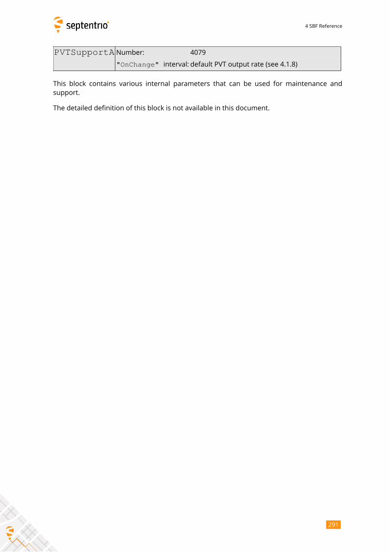
4 SBF Reference
PVTSupportA Number: 4079
"OnChange" interval: default PVT output rate (see 4.1.8)
This block contains various internal parameters that can be used for maintenance and
support.
The detailed definition of this block is not available in this document.
291

4 SBF Reference
EndOfPVT Number: 5921
"OnChange" interval: default PVT output rate (see 4.1.8)
This block marks the end of transmission of all PVT related blocks belonging to the same
epoch.
Parameter Type Units Do-Not-Use Description
Sync1 c1
Block Header, see 4.1.1
Sync2 c1
CRC u2
ID u2
Length u2 1 byte
TOW u4 0.001 s 4294967295Receiver time stamp, see 4.1.3
WNc u2 1 week 65535
Padding u1[..] Padding bytes, see 4.1.5
292
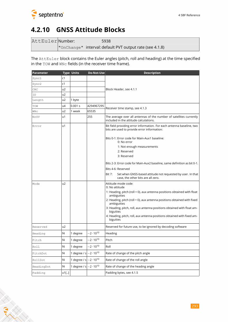
4 SBF Reference
4.2.10 GNSS Attitude Blocks
AttEuler Number: 5938
"OnChange" interval: default PVT output rate (see 4.1.8)
The AttEuler block contains the Euler angles (pitch, roll and heading) at the time specifiedin the TOW and WNc fields (in the receiver time frame).
Parameter Type Units Do-Not-Use Description
Sync1 c1
Block Header, see 4.1.1
Sync2 c1
CRC u2
ID u2
Length u2 1 byte
TOW u4 0.001 s 4294967295Receiver time stamp, see 4.1.3
WNc u2 1 week 65535
NrSV u1 255 The average over all antennas of the number of satellites currently
included in the attitude calculations.
Error u1 Bit field providing error information. For each antenna baseline, two
bits are used to provide error information:
Bits 0-1: Error code for Main-Aux1 baseline:
0: No error
1: Not enough measurements
2: Reserved
3: Reserved
Bits 2-3: Error code forMain-Aux2 baseline, same definition as bit 0-1.
Bits 4-6: Reserved
Bit 7: Set when GNSS-based attitude not requested by user. In that
case, the other bits are all zero.
Mode u2 Attitude mode code:
0: No attitude
1: Heading, pitch (roll = 0), aux antenna positions obtained with float
ambiguities
2: Heading, pitch (roll = 0), aux antenna positions obtained with fixed
ambiguities
3: Heading, pitch, roll, aux antenna positions obtained with float am-
biguities
4: Heading, pitch, roll, aux antenna positions obtained with fixed am-
biguities
Reserved u2 Reserved for future use, to be ignored by decoding software
Heading f4 1 degree −2 · 1010 Heading
Pitch f4 1 degree −2 · 1010 Pitch
Roll f4 1 degree −2 · 1010 Roll
PitchDot f4 1 degree / s −2 · 1010 Rate of change of the pitch angle
RollDot f4 1 degree / s −2 · 1010 Rate of change of the roll angle
HeadingDot f4 1 degree / s −2 · 1010 Rate of change of the heading angle
Padding u1[..] Padding bytes, see 4.1.5
293
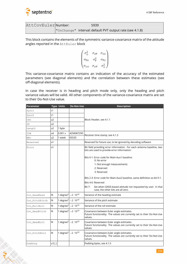
4 SBF Reference
AttCovEuler Number: 5939
"OnChange" interval: default PVT output rate (see 4.1.8)
This block contains the elements of the symmetric variance-covariance matrix of the attitude
angles reported in the AttEuler blockσ2ϕ σϕθ σϕψ
σθϕ σ2θ σθψ
σψϕ σψθ σ2ψ
This variance-covariance matrix contains an indication of the accuracy of the estimated
parameters (see diagonal elements) and the correlation between these estimates (see
off-diagonal elements).
In case the receiver is in heading and pitch mode only, only the heading and pitch
variance values will be valid. All other components of the variance-covariance matrix are set
to their Do-Not-Use value.
Parameter Type Units Do-Not-Use Description
Sync1 c1
Block Header, see 4.1.1
Sync2 c1
CRC u2
ID u2
Length u2 1 byte
TOW u4 0.001 s 4294967295Receiver time stamp, see 4.1.3
WNc u2 1 week 65535
Reserved u1 Reserved for future use, to be ignored by decoding software
Error u1 Bit field providing error information. For each antenna baseline, two
bits are used to provide error information:
Bits 0-1: Error code for Main-Aux1 baseline:
0: No error
1: Not enough measurements
2: Reserved
3: Reserved
Bits 2-3: Error code for Main-Aux2 baseline, same definition as bit 0-1.
Bits 4-6: Reserved
Bit 7: Set when GNSS-based attitude not requested by user. In that
case, the other bits are all zero.
Cov_HeadHead f4 1 degree2 −2 · 1010 Variance of the heading estimate
Cov_PitchPitch f4 1 degree2 −2 · 1010 Variance of the pitch estimate
Cov_RollRoll f4 1 degree2 −2 · 1010 Variance of the roll estimate
Cov_HeadPitch f4 1 degree2 −2 · 1010 Covariance between Euler angle estimates.
Future functionality. The values are currently set to their Do-Not-Use
values.
Cov_HeadRoll f4 1 degree2 −2 · 1010 Covariance between Euler angle estimates.
Future functionality. The values are currently set to their Do-Not-Use
values.
Cov_PitchRoll f4 1 degree2 −2 · 1010 Covariance between Euler angle estimates.
Future functionality. The values are currently set to their Do-Not-Use
values.
Padding u1[..] Padding bytes, see 4.1.5
294
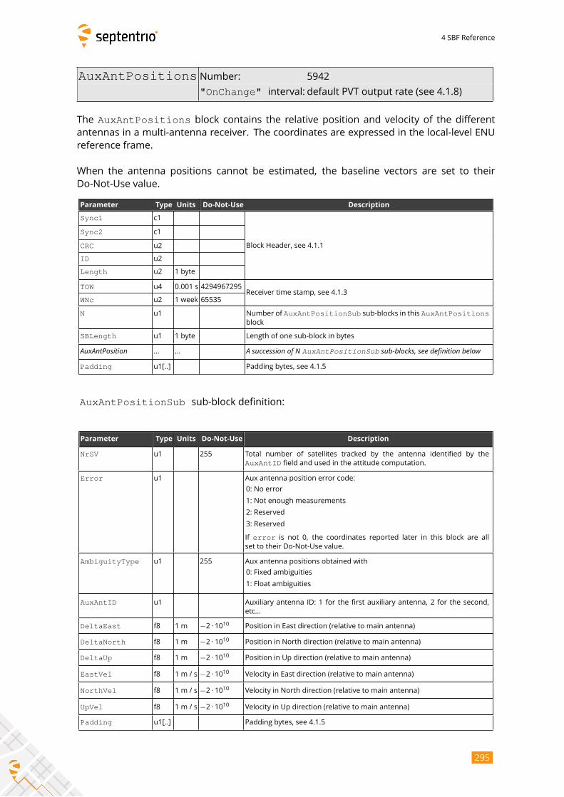
4 SBF Reference
AuxAntPositions Number: 5942
"OnChange" interval: default PVT output rate (see 4.1.8)
The AuxAntPositions block contains the relative position and velocity of the differentantennas in a multi-antenna receiver. The coordinates are expressed in the local-level ENU
reference frame.
When the antenna positions cannot be estimated, the baseline vectors are set to their
Do-Not-Use value.
Parameter Type Units Do-Not-Use Description
Sync1 c1
Block Header, see 4.1.1
Sync2 c1
CRC u2
ID u2
Length u2 1 byte
TOW u4 0.001 s 4294967295Receiver time stamp, see 4.1.3
WNc u2 1 week 65535
N u1 Number of AuxAntPositionSub sub-blocks in this AuxAntPositionsblock
SBLength u1 1 byte Length of one sub-block in bytes
AuxAntPosition ... ... A succession of N AuxAntPositionSub sub-blocks, see definition belowPadding u1[..] Padding bytes, see 4.1.5
AuxAntPositionSub sub-block definition:
Parameter Type Units Do-Not-Use Description
NrSV u1 255 Total number of satellites tracked by the antenna identified by the
AuxAntID field and used in the attitude computation.
Error u1 Aux antenna position error code:
0: No error
1: Not enough measurements
2: Reserved
3: Reserved
If error is not 0, the coordinates reported later in this block are allset to their Do-Not-Use value.
AmbiguityType u1 255 Aux antenna positions obtained with
0: Fixed ambiguities
1: Float ambiguities
AuxAntID u1 Auxiliary antenna ID: 1 for the first auxiliary antenna, 2 for the second,
etc...
DeltaEast f8 1 m −2 · 1010 Position in East direction (relative to main antenna)
DeltaNorth f8 1 m −2 · 1010 Position in North direction (relative to main antenna)
DeltaUp f8 1 m −2 · 1010 Position in Up direction (relative to main antenna)
EastVel f8 1 m / s −2 · 1010 Velocity in East direction (relative to main antenna)
NorthVel f8 1 m / s −2 · 1010 Velocity in North direction (relative to main antenna)
UpVel f8 1 m / s −2 · 1010 Velocity in Up direction (relative to main antenna)
Padding u1[..] Padding bytes, see 4.1.5
295
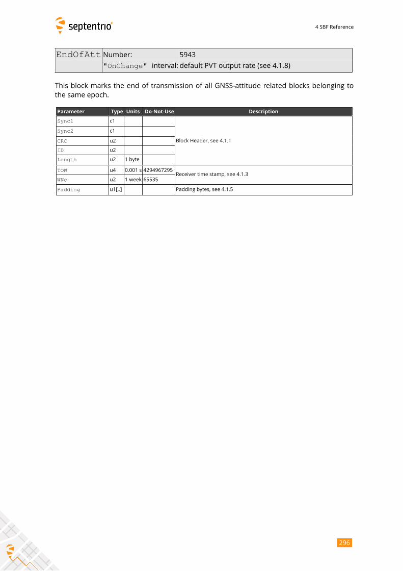
4 SBF Reference
EndOfAtt Number: 5943
"OnChange" interval: default PVT output rate (see 4.1.8)
This block marks the end of transmission of all GNSS-attitude related blocks belonging to
the same epoch.
Parameter Type Units Do-Not-Use Description
Sync1 c1
Block Header, see 4.1.1
Sync2 c1
CRC u2
ID u2
Length u2 1 byte
TOW u4 0.001 s 4294967295Receiver time stamp, see 4.1.3
WNc u2 1 week 65535
Padding u1[..] Padding bytes, see 4.1.5
296
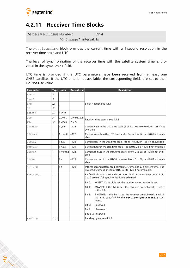
4 SBF Reference
4.2.11 Receiver Time Blocks
ReceiverTime Number: 5914
"OnChange" interval: 1s
The ReceiverTime block provides the current time with a 1-second resolution in thereceiver time scale and UTC.
The level of synchronization of the receiver time with the satellite system time is pro-
vided in the SyncLevel field.
UTC time is provided if the UTC parameters have been received from at least one
GNSS satellite. If the UTC time is not available, the corresponding fields are set to their
Do-Not-Use value.
Parameter Type Units Do-Not-Use Description
Sync1 c1
Block Header, see 4.1.1
Sync2 c1
CRC u2
ID u2
Length u2 1 byte
TOW u4 0.001 s 4294967295Receiver time stamp, see 4.1.3
WNc u2 1 week 65535
UTCYear i1 1 year −128 Current year in the UTC time scale (2 digits). From 0 to 99, or -128 if not
available
UTCMonth i1 1 month −128 Current month in the UTC time scale. From 1 to 12, or -128 if not avail-
able
UTCDay i1 1 day −128 Current day in the UTC time scale. From 1 to 31, or -128 if not available
UTCHour i1 1 hour −128 Current hour in the UTC time scale. From 0 to 23, or -128 if not available
UTCMin i1 1 minute −128 Current minute in the UTC time scale. From 0 to 59, or -128 if not avail-
able
UTCSec i1 1 s −128 Current second in the UTC time scale. From 0 to 59, or -128 if not avail-
able
DeltaLS i1 1 s −128 Integer second difference between UTC time and GPS system time. Pos-
itive if GPS time is ahead of UTC. Set to -128 if not available.
SyncLevel u1 Bit field indicating the synchronization level of the receiver time. If bits
0 to 2 are set, full synchronization is achieved:
Bit 0: WNSET: if this bit is set, the receiver week number is set.
Bit 1: TOWSET: if this bit is set, the receiver time-of-week is set to
within 20ms.
Bit 2: FINETIME: if this bit is set, the receiver time-of-week is within
the limit specified by the setClockSyncThreshold com-mand.
Bit 3: Reserved
Bit 4: i Reserved
Bits 5-7: Reserved
Padding u1[..] Padding bytes, see 4.1.5
297
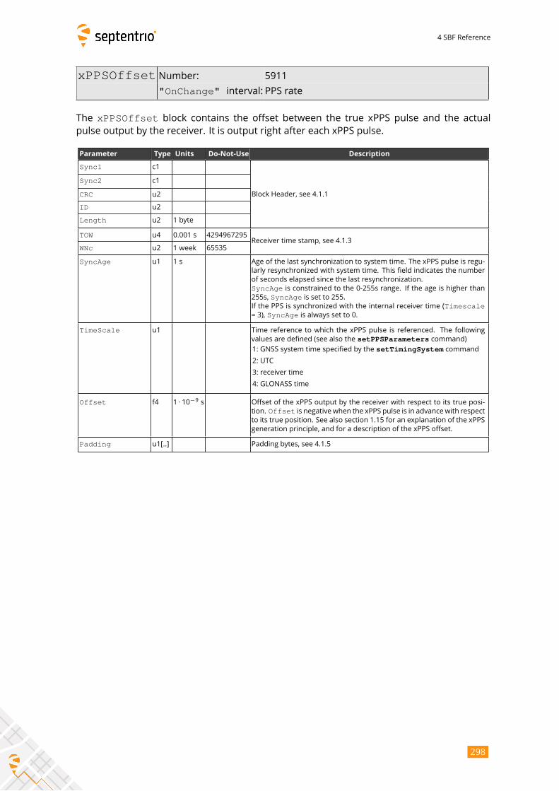
4 SBF Reference
xPPSOffset Number: 5911
"OnChange" interval: PPS rate
The xPPSOffset block contains the offset between the true xPPS pulse and the actualpulse output by the receiver. It is output right after each xPPS pulse.
Parameter Type Units Do-Not-Use Description
Sync1 c1
Block Header, see 4.1.1
Sync2 c1
CRC u2
ID u2
Length u2 1 byte
TOW u4 0.001 s 4294967295Receiver time stamp, see 4.1.3
WNc u2 1 week 65535
SyncAge u1 1 s Age of the last synchronization to system time. The xPPS pulse is regu-
larly resynchronized with system time. This field indicates the number
of seconds elapsed since the last resynchronization.
SyncAge is constrained to the 0-255s range. If the age is higher than255s, SyncAge is set to 255.If the PPS is synchronized with the internal receiver time (Timescale= 3), SyncAge is always set to 0.
TimeScale u1 Time reference to which the xPPS pulse is referenced. The following
values are defined (see also the setPPSParameters command)1: GNSS system time specified by the setTimingSystem command
2: UTC
3: receiver time
4: GLONASS time
Offset f4 1 · 10−9s Offset of the xPPS output by the receiver with respect to its true posi-
tion. Offset is negative when the xPPS pulse is in advance with respectto its true position. See also section 1.15 for an explanation of the xPPS
generation principle, and for a description of the xPPS offset.
Padding u1[..] Padding bytes, see 4.1.5
298
4 SBF Reference
4.2.12 External Event Blocks
These blocks report the state of the receiver applicable at the instant of a level tran-
sition on one of its “Event” pins. The receiver time is reported in the ExtEvent SBFblock, and the receiver position is reported in the ExtEventPVTCartesian and theExtEventPVTGeodetic blocks.
If enabled, upon detection of an event, these three blocks are output in the following order,
with no other SBF blocks in between them:
1. ExtEvent;2. ExtEventPVTCartesian;3. ExtEventPVTGeodetic.
All blocks referring to the same event contain the same time stamp in the TOW and WNc fields.
299
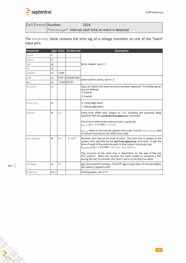
4 SBF Reference
ExtEvent Number: 5924
"OnChange" interval: each time an event is detected
The ExtEvent block contains the time tag of a voltage transition on one of the "Event"input pins.
Parameter Type Units Do-Not-Use Description
Sync1 c1
Block Header, see 4.1.1
Sync2 c1
CRC u2
ID u2
Length u2 1 byte
TOW u4 0.001 s 4294967295External time stamp, see 4.1.3
WNc u2 1 week 65535
Source u1 Input pin where this external event has been detected. The following val-
ues are defined:
1: EventA
2: EventB
Polarity u1 0: rising edge event
1: falling edge event
Offset f4 1 s Event time offset with respect to TOW, including the potential delayspecified with the setEventParameters command.
The time of week of the external event is given by:
text,rx [s] = TOW/1000 + Offset
text,rx refers to the receiver system time scale. Use the RxClkBias fieldto convert this time to the GNSS time scale.
RxClkBias f8 1 s −2 · 1010 Receiver clock bias at the time of event. The clock bias is relative to the
system time specified by the setTimingSystem command. To get thetime of week of the external event in that system time scale, use:
text,GNSS [s] = TOW/1000 + Offset - RxClkBias.
The accuracy of the clock bias is dependent on the age of the last
PVT solution. When the receiver has been unable to compute a PVT
during the last 10 minutes, this field is set to its Do-Not-Use value.
PVTAge u2 1 s Age of the last PVT solution. If the PVT age is larger than 10minutes (600s),
this value is clipped to 600.Rev 1
Padding u1[..] Padding bytes, see 4.1.5
300
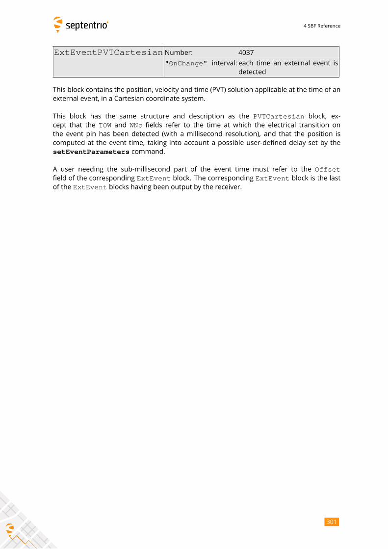
4 SBF Reference
ExtEventPVTCartesian Number: 4037
"OnChange" interval: each time an external event isdetected
This block contains the position, velocity and time (PVT) solution applicable at the time of an
external event, in a Cartesian coordinate system.
This block has the same structure and description as the PVTCartesian block, ex-cept that the TOW and WNc fields refer to the time at which the electrical transition on
the event pin has been detected (with a millisecond resolution), and that the position is
computed at the event time, taking into account a possible user-defined delay set by the
setEventParameters command.
A user needing the sub-millisecond part of the event time must refer to the Offsetfield of the corresponding ExtEvent block. The corresponding ExtEvent block is the lastof the ExtEvent blocks having been output by the receiver.
301

4 SBF Reference
Parameter Type Units Do-Not-Use Description
Sync1 c1
Block Header, see 4.1.1
Sync2 c1
CRC u2
ID u2
Length u2 1 byte
TOW u4 0.001 s 4294967295External time stamp, see 4.1.3
WNc u2 1 week 65535
Mode u1 Bit field indicating the PVT mode, as follows:
Bits 0-3: type of PVT solution:
0: No PVT available (the Error field indicates the cause of
the absence of the PVT solution)
1: Stand-Alone PVT
2: Differential PVT
3: Fixed location
4: RTK with fixed ambiguities
5: RTK with float ambiguities
6: SBAS aided PVT
7: moving-base RTK with fixed ambiguities
8: moving-base RTK with float ambiguities
10: Precise Point Positioning (PPP)
12: Reserved
Bits 4-5: Reserved
Bit 6: Set if the user has entered the command
setPVTMode,Static,auto and the receiver is still in
the process of determining its fixed position.
Bit 7: 2D/3D flag: set in 2D mode (height assumed constant and
not computed).
Error u1 PVT error code. The following values are defined:
0: No Error
1: Not enough measurements
2: Not enough ephemerides available
3: DOP too large (larger than 15)
4: Sum of squared residuals too large
5: No convergence
6: Not enough measurements after outlier rejection
7: Position output prohibited due to export laws
8: Not enough differential corrections available
9: Base station coordinates unavailable
10: Ambiguities not fixed and user requested to only output RTK-fixed
positions
X f8 1 m −2 · 1010 X coordinate in coordinate frame specified by Datum
Y f8 1 m −2 · 1010 Y coordinate in coordinate frame specified by Datum
Z f8 1 m −2 · 1010 Z coordinate in coordinate frame specified by Datum
Undulation f4 1 m −2 · 1010 Geoid undulation. See the setGeoidUndulation command.
Vx f4 1 m / s −2 · 1010 Not applicable
Vy f4 1 m / s −2 · 1010 Not applicable
Vz f4 1 m / s −2 · 1010 Not applicable
302

4 SBF Reference
COG f4 1 degree −2 · 1010 Course over ground: this is defined as the angle of the vehicle with re-
spect to the local level North, ranging from 0 to 360, and increasing to-
wards east. Set to the Do-Not-Use value when the speed is lower than
0.1m/s.
RxClkBias f8 1 ms −2 · 1010 Receiver clock bias relative to the GNSS system time reported in the
TimeSystem field. Positive when the receiver time is ahead of the sys-tem time. To transfer the receiver time to the system time, use:tGPS/GST = trx - RxClkBias
RxClkDrift f4 1 ppm −2 · 1010 Receiver clock drift relative to the GNSS system time (relative frequency
error). Positive when the receiver clock runs faster than the system time.
TimeSystem u1 255 Time system of which the offset is provided in this sub-block:
0: GPS time
1: Galileo time
3: GLONASS time
4: BeiDou time
5: QZSS time
Datum u1 255 This field defines in which datum the coordinates are expressed:
0: WGS84/ITRS
19: Datum equal to that used by the DGNSS/RTK base station
30: ETRS89 (ETRF2000 realization)
31: NAD83(2011), North American Datum (2011)
32: NAD83(PA11), North American Datum, Pacific plate (2011)
33: NAD83(MA11), North American Datum, Marianas plate (2011)
34: GDA94(2010), Geocentric Datum of Australia (2010)
35: GDA2020, Geocentric Datum of Australia 2020
250: First user-defined datum
251: Second user-defined datum
NrSV u1 255 Total number of satellites used in the PVT computation.
WACorrInfo u1 0 Bit field providing information about which wide area corrections have
been applied:
Bit 0: set if orbit and satellite clock correction information is used
Bit 1: set if range correction information is used
Bit 2: set if ionospheric information is used
Bit 3: set if orbit accuracy information is used (UERE/SISA)
Bit 4: set if DO229 Precision Approach mode is active
Bits 5-7: Reserved
ReferenceID u2 65535 This field indicates the reference ID of the differential information used.
In case of DGPS or RTK operation, this field is to be interpreted as the
base station identifier. In SBAS operation, this field is to be interpreted
as the PRN of the geostationary satellite used (from 120 to 158). If multi-
ple base stations or multiple geostationary satellites are used the value
is set to 65534.
MeanCorrAge u2 0.01 s 65535 In case of DGPS or RTK, this field is the mean age of the differential cor-
rections.
In case of SBAS operation, this field is the mean age of the ’fast correc-
tions’ provided by the SBAS satellites.
SignalInfo u4 0 Bit field indicating the type of GNSS signals having been used in the PVT
computations. If a bit i is set, the signal type having index i has beenused. The signal numbers are listed in section 4.1.10. Bit 0 (GPS-C/A) is
the LSB of SignalInfo.
303

4 SBF Reference
AlertFlag u1 0 Bit field indicating integrity related information:
Bits 0-1: RAIM integrity flag:
0: RAIM not active (integrity not monitored)
1: RAIM integrity test successful
2: RAIM integrity test failed
3: Reserved
Bit 2: set if integrity has failed as per Galileo HPCA (HMI Probability
Computation Algorithm)
Bit 3: set if Galileo ionospheric storm flag is active
Bit 4: Reserved
Bits 5-7: Reserved
NrBases u1 0 Number of base stations used in the PVT computation.
PPPInfo u2 0 Bit field containing PPP-related information:
1 s Bits 0-11: Age of the last seed, in seconds. The age is clipped to 4091s.
This field must be ignored when the seed type is 0 (see bits
13-15 below).
Bit 12: Reserved
Bits 13-15: Type of last seed:
0: Not seeded or not in PPP positioning mode
1: Manual seed
2: Seeded from DGPS
3: Seeded from RTKFixed
Rev 1
Latency u2 0.0001 s 65535 Time elapsed between the time of applicability of the position fix and
the generation of this SBF block by the receiver. This time includes the
receiver processing time, but not the communication latency.
HAccuracy u2 0.01 m 65535 2DRMS horizontal accuracy: twice the root-mean-square of the horizon-
tal distance error. The horizontal distance between the true position
and the computed position is expected to be lower than HAccuracywith a probability of at least 95%. The value is clipped to 65534
=655.34m
VAccuracy u2 0.01 m 65535 2-sigma vertical accuracy. The vertical distance between the true
position and the computed position is expected to be lower than
VAccuracy with a probability of at least 95%. The value is clipped to65534 =655.34m.
Misc u1 Bit field containing miscellaneous flags:
Bit 0: In DGNSS or RTK mode, set if the baseline points to the base
station ARP. Unset if it points to the antenna phase center, or
if unknown.
Bit 1: Set if the phase center offset is compensated for at the rover,
unset if not or unknown.
Bit 2: Proprietary.
Bit 3: Proprietary.
Bits 4-5: Proprietary.
Bits 6-7: Flag indicating whether the marker position reported in this
block is also the ARP position (i.e. whether the ARP-to-
marker offset provided with the setAntennaOffset com-mand is zero or not)
0: Unknown
1: The ARP-to-marker offset is zero
2: The ARP-to-marker offset is not zero
Rev 2
Padding u1[..] Padding bytes, see 4.1.5
304
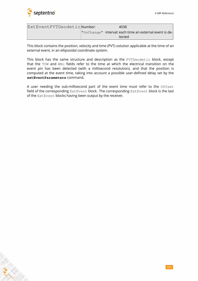
4 SBF Reference
ExtEventPVTGeodetic Number: 4038
"OnChange" interval: each time an external event is de-tected
This block contains the position, velocity and time (PVT) solution applicable at the time of an
external event, in an ellipsoidal coordinate system.
This block has the same structure and description as the PVTGeodetic block, exceptthat the TOW and WNc fields refer to the time at which the electrical transition on the
event pin has been detected (with a millisecond resolution), and that the position is
computed at the event time, taking into account a possible user-defined delay set by the
setEventParameters command.
A user needing the sub-millisecond part of the event time must refer to the Offsetfield of the corresponding ExtEvent block. The corresponding ExtEvent block is the lastof the ExtEvent blocks having been output by the receiver.
305
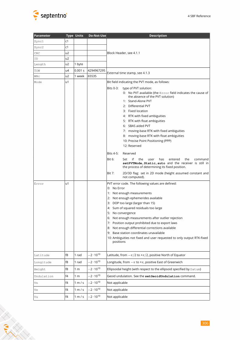
4 SBF Reference
Parameter Type Units Do-Not-Use Description
Sync1 c1
Block Header, see 4.1.1
Sync2 c1
CRC u2
ID u2
Length u2 1 byte
TOW u4 0.001 s 4294967295External time stamp, see 4.1.3
WNc u2 1 week 65535
Mode u1 Bit field indicating the PVT mode, as follows:
Bits 0-3: type of PVT solution:
0: No PVT available (the Error field indicates the cause of
the absence of the PVT solution)
1: Stand-Alone PVT
2: Differential PVT
3: Fixed location
4: RTK with fixed ambiguities
5: RTK with float ambiguities
6: SBAS aided PVT
7: moving-base RTK with fixed ambiguities
8: moving-base RTK with float ambiguities
10: Precise Point Positioning (PPP)
12: Reserved
Bits 4-5: Reserved
Bit 6: Set if the user has entered the command
setPVTMode,Static,auto and the receiver is still in
the process of determining its fixed position.
Bit 7: 2D/3D flag: set in 2D mode (height assumed constant and
not computed).
Error u1 PVT error code. The following values are defined:
0: No Error
1: Not enough measurements
2: Not enough ephemerides available
3: DOP too large (larger than 15)
4: Sum of squared residuals too large
5: No convergence
6: Not enough measurements after outlier rejection
7: Position output prohibited due to export laws
8: Not enough differential corrections available
9: Base station coordinates unavailable
10: Ambiguities not fixed and user requested to only output RTK-fixed
positions
Latitude f8 1 rad −2 · 1010 Latitude, from−π/2 to +π/2, positive North of Equator
Longitude f8 1 rad −2 · 1010 Longitude, from−π to +π, positive East of Greenwich
Height f8 1 m −2 · 1010 Ellipsoidal height (with respect to the ellipsoid specified by Datum)
Undulation f4 1 m −2 · 1010 Geoid undulation. See the setGeoidUndulation command.
Vn f4 1 m / s −2 · 1010 Not applicable
Ve f4 1 m / s −2 · 1010 Not applicable
Vu f4 1 m / s −2 · 1010 Not applicable
306

4 SBF Reference
COG f4 1 degree −2 · 1010 Course over ground: this is defined as the angle of the vehicle with re-
spect to the local level North, ranging from 0 to 360, and increasing to-
wards east. Set to the Do-Not-Use value when the speed is lower than
0.1m/s.
RxClkBias f8 1 ms −2 · 1010 Receiver clock bias relative to the GNSS system time reported in the
TimeSystem field. Positive when the receiver time is ahead of the sys-tem time. To transfer the receiver time to the system time, use:tGPS/GST = trx - RxClkBias
RxClkDrift f4 1 ppm −2 · 1010 Receiver clock drift relative to the GNSS system time (relative frequency
error). Positive when the receiver clock runs faster than the system time.
TimeSystem u1 255 Time system of which the offset is provided in this sub-block:
0: GPS time
1: Galileo time
3: GLONASS time
4: BeiDou time
5: QZSS time
Datum u1 255 This field defines in which datum the coordinates are expressed:
0: WGS84/ITRS
19: Datum equal to that used by the DGNSS/RTK base station
30: ETRS89 (ETRF2000 realization)
31: NAD83(2011), North American Datum (2011)
32: NAD83(PA11), North American Datum, Pacific plate (2011)
33: NAD83(MA11), North American Datum, Marianas plate (2011)
34: GDA94(2010), Geocentric Datum of Australia (2010)
35: GDA2020, Geocentric Datum of Australia 2020
250: First user-defined datum
251: Second user-defined datum
NrSV u1 255 Total number of satellites used in the PVT computation.
WACorrInfo u1 0 Bit field providing information about which wide area corrections have
been applied:
Bit 0: set if orbit and satellite clock correction information is used
Bit 1: set if range correction information is used
Bit 2: set if ionospheric information is used
Bit 3: set if orbit accuracy information is used (UERE/SISA)
Bit 4: set if DO229 Precision Approach mode is active
Bits 5-7: Reserved
ReferenceID u2 65535 This field indicates the reference ID of the differential information used.
In case of DGPS or RTK operation, this field is to be interpreted as the
base station identifier. In SBAS operation, this field is to be interpreted
as the PRN of the geostationary satellite used (from 120 to 158). If multi-
ple base stations or multiple geostationary satellites are used the value
is set to 65534.
MeanCorrAge u2 0.01 s 65535 In case of DGPS or RTK, this field is the mean age of the differential cor-
rections.
In case of SBAS operation, this field is the mean age of the ’fast correc-
tions’ provided by the SBAS satellites.
SignalInfo u4 0 Bit field indicating the type of GNSS signals having been used in the PVT
computations. If a bit i is set, the signal type having index i has beenused. The signal numbers are listed in section 4.1.10. Bit 0 (GPS-C/A) is
the LSB of SignalInfo.
307

4 SBF Reference
AlertFlag u1 0 Bit field indicating integrity related information:
Bits 0-1: RAIM integrity flag:
0: RAIM not active (integrity not monitored)
1: RAIM integrity test successful
2: RAIM integrity test failed
3: Reserved
Bit 2: set if integrity has failed as per Galileo HPCA (HMI Probability
Computation Algorithm)
Bit 3: set if Galileo ionospheric storm flag is active
Bit 4: Reserved
Bits 5-7: Reserved
NrBases u1 0 Number of base stations used in the PVT computation.
PPPInfo u2 0 Bit field containing PPP-related information:
1 s Bits 0-11: Age of the last seed, in seconds. The age is clipped to 4091s.
This field must be ignored when the seed type is 0 (see bits
13-15 below).
Bit 12: Reserved
Bits 13-15: Type of last seed:
0: Not seeded or not in PPP positioning mode
1: Manual seed
2: Seeded from DGPS
3: Seeded from RTKFixed
Rev 1
Latency u2 0.0001 s 65535 Time elapsed between the time of applicability of the position fix and
the generation of this SBF block by the receiver. This time includes the
receiver processing time, but not the communication latency.
HAccuracy u2 0.01 m 65535 2DRMS horizontal accuracy: twice the root-mean-square of the horizon-
tal distance error. The horizontal distance between the true position
and the computed position is expected to be lower than HAccuracywith a probability of at least 95%. The value is clipped to 65534
=655.34m
VAccuracy u2 0.01 m 65535 2-sigma vertical accuracy. The vertical distance between the true
position and the computed position is expected to be lower than
VAccuracy with a probability of at least 95%. The value is clipped to65534 =655.34m.
Misc u1 Bit field containing miscellaneous flags:
Bit 0: In DGNSS or RTK mode, set if the baseline points to the base
station ARP. Unset if it points to the antenna phase center, or
if unknown.
Bit 1: Set if the phase center offset is compensated for at the rover,
unset if not or unknown.
Bit 2: Proprietary.
Bit 3: Proprietary.
Bits 4-5: Proprietary.
Bits 6-7: Flag indicating whether the marker position reported in this
block is also the ARP position (i.e. whether the ARP-to-
marker offset provided with the setAntennaOffset com-mand is zero or not)
0: Unknown
1: The ARP-to-marker offset is zero
2: The ARP-to-marker offset is not zero
Rev 2
Padding u1[..] Padding bytes, see 4.1.5
308
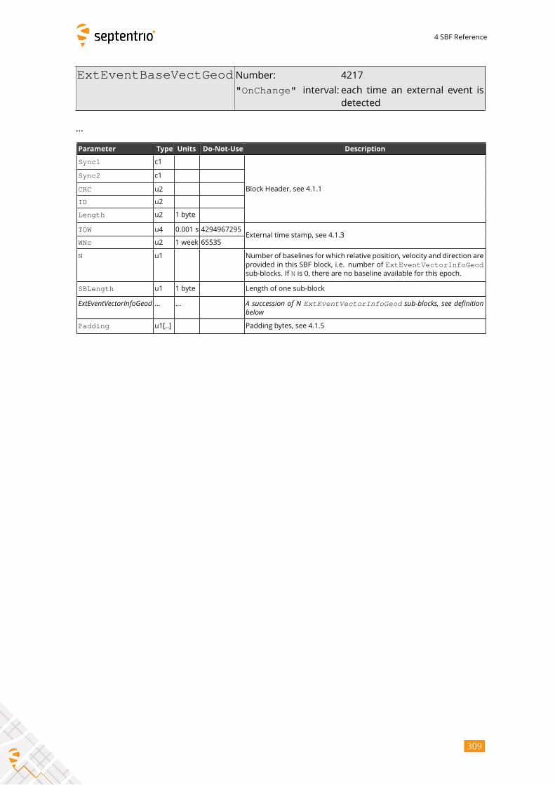
4 SBF Reference
ExtEventBaseVectGeod Number: 4217
"OnChange" interval: each time an external event isdetected
...
Parameter Type Units Do-Not-Use Description
Sync1 c1
Block Header, see 4.1.1
Sync2 c1
CRC u2
ID u2
Length u2 1 byte
TOW u4 0.001 s 4294967295External time stamp, see 4.1.3
WNc u2 1 week 65535
N u1 Number of baselines for which relative position, velocity and direction are
provided in this SBF block, i.e. number of ExtEventVectorInfoGeodsub-blocks. If N is 0, there are no baseline available for this epoch.
SBLength u1 1 byte Length of one sub-block
ExtEventVectorInfoGeod ... ... A succession of N ExtEventVectorInfoGeod sub-blocks, see definitionbelowPadding u1[..] Padding bytes, see 4.1.5
309

4 SBF Reference
ExtEventVectorInfoGeod sub-block definition:
Parameter Type Units Do-Not-Use Description
NrSV u1 Number of satellites for which corrections are available from the
base station identified by the ReferenceID field.
Error u1 PVT error code. The following values are defined:
0: No Error
1: Not enough measurements
2: Not enough ephemerides available
3: DOP too large (larger than 15)
4: Sum of squared residuals too large
5: No convergence
6: Not enough measurements after outlier rejection
7: Position output prohibited due to export laws
8: Not enough differential corrections available
9: Base station coordinates unavailable
10: Ambiguities not fixed and user requested to only output RTK-
fixed positions
Mode u1 Bit field indicating the PVT mode, as follows:
Bits 0-3: type of PVT solution:
0: No PVT available (the Error field indicates the cause
of the absence of the PVT solution)
1: Stand-Alone PVT
2: Differential PVT
3: Fixed location
4: RTK with fixed ambiguities
5: RTK with float ambiguities
6: SBAS aided PVT
7: moving-base RTK with fixed ambiguities
8: moving-base RTK with float ambiguities
10: Precise Point Positioning (PPP)
12: Reserved
Bits 4-5: Reserved
Bit 6: Set if the user has entered the command
setPVTMode,Static,auto and the receiver is still
in the process of determining its fixed position.
Bit 7: 2D/3D flag: set in 2D mode (height assumed constant and
not computed).
Misc u1 Bit field containing miscellaneous flags:
Bit 0: Set if the baseline points to the base station ARP. Unset if it
points to the antenna phase center, or if unknown.
Bit 1: Set if the phase center offset is compensated for at the
rover (i.e. the baseline starts from the antenna ARP), un-
set if not or unknown.
Bit 2: Proprietary.
Bit 3: Proprietary.
Bits 4-5: Proprietary.
Bits 6-7: Reserved
DeltaEast f8 1 m −2 · 1010 East baseline component (from rover to base)
DeltaNorth f8 1 m −2 · 1010 North baseline component (from rover to base)
DeltaUp f8 1 m −2 · 1010 Up baseline component (from rover to base)
310
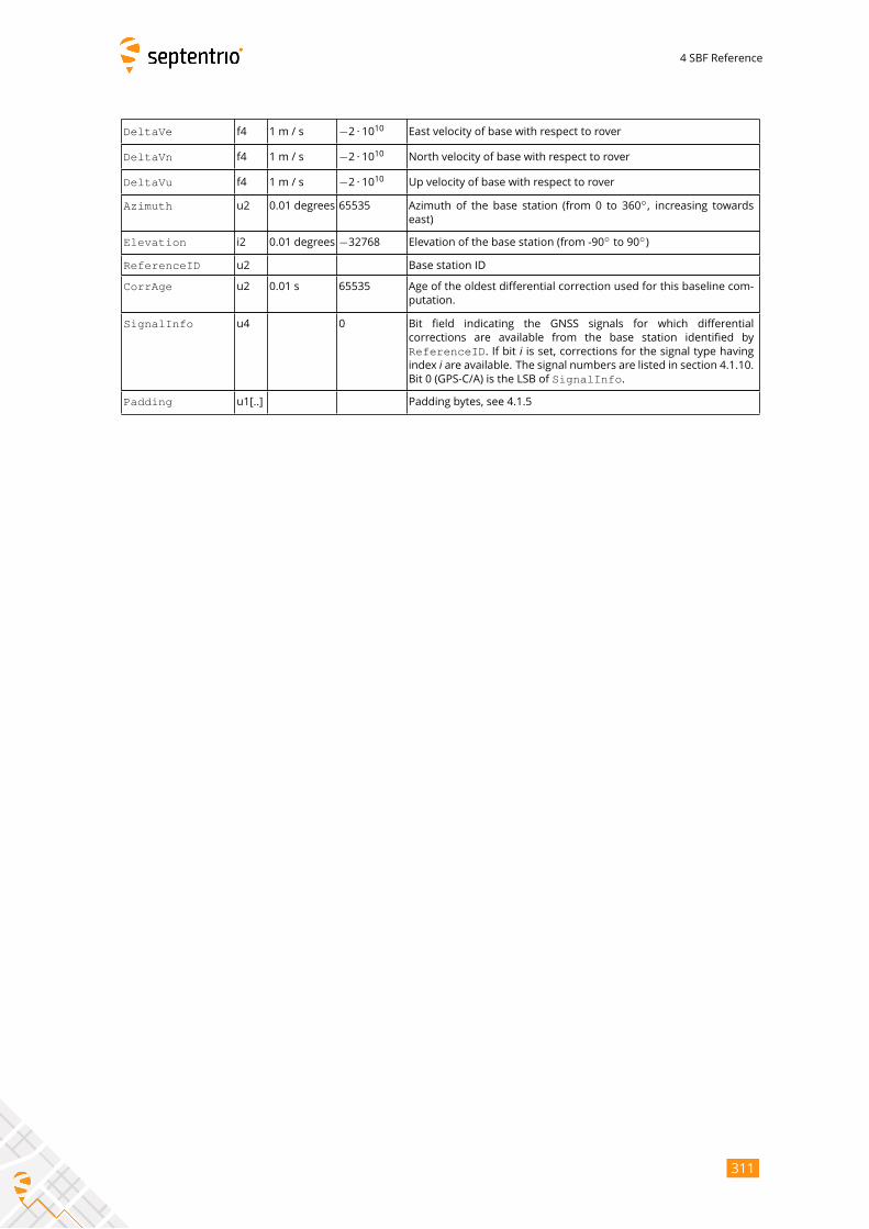
4 SBF Reference
DeltaVe f4 1 m / s −2 · 1010 East velocity of base with respect to rover
DeltaVn f4 1 m / s −2 · 1010 North velocity of base with respect to rover
DeltaVu f4 1 m / s −2 · 1010 Up velocity of base with respect to rover
Azimuth u2 0.01 degrees 65535 Azimuth of the base station (from 0 to 360◦, increasing towards
east)
Elevation i2 0.01 degrees −32768 Elevation of the base station (from -90◦to 90
◦)
ReferenceID u2 Base station ID
CorrAge u2 0.01 s 65535 Age of the oldest differential correction used for this baseline com-
putation.
SignalInfo u4 0 Bit field indicating the GNSS signals for which differential
corrections are available from the base station identified by
ReferenceID. If bit i is set, corrections for the signal type havingindex i are available. The signal numbers are listed in section 4.1.10.Bit 0 (GPS-C/A) is the LSB of SignalInfo.
Padding u1[..] Padding bytes, see 4.1.5
311
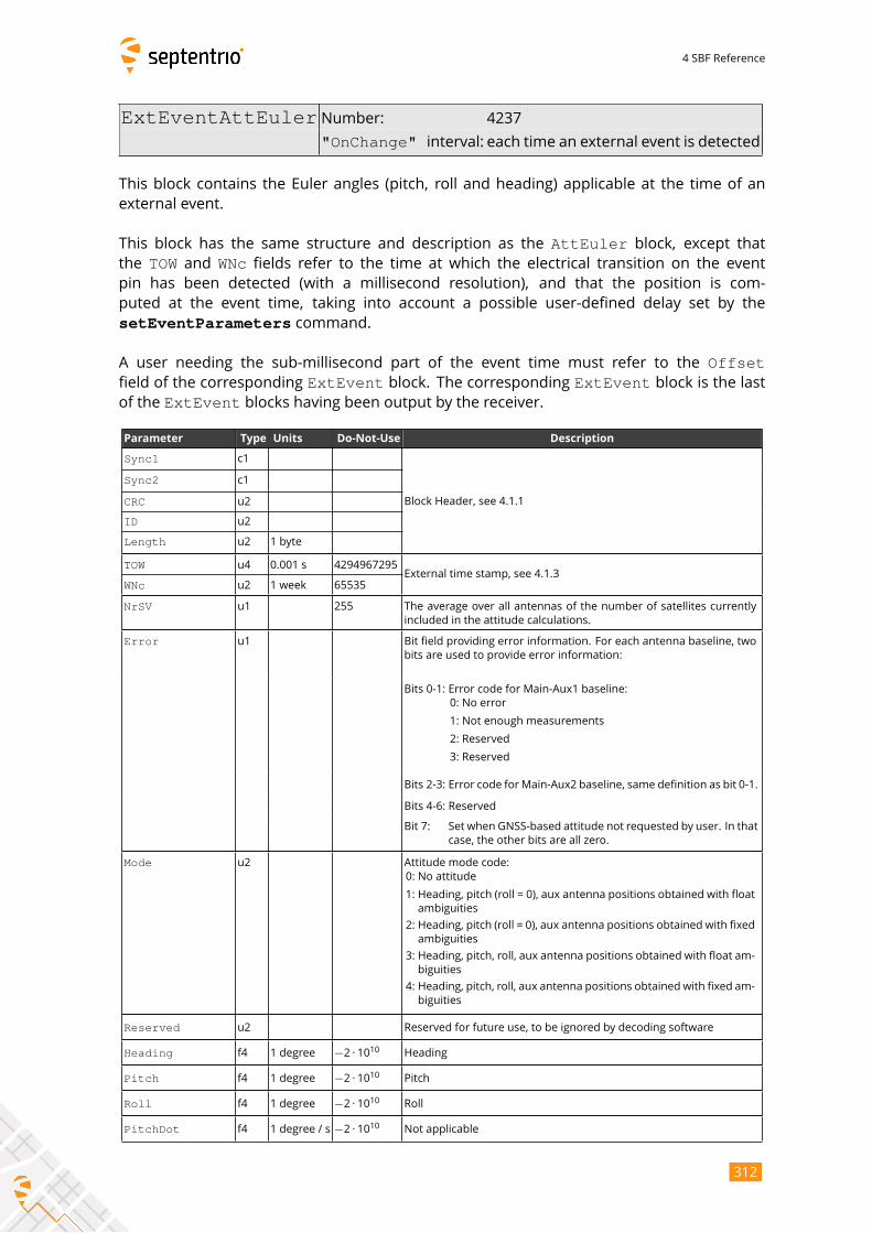
4 SBF Reference
ExtEventAttEuler Number: 4237
"OnChange" interval: each time an external event is detected
This block contains the Euler angles (pitch, roll and heading) applicable at the time of an
external event.
This block has the same structure and description as the AttEuler block, except thatthe TOW and WNc fields refer to the time at which the electrical transition on the event
pin has been detected (with a millisecond resolution), and that the position is com-
puted at the event time, taking into account a possible user-defined delay set by the
setEventParameters command.
A user needing the sub-millisecond part of the event time must refer to the Offsetfield of the corresponding ExtEvent block. The corresponding ExtEvent block is the lastof the ExtEvent blocks having been output by the receiver.
Parameter Type Units Do-Not-Use Description
Sync1 c1
Block Header, see 4.1.1
Sync2 c1
CRC u2
ID u2
Length u2 1 byte
TOW u4 0.001 s 4294967295External time stamp, see 4.1.3
WNc u2 1 week 65535
NrSV u1 255 The average over all antennas of the number of satellites currently
included in the attitude calculations.
Error u1 Bit field providing error information. For each antenna baseline, two
bits are used to provide error information:
Bits 0-1: Error code for Main-Aux1 baseline:
0: No error
1: Not enough measurements
2: Reserved
3: Reserved
Bits 2-3: Error code forMain-Aux2 baseline, same definition as bit 0-1.
Bits 4-6: Reserved
Bit 7: Set when GNSS-based attitude not requested by user. In that
case, the other bits are all zero.
Mode u2 Attitude mode code:
0: No attitude
1: Heading, pitch (roll = 0), aux antenna positions obtained with float
ambiguities
2: Heading, pitch (roll = 0), aux antenna positions obtained with fixed
ambiguities
3: Heading, pitch, roll, aux antenna positions obtained with float am-
biguities
4: Heading, pitch, roll, aux antenna positions obtained with fixed am-
biguities
Reserved u2 Reserved for future use, to be ignored by decoding software
Heading f4 1 degree −2 · 1010 Heading
Pitch f4 1 degree −2 · 1010 Pitch
Roll f4 1 degree −2 · 1010 Roll
PitchDot f4 1 degree / s −2 · 1010 Not applicable
312
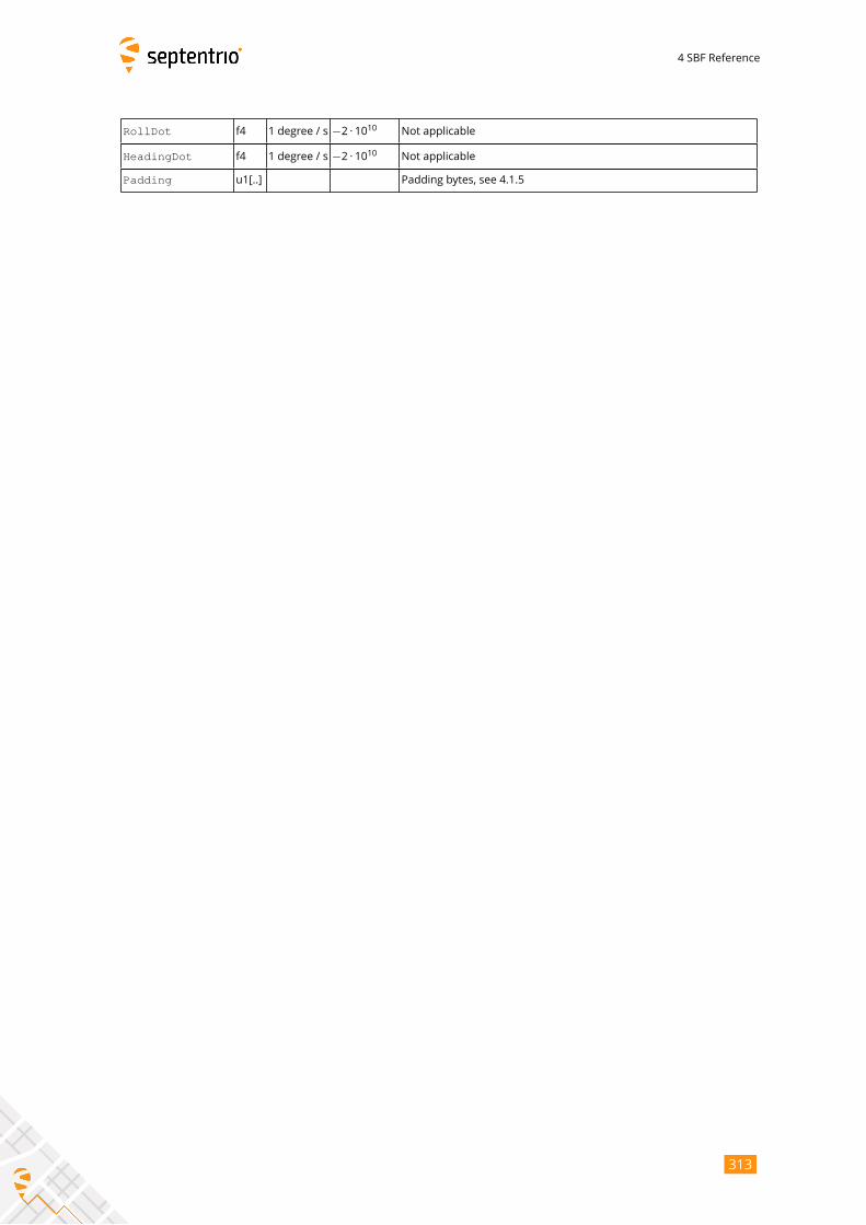
4 SBF Reference
RollDot f4 1 degree / s −2 · 1010 Not applicable
HeadingDot f4 1 degree / s −2 · 1010 Not applicable
Padding u1[..] Padding bytes, see 4.1.5
313
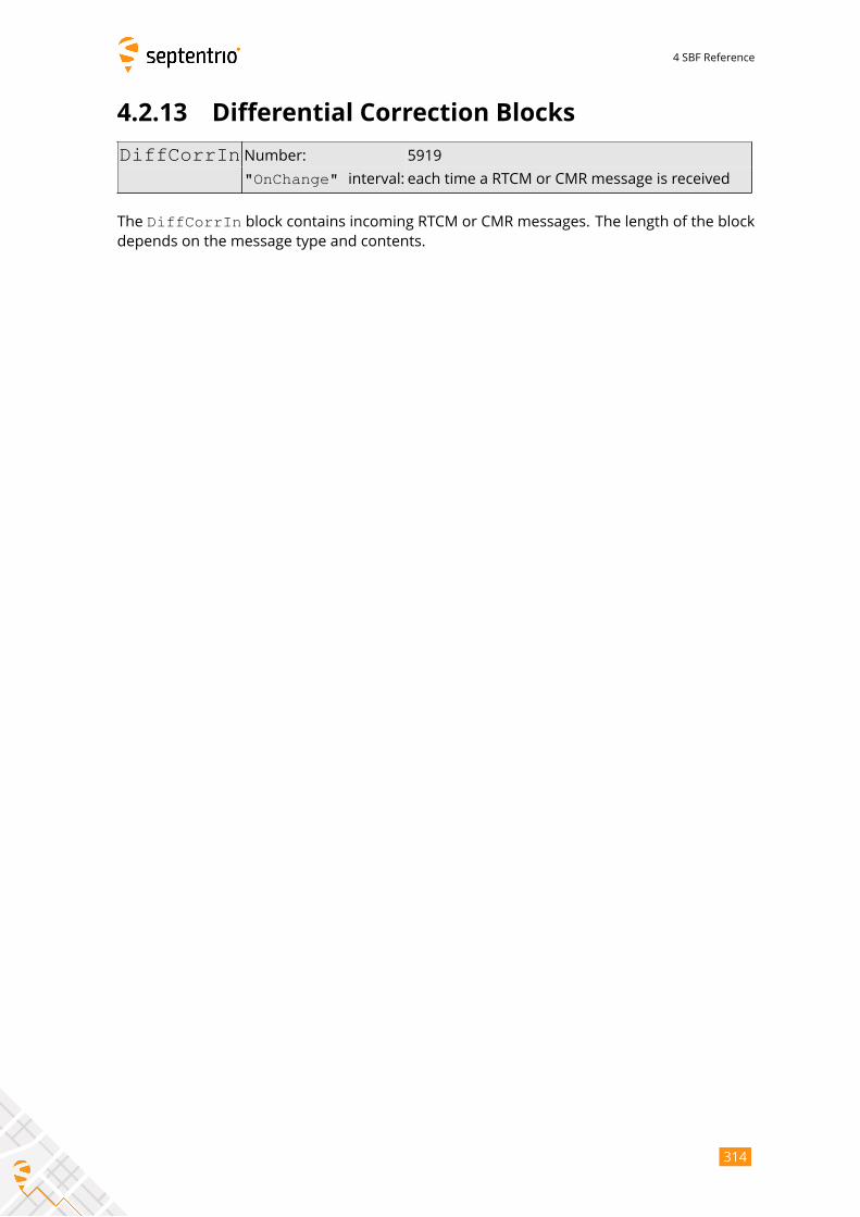
4 SBF Reference
4.2.13 Differential Correction Blocks
DiffCorrIn Number: 5919
"OnChange" interval: each time a RTCM or CMR message is received
The DiffCorrIn block contains incoming RTCM or CMR messages. The length of the blockdepends on the message type and contents.
314
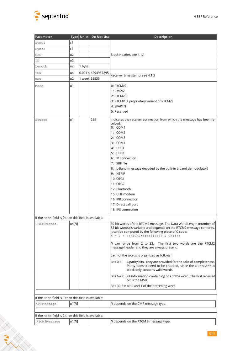
4 SBF Reference
Parameter Type Units Do-Not-Use Description
Sync1 c1
Block Header, see 4.1.1
Sync2 c1
CRC u2
ID u2
Length u2 1 byte
TOW u4 0.001 s 4294967295Receiver time stamp, see 4.1.3
WNc u2 1 week 65535
Mode u1 0: RTCMv2
1: CMRv2
2: RTCMv3
3: RTCMV (a proprietary variant of RTCM2)
4: SPARTN
5: Reserved
Source u1 255 Indicates the receiver connection from which the message has been re-
ceived:
0: COM1
1: COM2
2: COM3
3: COM4
4: USB1
5: USB2
6: IP connection
7: SBF file
8: L-Band (message decoded by the built-in L-band demodulator)
9: NTRIP
10: OTG1
11: OTG2
12: Bluetooth
15: UHF modem
16: IPR connection
17: Direct call port
18: IPS connection
If the Mode field is 0 then this field is available:
RTCM2Words u4[N] 30-bit words of the RTCM2 message. The Data Word Length (number of
32 bit words) is variable and depends on the RTCM2 message contents.
It can be computed by the following piece of C code:
N = 2 + ((RTCM2Words[1]»9) & 0x1f);
N can range from 2 to 33. The first two words are the RTCM2
message header and they are always present.
Each of the words is organized as follows:
Bits 0-5: 6 parity bits. They are provided for the sake of completeness.
Parity doesn’t need to be checked, since the DiffCorrInblock only contains valid words.
Bits 6-29: 24 information-containing bits of the word. The first received
bit is the MSB.
Bits 30-31: bit 0 and 1 of the preceding word
If the Mode field is 1 then this field is available:
CMRMessage u1[N] N depends on the CMR message type.
If the Mode field is 2 then this field is available:
RTCM3Message u1[N] N depends on the RTCM 3 message type.
315
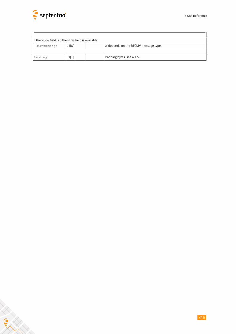
4 SBF Reference
If the Mode field is 3 then this field is available:
RTCMVMessage u1[N] N depends on the RTCMV message type.
Padding u1[..] Padding bytes, see 4.1.5
316
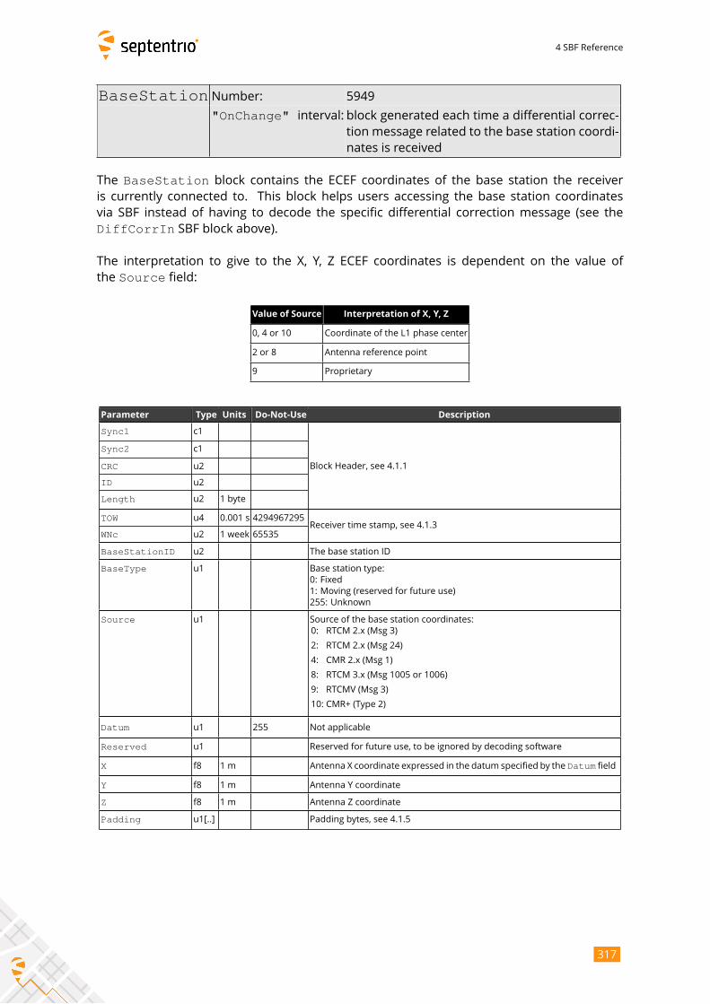
4 SBF Reference
BaseStation Number: 5949
"OnChange" interval: block generated each time a differential correc-tion message related to the base station coordi-
nates is received
The BaseStation block contains the ECEF coordinates of the base station the receiveris currently connected to. This block helps users accessing the base station coordinates
via SBF instead of having to decode the specific differential correction message (see the
DiffCorrIn SBF block above).
The interpretation to give to the X, Y, Z ECEF coordinates is dependent on the value of
the Source field:
Value of Source Interpretation of X, Y, Z
0, 4 or 10 Coordinate of the L1 phase center
2 or 8 Antenna reference point
9 Proprietary
Parameter Type Units Do-Not-Use Description
Sync1 c1
Block Header, see 4.1.1
Sync2 c1
CRC u2
ID u2
Length u2 1 byte
TOW u4 0.001 s 4294967295Receiver time stamp, see 4.1.3
WNc u2 1 week 65535
BaseStationID u2 The base station ID
BaseType u1 Base station type:
0: Fixed
1: Moving (reserved for future use)
255: Unknown
Source u1 Source of the base station coordinates:
0: RTCM 2.x (Msg 3)
2: RTCM 2.x (Msg 24)
4: CMR 2.x (Msg 1)
8: RTCM 3.x (Msg 1005 or 1006)
9: RTCMV (Msg 3)
10: CMR+ (Type 2)
Datum u1 255 Not applicable
Reserved u1 Reserved for future use, to be ignored by decoding software
X f8 1 m Antenna X coordinate expressed in the datum specified by the Datum field
Y f8 1 m Antenna Y coordinate
Z f8 1 m Antenna Z coordinate
Padding u1[..] Padding bytes, see 4.1.5
317
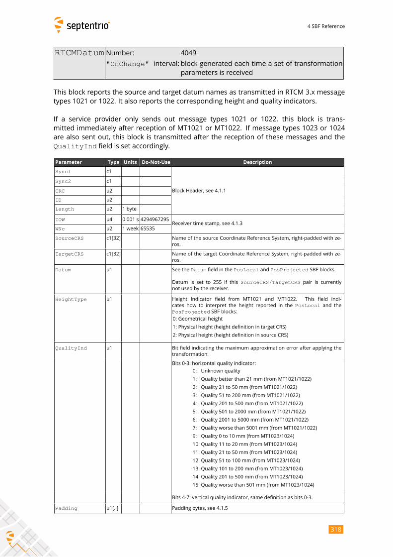
4 SBF Reference
RTCMDatum Number: 4049
"OnChange" interval: block generated each time a set of transformationparameters is received
This block reports the source and target datum names as transmitted in RTCM 3.x message
types 1021 or 1022. It also reports the corresponding height and quality indicators.
If a service provider only sends out message types 1021 or 1022, this block is trans-
mitted immediately after reception of MT1021 or MT1022. If message types 1023 or 1024
are also sent out, this block is transmitted after the reception of these messages and the
QualityInd field is set accordingly.
Parameter Type Units Do-Not-Use Description
Sync1 c1
Block Header, see 4.1.1
Sync2 c1
CRC u2
ID u2
Length u2 1 byte
TOW u4 0.001 s 4294967295Receiver time stamp, see 4.1.3
WNc u2 1 week 65535
SourceCRS c1[32] Name of the source Coordinate Reference System, right-padded with ze-
ros.
TargetCRS c1[32] Name of the target Coordinate Reference System, right-padded with ze-
ros.
Datum u1 See the Datum field in the PosLocal and PosProjected SBF blocks.
Datum is set to 255 if this SourceCRS/TargetCRS pair is currentlynot used by the receiver.
HeightType u1 Height Indicator field from MT1021 and MT1022. This field indi-
cates how to interpret the height reported in the PosLocal and thePosProjected SBF blocks:
0: Geometrical height
1: Physical height (height definition in target CRS)
2: Physical height (height definition in source CRS)
QualityInd u1 Bit field indicating the maximum approximation error after applying the
transformation:
Bits 0-3: horizontal quality indicator:
0: Unknown quality
1: Quality better than 21 mm (from MT1021/1022)
2: Quality 21 to 50 mm (from MT1021/1022)
3: Quality 51 to 200 mm (from MT1021/1022)
4: Quality 201 to 500 mm (from MT1021/1022)
5: Quality 501 to 2000 mm (from MT1021/1022)
6: Quality 2001 to 5000 mm (from MT1021/1022)
7: Quality worse than 5001 mm (from MT1021/1022)
9: Quality 0 to 10 mm (from MT1023/1024)
10: Quality 11 to 20 mm (from MT1023/1024)
11: Quality 21 to 50 mm (from MT1023/1024)
12: Quality 51 to 100 mm (from MT1023/1024)
13: Quality 101 to 200 mm (from MT1023/1024)
14: Quality 201 to 500 mm (from MT1023/1024)
15: Quality worse than 501 mm (from MT1023/1024)
Bits 4-7: vertical quality indicator, same definition as bits 0-3.
Padding u1[..] Padding bytes, see 4.1.5
318
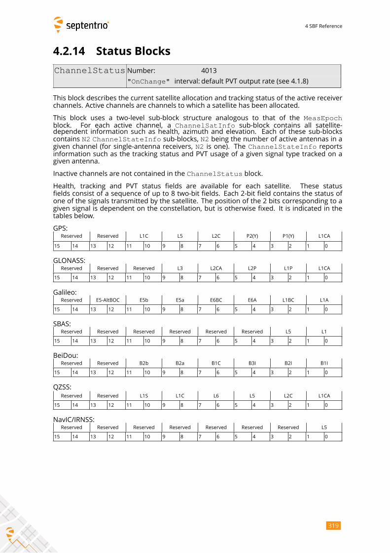
4 SBF Reference
4.2.14 Status Blocks
ChannelStatus Number: 4013
"OnChange" interval: default PVT output rate (see 4.1.8)
This block describes the current satellite allocation and tracking status of the active receiver
channels. Active channels are channels to which a satellite has been allocated.
This block uses a two-level sub-block structure analogous to that of the MeasEpochblock. For each active channel, a ChannelSatInfo sub-block contains all satellite-dependent information such as health, azimuth and elevation. Each of these sub-blocks
contains N2 ChannelStateInfo sub-blocks, N2 being the number of active antennas in agiven channel (for single-antenna receivers, N2 is one). The ChannelStateInfo reportsinformation such as the tracking status and PVT usage of a given signal type tracked on a
given antenna.
Inactive channels are not contained in the ChannelStatus block.
Health, tracking and PVT status fields are available for each satellite. These status
fields consist of a sequence of up to 8 two-bit fields. Each 2-bit field contains the status of
one of the signals transmitted by the satellite. The position of the 2 bits corresponding to a
given signal is dependent on the constellation, but is otherwise fixed. It is indicated in the
tables below.
GPS:
Reserved Reserved L1C L5 L2C P2(Y) P1(Y) L1CA
15 14 13 12 11 10 9 8 7 6 5 4 3 2 1 0
GLONASS:
Reserved Reserved Reserved L3 L2CA L2P L1P L1CA
15 14 13 12 11 10 9 8 7 6 5 4 3 2 1 0
Galileo:
Reserved E5-AltBOC E5b E5a E6BC E6A L1BC L1A
15 14 13 12 11 10 9 8 7 6 5 4 3 2 1 0
SBAS:
Reserved Reserved Reserved Reserved Reserved Reserved L5 L1
15 14 13 12 11 10 9 8 7 6 5 4 3 2 1 0
BeiDou:
Reserved Reserved B2b B2a B1C B3I B2I B1I
15 14 13 12 11 10 9 8 7 6 5 4 3 2 1 0
QZSS:
Reserved Reserved L1S L1C L6 L5 L2C L1CA
15 14 13 12 11 10 9 8 7 6 5 4 3 2 1 0
NavIC/IRNSS:
Reserved Reserved Reserved Reserved Reserved Reserved Reserved L5
15 14 13 12 11 10 9 8 7 6 5 4 3 2 1 0
319
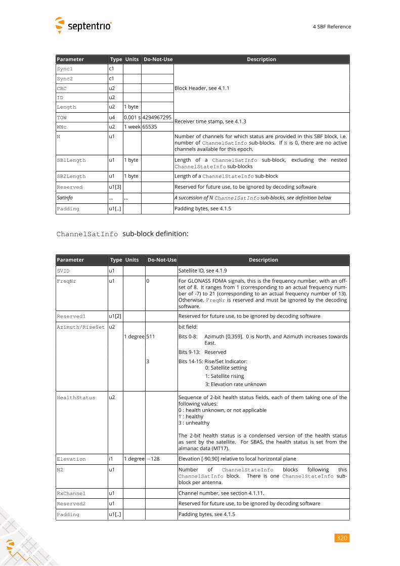
4 SBF Reference
Parameter Type Units Do-Not-Use Description
Sync1 c1
Block Header, see 4.1.1
Sync2 c1
CRC u2
ID u2
Length u2 1 byte
TOW u4 0.001 s 4294967295Receiver time stamp, see 4.1.3
WNc u2 1 week 65535
N u1 Number of channels for which status are provided in this SBF block, i.e.
number of ChannelSatInfo sub-blocks. If N is 0, there are no activechannels available for this epoch.
SB1Length u1 1 byte Length of a ChannelSatInfo sub-block, excluding the nested
ChannelStateInfo sub-blocks
SB2Length u1 1 byte Length of a ChannelStateInfo sub-block
Reserved u1[3] Reserved for future use, to be ignored by decoding software
SatInfo ... ... A succession of N ChannelSatInfo sub-blocks, see definition belowPadding u1[..] Padding bytes, see 4.1.5
ChannelSatInfo sub-block definition:
Parameter Type Units Do-Not-Use Description
SVID u1 Satellite ID, see 4.1.9
FreqNr u1 0 For GLONASS FDMA signals, this is the frequency number, with an off-
set of 8. It ranges from 1 (corresponding to an actual frequency num-
ber of -7) to 21 (corresponding to an actual frequency number of 13).
Otherwise, FreqNr is reserved and must be ignored by the decodingsoftware.
Reserved1 u1[2] Reserved for future use, to be ignored by decoding software
Azimuth/RiseSet u2 bit field:
1 degree 511 Bits 0-8: Azimuth [0,359]. 0 is North, and Azimuth increases towards
East.
Bits 9-13: Reserved
3 Bits 14-15: Rise/Set Indicator:
0: Satellite setting
1: Satellite rising
3: Elevation rate unknown
HealthStatus u2 Sequence of 2-bit health status fields, each of them taking one of the
following values:
0 : health unknown, or not applicable
1 : healthy
3 : unhealthy
The 2-bit health status is a condensed version of the health status
as sent by the satellite. For SBAS, the health status is set from the
almanac data (MT17).
Elevation i1 1 degree −128 Elevation [-90,90] relative to local horizontal plane
N2 u1 Number of ChannelStateInfo blocks following this
ChannelSatInfo block. There is one ChannelStateInfo sub-block per antenna.
RxChannel u1 Channel number, see section 4.1.11.
Reserved2 u1 Reserved for future use, to be ignored by decoding software
Padding u1[..] Padding bytes, see 4.1.5
320
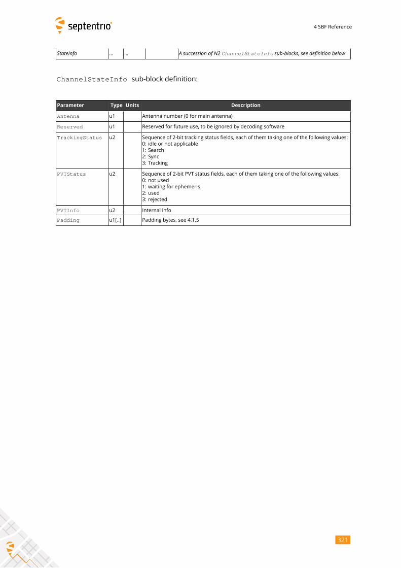
4 SBF Reference
StateInfo ... ... A succession of N2 ChannelStateInfo sub-blocks, see definition below
ChannelStateInfo sub-block definition:
Parameter Type Units Description
Antenna u1 Antenna number (0 for main antenna)
Reserved u1 Reserved for future use, to be ignored by decoding software
TrackingStatus u2 Sequence of 2-bit tracking status fields, each of them taking one of the following values:
0: idle or not applicable
1: Search
2: Sync
3: Tracking
PVTStatus u2 Sequence of 2-bit PVT status fields, each of them taking one of the following values:
0: not used
1: waiting for ephemeris
2: used
3: rejected
PVTInfo u2 Internal info
Padding u1[..] Padding bytes, see 4.1.5
321

4 SBF Reference
ReceiverStatus Number: 4014
"OnChange" interval: 1s
The ReceiverStatus block provides general information on the status of the re-
ceiver.
Parameter Type Units Do-Not-Use Description
Sync1 c1
Block Header, see 4.1.1
Sync2 c1
CRC u2
ID u2
Length u2 1 byte
TOW u4 0.001 s 4294967295Receiver time stamp, see 4.1.3
WNc u2 1 week 65535
CPULoad u1 1 % 255 Load on the receiver’s CPU. The load should stay below 80% in normal
operation. Higher loads might result in data loss.
ExtError u1 Bit field reporting external errors, i.e. errors detected in external data.
Upon detection of an error, the corresponding bit is set for a duration of
one second, and then resets.
Bit 0: SISERROR: set if a violation of the signal-in-space ICD has been
detected for at least one satellite while that satellite is reported
as healthy. Use the command "lif,SisError" for details.
Bit 1: DIFFCORRERROR: set when an anomaly has been detected
in an incoming differential correction stream, causing the re-
ceiver to fail to decode the corrections. Use the command
"lif,DiffCorrError" for details.
Bit 2: EXTSENSORERROR: set when a malfunction has been detected
on at least one of the external sensors connected to the re-
ceiver. Use the command "lif, ExtSensorError" for de-tails.
Bit 3: SETUPERROR: set when a configuration/setup error has been
detected. An example of such error is when a remote
NTRIP Caster is not reachable. Use the command "lif,SetupError" for details.
Bits 4-7: Reserved
UpTime u4 1 s Number of seconds elapsed since the start-up of the receiver, or since the
last reset.
322
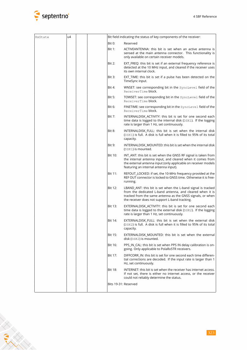
4 SBF Reference
RxState u4 Bit field indicating the status of key components of the receiver:
Bit 0: Reserved
Bit 1: ACTIVEANTENNA: this bit is set when an active antenna is
sensed at the main antenna connector. This functionality is
only available on certain receiver models.
Bit 2: EXT_FREQ: this bit is set if an external frequency reference is
detected at the 10 MHz input, and cleared if the receiver uses
its own internal clock.
Bit 3: EXT_TIME: this bit is set if a pulse has been detected on the
TimeSync input.
Bit 4: WNSET: see corresponding bit in the SyncLevel field of the
ReceiverTime block.
Bit 5: TOWSET: see corresponding bit in the SyncLevel field of the
ReceiverTime block.
Bit 6: FINETIME: see corresponding bit in the SyncLevel field of theReceiverTime block.
Bit 7: INTERNALDISK_ACTIVITY: this bit is set for one second each
time data is logged to the internal disk (DSK1). If the loggingrate is larger than 1 Hz, set continuously.
Bit 8: INTERNALDISK_FULL: this bit is set when the internal disk
(DSK1) is full. A disk is full when it is filled to 95% of its totalcapacity.
Bit 9: INTERNALDISK_MOUNTED: this bit is set when the internal disk
(DSK1) is mounted.
Bit 10: INT_ANT: this bit is set when the GNSS RF signal is taken from
the internal antenna input, and cleared when it comes from
the external antenna input (only applicable on receiver models
featuring an internal antenna input).
Bit 11: REFOUT_LOCKED: if set, the 10-MHz frequency provided at the
REF OUT connector is locked to GNSS time. Otherwise it is free-
running.
Bit 12: LBAND_ANT: this bit is set when the L-band signal is tracked
from the dedicated L-band antenna, and cleared when it is
tracked from the same antenna as the GNSS signals, or when
the receiver does not support L-band tracking.
Bit 13: EXTERNALDISK_ACTIVITY: this bit is set for one second each
time data is logged to the external disk (DSK2). If the loggingrate is larger than 1 Hz, set continuously.
Bit 14: EXTERNALDISK_FULL: this bit is set when the external disk
(DSK2) is full. A disk is full when it is filled to 95% of its totalcapacity.
Bit 15: EXTERNALDISK_MOUNTED: this bit is set when the external
disk (DSK2) is mounted.
Bit 16: PPS_IN_CAL: this bit is set when PPS IN delay calibration is on-
going. Only applicable to PolaRx5TR receivers.
Bit 17: DIFFCORR_IN: this bit is set for one second each time differen-
tial corrections are decoded. If the input rate is larger than 1
Hz, set continuously.
Bit 18: INTERNET: this bit is set when the receiver has internet access.
If not set, there is either no internet access, or the receiver
could not reliably determine the status.
Bits 19-31: Reserved
323
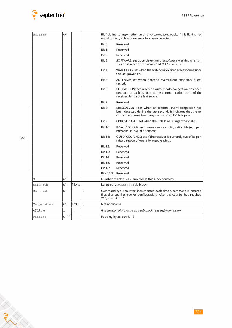
4 SBF Reference
RxError u4 Bit field indicating whether an error occurred previously. If this field is not
equal to zero, at least one error has been detected.
Bit 0: Reserved
Bit 1: Reserved
Bit 2: Reserved
Bit 3: SOFTWARE: set upon detection of a software warning or error.
This bit is reset by the command "lif, error".
Bit 4: WATCHDOG: set when thewatchdog expired at least once since
the last power-on.
Bit 5: ANTENNA: set when antenna overcurrent condition is de-
tected.
Bit 6: CONGESTION: set when an output data congestion has been
detected on at least one of the communication ports of the
receiver during the last second.
Bit 7: Reserved
Bit 8: MISSEDEVENT: set when an external event congestion has
been detected during the last second. It indicates that the re-
ceiver is receiving too many events on its EVENTx pins.
Bit 9: CPUOVERLOAD: set when the CPU load is larger than 90%.
Bit 10: INVALIDCONFIG: set if one or more configuration file (e.g. per-
missions) is invalid or absent.
Bit 11: OUTOFGEOFENCE: set if the receiver is currently out of its per-
mitted region of operation (geofencing).
Bit 12: Reserved
Bit 13: Reserved
Bit 14: Reserved
Bit 15: Reserved
Bit 16: Reserved
Rev 1
Bits 17-31: Reserved
N u1 Number of AGCState sub-blocks this block contains.
SBLength u1 1 byte Length of a AGCState sub-block.
CmdCount u1 0 Command cyclic counter, incremented each time a command is entered
that changes the receiver configuration. After the counter has reached
255, it resets to 1.
Temperature u1 1◦C 0 Not applicable.
AGCState ... ... A succession of N AGCState sub-blocks, see definition belowPadding u1[..] Padding bytes, see 4.1.5
324
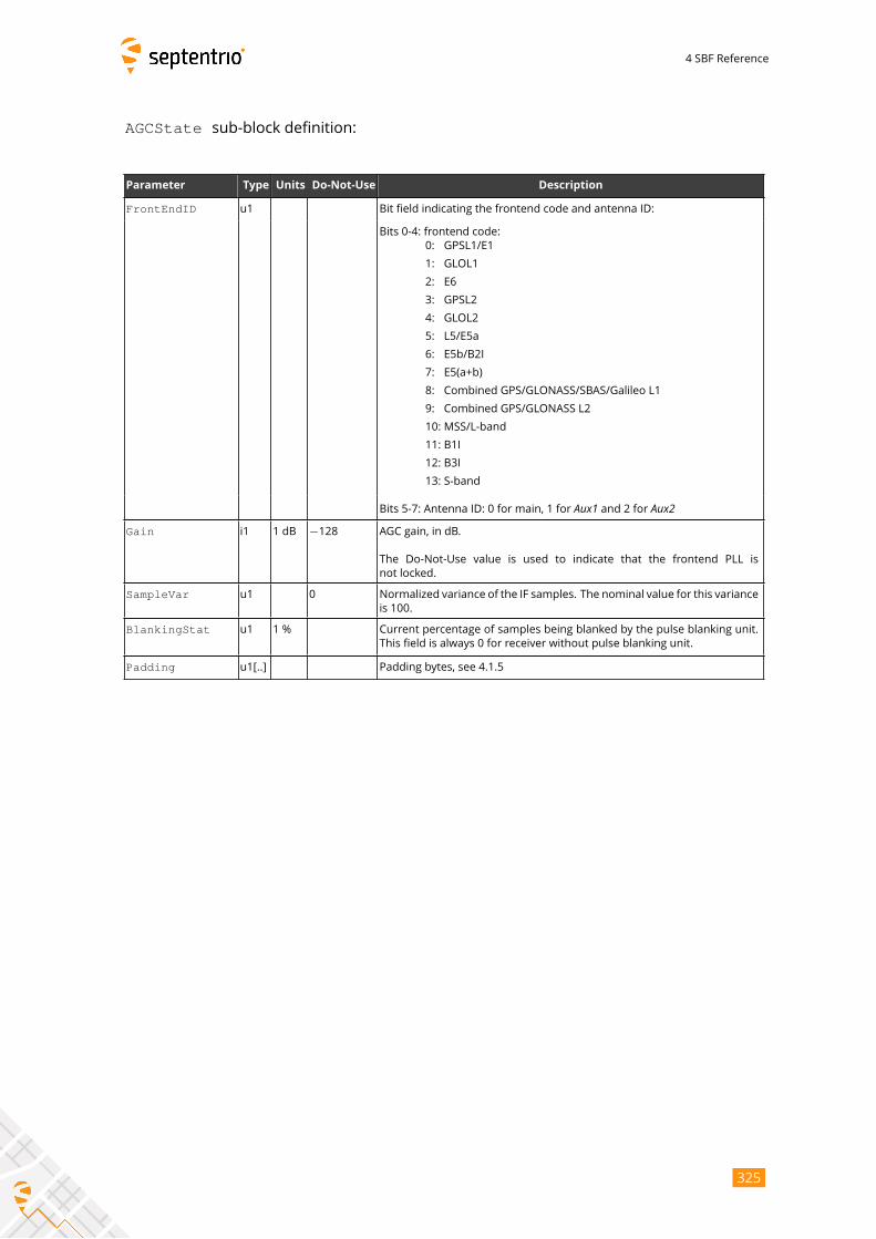
4 SBF Reference
AGCState sub-block definition:
Parameter Type Units Do-Not-Use Description
FrontEndID u1 Bit field indicating the frontend code and antenna ID:
Bits 0-4: frontend code:
0: GPSL1/E1
1: GLOL1
2: E6
3: GPSL2
4: GLOL2
5: L5/E5a
6: E5b/B2I
7: E5(a+b)
8: Combined GPS/GLONASS/SBAS/Galileo L1
9: Combined GPS/GLONASS L2
10: MSS/L-band
11: B1I
12: B3I
13: S-band
Bits 5-7: Antenna ID: 0 for main, 1 for Aux1 and 2 for Aux2Gain i1 1 dB −128 AGC gain, in dB.
The Do-Not-Use value is used to indicate that the frontend PLL is
not locked.
SampleVar u1 0 Normalized variance of the IF samples. The nominal value for this variance
is 100.
BlankingStat u1 1 % Current percentage of samples being blanked by the pulse blanking unit.
This field is always 0 for receiver without pulse blanking unit.
Padding u1[..] Padding bytes, see 4.1.5
325
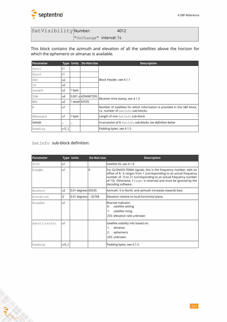
4 SBF Reference
SatVisibility Number: 4012
"OnChange" interval: 1s
This block contains the azimuth and elevation of all the satellites above the horizon for
which the ephemeris or almanac is available.
Parameter Type Units Do-Not-Use Description
Sync1 c1
Block Header, see 4.1.1
Sync2 c1
CRC u2
ID u2
Length u2 1 byte
TOW u4 0.001 s 4294967295Receiver time stamp, see 4.1.3
WNc u2 1 week 65535
N u1 Number of satellites for which information is provided in this SBF block,
i.e. number of SatInfo sub-blocks.
SBLength u1 1 byte Length of one SatInfo sub-block
SatInfo ... ... A succession of N SatInfo sub-blocks, see definition belowPadding u1[..] Padding bytes, see 4.1.5
SatInfo sub-block definition:
Parameter Type Units Do-Not-Use Description
SVID u1 Satellite ID, see 4.1.9
FreqNr u1 0 For GLONASS FDMA signals, this is the frequency number, with an
offset of 8. It ranges from 1 (corresponding to an actual frequency
number of -7) to 21 (corresponding to an actual frequency number
of 13). Otherwise, FreqNr is reserved and must be ignored by thedecoding software.
Azimuth u2 0.01 degrees 65535 Azimuth. 0 is North, and azimuth increases towards East.
Elevation i2 0.01 degrees −32768 Elevation relative to local horizontal plane.
RiseSet u1 Rise/set indicator:
0: satellite setting
1: satellite rising
255: elevation rate unknown
SatelliteInfo u1 Satellite visibility info based on:
1: almanac
2: ephemeris
255: unknown
Padding u1[..] Padding bytes, see 4.1.5
326
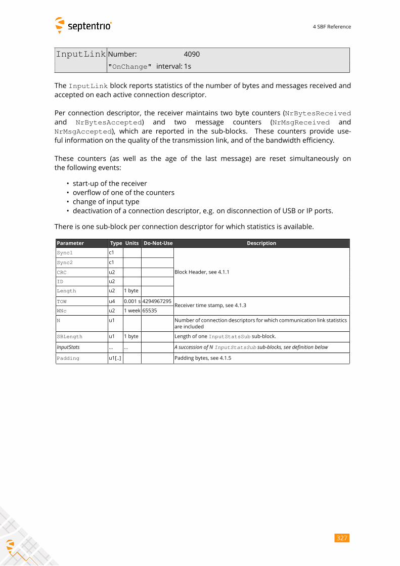
4 SBF Reference
InputLink Number: 4090
"OnChange" interval: 1s
The InputLink block reports statistics of the number of bytes and messages received andaccepted on each active connection descriptor.
Per connection descriptor, the receiver maintains two byte counters (NrBytesReceivedand NrBytesAccepted) and two message counters (NrMsgReceived and
NrMsgAccepted), which are reported in the sub-blocks. These counters provide use-ful information on the quality of the transmission link, and of the bandwidth efficiency.
These counters (as well as the age of the last message) are reset simultaneously on
the following events:
• start-up of the receiver
• overflow of one of the counters
• change of input type
• deactivation of a connection descriptor, e.g. on disconnection of USB or IP ports.
There is one sub-block per connection descriptor for which statistics is available.
Parameter Type Units Do-Not-Use Description
Sync1 c1
Block Header, see 4.1.1
Sync2 c1
CRC u2
ID u2
Length u2 1 byte
TOW u4 0.001 s 4294967295Receiver time stamp, see 4.1.3
WNc u2 1 week 65535
N u1 Number of connection descriptors for which communication link statistics
are included
SBLength u1 1 byte Length of one InputStatsSub sub-block.
InputStats ... ... A succession of N InputStatsSub sub-blocks, see definition belowPadding u1[..] Padding bytes, see 4.1.5
327
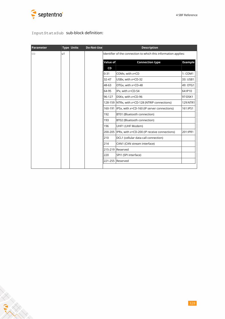
4 SBF Reference
InputStatsSub sub-block definition:
Parameter Type Units Do-Not-Use Description
CD u1 Identifier of the connection to which this information applies:
Value of Connection type Example
CD
0-31 COMx, with x=CD 1: COM1
32-47 USBx, with x=CD-32 33: USB1
48-63 OTGx, with x=CD-48 49: OTG1
64-95 IPx, with x=CD-54 64:IP10
96-127 DSKx, with x=CD-96 97:DSK1
128-159 NTRx, with x=CD-128 (NTRIP connections) 129:NTR1
160-191 IPSx, with x=CD-160 (IP server connections) 161:IPS1
192 BT01 (Bluetooth connection)
193 BT02 (Bluetooth connection)
196 UHF1 (UHF Modem)
200-205 IPRx, with x=CD-200 (IP receive connections) 201:IPR1
210 DCL1 (cellular data-call connection)
214 CAN1 (CAN stream interface)
215-219 Reserved
220 SPI1 (SPI interface)
221-255 Reserved
328
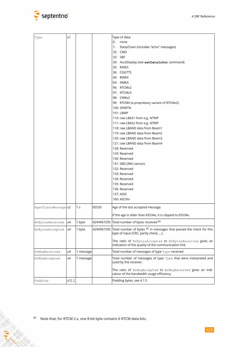
4 SBF Reference
Type u1 Type of data:
0: none
1: DaisyChain (includes "echo" messages)
32: CMD
33: SBF
34: AsciiDisplay (see setDataInOut command)
35: RINEX
36: CGGTTS
40: BINEX
64: NMEA
96: RTCMv2
97: RTCMv3
98: CMRv2
99: RTCMV (a proprietary variant of RTCMv2)
100: SPARTN
101: LBMP
110: raw LBAS1 from e.g. NTRIP
111: raw LBAS2 from e.g. NTRIP
118: raw LBAND data from Beam1
119: raw LBAND data from Beam2
120: raw LBAND data from Beam3
121: raw LBAND data from Beam4
128: Reserved
129: Reserved
130: Reserved
131: SBG (IMU sensor)
132: Reserved
133: Reserved
134: Reserved
135: Reserved
136: Reserved
137: ADIS
160: ASCIIIn
AgeOfLastMessage u2 1 s 65535 Age of the last accepted message.
If the age is older than 65534s, it is clipped to 65534s.
NrBytesReceived u4 1 byte 4294967295 Total number of bytes received(6)
NrBytesAccepted u4 1 byte 4294967295 Total number of bytes(6)in messages that passed the check for this
type of input (CRC, parity check, ...).
The ratio of NrBytesAccepted to NrBytesReceived gives anindication of the quality of the communication link.
NrMsgReceived u4 1 message Total number of messages of type Type received.
NrMsgAccepted u4 1 message Total number of messages of type Type that were interpreted andused by the receiver.
The ratio of NrMsgAccepted to NrMsgReceived gives an indi-cation of the bandwidth usage efficiency
Padding u1[..] Padding bytes, see 4.1.5
(6)Note that, for RTCM 2.x, one 8-bit byte contains 6 RTCM data bits.
329
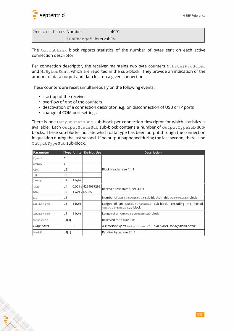
4 SBF Reference
OutputLink Number: 4091
"OnChange" interval: 1s
The OutputLink block reports statistics of the number of bytes sent on each activeconnection descriptor.
Per connection descriptor, the receiver maintains two byte counters NrBytesProducedand NrBytesSent, which are reported in the sub-block. They provide an indication of theamount of data output and data lost on a given connection.
These counters are reset simultaneously on the following events:
• start-up of the receiver
• overflow of one of the counters
• deactivation of a connection descriptor, e.g. on disconnection of USB or IP ports
• change of COM port settings.
There is one OutputStatsSub sub-block per connection descriptor for which statistics isavailable. Each OutputStatsSub sub-block contains a number of OutputTypeSub sub-blocks. These sub-blocks indicate which data type has been output through the connection
in question during the last second. If no output happened during the last second, there is no
OutputTypeSub sub-block.
Parameter Type Units Do-Not-Use Description
Sync1 c1
Block Header, see 4.1.1
Sync2 c1
CRC u2
ID u2
Length u2 1 byte
TOW u4 0.001 s 4294967295Receiver time stamp, see 4.1.3
WNc u2 1 week 65535
N1 u1 Number of OutputStatsSub sub-blocks in this OutputLink block.
SB1Length u1 1 byte Length of an OutputStatsSub sub-block, excluding the nested
OutputTypeSub sub-block
SB2Length u1 1 byte Length of an OutputTypeSub sub-block
Reserved u1[3] Reserved for future use
OutputStats ... ... A succession of N1 OutputStatsSub sub-blocks, see definition belowPadding u1[..] Padding bytes, see 4.1.5
330
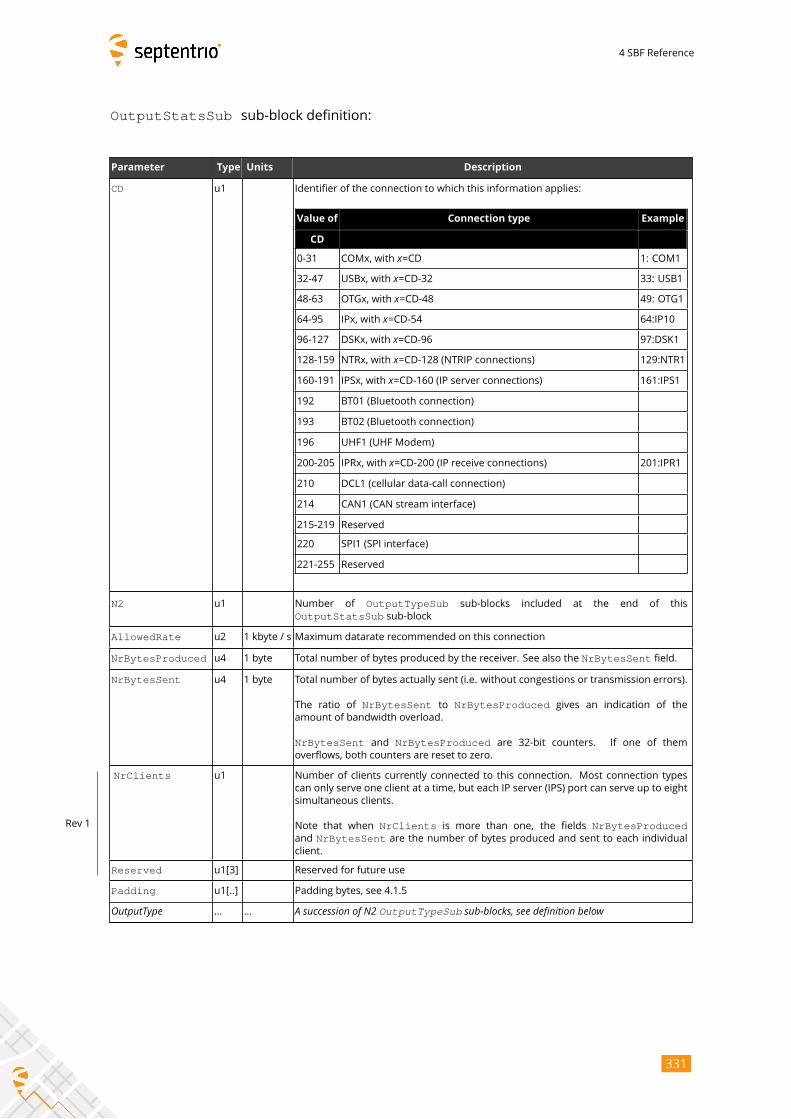
4 SBF Reference
OutputStatsSub sub-block definition:
Parameter Type Units Description
CD u1 Identifier of the connection to which this information applies:
Value of Connection type Example
CD
0-31 COMx, with x=CD 1: COM1
32-47 USBx, with x=CD-32 33: USB1
48-63 OTGx, with x=CD-48 49: OTG1
64-95 IPx, with x=CD-54 64:IP10
96-127 DSKx, with x=CD-96 97:DSK1
128-159 NTRx, with x=CD-128 (NTRIP connections) 129:NTR1
160-191 IPSx, with x=CD-160 (IP server connections) 161:IPS1
192 BT01 (Bluetooth connection)
193 BT02 (Bluetooth connection)
196 UHF1 (UHF Modem)
200-205 IPRx, with x=CD-200 (IP receive connections) 201:IPR1
210 DCL1 (cellular data-call connection)
214 CAN1 (CAN stream interface)
215-219 Reserved
220 SPI1 (SPI interface)
221-255 Reserved
N2 u1 Number of OutputTypeSub sub-blocks included at the end of this
OutputStatsSub sub-block
AllowedRate u2 1 kbyte / s Maximum datarate recommended on this connection
NrBytesProduced u4 1 byte Total number of bytes produced by the receiver. See also the NrBytesSent field.
NrBytesSent u4 1 byte Total number of bytes actually sent (i.e. without congestions or transmission errors).
The ratio of NrBytesSent to NrBytesProduced gives an indication of theamount of bandwidth overload.
NrBytesSent and NrBytesProduced are 32-bit counters. If one of them
overflows, both counters are reset to zero.
NrClients u1 Number of clients currently connected to this connection. Most connection types
can only serve one client at a time, but each IP server (IPS) port can serve up to eight
simultaneous clients.
Note that when NrClients is more than one, the fields NrBytesProducedand NrBytesSent are the number of bytes produced and sent to each individualclient.
Reserved u1[3] Reserved for future use
Rev 1
Padding u1[..] Padding bytes, see 4.1.5
OutputType ... ... A succession of N2 OutputTypeSub sub-blocks, see definition below
331
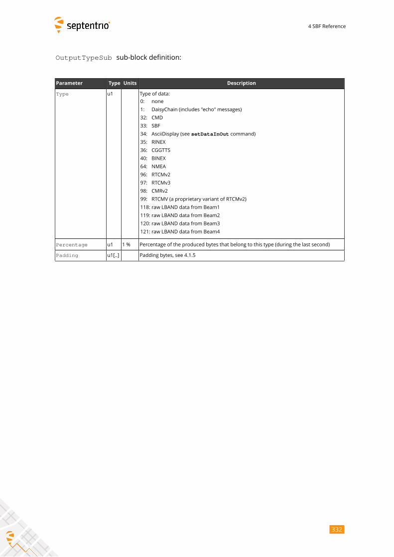
4 SBF Reference
OutputTypeSub sub-block definition:
Parameter Type Units Description
Type u1 Type of data:
0: none
1: DaisyChain (includes "echo" messages)
32: CMD
33: SBF
34: AsciiDisplay (see setDataInOut command)
35: RINEX
36: CGGTTS
40: BINEX
64: NMEA
96: RTCMv2
97: RTCMv3
98: CMRv2
99: RTCMV (a proprietary variant of RTCMv2)
118: raw LBAND data from Beam1
119: raw LBAND data from Beam2
120: raw LBAND data from Beam3
121: raw LBAND data from Beam4
Percentage u1 1 % Percentage of the produced bytes that belong to this type (during the last second)
Padding u1[..] Padding bytes, see 4.1.5
332
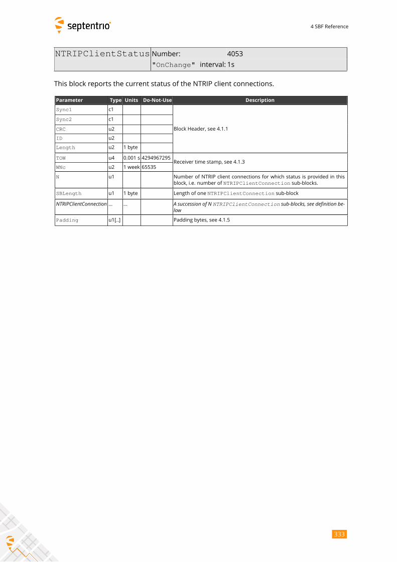
4 SBF Reference
NTRIPClientStatus Number: 4053
"OnChange" interval: 1s
This block reports the current status of the NTRIP client connections.
Parameter Type Units Do-Not-Use Description
Sync1 c1
Block Header, see 4.1.1
Sync2 c1
CRC u2
ID u2
Length u2 1 byte
TOW u4 0.001 s 4294967295Receiver time stamp, see 4.1.3
WNc u2 1 week 65535
N u1 Number of NTRIP client connections for which status is provided in this
block, i.e. number of NTRIPClientConnection sub-blocks.
SBLength u1 1 byte Length of one NTRIPClientConnection sub-block
NTRIPClientConnection ... ... A succession of N NTRIPClientConnection sub-blocks, see definition be-lowPadding u1[..] Padding bytes, see 4.1.5
333
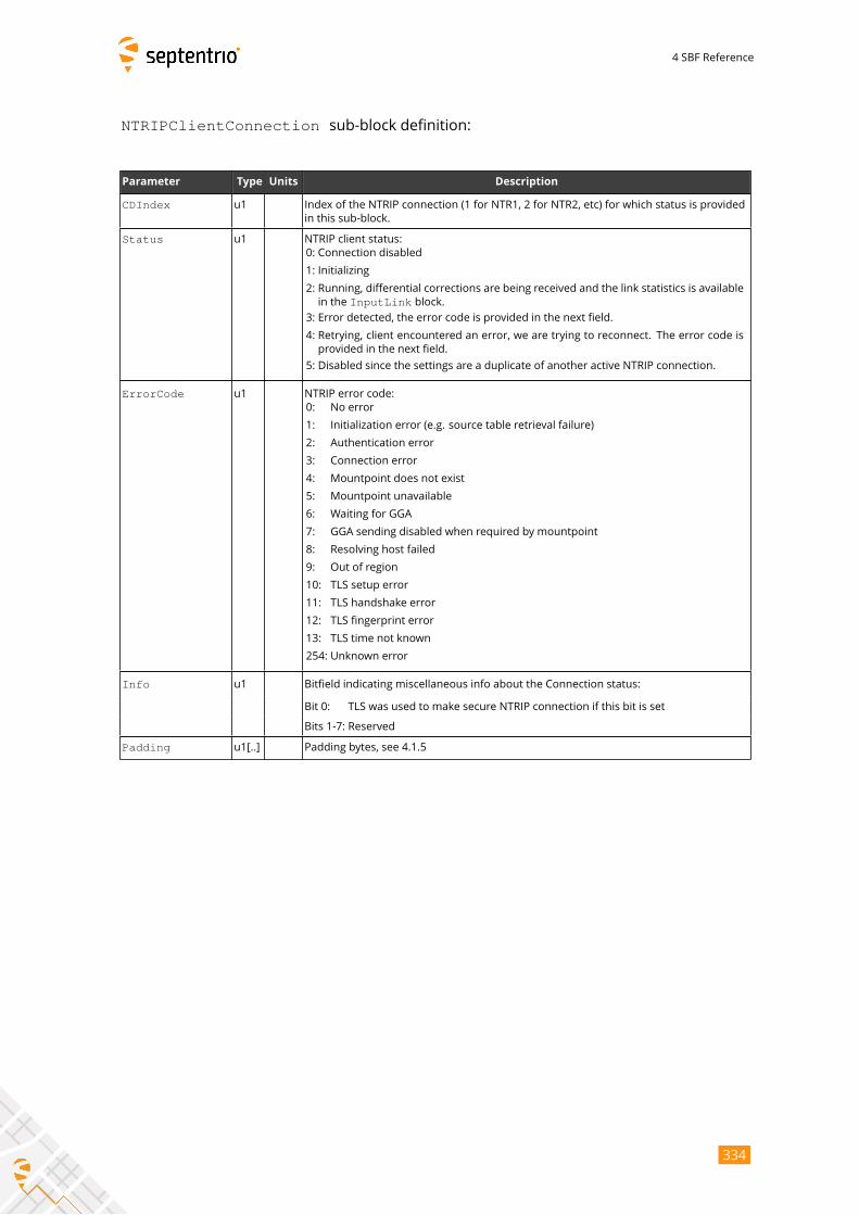
4 SBF Reference
NTRIPClientConnection sub-block definition:
Parameter Type Units Description
CDIndex u1 Index of the NTRIP connection (1 for NTR1, 2 for NTR2, etc) for which status is provided
in this sub-block.
Status u1 NTRIP client status:
0: Connection disabled
1: Initializing
2: Running, differential corrections are being received and the link statistics is available
in the InputLink block.
3: Error detected, the error code is provided in the next field.
4: Retrying, client encountered an error, we are trying to reconnect. The error code is
provided in the next field.
5: Disabled since the settings are a duplicate of another active NTRIP connection.
ErrorCode u1 NTRIP error code:
0: No error
1: Initialization error (e.g. source table retrieval failure)
2: Authentication error
3: Connection error
4: Mountpoint does not exist
5: Mountpoint unavailable
6: Waiting for GGA
7: GGA sending disabled when required by mountpoint
8: Resolving host failed
9: Out of region
10: TLS setup error
11: TLS handshake error
12: TLS fingerprint error
13: TLS time not known
254: Unknown error
Info u1 Bitfield indicating miscellaneous info about the Connection status:
Bit 0: TLS was used to make secure NTRIP connection if this bit is set
Bits 1-7: Reserved
Padding u1[..] Padding bytes, see 4.1.5
334
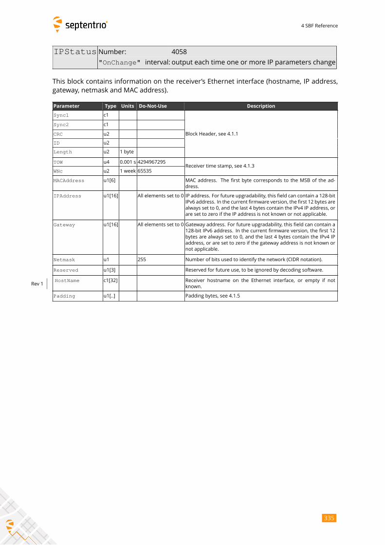
4 SBF Reference
IPStatus Number: 4058
"OnChange" interval: output each time one or more IP parameters change
This block contains information on the receiver’s Ethernet interface (hostname, IP address,
gateway, netmask and MAC address).
Parameter Type Units Do-Not-Use Description
Sync1 c1
Block Header, see 4.1.1
Sync2 c1
CRC u2
ID u2
Length u2 1 byte
TOW u4 0.001 s 4294967295Receiver time stamp, see 4.1.3
WNc u2 1 week 65535
MACAddress u1[6] MAC address. The first byte corresponds to the MSB of the ad-
dress.
IPAddress u1[16] All elements set to 0 IP address. For future upgradability, this field can contain a 128-bit
IPv6 address. In the current firmware version, the first 12 bytes are
always set to 0, and the last 4 bytes contain the IPv4 IP address, or
are set to zero if the IP address is not known or not applicable.
Gateway u1[16] All elements set to 0 Gateway address. For future upgradability, this field can contain a
128-bit IPv6 address. In the current firmware version, the first 12
bytes are always set to 0, and the last 4 bytes contain the IPv4 IP
address, or are set to zero if the gateway address is not known or
not applicable.
Netmask u1 255 Number of bits used to identify the network (CIDR notation).
Reserved u1[3] Reserved for future use, to be ignored by decoding software.
HostName c1[32] Receiver hostname on the Ethernet interface, or empty if not
known.Rev 1
Padding u1[..] Padding bytes, see 4.1.5
335
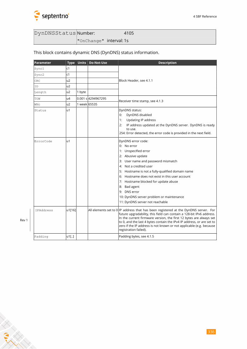
4 SBF Reference
DynDNSStatus Number: 4105
"OnChange" interval: 1s
This block contains dynamic DNS (DynDNS) status information.
Parameter Type Units Do-Not-Use Description
Sync1 c1
Block Header, see 4.1.1
Sync2 c1
CRC u2
ID u2
Length u2 1 byte
TOW u4 0.001 s 4294967295Receiver time stamp, see 4.1.3
WNc u2 1 week 65535
Status u1 DynDNS status:
0: DynDNS disabled
1: Updating IP address
2: IP address updated at the DynDNS server. DynDNS is ready
to use.
254: Error detected, the error code is provided in the next field.
ErrorCode u1 DynDNS error code:
0: No error
1: Unspecified error
2: Abusive update
3: User name and password mismatch
4: Not a credited user
5: Hostname is not a fully-qualified domain name
6: Hostname does not exist in this user account
7: Hostname blocked for update abuse
8: Bad agent
9: DNS error
10: DynDNS server problem or maintenance
11: DynDNS server not reachable
IPAddress u1[16] All elements set to 0 IP address that has been registered at the DynDNS server. For
future upgradability, this field can contain a 128-bit IPv6 address.
In the current firmware version, the first 12 bytes are always set
to 0, and the last 4 bytes contain the IPv4 IP address, or are set to
zero if the IP address is not known or not applicable (e.g. because
registration failed).
Rev 1
Padding u1[..] Padding bytes, see 4.1.5
336
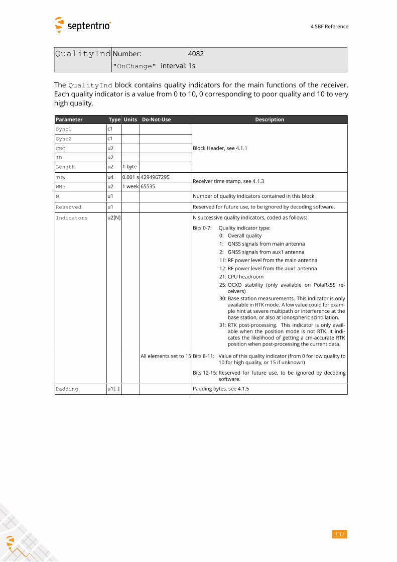
4 SBF Reference
QualityInd Number: 4082
"OnChange" interval: 1s
The QualityInd block contains quality indicators for the main functions of the receiver.Each quality indicator is a value from 0 to 10, 0 corresponding to poor quality and 10 to very
high quality.
Parameter Type Units Do-Not-Use Description
Sync1 c1
Block Header, see 4.1.1
Sync2 c1
CRC u2
ID u2
Length u2 1 byte
TOW u4 0.001 s 4294967295Receiver time stamp, see 4.1.3
WNc u2 1 week 65535
N u1 Number of quality indicators contained in this block
Reserved u1 Reserved for future use, to be ignored by decoding software.
Indicators u2[N] N successive quality indicators, coded as follows:
Bits 0-7: Quality indicator type:
0: Overall quality
1: GNSS signals from main antenna
2: GNSS signals from aux1 antenna
11: RF power level from the main antenna
12: RF power level from the aux1 antenna
21: CPU headroom
25: OCXO stability (only available on PolaRx5S re-
ceivers)
30: Base station measurements. This indicator is only
available in RTKmode. A low value could for exam-
ple hint at severe multipath or interference at the
base station, or also at ionospheric scintillation.
31: RTK post-processing. This indicator is only avail-
able when the position mode is not RTK. It indi-
cates the likelihood of getting a cm-accurate RTK
position when post-processing the current data.
All elements set to 15 Bits 8-11: Value of this quality indicator (from 0 for low quality to
10 for high quality, or 15 if unknown)
Bits 12-15: Reserved for future use, to be ignored by decoding
software.
Padding u1[..] Padding bytes, see 4.1.5
337
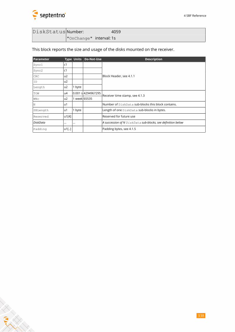
4 SBF Reference
DiskStatus Number: 4059
"OnChange" interval: 1s
This block reports the size and usage of the disks mounted on the receiver.
Parameter Type Units Do-Not-Use Description
Sync1 c1
Block Header, see 4.1.1
Sync2 c1
CRC u2
ID u2
Length u2 1 byte
TOW u4 0.001 s 4294967295Receiver time stamp, see 4.1.3
WNc u2 1 week 65535
N u1 Number of DiskData sub-blocks this block contains.
SBLength u1 1 byte Length of one DiskData sub-blocks in bytes.
Reserved u1[4] Reserved for future use
DiskData ... ... A succession of N DiskData sub-blocks, see definition belowPadding u1[..] Padding bytes, see 4.1.5
338
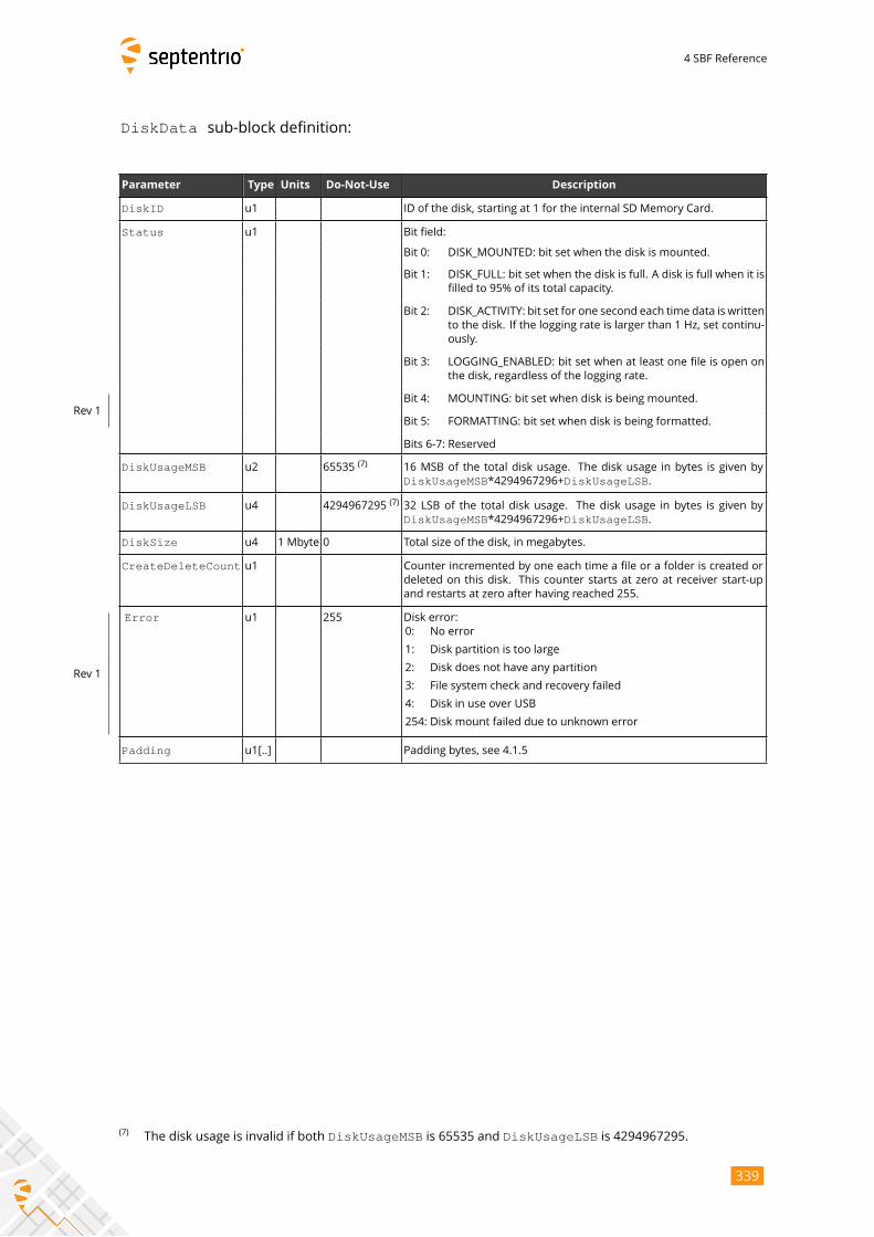
4 SBF Reference
DiskData sub-block definition:
Parameter Type Units Do-Not-Use Description
DiskID u1 ID of the disk, starting at 1 for the internal SD Memory Card.
Status u1 Bit field:
Bit 0: DISK_MOUNTED: bit set when the disk is mounted.
Bit 1: DISK_FULL: bit set when the disk is full. A disk is full when it is
filled to 95% of its total capacity.
Bit 2: DISK_ACTIVITY: bit set for one second each time data is written
to the disk. If the logging rate is larger than 1 Hz, set continu-
ously.
Bit 3: LOGGING_ENABLED: bit set when at least one file is open on
the disk, regardless of the logging rate.
Bit 4: MOUNTING: bit set when disk is being mounted.
Bit 5: FORMATTING: bit set when disk is being formatted.
Rev 1
Bits 6-7: Reserved
DiskUsageMSB u2 65535(7)
16 MSB of the total disk usage. The disk usage in bytes is given by
DiskUsageMSB*4294967296+DiskUsageLSB.
DiskUsageLSB u4 4294967295(7)32 LSB of the total disk usage. The disk usage in bytes is given by
DiskUsageMSB*4294967296+DiskUsageLSB.
DiskSize u4 1 Mbyte 0 Total size of the disk, in megabytes.
CreateDeleteCount u1 Counter incremented by one each time a file or a folder is created or
deleted on this disk. This counter starts at zero at receiver start-up
and restarts at zero after having reached 255.
Error u1 255 Disk error:
0: No error
1: Disk partition is too large
2: Disk does not have any partition
3: File system check and recovery failed
4: Disk in use over USB
254: Disk mount failed due to unknown error
Rev 1
Padding u1[..] Padding bytes, see 4.1.5
(7)The disk usage is invalid if both DiskUsageMSB is 65535 and DiskUsageLSB is 4294967295.
339
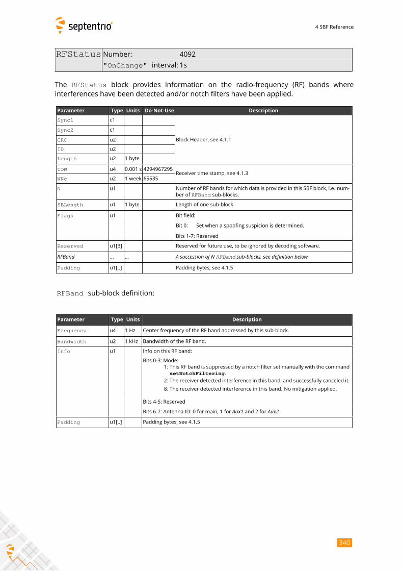
4 SBF Reference
RFStatus Number: 4092
"OnChange" interval: 1s
The RFStatus block provides information on the radio-frequency (RF) bands whereinterferences have been detected and/or notch filters have been applied.
Parameter Type Units Do-Not-Use Description
Sync1 c1
Block Header, see 4.1.1
Sync2 c1
CRC u2
ID u2
Length u2 1 byte
TOW u4 0.001 s 4294967295Receiver time stamp, see 4.1.3
WNc u2 1 week 65535
N u1 Number of RF bands for which data is provided in this SBF block, i.e. num-
ber of RFBand sub-blocks.
SBLength u1 1 byte Length of one sub-block
Flags u1 Bit field:
Bit 0: Set when a spoofing suspicion is determined.
Bits 1-7: Reserved
Reserved u1[3] Reserved for future use, to be ignored by decoding software.
RFBand ... ... A succession of N RFBand sub-blocks, see definition belowPadding u1[..] Padding bytes, see 4.1.5
RFBand sub-block definition:
Parameter Type Units Description
Frequency u4 1 Hz Center frequency of the RF band addressed by this sub-block.
Bandwidth u2 1 kHz Bandwidth of the RF band.
Info u1 Info on this RF band:
Bits 0-3: Mode:
1: This RF band is suppressed by a notch filter set manually with the command
setNotchFiltering.2: The receiver detected interference in this band, and successfully canceled it.
8: The receiver detected interference in this band. No mitigation applied.
Bits 4-5: Reserved
Bits 6-7: Antenna ID: 0 for main, 1 for Aux1 and 2 for Aux2Padding u1[..] Padding bytes, see 4.1.5
340
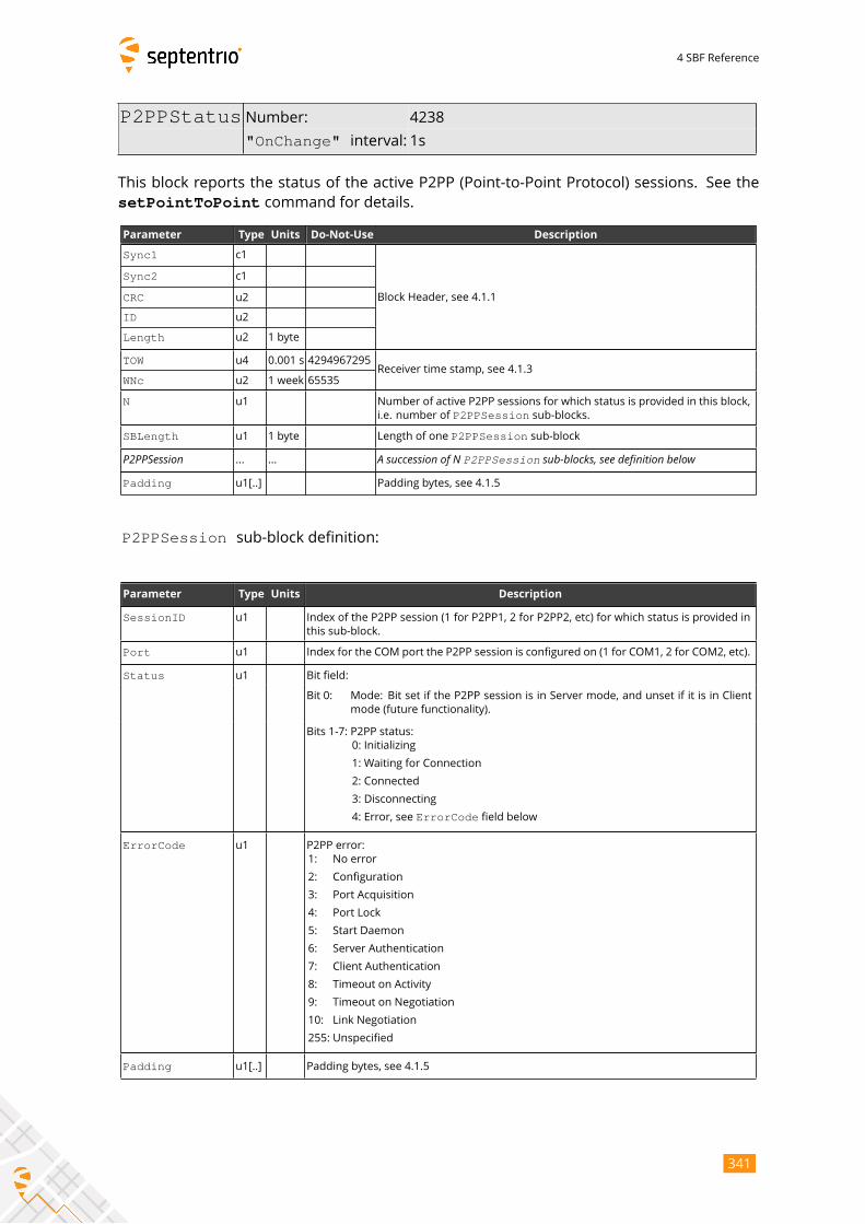
4 SBF Reference
P2PPStatus Number: 4238
"OnChange" interval: 1s
This block reports the status of the active P2PP (Point-to-Point Protocol) sessions. See the
setPointToPoint command for details.
Parameter Type Units Do-Not-Use Description
Sync1 c1
Block Header, see 4.1.1
Sync2 c1
CRC u2
ID u2
Length u2 1 byte
TOW u4 0.001 s 4294967295Receiver time stamp, see 4.1.3
WNc u2 1 week 65535
N u1 Number of active P2PP sessions for which status is provided in this block,
i.e. number of P2PPSession sub-blocks.
SBLength u1 1 byte Length of one P2PPSession sub-block
P2PPSession ... ... A succession of N P2PPSession sub-blocks, see definition belowPadding u1[..] Padding bytes, see 4.1.5
P2PPSession sub-block definition:
Parameter Type Units Description
SessionID u1 Index of the P2PP session (1 for P2PP1, 2 for P2PP2, etc) for which status is provided in
this sub-block.
Port u1 Index for the COM port the P2PP session is configured on (1 for COM1, 2 for COM2, etc).
Status u1 Bit field:
Bit 0: Mode: Bit set if the P2PP session is in Server mode, and unset if it is in Client
mode (future functionality).
Bits 1-7: P2PP status:
0: Initializing
1: Waiting for Connection
2: Connected
3: Disconnecting
4: Error, see ErrorCode field below
ErrorCode u1 P2PP error:
1: No error
2: Configuration
3: Port Acquisition
4: Port Lock
5: Start Daemon
6: Server Authentication
7: Client Authentication
8: Timeout on Activity
9: Timeout on Negotiation
10: Link Negotiation
255: Unspecified
Padding u1[..] Padding bytes, see 4.1.5
341

4 SBF Reference
4.2.15 Miscellaneous Blocks
ReceiverSetup Number: 5902
"OnChange" interval: Block generated each time a user-commandis entered to change one or more val-
ues in the block (e.g. when entering the
setMarkerParameters command)
The ReceiverSetup block contains parameters related to the receiver and its installation.When generating RINEX files, this block defines the RINEX file name and the contents of the
header.
For all fields containing a string, if the length of the string is lower than the size of the
corresponding field, the unused bytes are set to zero.
342
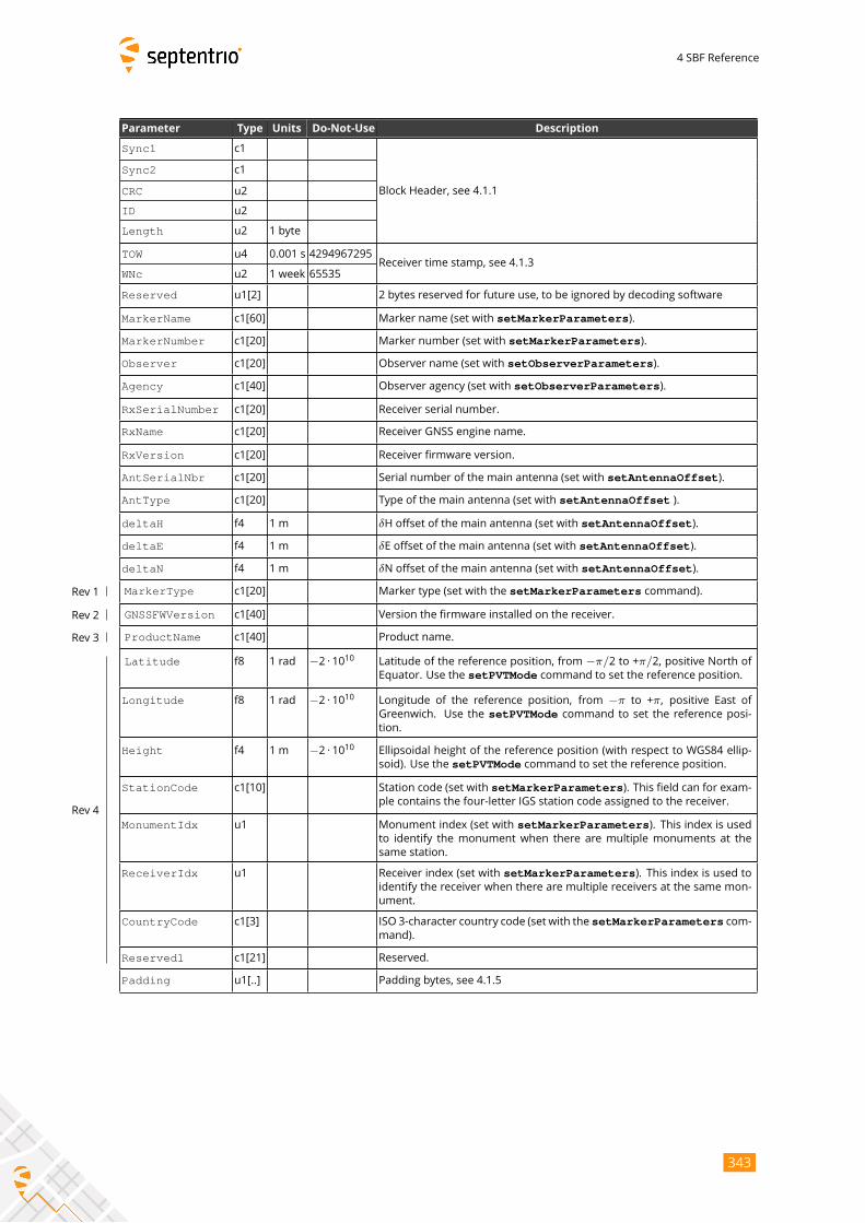
4 SBF Reference
Parameter Type Units Do-Not-Use Description
Sync1 c1
Block Header, see 4.1.1
Sync2 c1
CRC u2
ID u2
Length u2 1 byte
TOW u4 0.001 s 4294967295Receiver time stamp, see 4.1.3
WNc u2 1 week 65535
Reserved u1[2] 2 bytes reserved for future use, to be ignored by decoding software
MarkerName c1[60] Marker name (set with setMarkerParameters).
MarkerNumber c1[20] Marker number (set with setMarkerParameters).
Observer c1[20] Observer name (set with setObserverParameters).
Agency c1[40] Observer agency (set with setObserverParameters).
RxSerialNumber c1[20] Receiver serial number.
RxName c1[20] Receiver GNSS engine name.
RxVersion c1[20] Receiver firmware version.
AntSerialNbr c1[20] Serial number of the main antenna (set with setAntennaOffset).
AntType c1[20] Type of the main antenna (set with setAntennaOffset ).
deltaH f4 1 m δH offset of the main antenna (set with setAntennaOffset).
deltaE f4 1 m δE offset of the main antenna (set with setAntennaOffset).
deltaN f4 1 m δN offset of the main antenna (set with setAntennaOffset).
MarkerType c1[20] Marker type (set with the setMarkerParameters command).Rev 1
GNSSFWVersion c1[40] Version the firmware installed on the receiver.Rev 2
ProductName c1[40] Product name.Rev 3
Latitude f8 1 rad −2 · 1010 Latitude of the reference position, from −π/2 to +π/2, positive North ofEquator. Use the setPVTMode command to set the reference position.
Longitude f8 1 rad −2 · 1010 Longitude of the reference position, from −π to +π, positive East ofGreenwich. Use the setPVTMode command to set the reference posi-tion.
Height f4 1 m −2 · 1010 Ellipsoidal height of the reference position (with respect to WGS84 ellip-
soid). Use the setPVTMode command to set the reference position.
StationCode c1[10] Station code (set with setMarkerParameters). This field can for exam-ple contains the four-letter IGS station code assigned to the receiver.
MonumentIdx u1 Monument index (set with setMarkerParameters). This index is usedto identify the monument when there are multiple monuments at the
same station.
ReceiverIdx u1 Receiver index (set with setMarkerParameters). This index is used toidentify the receiver when there are multiple receivers at the same mon-
ument.
CountryCode c1[3] ISO 3-character country code (set with the setMarkerParameters com-mand).
Reserved1 c1[21] Reserved.
Rev 4
Padding u1[..] Padding bytes, see 4.1.5
343
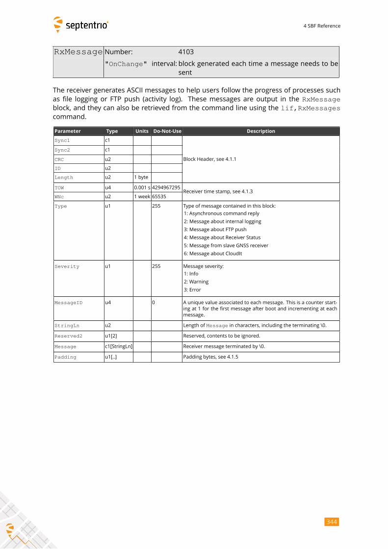
4 SBF Reference
RxMessage Number: 4103
"OnChange" interval: block generated each time a message needs to besent
The receiver generates ASCII messages to help users follow the progress of processes such
as file logging or FTP push (activity log). These messages are output in the RxMessageblock, and they can also be retrieved from the command line using the lif,RxMessagescommand.
Parameter Type Units Do-Not-Use Description
Sync1 c1
Block Header, see 4.1.1
Sync2 c1
CRC u2
ID u2
Length u2 1 byte
TOW u4 0.001 s 4294967295Receiver time stamp, see 4.1.3
WNc u2 1 week 65535
Type u1 255 Type of message contained in this block:
1: Asynchronous command reply
2: Message about internal logging
3: Message about FTP push
4: Message about Receiver Status
5: Message from slave GNSS receiver
6: Message about CloudIt
Severity u1 255 Message severity:
1: Info
2: Warning
3: Error
MessageID u4 0 A unique value associated to each message. This is a counter start-
ing at 1 for the first message after boot and incrementing at each
message.
StringLn u2 Length of Message in characters, including the terminating \0.
Reserved2 u1[2] Reserved, contents to be ignored.
Message c1[StringLn] Receiver message terminated by \0.
Padding u1[..] Padding bytes, see 4.1.5
344

4 SBF Reference
Commands Number: 4015
"OnChange" interval: each time a user command is entered
Every time the user sends a command, a Commands block is output on all ports for whichthis block is enabled. The Commands SBF block is inserted in the SBF stream at the verymoment when the command starts to take effect.
Parameter Type Units Do-Not-Use Description
Sync1 c1
Block Header, see 4.1.1
Sync2 c1
CRC u2
ID u2
Length u2 1 byte
TOW u4 0.001 s 4294967295Receiver time stamp, see 4.1.3
WNc u2 1 week 65535
Reserved u1[2] Reserved for future use, to be ignored by decoding software.
CmdData u1[N] Command data, this is the command in the SNMP’ format (reserved for
maintenance and support only).
Padding u1[..] Padding bytes, see 4.1.5
345
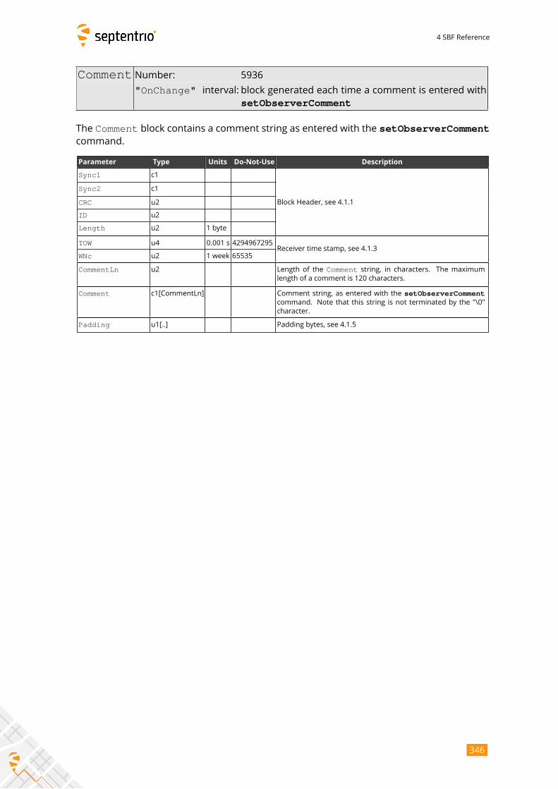
4 SBF Reference
Comment Number: 5936
"OnChange" interval: block generated each time a comment is entered withsetObserverComment
The Comment block contains a comment string as entered with the setObserverCommentcommand.
Parameter Type Units Do-Not-Use Description
Sync1 c1
Block Header, see 4.1.1
Sync2 c1
CRC u2
ID u2
Length u2 1 byte
TOW u4 0.001 s 4294967295Receiver time stamp, see 4.1.3
WNc u2 1 week 65535
CommentLn u2 Length of the Comment string, in characters. The maximumlength of a comment is 120 characters.
Comment c1[CommentLn] Comment string, as entered with the setObserverCommentcommand. Note that this string is not terminated by the "\0"
character.
Padding u1[..] Padding bytes, see 4.1.5
346
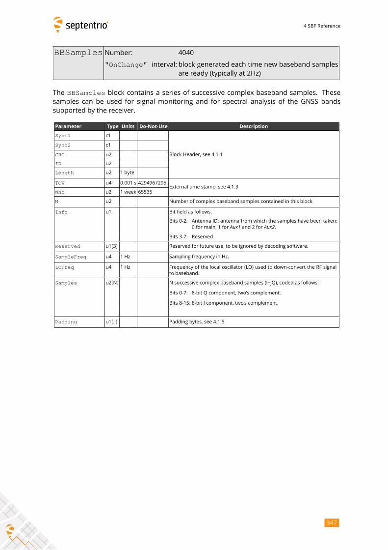
4 SBF Reference
BBSamples Number: 4040
"OnChange" interval: block generated each time new baseband samplesare ready (typically at 2Hz)
The BBSamples block contains a series of successive complex baseband samples. Thesesamples can be used for signal monitoring and for spectral analysis of the GNSS bands
supported by the receiver.
Parameter Type Units Do-Not-Use Description
Sync1 c1
Block Header, see 4.1.1
Sync2 c1
CRC u2
ID u2
Length u2 1 byte
TOW u4 0.001 s 4294967295External time stamp, see 4.1.3
WNc u2 1 week 65535
N u2 Number of complex baseband samples contained in this block
Info u1 Bit field as follows:
Bits 0-2: Antenna ID: antenna from which the samples have been taken:
0 for main, 1 for Aux1 and 2 for Aux2.Bits 3-7: Reserved
Reserved u1[3] Reserved for future use, to be ignored by decoding software.
SampleFreq u4 1 Hz Sampling frequency in Hz.
LOFreq u4 1 Hz Frequency of the local oscillator (LO) used to down-convert the RF signal
to baseband.
Samples u2[N] N successive complex baseband samples (I+jQ), coded as follows:
Bits 0-7: 8-bit Q component, two’s complement.
Bits 8-15: 8-bit I component, two’s complement.
Padding u1[..] Padding bytes, see 4.1.5
347
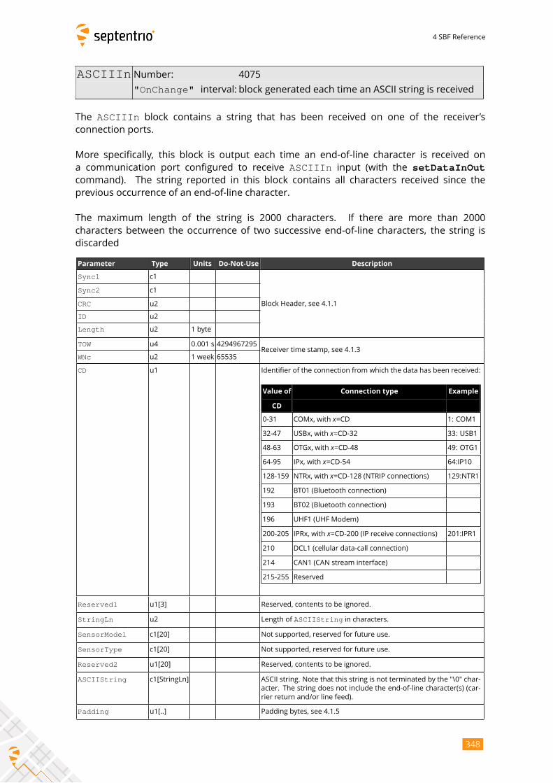
4 SBF Reference
ASCIIIn Number: 4075
"OnChange" interval: block generated each time an ASCII string is received
The ASCIIIn block contains a string that has been received on one of the receiver’sconnection ports.
More specifically, this block is output each time an end-of-line character is received on
a communication port configured to receive ASCIIIn input (with the setDataInOutcommand). The string reported in this block contains all characters received since the
previous occurrence of an end-of-line character.
The maximum length of the string is 2000 characters. If there are more than 2000
characters between the occurrence of two successive end-of-line characters, the string is
discarded
Parameter Type Units Do-Not-Use Description
Sync1 c1
Block Header, see 4.1.1
Sync2 c1
CRC u2
ID u2
Length u2 1 byte
TOW u4 0.001 s 4294967295Receiver time stamp, see 4.1.3
WNc u2 1 week 65535
CD u1 Identifier of the connection from which the data has been received:
Value of Connection type Example
CD
0-31 COMx, with x=CD 1: COM1
32-47 USBx, with x=CD-32 33: USB1
48-63 OTGx, with x=CD-48 49: OTG1
64-95 IPx, with x=CD-54 64:IP10
128-159 NTRx, with x=CD-128 (NTRIP connections) 129:NTR1
192 BT01 (Bluetooth connection)
193 BT02 (Bluetooth connection)
196 UHF1 (UHF Modem)
200-205 IPRx, with x=CD-200 (IP receive connections) 201:IPR1
210 DCL1 (cellular data-call connection)
214 CAN1 (CAN stream interface)
215-255 Reserved
Reserved1 u1[3] Reserved, contents to be ignored.
StringLn u2 Length of ASCIIString in characters.
SensorModel c1[20] Not supported, reserved for future use.
SensorType c1[20] Not supported, reserved for future use.
Reserved2 u1[20] Reserved, contents to be ignored.
ASCIIString c1[StringLn] ASCII string. Note that this string is not terminated by the "\0" char-
acter. The string does not include the end-of-line character(s) (car-
rier return and/or line feed).
Padding u1[..] Padding bytes, see 4.1.5
348
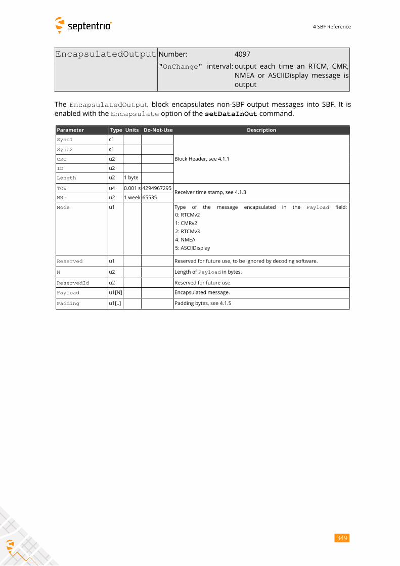
4 SBF Reference
EncapsulatedOutput Number: 4097
"OnChange" interval: output each time an RTCM, CMR,NMEA or ASCIIDisplay message is
output
The EncapsulatedOutput block encapsulates non-SBF output messages into SBF. It isenabled with the Encapsulate option of the setDataInOut command.
Parameter Type Units Do-Not-Use Description
Sync1 c1
Block Header, see 4.1.1
Sync2 c1
CRC u2
ID u2
Length u2 1 byte
TOW u4 0.001 s 4294967295Receiver time stamp, see 4.1.3
WNc u2 1 week 65535
Mode u1 Type of the message encapsulated in the Payload field:
0: RTCMv2
1: CMRv2
2: RTCMv3
4: NMEA
5: ASCIIDisplay
Reserved u1 Reserved for future use, to be ignored by decoding software.
N u2 Length of Payload in bytes.
ReservedId u2 Reserved for future use
Payload u1[N] Encapsulated message.
Padding u1[..] Padding bytes, see 4.1.5
349
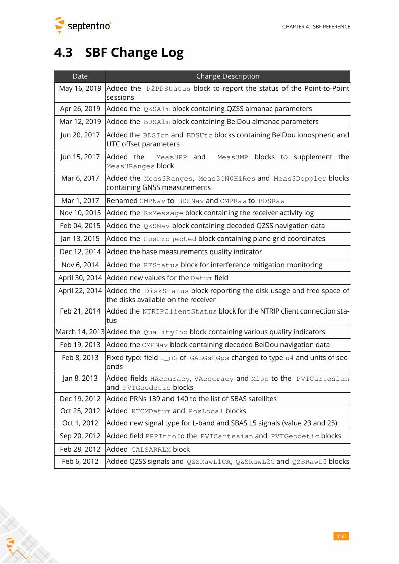
CHAPTER 4. SBF REFERENCE
4.3 SBF Change Log
Date Change Description
May 16, 2019 Added the P2PPStatus block to report the status of the Point-to-Pointsessions
Apr 26, 2019 Added the QZSAlm block containing QZSS almanac parameters
Mar 12, 2019 Added the BDSAlm block containing BeiDou almanac parameters
Jun 20, 2017 Added the BDSIon and BDSUtc blocks containing BeiDou ionospheric andUTC offset parameters
Jun 15, 2017 Added the Meas3PP and Meas3MP blocks to supplement the
Meas3Ranges block
Mar 6, 2017 Added the Meas3Ranges, Meas3CN0HiRes and Meas3Doppler blockscontaining GNSS measurements
Mar 1, 2017 Renamed CMPNav to BDSNav and CMPRaw to BDSRaw
Nov 10, 2015 Added the RxMessage block containing the receiver activity log
Feb 04, 2015 Added the QZSNav block containing decoded QZSS navigation data
Jan 13, 2015 Added the PosProjected block containing plane grid coordinates
Dec 12, 2014 Added the base measurements quality indicator
Nov 6, 2014 Added the RFStatus block for interference mitigation monitoring
April 30, 2014 Added new values for the Datum field
April 22, 2014 Added the DiskStatus block reporting the disk usage and free space ofthe disks available on the receiver
Feb 21, 2014 Added the NTRIPClientStatus block for the NTRIP client connection sta-tus
March 14, 2013 Added the QualityInd block containing various quality indicators
Feb 19, 2013 Added the CMPNav block containing decoded BeiDou navigation data
Feb 8, 2013 Fixed typo: field t_oG of GALGstGps changed to type u4 and units of sec-onds
Jan 8, 2013 Added fields HAccuracy, VAccuracy and Misc to the PVTCartesianand PVTGeodetic blocks
Dec 19, 2012 Added PRNs 139 and 140 to the list of SBAS satellites
Oct 25, 2012 Added RTCMDatum and PosLocal blocks
Oct 1, 2012 Added new signal type for L-band and SBAS L5 signals (value 23 and 25)
Sep 20, 2012 Added field PPPInfo to the PVTCartesian and PVTGeodetic blocks
Feb 28, 2012 Added GALSARRLM block
Feb 6, 2012 Added QZSS signals and QZSRawL1CA, QZSRawL2C and QZSRawL5 blocks
350

APPENDIX A. ATTITUDE ANGLES
Appendix A
Attitude Angles
The attitude of the vehicle is defined as the angles between the vehicle reference frame and
the local-level reference frame (defined by the East, North and Up directions). The vehicle
reference frame is defined as follows. It is attached to the vehicle and has its X axis pointing
along the longitudinal vehicle axis, the Y axis pointing towards the vehicle starboard (right)
side and the Z axis pointing down, as illustrated in Figure A-1.
X v
Y v Z v
Figure A-1: Vehicle reference frame.
Septentrio receivers express the vehicle attitude in Euler angles using the heading-pitch-roll
rotation sequence. More specifically, Euler angles are defined as successive rotations of the
vehicle frame (X, Y, Z axes) relative to the local-level East-North-Up reference frame. The
rotation sequence is shown in Figure A-2. The heading (ψ) of the vehicle is defined as theright-handed rotation of the vehicle about the Z axis (0
o ≤ ψ ≤ 360o). The pitch (θ) of thevehicle is defined as the right-handed rotation about the vehicle Y axis (−90o ≤ θ ≤ 90
o).
The roll (ϕ) of the vehicle is defined as the right-handed rotation about the vehicle X axis(−180o ≤ ϕ ≤ 180o).Starting from the situation where X points to the North, Y to the East and Z down, the fol-
lowing successive rotations define the attitude of the vehicle. Note that the order of the
rotations is important.
351
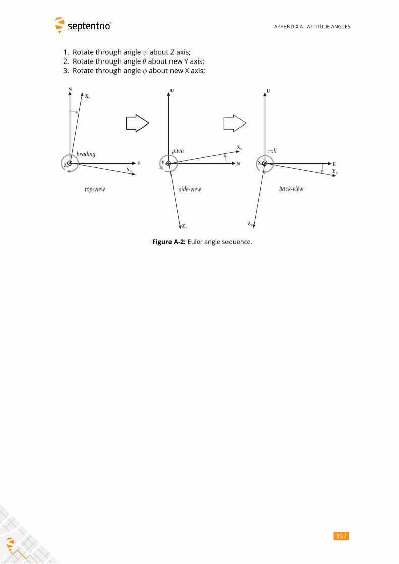
APPENDIX A. ATTITUDE ANGLES
1. Rotate through angle ψ about Z axis;2. Rotate through angle θ about new Y axis;3. Rotate through angle ϕ about new X axis;
top-view side-view back-view
U
E X v
Y v
Z v
roll
U
N Y v
X v
Z v
pitch heading
N
Y v
X v
Z v E
Figure A-2: Euler angle sequence.
352
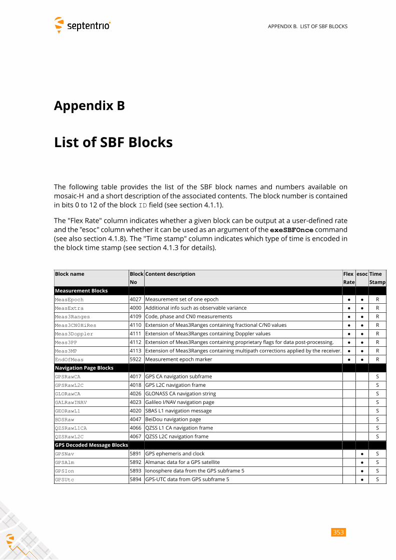
APPENDIX B. LIST OF SBF BLOCKS
Appendix B
List of SBF Blocks
The following table provides the list of the SBF block names and numbers available on
mosaic-H and a short description of the associated contents. The block number is contained
in bits 0 to 12 of the block ID field (see section 4.1.1).
The "Flex Rate" column indicates whether a given block can be output at a user-defined rate
and the "esoc" columnwhether it can be used as an argument of the exeSBFOnce command(see also section 4.1.8). The "Time stamp" column indicates which type of time is encoded in
the block time stamp (see section 4.1.3 for details).
Block name Block Content description Flex esoc Time
No Rate Stamp
Measurement Blocks
MeasEpoch 4027 Measurement set of one epoch • • R
MeasExtra 4000 Additional info such as observable variance • • R
Meas3Ranges 4109 Code, phase and CN0 measurements • • R
Meas3CN0HiRes 4110 Extension of Meas3Ranges containing fractional C/N0 values • • R
Meas3Doppler 4111 Extension of Meas3Ranges containing Doppler values • • R
Meas3PP 4112 Extension of Meas3Ranges containing proprietary flags for data post-processing. • • R
Meas3MP 4113 Extension of Meas3Ranges containing multipath corrections applied by the receiver. • • R
EndOfMeas 5922 Measurement epoch marker • • R
Navigation Page Blocks
GPSRawCA 4017 GPS CA navigation subframe S
GPSRawL2C 4018 GPS L2C navigation frame S
GLORawCA 4026 GLONASS CA navigation string S
GALRawINAV 4023 Galileo I/NAV navigation page S
GEORawL1 4020 SBAS L1 navigation message S
BDSRaw 4047 BeiDou navigation page S
QZSRawL1CA 4066 QZSS L1 CA navigation frame S
QZSRawL2C 4067 QZSS L2C navigation frame S
GPS Decoded Message Blocks
GPSNav 5891 GPS ephemeris and clock • S
GPSAlm 5892 Almanac data for a GPS satellite • S
GPSIon 5893 Ionosphere data from the GPS subframe 5 • S
GPSUtc 5894 GPS-UTC data from GPS subframe 5 • S
353
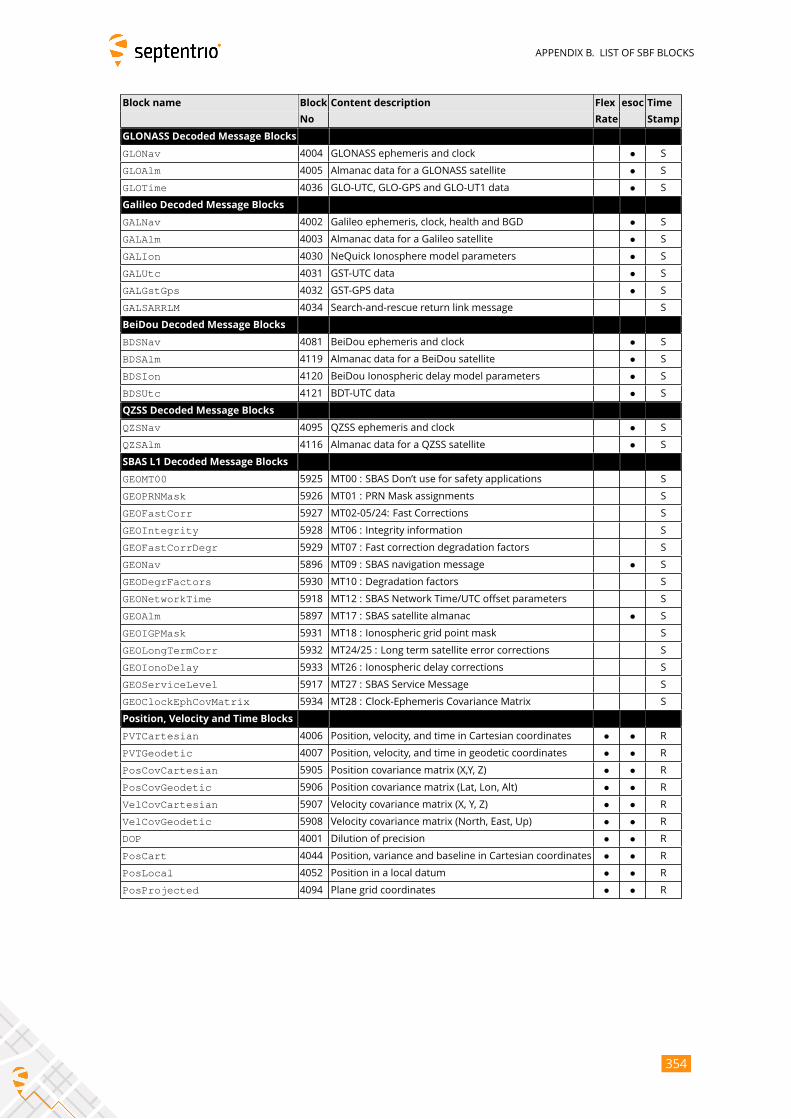
APPENDIX B. LIST OF SBF BLOCKS
Block name Block Content description Flex esoc Time
No Rate Stamp
GLONASS Decoded Message Blocks
GLONav 4004 GLONASS ephemeris and clock • S
GLOAlm 4005 Almanac data for a GLONASS satellite • S
GLOTime 4036 GLO-UTC, GLO-GPS and GLO-UT1 data • S
Galileo Decoded Message Blocks
GALNav 4002 Galileo ephemeris, clock, health and BGD • S
GALAlm 4003 Almanac data for a Galileo satellite • S
GALIon 4030 NeQuick Ionosphere model parameters • S
GALUtc 4031 GST-UTC data • S
GALGstGps 4032 GST-GPS data • S
GALSARRLM 4034 Search-and-rescue return link message S
BeiDou Decoded Message Blocks
BDSNav 4081 BeiDou ephemeris and clock • S
BDSAlm 4119 Almanac data for a BeiDou satellite • S
BDSIon 4120 BeiDou Ionospheric delay model parameters • S
BDSUtc 4121 BDT-UTC data • S
QZSS Decoded Message Blocks
QZSNav 4095 QZSS ephemeris and clock • S
QZSAlm 4116 Almanac data for a QZSS satellite • S
SBAS L1 Decoded Message Blocks
GEOMT00 5925 MT00 : SBAS Don’t use for safety applications S
GEOPRNMask 5926 MT01 : PRN Mask assignments S
GEOFastCorr 5927 MT02-05/24: Fast Corrections S
GEOIntegrity 5928 MT06 : Integrity information S
GEOFastCorrDegr 5929 MT07 : Fast correction degradation factors S
GEONav 5896 MT09 : SBAS navigation message • S
GEODegrFactors 5930 MT10 : Degradation factors S
GEONetworkTime 5918 MT12 : SBAS Network Time/UTC offset parameters S
GEOAlm 5897 MT17 : SBAS satellite almanac • S
GEOIGPMask 5931 MT18 : Ionospheric grid point mask S
GEOLongTermCorr 5932 MT24/25 : Long term satellite error corrections S
GEOIonoDelay 5933 MT26 : Ionospheric delay corrections S
GEOServiceLevel 5917 MT27 : SBAS Service Message S
GEOClockEphCovMatrix 5934 MT28 : Clock-Ephemeris Covariance Matrix S
Position, Velocity and Time Blocks
PVTCartesian 4006 Position, velocity, and time in Cartesian coordinates • • R
PVTGeodetic 4007 Position, velocity, and time in geodetic coordinates • • R
PosCovCartesian 5905 Position covariance matrix (X,Y, Z) • • R
PosCovGeodetic 5906 Position covariance matrix (Lat, Lon, Alt) • • R
VelCovCartesian 5907 Velocity covariance matrix (X, Y, Z) • • R
VelCovGeodetic 5908 Velocity covariance matrix (North, East, Up) • • R
DOP 4001 Dilution of precision • • R
PosCart 4044 Position, variance and baseline in Cartesian coordinates • • R
PosLocal 4052 Position in a local datum • • R
PosProjected 4094 Plane grid coordinates • • R
354
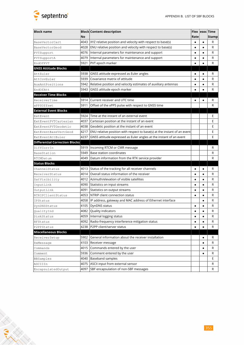
APPENDIX B. LIST OF SBF BLOCKS
Block name Block Content description Flex esoc Time
No Rate Stamp
BaseVectorCart 4043 XYZ relative position and velocity with respect to base(s) • • R
BaseVectorGeod 4028 ENU relative position and velocity with respect to base(s) • • R
PVTSupport 4076 Internal parameters for maintenance and support • • R
PVTSupportA 4079 Internal parameters for maintenance and support • • R
EndOfPVT 5921 PVT epoch marker • • R
GNSS Attitude Blocks
AttEuler 5938 GNSS attitude expressed as Euler angles • • R
AttCovEuler 5939 Covariance matrix of attitude • • R
AuxAntPositions 5942 Relative position and velocity estimates of auxiliary antennas • • R
EndOfAtt 5943 GNSS attitude epoch marker • • R
Receiver Time Blocks
ReceiverTime 5914 Current receiver and UTC time • • R
xPPSOffset 5911 Offset of the xPPS pulse with respect to GNSS time R
External Event Blocks
ExtEvent 5924 Time at the instant of an external event E
ExtEventPVTCartesian 4037 Cartesian position at the instant of an event E
ExtEventPVTGeodetic 4038 Geodetic position at the instant of an event E
ExtEventBaseVectGeod 4217 ENU relative position with respect to base(s) at the instant of an event E
ExtEventAttEuler 4237 GNSS attitude expressed as Euler angles at the instant of an event E
Differential Correction Blocks
DiffCorrIn 5919 Incoming RTCM or CMR message R
BaseStation 5949 Base station coordinates R
RTCMDatum 4049 Datum information from the RTK service provider R
Status Blocks
ChannelStatus 4013 Status of the tracking for all receiver channels • • R
ReceiverStatus 4014 Overall status information of the receiver • • R
SatVisibility 4012 Azimuth/elevation of visible satellites • • R
InputLink 4090 Statistics on input streams • • R
OutputLink 4091 Statistics on output streams • • R
NTRIPClientStatus 4053 NTRIP client connection status • • R
IPStatus 4058 IP address, gateway and MAC address of Ethernet interface • R
DynDNSStatus 4105 DynDNS status • • R
QualityInd 4082 Quality indicators • • R
DiskStatus 4059 Internal logging status • • R
RFStatus 4092 Radio-frequency interference mitigation status • • R
P2PPStatus 4238 P2PP client/server status • • R
Miscellaneous Blocks
ReceiverSetup 5902 General information about the receiver installation • R
RxMessage 4103 Receiver message • R
Commands 4015 Commands entered by the user • R
Comment 5936 Comment entered by the user • R
BBSamples 4040 Baseband samples E
ASCIIIn 4075 ASCII input from external sensor R
EncapsulatedOutput 4097 SBF encapsulation of non-SBF messages R
355

APPENDIX C. LIST OF NMEA SENTENCES
Appendix C
List of NMEA Sentences
The following table provides a list of the NMEA messages supported by your receiver.
The first column is the message identifier to be used in the setNMEAOutput and theexeNMEAOnce commands.
For a full description of the NMEA messages, please refer to the NMEA 0183 standard.
Message
Identifier
NMEA For-
matter
Short Description Comment
ALM ALM GPS Almanac Data
AVR AVR Trimble Navigation proprietary
$PTNL,AVR sentence
DTM DTM Datum Reference
GBS GBS GNSS Satellite Fault Detection
GFA GFA GNSS Fix Accuracy and Integrity
GGA GGA GPS Fix Data
GGAaux1 GGA GPS Fix Data GGA sentence containing the position of the aux1
antenna
GGK GGK Trimble Navigation proprietary
$PTNL,GGK sentence
GGQ GGQ Leica Real-Time Position with CQ
GLL GLL Geographic Position - Latitude/Longi-
tude
GMP GMP GNSS Map Projection Fix Data
GNS GNS GNSS Fix Data
GRS GRS GNSS Range Residuals
GSA GSA GNSS DOP and Active Satellites
GST GST GNSS Pseudorange Error Statistics
GSV GSV GNSS Satellites in View
HDT HDT Heading, True
HRP HRP Heading, Roll, Pitch Septentrio proprietary, see section C.1.1
LLK LLK Leica Local Position and GDOP
LLQ LLQ Leica Local Position and Quality
RBD RBD Rover-Base Direction Septentrio proprietary, see section C.1.2
RBP RBP Rover-Base Position Septentrio proprietary, see section C.1.3
RBV RBV Rover-Base Velocity Septentrio proprietary, see section C.1.4
356
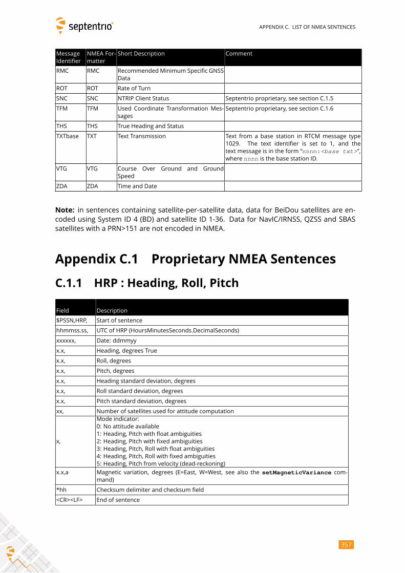
APPENDIX C. LIST OF NMEA SENTENCES
Message
Identifier
NMEA For-
matter
Short Description Comment
RMC RMC RecommendedMinimum Specific GNSS
Data
ROT ROT Rate of Turn
SNC SNC NTRIP Client Status Septentrio proprietary, see section C.1.5
TFM TFM Used Coordinate Transformation Mes-
sages
Septentrio proprietary, see section C.1.6
THS THS True Heading and Status
TXTbase TXT Text Transmission Text from a base station in RTCM message type
1029. The text identifier is set to 1, and the
text message is in the form “nnnn:<base txt>”,where nnnn is the base station ID.
VTG VTG Course Over Ground and Ground
Speed
ZDA ZDA Time and Date
Note: in sentences containing satellite-per-satellite data, data for BeiDou satellites are en-
coded using System ID 4 (BD) and satellite ID 1-36. Data for NavIC/IRNSS, QZSS and SBAS
satellites with a PRN>151 are not encoded in NMEA.
Appendix C.1 Proprietary NMEA Sentences
C.1.1 HRP : Heading, Roll, Pitch
Field Description
$PSSN,HRP, Start of sentence
hhmmss.ss, UTC of HRP (HoursMinutesSeconds.DecimalSeconds)
xxxxxx, Date: ddmmyy
x.x, Heading, degrees True
x.x, Roll, degrees
x.x, Pitch, degrees
x.x, Heading standard deviation, degrees
x.x, Roll standard deviation, degrees
x.x, Pitch standard deviation, degrees
xx, Number of satellites used for attitude computation
x,
Mode indicator:
0: No attitude available
1: Heading, Pitch with float ambiguities
2: Heading, Pitch with fixed ambiguities
3: Heading, Pitch, Roll with float ambiguities
4: Heading, Pitch, Roll with fixed ambiguities
5: Heading, Pitch from velocity (dead-reckoning)
x.x,a Magnetic variation, degrees (E=East, W=West, see also the setMagneticVariance com-mand)
*hh Checksum delimiter and checksum field
<CR><LF> End of sentence
357
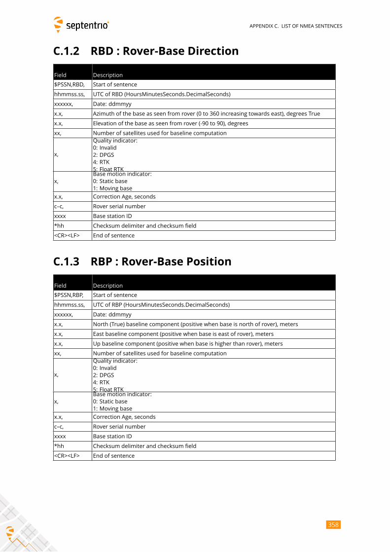
APPENDIX C. LIST OF NMEA SENTENCES
C.1.2 RBD : Rover-Base Direction
Field Description
$PSSN,RBD, Start of sentence
hhmmss.ss, UTC of RBD (HoursMinutesSeconds.DecimalSeconds)
xxxxxx, Date: ddmmyy
x.x, Azimuth of the base as seen from rover (0 to 360 increasing towards east), degrees True
x.x, Elevation of the base as seen from rover (-90 to 90), degrees
xx, Number of satellites used for baseline computation
x,
Quality indicator:
0: Invalid
2: DPGS
4: RTK
5: Float RTK
x,
Base motion indicator:
0: Static base
1: Moving base
x.x, Correction Age, seconds
c–c, Rover serial number
xxxx Base station ID
*hh Checksum delimiter and checksum field
<CR><LF> End of sentence
C.1.3 RBP : Rover-Base Position
Field Description
$PSSN,RBP, Start of sentence
hhmmss.ss, UTC of RBP (HoursMinutesSeconds.DecimalSeconds)
xxxxxx, Date: ddmmyy
x.x, North (True) baseline component (positive when base is north of rover), meters
x.x, East baseline component (positive when base is east of rover), meters
x.x, Up baseline component (positive when base is higher than rover), meters
xx, Number of satellites used for baseline computation
x,
Quality indicator:
0: Invalid
2: DPGS
4: RTK
5: Float RTK
x,
Base motion indicator:
0: Static base
1: Moving base
x.x, Correction Age, seconds
c–c, Rover serial number
xxxx Base station ID
*hh Checksum delimiter and checksum field
<CR><LF> End of sentence
358
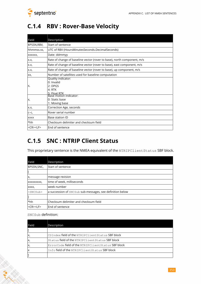
APPENDIX C. LIST OF NMEA SENTENCES
C.1.4 RBV : Rover-Base Velocity
Field Description
$PSSN,RBV, Start of sentence
hhmmss.ss, UTC of RBV (HoursMinutesSeconds.DecimalSeconds)
xxxxxx, Date: ddmmyy
x.x, Rate of change of baseline vector (rover to base), north component, m/s
x.x, Rate of change of baseline vector (rover to base), east component, m/s
x.x, Rate of change of baseline vector (rover to base), up component, m/s
xx, Number of satellites used for baseline computation
x,
Quality indicator:
0: Invalid
2: DPGS
4: RTK
5: Float RTK
x,
Base motion indicator:
0: Static base
1: Moving base
x.x, Correction Age, seconds
c–c, Rover serial number
xxxx Base station ID
*hh Checksum delimiter and checksum field
<CR><LF> End of sentence
C.1.5 SNC : NTRIP Client Status
This proprietary sentence is the NMEA equivalent of the NTRIPClientStatus SBF block.
Field Description
$PSSN,SNC, Start of sentence
[
x, message revision
xxxxxxxxx, time of week, milliseconds
xxxx, week number
<SNCSub> a succession of SNCSub sub-messages, see definition below
]
*hh Checksum delimiter and checksum field
<CR><LF> End of sentence
SNCSub definition:
Field Description
[
x, CDIndex field of the NTRIPClientStatus SBF block
x, Status field of the NTRIPClientStatus SBF block
x, ErrorCode field of the NTRIPClientStatus SBF block
x Info field of the NTRIPClientStatus SBF block
]
359
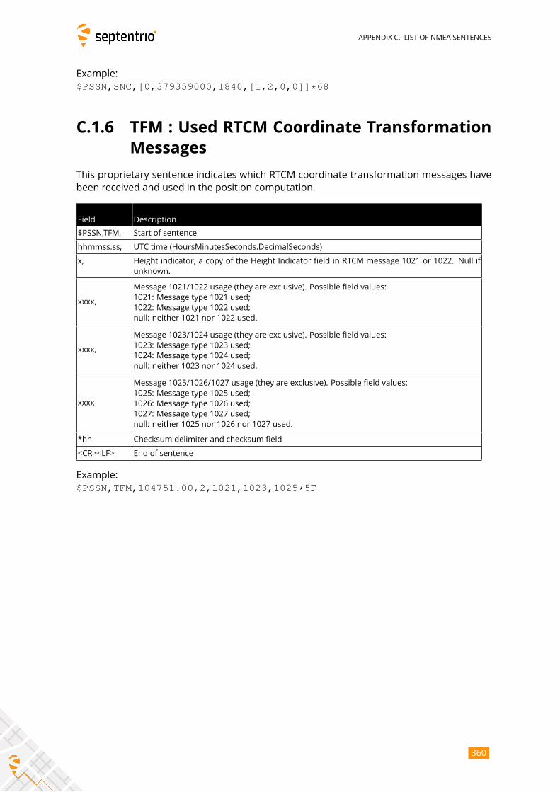
APPENDIX C. LIST OF NMEA SENTENCES
Example:
$PSSN,SNC,[0,379359000,1840,[1,2,0,0]]*68
C.1.6 TFM : Used RTCM Coordinate Transformation
Messages
This proprietary sentence indicates which RTCM coordinate transformation messages have
been received and used in the position computation.
Field Description
$PSSN,TFM, Start of sentence
hhmmss.ss, UTC time (HoursMinutesSeconds.DecimalSeconds)
x, Height indicator, a copy of the Height Indicator field in RTCM message 1021 or 1022. Null if
unknown.
xxxx,
Message 1021/1022 usage (they are exclusive). Possible field values:
1021: Message type 1021 used;
1022: Message type 1022 used;
null: neither 1021 nor 1022 used.
xxxx,
Message 1023/1024 usage (they are exclusive). Possible field values:
1023: Message type 1023 used;
1024: Message type 1024 used;
null: neither 1023 nor 1024 used.
xxxx
Message 1025/1026/1027 usage (they are exclusive). Possible field values:
1025: Message type 1025 used;
1026: Message type 1026 used;
1027: Message type 1027 used;
null: neither 1025 nor 1026 nor 1027 used.
*hh Checksum delimiter and checksum field
<CR><LF> End of sentence
Example:
$PSSN,TFM,104751.00,2,1021,1023,1025*5F
360
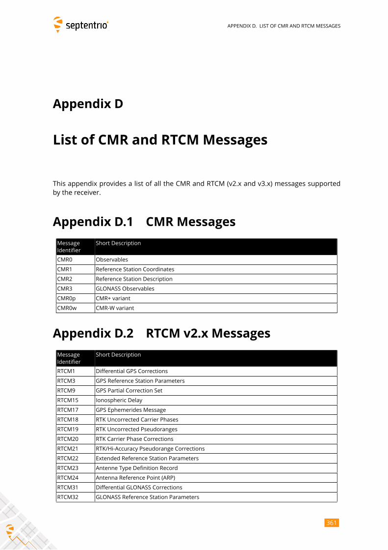
APPENDIX D. LIST OF CMR AND RTCM MESSAGES
Appendix D
List of CMR and RTCM Messages
This appendix provides a list of all the CMR and RTCM (v2.x and v3.x) messages supported
by the receiver.
Appendix D.1 CMR Messages
Message
Identifier
Short Description
CMR0 Observables
CMR1 Reference Station Coordinates
CMR2 Reference Station Description
CMR3 GLONASS Observables
CMR0p CMR+ variant
CMR0w CMR-W variant
Appendix D.2 RTCM v2.x Messages
Message
Identifier
Short Description
RTCM1 Differential GPS Corrections
RTCM3 GPS Reference Station Parameters
RTCM9 GPS Partial Correction Set
RTCM15 Ionospheric Delay
RTCM17 GPS Ephemerides Message
RTCM18 RTK Uncorrected Carrier Phases
RTCM19 RTK Uncorrected Pseudoranges
RTCM20 RTK Carrier Phase Corrections
RTCM21 RTK/Hi-Accuracy Pseudorange Corrections
RTCM22 Extended Reference Station Parameters
RTCM23 Antenne Type Definition Record
RTCM24 Antenna Reference Point (ARP)
RTCM31 Differential GLONASS Corrections
RTCM32 GLONASS Reference Station Parameters
361
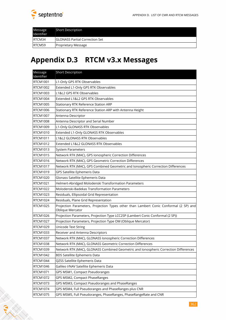
APPENDIX D. LIST OF CMR AND RTCM MESSAGES
Message
Identifier
Short Description
RTCM34 GLONASS Partial Correction Set
RTCM59 Proprietary Message
Appendix D.3 RTCM v3.x Messages
Message
Identifier
Short Description
RTCM1001 L1-Only GPS RTK Observables
RTCM1002 Extended L1-Only GPS RTK Observables
RTCM1003 L1&L2 GPS RTK Observables
RTCM1004 Extended L1&L2 GPS RTK Observables
RTCM1005 Stationary RTK Reference Station ARP
RTCM1006 Stationary RTK Reference Station ARP with Antenna Height
RTCM1007 Antenna Descriptor
RTCM1008 Antenna Descriptor and Serial Number
RTCM1009 L1-Only GLONASS RTK Observables
RTCM1010 Extended L1-Only GLONASS RTK Observables
RTCM1011 L1&L2 GLONASS RTK Observables
RTCM1012 Extended L1&L2 GLONASS RTK Observables
RTCM1013 System Parameters
RTCM1015 Network RTK (MAC), GPS Ionospheric Correction Differences
RTCM1016 Network RTK (MAC), GPS Geometric Correction Differences
RTCM1017 Network RTK (MAC), GPS Combined Geometric and Ionospheric Correction Differences
RTCM1019 GPS Satellite Ephemeris Data
RTCM1020 Glonass Satellite Ephemeris Data
RTCM1021 Helmert-Abridged Molodenski Transformation Parameters
RTCM1022 Molodenski-Badekas Transformation Parameters
RTCM1023 Residuals, Ellipsoidal Grid Representation
RTCM1024 Residuals, Plane Grid Representation
RTCM1025 Projection Parameters, Projection Types other than Lambert Conic Conformal (2 SP) and
Oblique Mercator
RTCM1026 Projection Parameters, Projection Type LCC2SP (Lambert Conic Conformal (2 SP))
RTCM1027 Projection Parameters, Projection Type OM (Oblique Mercator)
RTCM1029 Unicode Text String
RTCM1033 Receiver and Antenna Descriptors
RTCM1037 Network RTK (MAC), GLONASS Ionospheric Correction Differences
RTCM1038 Network RTK (MAC), GLONASS Geometric Correction Differences
RTCM1039 Network RTK (MAC), GLONASS Combined Geometric and Ionospheric Correction Differences
RTCM1042 BDS Satellite Ephemeris Data
RTCM1044 QZSS Satellite Ephemeris Data
RTCM1046 Galileo I/NAV Satellite Ephemeris Data
RTCM1071 GPS MSM1, Compact Pseudoranges
RTCM1072 GPS MSM2, Compact PhaseRanges
RTCM1073 GPS MSM3, Compact Pseudoranges and PhaseRanges
RTCM1074 GPS MSM4, Full Pseudoranges and PhaseRanges plus CNR
RTCM1075 GPS MSM5, Full Pseudoranges, PhaseRanges, PhaseRangeRate and CNR
362
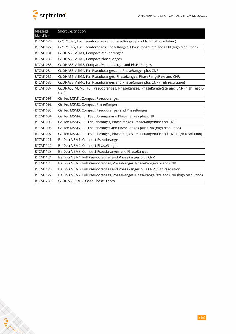
APPENDIX D. LIST OF CMR AND RTCM MESSAGES
Message
Identifier
Short Description
RTCM1076 GPS MSM6, Full Pseudoranges and PhaseRanges plus CNR (high resolution)
RTCM1077 GPS MSM7, Full Pseudoranges, PhaseRanges, PhaseRangeRate and CNR (high resolution)
RTCM1081 GLONASS MSM1, Compact Pseudoranges
RTCM1082 GLONASS MSM2, Compact PhaseRanges
RTCM1083 GLONASS MSM3, Compact Pseudoranges and PhaseRanges
RTCM1084 GLONASS MSM4, Full Pseudoranges and PhaseRanges plus CNR
RTCM1085 GLONASS MSM5, Full Pseudoranges, PhaseRanges, PhaseRangeRate and CNR
RTCM1086 GLONASS MSM6, Full Pseudoranges and PhaseRanges plus CNR (high resolution)
RTCM1087 GLONASS MSM7, Full Pseudoranges, PhaseRanges, PhaseRangeRate and CNR (high resolu-
tion)
RTCM1091 Galileo MSM1, Compact Pseudoranges
RTCM1092 Galileo MSM2, Compact PhaseRanges
RTCM1093 Galileo MSM3, Compact Pseudoranges and PhaseRanges
RTCM1094 Galileo MSM4, Full Pseudoranges and PhaseRanges plus CNR
RTCM1095 Galileo MSM5, Full Pseudoranges, PhaseRanges, PhaseRangeRate and CNR
RTCM1096 Galileo MSM6, Full Pseudoranges and PhaseRanges plus CNR (high resolution)
RTCM1097 Galileo MSM7, Full Pseudoranges, PhaseRanges, PhaseRangeRate and CNR (high resolution)
RTCM1121 BeiDou MSM1, Compact Pseudoranges
RTCM1122 BeiDou MSM2, Compact PhaseRanges
RTCM1123 BeiDou MSM3, Compact Pseudoranges and PhaseRanges
RTCM1124 BeiDou MSM4, Full Pseudoranges and PhaseRanges plus CNR
RTCM1125 BeiDou MSM5, Full Pseudoranges, PhaseRanges, PhaseRangeRate and CNR
RTCM1126 BeiDou MSM6, Full Pseudoranges and PhaseRanges plus CNR (high resolution)
RTCM1127 BeiDou MSM7, Full Pseudoranges, PhaseRanges, PhaseRangeRate and CNR (high resolution)
RTCM1230 GLONASS L1&L2 Code-Phase Biases
363
INDEX OF COMMANDS
Index of Commands
AAGCMode
setAGCMode, getAGCMode
sam, gam, 85
AntennaInfo
lstAntennaInfo
lai, 54
AntennaLocation
setAntennaLocation, getAntennaLocation
sal, gal, 111
AntennaOffset
setAntennaOffset, getAntennaOffset
sao, gao, 90
AttitudeOffset
setAttitudeOffset, getAttitudeOffset
sto, gto, 112
BBBSamplingMode
setBBSamplingMode, getBBSamplingMode
sbbs, gbbs, 86
CChannelAllocation
setChannelAllocation, getChannelAllocation
sca, gca, 77
CheckInternetAvailability
setCheckInternetAvailability, getCheckInternetAvailability
scia, gcia, 131
ClockSyncThreshold
setClockSyncThreshold, getClockSyncThreshold
scst, gcst, 123
CMRv2Usage
setCMRv2Usage, getCMRv2Usage
sc2u, gc2u, 170
CN0Mask
setCN0Mask, getCN0Mask
scm, gcm, 78
CommandHelp
lstCommandHelp
help, 55
364
INDEX OF COMMANDS
COMSettings
setCOMSettings, getCOMSettings
scs, gcs, 132
ConfigFile
lstConfigFile
lcf, 56
CopyConfigFile
exeCopyConfigFile, getCopyConfigFile
eccf, gccf, 57
CrossDomainWebAccess
setCrossDomainWebAccess, getCrossDomainWebAccess
scda, gcda, 133
CurrentUser
lstCurrentUser
lcu, 72
DDaisyChainMode
setDaisyChainMode, getDaisyChainMode
sdcm, gdcm, 134
DataInOut
setDataInOut, getDataInOut
sdio, gdio, 135
DefaultAccessLevel
setDefaultAccessLevel, getDefaultAccessLevel
sdal, gdal, 73
DiffCorrMaxAge
setDiffCorrMaxAge, getDiffCorrMaxAge
sdca, gdca, 91
DiffCorrUsage
setDiffCorrUsage, getDiffCorrUsage
sdcu, gdcu, 92
DiskFullAction
setDiskFullAction, getDiskFullAction
sdfa, gdfa, 171
DiskInfo
lstDiskInfo
ldi, 172
DynamicDNS
setDynamicDNS, getDynamicDNS
sdds, gdds, 137
EEchoMessage
exeEchoMessage, getEchoMessage
eecm, gecm, 138
ElevationMask
setElevationMask, getElevationMask
sem, gem, 93
ENHTransfoHorizontal
setENHTransfoHorizontal, getENHTransfoHorizontal
smth, gmth, 119
365
INDEX OF COMMANDS
ENHTransfoVertical
setENHTransfoVertical, getENHTransfoVertical
smtv, gmtv, 120
EthernetMode
setEthernetMode, getEthernetMode
seth, geth, 58
EventParameters
setEventParameters, getEventParameters
sep, gep, 124
FFileNaming
setFileNaming, getFileNaming
sfn, gfn, 173
FrontendMode
setFrontendMode, getFrontendMode
sfm, gfm, 87
FTPPushRINEX
setFTPPushRINEX, getFTPPushRINEX
sfpr, gfpr, 182
FTPPushSBF
setFTPPushSBF, getFTPPushSBF
sfps, gfps, 183
FTPPushTest
exeFTPPushTest, getFTPPushTest
efpt, gfpt, 184
FTPUpgrade
exeFTPUpgrade, getFTPUpgrade
efup, gfup, 59
GGeodeticDatum
setGeodeticDatum, getGeodeticDatum
sgd, ggd, 114
GeoidUndulation
setGeoidUndulation, getGeoidUndulation
sgu, ggu, 94
GlobalFileNamingOptions
setGlobalFileNamingOptions, getGlobalFileNamingOptions
sfno, gfno, 175
GNSSAttitude
setGNSSAttitude, getGNSSAttitude
sga, gga, 113
GPIOFunctionality
setGPIOFunctionality, getGPIOFunctionality
sgpf, ggpf, 60
HHealthMask
setHealthMask, getHealthMask
shm, ghm, 95
HttpsSettings
setHttpsSettings, getHttpsSettings
366
INDEX OF COMMANDS
shs, ghs, 140
IInternalFile
lstInternalFile
lif, 61
IonosphereModel
setIonosphereModel, getIonosphereModel
sim, gim, 96
IPFiltering
setIPFiltering, getIPFiltering
sipf, gipf, 141
IPPortSettings
setIPPortSettings, getIPPortSettings
sipp, gipp, 142
IPReceiveSettings
setIPReceiveSettings, getIPReceiveSettings
sirs, girs, 143
IPServerSettings
setIPServerSettings, getIPServerSettings
siss, giss, 144
IPSettings
setIPSettings, getIPSettings
sips, gips, 145
LLEDMode
setLEDMode, getLEDMode
slm, glm, 62
LocalCoordOperation
setLocalCoordOperation, getLocalCoordOperation
slco, glco, 121
LocalCoordOperations
lstLocalCoordOperations
llc, 122
LogIn
LogIn
login, 74
LogOut
LogOut
logout, 75
MMagneticVariance
setMagneticVariance, getMagneticVariance
smv, gmv, 98
ManageDisk
exeManageDisk, getManageDisk
emd, gmd, 176
MarkerParameters
setMarkerParameters, getMarkerParameters
smp, gmp, 128
Meas3MaxRefInterval
367
INDEX OF COMMANDS
setMeas3MaxRefInterval, getMeas3MaxRefInterval
smrf, gmrf, 159
MIBDescription
lstMIBDescription
lmd, 63
MultipathMitigation
setMultipathMitigation, getMultipathMitigation
smm, gmm, 79
NNetworkRTKConfig
setNetworkRTKConfig, getNetworkRTKConfig
snrc, gnrc, 99
NMEAOnce
exeNMEAOnce, getNMEAOnce
enoc, gnoc, 153
NMEAOutput
setNMEAOutput, getNMEAOutput
sno, gno, 154
NMEAPrecision
setNMEAPrecision, getNMEAPrecision
snp, gnp, 156
NMEATalkerID
setNMEATalkerID, getNMEATalkerID
snti, gnti, 157
NMEAVersion
setNMEAVersion, getNMEAVersion
snv, gnv, 158
NotchFiltering
setNotchFiltering, getNotchFiltering
snf, gnf, 88
NTPServer
setNTPServer, getNTPServer
sntp, gntp, 125
NtripSettings
setNtripSettings, getNtripSettings
snts, gnts, 150
NTRIPSourceTable
lstNTRIPSourceTable
lnst, 151
NtripTlsSettings
setNtripTlsSettings, getNtripTlsSettings
sntt, gntt, 152
OObserverComment
setObserverComment, getObserverComment
soc, goc, 129
ObserverParameters
setObserverParameters, getObserverParameters
sop, gop, 130
368
INDEX OF COMMANDS
PPeriodicEcho
setPeriodicEcho, getPeriodicEcho
spe, gpe, 146
PointToPoint
setPointToPoint, getPointToPoint
sp2p, gp2p, 148
PortFirewall
setPortFirewall, getPortFirewall
spfw, gpfw, 149
PowerMode
exePowerMode, getPowerMode
epwm, gpwm, 71
PPSParameters
setPPSParameters, getPPSParameters
spps, gpps, 126
PVTMode
setPVTMode, getPVTMode
spm, gpm, 100
RRAIMLevels
setRAIMLevels, getRAIMLevels
srl, grl, 101
ReceiverCapabilities
getReceiverCapabilities
grc, 64
ReceiverDynamics
setReceiverDynamics, getReceiverDynamics
srd, grd, 102
ReceiverInterface
getReceiverInterface
gri, 67
RecordedFile
lstRecordedFile
lrf, 177
RegisteredApplications
exeRegisteredApplications, getRegisteredApplications
era, gra, 68
RemoveFile
exeRemoveFile, getRemoveFile
erf, grf, 178
ResetNavFilter
exeResetNavFilter, getResetNavFilter
ernf, grnf, 103
ResetReceiver
exeResetReceiver, getResetReceiver
erst, grst, 69
RINEXLogging
setRINEXLogging, getRINEXLogging
srxl, grxl, 179
RTCMv2Compatibility
369
INDEX OF COMMANDS
setRTCMv2Compatibility, getRTCMv2Compatibility
sr2c, gr2c, 166
RTCMv2Usage
setRTCMv2Usage, getRTCMv2Usage
sr2u, gr2u, 167
RTCMv3CRSTransfo
setRTCMv3CRSTransfo, getRTCMv3CRSTransfo
sr3t, gr3t, 168
RTCMv3Usage
setRTCMv3Usage, getRTCMv3Usage
sr3u, gr3u, 169
SSatelliteTracking
setSatelliteTracking, getSatelliteTracking
sst, gst, 80
SatelliteUsage
setSatelliteUsage, getSatelliteUsage
ssu, gsu, 104
SBASCorrections
setSBASCorrections, getSBASCorrections
ssbc, gsbc, 105
SBFGroups
setSBFGroups, getSBFGroups
ssgp, gsgp, 160
SBFOnce
exeSBFOnce, getSBFOnce
esoc, gsoc, 161
SBFOutput
setSBFOutput, getSBFOutput
sso, gso, 163
SignalTracking
setSignalTracking, getSignalTracking
snt, gnt, 82
SignalUsage
setSignalUsage, getSignalUsage
snu, gnu, 107
SmoothingInterval
setSmoothingInterval, getSmoothingInterval
ssi, gsi, 83
TTimingSystem
setTimingSystem, getTimingSystem
sts, gts, 127
TrackingLoopParameters
setTrackingLoopParameters, getTrackingLoopParameters
stlp, gtlp, 84
TroposphereModel
setTroposphereModel, getTroposphereModel
stm, gtm, 108
TroposphereParameters
370
INDEX OF COMMANDS
setTroposphereParameters, getTroposphereParameters
stp, gtp, 110
UUMSDOnConnect
setUMSDOnConnect, getUMSDOnConnect
suoc, guoc, 181
UserAccessLevel
setUserAccessLevel, getUserAccessLevel
sual, gual, 76
UserDatum
setUserDatum, getUserDatum
sud, gud, 116
UserDatumVel
setUserDatumVel, getUserDatumVel
sudv, gudv, 117
UserEllipsoid
setUserEllipsoid, getUserEllipsoid
sue, gue, 118
WWBIMitigation
setWBIMitigation, getWBIMitigation
swbi, gwbi, 89
371
INDEX OF SBF BLOCKS
Index of SBF Blocks
ASCIIIn, 348AttCovEuler, 294AttEuler, 293AuxAntPositions, 295
BaseStation, 317BaseVectorCart, 284BaseVectorGeod, 287BBSamples, 347BDSAlm, 235BDSIon, 236BDSNav, 233BDSRaw, 213BDSUtc, 237
ChannelStatus, 319Commands, 345Comment, 346
DiffCorrIn, 314DiskStatus, 338DOP, 275DynDNSStatus, 336
EncapsulatedOutput, 349EndOfAtt, 296EndOfMeas, 207EndOfPVT, 292ExtEvent, 300ExtEventAttEuler, 312ExtEventBaseVectGeod, 309ExtEventPVTCartesian, 301ExtEventPVTGeodetic, 305
GALAlm, 227GALGstGps, 231GALIon, 229GALNav, 224GALRawINAV, 211GALSARRLM, 232GALUtc, 230GEOAlm, 249
372
INDEX OF SBF BLOCKS
GEOClockEphCovMatrix, 254GEODegrFactors, 247GEOFastCorr, 243GEOFastCorrDegr, 245GEOIGPMask, 250GEOIntegrity, 244GEOIonoDelay, 252GEOLongTermCorr, 251GEOMT00, 241GEONav, 246GEONetworkTime, 248GEOPRNMask, 242GEORawL1, 212GEOServiceLevel, 253GLOAlm, 222GLONav, 221GLORawCA, 210GLOTime, 223GPSAlm, 218GPSIon, 219GPSNav, 216GPSRawCA, 208GPSRawL2C, 209GPSUtc, 220
InputLink, 327IPStatus, 335
Meas3CN0HiRes, 203Meas3Doppler, 204Meas3MP, 206Meas3PP, 205Meas3Ranges, 202MeasEpoch, 194MeasExtra, 199
NTRIPClientStatus, 333
OutputLink, 330
P2PPStatus, 341PosCart, 276PosCovCartesian, 263PosCovGeodetic, 266PosLocal, 280PosProjected, 282PVTCartesian, 255PVTGeodetic, 259PVTSupport, 290PVTSupportA, 291
QualityInd, 337QZSAlm, 240QZSNav, 238
373
INDEX OF SBF BLOCKS
QZSRawL1CA, 214QZSRawL2C, 215
ReceiverSetup, 342ReceiverStatus, 322ReceiverTime, 297RFStatus, 340RTCMDatum, 318RxMessage, 344
SatVisibility, 326
VelCovCartesian, 269VelCovGeodetic, 272
xPPSOffset, 298
374