Modelling Signatures With Detailed Representation Of The ...€¦ · And Propellers Including...
12
1 Modelling Signatures With Detailed Representation Of The ICCP Circuit And Propellers Including Simplified Modelling Of UEP In Electrolyte With Depth-Varying Conductivity Cristina Peratta 1 , Andres Peratta, John MW Baynham, Robert Adey CM BEASY, England, 1 [email protected] Abstract This work is focused on the 3D simulation of CP systems for ships. The paper is divided into two sections, the first applies detailed representation of the ICCP circuit and geometry of the propellers in order to better predict the actual performance of the individual anodes and therefore improve the accuracy of the Underwater Electric Potential (UEP) and the Corrosion Related Magnetic (CRM) field. The second introduces an improved model which simplifies in the prediction of the electric field in electrolytes in which the conductivity varies rapidly with depth or is stratified. In the model each transformer-rectifier unit in the ICCP system is represented in a circuit which includes the TRU, supply cabling connecting the TRU to one or more anodes, and return cabling connecting the hull to the return of the TRU. The cable resistances and any connection resistances may be included in the circuit, for example between the propeller shaft and the ship hull. The output of the TRU is defined either as a voltage difference (supply to return) or as current supplied by the TRU. The electrical circuit equations are solved to determine current flow and electrical potential throughout. Current flow from the surfaces of the anodes into the surrounding electrolyte is described using a polarisation curve. Current flowing through the electrolyte is determined by solving the Laplacian equation, using the boundary element method (BEM). Dual elements are used to represent each side of thin structures, such as the propeller blades. The entire solution process is non-linear, and is solved iteratively. The results of the mathematical modelling include current flowing from each ICCP anode, current density and protection potentials on all wetted parts of the ship; potentials at reference electrodes; power loss, current and potential throughout the circuit; and potential, electric field and magnetic field at any number of positions in the electrolyte. For a given ICCP system, the aims of the simulation are to predict the level of protection against corrosion on the ship, and to identify the resulting electric and magnetic signatures. The detailed representation of the ICCP circuit allows investigation into the effects of deficiencies in the system for example failure of an anode, or into effects of variable resistance in a shaft grounding system. The use of dual elements to represent the propeller allows use of the real (thin) geometry of the blades. This in turn makes it meaningful to investigate the effects on signatures of movement (or at least changed position) of the blades as the shaft rotates. Examples are presented which investigate these effects. Where appropriate, comparisons are made with the more simplified approaches normally used, and benefits are discussed. A new BEM method is also described which encapsulates solutions for the multi-layered Laplacian equation. Because the stratified nature of the electrolyte is included in the mathematics, it is not necessary to create a mesh on interfaces between regions with different conductivity, such as the sea-bed.
Transcript of Modelling Signatures With Detailed Representation Of The ...€¦ · And Propellers Including...
1
Modelling Signatures With Detailed Representation Of The ICCP Circuit And Propellers Including Simplified Modelling Of UEP In Electrolyte With Depth-Varying Conductivity
Cristina Peratta1, Andres Peratta, John MW Baynham, Robert Adey
CM BEASY, England, 1
Abstract
This work is focused on the 3D simulation of CP systems for ships. The paper is divided into
two sections, the first applies detailed representation of the ICCP circuit and geometry of the
propellers in order to better predict the actual performance of the individual anodes and
therefore improve the accuracy of the Underwater Electric Potential (UEP) and the Corrosion
Related Magnetic (CRM) field. The second introduces an improved model which simplifies in
the prediction of the electric field in electrolytes in which the conductivity varies rapidly with
depth or is stratified.
In the model each transformer-rectifier unit in the ICCP system is represented in a circuit
which includes the TRU, supply cabling connecting the TRU to one or more anodes, and
return cabling connecting the hull to the return of the TRU. The cable resistances and any
connection resistances may be included in the circuit, for example between the propeller shaft
and the ship hull. The output of the TRU is defined either as a voltage difference (supply to
return) or as current supplied by the TRU.
The electrical circuit equations are solved to determine current flow and electrical potential
throughout. Current flow from the surfaces of the anodes into the surrounding electrolyte is
described using a polarisation curve. Current flowing through the electrolyte is determined by
solving the Laplacian equation, using the boundary element method (BEM). Dual elements
are used to represent each side of thin structures, such as the propeller blades. The entire
solution process is non-linear, and is solved iteratively.
The results of the mathematical modelling include current flowing from each ICCP anode,
current density and protection potentials on all wetted parts of the ship; potentials at reference
electrodes; power loss, current and potential throughout the circuit; and potential, electric
field and magnetic field at any number of positions in the electrolyte.
For a given ICCP system, the aims of the simulation are to predict the level of protection
against corrosion on the ship, and to identify the resulting electric and magnetic signatures.
The detailed representation of the ICCP circuit allows investigation into the effects of
deficiencies in the system for example failure of an anode, or into effects of variable
resistance in a shaft grounding system.
The use of dual elements to represent the propeller allows use of the real (thin) geometry of
the blades. This in turn makes it meaningful to investigate the effects on signatures of
movement (or at least changed position) of the blades as the shaft rotates.
Examples are presented which investigate these effects. Where appropriate, comparisons are
made with the more simplified approaches normally used, and benefits are discussed.
A new BEM method is also described which encapsulates solutions for the multi-layered
Laplacian equation. Because the stratified nature of the electrolyte is included in the
mathematics, it is not necessary to create a mesh on interfaces between regions with different
conductivity, such as the sea-bed.

2
The use of the new method makes it possible to solve a ship model using elements only on the
wetted surfaces of the hull. This and other benefits of the new approach are investigated and
discussed, and where appropriate comparisons are made with the alternative multi-domain
method.
Keywords: Simulation, ICCP, supply and return circuit, TRU, UEP, CRM, anode failure, multi-layered BEM.
Introduction
The protection of ship hulls using impressed current cathodic protection (ICCP) systems and
calculation of the resulting UEP and CRM signatures has been successfully modelled using
the boundary element method for many years [9-12].
For such systems with multiple anodes connected to a power supply, the modelling has
generally assumed the distribution of current between the anodes. While this has provided
predictions which compare well with survey and with data obtained from Physical Scale
Modelling (PSM) [2] (provided of course the polarization curves are representative) the
actual distribution may not remain constant, and more current may sometimes flow to one or
other anode as a result, for example, of changing proximity of propeller blades to the hull or
variations of shaft grounding resistance.
In systems using multiple power supplies, fluctuations in potential measured at reference
electrodes near the stern may cause corresponding fluctuations in power output of the nearby
transformer rectifier unit (TRU), and this may in turn modify the distribution of current
between the anodes connected to a nearby TRU.
All these factors can have a negative impact upon the performance of the ICCP system
resulting in uneven distribution of the protection potential on the hull or undesired ripple on
the UEP and CRM signatures.
The driving force of an ICCP system is the total electric current flowing from individual
anodes to the metallic structure, which results from the voltage difference provided by the
power supply. Typically in computer models ICCP anodes are controlled by specifying the
current they output in response to the potential measured at a reference electrode.
This approach is adequate for ICCP systems where a certain current is impressed in each
distinct individual anode; however it cannot be extended to the case when a single power
source is supplying multiple anodes or where the anode is distributed (eg a grid). In these
cases, the output of individual anodes (or parts of the distributed anode) is a function of the
resistance in the cables from the power supply to the anode, the resistance path through the
seawater/seabed, any resistance in the return path, and the electrode kinetics which take place
on the interface between the metallic surfaces and the seawater. Therefore while the total
current from the power supply to the anodes is controllable the actual current flowing to
individual anodes (or parts of a distributed anode) is dependent upon the effective resistance
of those anodes.
The main objectives of this paper are to predict the actual performance of the individual
anodes and therefore improve the accuracy of the Underwater Electric Potential (UEP) and
the Corrosion Related Magnetic (CRM) field. This is particularly relevant when assessing
failure scenarios of the ICCP system, where the anodes are not distributed symmetrically or
where there is significant local demand for the CP current.
Finally we present a more accurate and easy to use approach to representing variations in the
resistivity with depth. In most BEM technology the user has to use a Multi Domain (MD)
approach to represent the sea bed or variations in the sea water resistivity with depth. The

3
goal of the new Multi Layer (ML) approach is to avoid including in the model the interfaces
between different layers, by employing a fundamental solution specifically designed for
multi-layer materials. The advantages over the more traditional MR approach are as follows:
a) Reduction in the engineering time to prepare a model, since interfaces do not need to be
included.
b) Reduction in the solving time, since only the degrees of freedom representing the vessel
need to be considered. An important consequence of this feature is that the number of
layers will not significantly affect the computational cost of the calculation.
c) A common limitation in BEM is that the distance between two elements of the mesh must
not be too small in comparison to the characteristic length of the largest element,
otherwise accuracy and stability of the solution is compromised. This is directly translated
into a practical limitation in modelling thin layers of electrolyte, or models in which the
thickness of the layer is small in comparison with its lateral extension. However, the ML
approach does not suffer from this limitation, and therefore allows the end user to include
thin layers without major problems of accuracy or high computational cost.
Basics of Computational Modelling Of Cathodic Protection Systems
The modelling approach is based on the boundary element method (as described in [1]). The
simulation considers non linear polarization curves and three dimensional potential and
current flow distributions throughout the electrolyte.
In general the input data for a model of a CP system includes the following:
• physical and geometrical properties of the electrolyte
• anode geometry (sizes and locations)
• reference electrode set points and locations
• condition of any coatings/paints
• polarization properties of the materials involved as active electrodes (including for
example MMO coatings on anodes, as well as the usual steel, bronze, etc)
The outcomes of the simulation are the current densities and protection-potentials on the
metallic surfaces, electric potential and gradient values at any point in the electrolyte, and
voltage and current in the components of the supply/return circuit.
Figure 1 illustrates a conceptual model of a CP system consisting of 4 ICCP anodes protecting
a metallic structure. Both the anodes and the metallic structure are immersed in the electrolyte
characterized by an electric conductivity k. The electrolyte can have either constant
conductivity or conductivity which varies with position. The anodes may be interconnected
by means of a resistive network, which is powered by one or more TRUs. The TRU provides
the electrical power that keeps the CP system operating.
A3A4
A2
A1
STRUCTURE
METALLIC
R2
R3
R1
It
TRU
ELECTROLYTE
I1
I2
I3
Figure 1: Conceptual model of an ICCP system
The scenario in Figure 1 can be regarded as composed of two coupled problems: the
electrolyte and the external circuit. The former involves the electrolyte itself, and all the

4
surfaces surrounding it, including the thin layer on the active electrodes, and any other
insulating surface bounding the electrolyte, while the latter involves the resistive network
composed of discrete electrical components such as resistors, TRU, diodes, shunts, etc.
In the problem defined by the external circuit, the TRU maintains a voltage difference Vt
between the metallic structure and the anodes. The total current flowing (It) is the sum of all
the currents flowing to each individual anode (I1 to IN) according to the Kirchhoff equations
for electrical networks, that is: in this case: 321 IIIIt ++=
Problem Formulation
The problem is formulated using the 3D Poisson equation for the electrolyte with non-linear
boundary conditions imposed by the polarization curves on the active electrodes. The physical
and mathematical background for the modelling can be taken from references [5,6].
The numerical approach is based on the direct Boundary Element Method (BEM) combined
with the collocation technique [7], which leads to an algebraic system of equations, in which
the unknowns are potentials and current densities normal to the boundary evaluated on the
surfaces of the electrolyte.
In cathodic protection models BEM has important advantages over the more widely used
Finite Element Method (FEM) approach. Firstly, the BEM formulation is based on the
solution of the leading partial differential operator, thus improving the numerical accuracy in
comparison to artificial polynomial approximations. Secondly, the mesh discretisation of the
BEM model is required on surfaces only, thus avoiding volume mesh discretisation. This
feature helps to decrease the computational burden, especially in complicated geometries.
Thirdly, in the standard BEM potential field and potential gradient are treated as independent
degrees of freedom and are both involved in the formulation, hence the outcomes of the
calculation are both potential fields and current densities. In contrast, the outcome of
calculations based on a standard FEM is the potential field; the gradient has to be determined
by differentiation of the potential, a process which inevitably adds more inaccuracies to the
solution.
Finally, the degrees of freedom are associated with potentials and current densities on the
surfaces surrounding the electrolyte, rather than in the bulk of the electrolyte. This is quite
appealing for electrochemical corrosion modelling where the electrolyte problem is driven by
surface effects in the thin layers developed on the active electrodes.
The boundary conditions applied to surfaces of the electrolyte in contact with active
electrodes consist of polarization curves, of the form: )(ˆ VfnVkj en ∆=∂∂−= , which relate
the normal current density flowing through the surface ( nj ) to the potential drop across the
metal/electrolyte interface ( me VVV −=∆ ), where Vm is the potential in the metal. The
function f is in general non-linear and treated as an assembly of linear functions which are
processed in an iterative way, until the solution is consistent with the definition of the
polarization curve.
SECTION 1: Example 1
Figure 2 shows a view of the hull modelled in this example. A ship protected by ICCP is
simulated with details as follows:
• The hull coating has a generally low breakdown factor, but there is no coating at
positions of support blocks.

5
• The propellers are coated NALB, generally with a breakdown factor used to represent
uniformly distributed small defects (technique developed in [13]). One of the blades
has a higher factor, representing localised damage.
Figure 2: Hull Geometry. Showing location of the ICCP anodes and different components of the ship (FWD anodes in green, middle anodes in blue and AFT anodes in red). Block positions are shown in yellow. Reference electrode positions are shown with blue circles
• A TRU is supplying three pairs of anodes located as shown in Figure 2. The
supply/return path circuit is shown in Figure 3. Cable resistances connecting the AFT,
MID and FWD anodes to the TRU are identified as R1, R2 and R3 respectively. R4
represents the connection between hull components and the TRU. R5 represents the
shaft-hull resistance. Values used in the modelling are summarised in Table 1.
Figure 3: Showing the circuit with one TRU supplying three anode pairs
Connection Resistance value [Ohms]
R1 0.01
R2 0.014
R3 0.01
R4 0.0
R5 Varying from 0.009 at �0 to 0.09 at �0+180o
Table 1 Resistances defined in the supply/return path circuit. The shaft resistance varies with shaft rotation. The initial rotation angle is θ0

6
• The controlling reference electrode for the TRU is 1m to the port side of the centre-
line. It is shown with blue circle in Figure 2.
• Although in practise the TRU will self-adjust to achieve the required potential at the
controlling RE, in these examples a fixed output voltage has been used
• The blades and struts are represented using dual elements. Results using an alternative
technique which involves thickening the blade are compared in example 2 with the
ones obtained using dual elements.
• The examples show effect on UEP and CRM of various factors, including:
o rotation of the propellers which modifies proximity of the blades ( in particular
the damaged blade) to the AFT anodes and RE
o variation of shaft resistance with rotation
Section 1: Example 1 Results on the hull and propellers
Contours of potential on the hull, and normal current density near the stern are shown in
Figure 4 at the initial location of the blades (θ0=0). The damaged blade, as well as the block
regions are shown less protected and consuming more current.
Figure 4 shows contour plots of potential on the propellers. Results are shown at the initial
position θ0 = 0 and at selected shaft rotation angles (60,120,180,240 and 300 degrees). It can
be seen how the potential changes during rotation even for the undamaged blades, as they get
closer to the anodes. At any rotation angle, the outboard blade receives more current because
it is closest to the anode.
Figure 4 Results on the hull at the initial angle θ0.
Potentials for the damaged blade also show variation during rotation, with most negative
potential at 180 o
-when it is closer to the anodes. Although largely masked in this example
due to the damaged blade, the variation of current drawn by the blades also affects potentials
on the shafts and the surface of the hull.
Section 1: Example 1 Ripple caused by shaft rotation
In this section, the ripple generated in the results due to the propeller rotation is analysed at
the reference electrode location and at a “signature” line in the electrolyte at 40m depth
immediately below the centre line of the hull.
Results in Figure 5 to Figure 8 are plotted against different positions of the blades
characterized for angles varying from θ = 0o to 360
o. The initial angle, θ = 0
o, is defined as
shown in Figure 5. For each plot, the ‘y’ coordinate represents the difference between results
at the corresponding angle θ and the results at the initial angle θ0.
Figure 6 shows potential difference at the AFT reference electrode location. Results are
shown for two different representations of the resistance between the shaft and the hull. First
the shaft-hull resistance is assumed constant at 0.009 Ohms, and second the shaft-hull

7
resistance is assumed to vary linearly with shaft rotation from 0.009 Ohms at θ = 0 o
to 0.09
Ohms at θ=180o , then back to 0.009 Ohms at θ = 360
o .
Figure 5 Potential on the rotating propellers
Figure 6 Ripple of potential diference at AFT Reference electrode, for the fixed shaft-hull resistance and for the variable shaft-hull resistance
Figure 7: Results along signature line, for the constant shaft-hull resistance (depth = 40m)
8
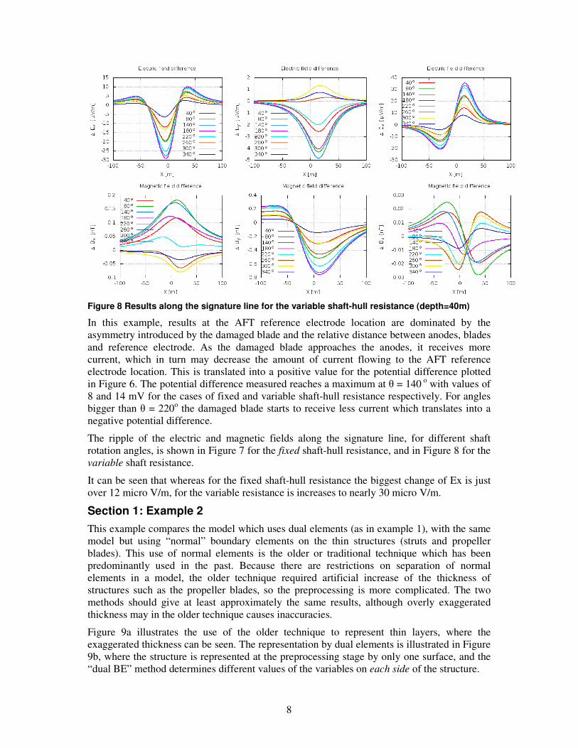
Figure 8 Results along the signature line for the variable shaft-hull resistance (depth=40m)
In this example, results at the AFT reference electrode location are dominated by the
asymmetry introduced by the damaged blade and the relative distance between anodes, blades
and reference electrode. As the damaged blade approaches the anodes, it receives more
current, which in turn may decrease the amount of current flowing to the AFT reference
electrode location. This is translated into a positive value for the potential difference plotted
in Figure 6. The potential difference measured reaches a maximum at θ = 140 o
with values of
8 and 14 mV for the cases of fixed and variable shaft-hull resistance respectively. For angles
bigger than θ = 220o the damaged blade starts to receive less current which translates into a
negative potential difference.
The ripple of the electric and magnetic fields along the signature line, for different shaft
rotation angles, is shown in Figure 7 for the fixed shaft-hull resistance, and in Figure 8 for the
variable shaft resistance.
It can be seen that whereas for the fixed shaft-hull resistance the biggest change of Ex is just
over 12 micro V/m, for the variable resistance is increases to nearly 30 micro V/m.
Section 1: Example 2
This example compares the model which uses dual elements (as in example 1), with the same
model but using “normal” boundary elements on the thin structures (struts and propeller
blades). This use of normal elements is the older or traditional technique which has been
predominantly used in the past. Because there are restrictions on separation of normal
elements in a model, the older technique required artificial increase of the thickness of
structures such as the propeller blades, so the preprocessing is more complicated. The two
methods should give at least approximately the same results, although overly exaggerated
thickness may in the older technique causes inaccuracies.
Figure 9a illustrates the use of the older technique to represent thin layers, where the
exaggerated thickness can be seen. The representation by dual elements is illustrated in Figure
9b, where the structure is represented at the preprocessing stage by only one surface, and the
“dual BE” method determines different values of the variables on each side of the structure.

9
Figure 9 Traditional technique and dual element representation of thin structures
Figure 10 Comparison of potentials when using dual elements and the traditional technique
The drawbacks of the older technique are mainly the complication of the definition of the
geometry and the mesh together with a generally increased number of elements. In addition,
insulating boundary conditions should generally be applied to the through-thickness sides,
making the preprocessing stage more laborious. Because of the need to maintain reasonable
mesh grading, the size of the exaggerated thickness introduces a constraint on the nearby
element sizes.
The use of dual elements avoids the previous drawbacks, as the geometry definition is
simpler, the boundary conditions are more easily applied and there is no limitation on the size
of elements on the surface.
Figure 11 Axial Electric Field (left) and Transverse Magnetic Field (right) along the signature line using dual elements and the traditional technique are identical in these plots
To compare the two methods, results obtained for the model described in example 1 in which
the blades and struts have been represented by dual elements are here compared with results
obtained using the older approach to defining the thin structures. The difference of results is
negligible as can be seen in Figure 10 which shows contour plots of potential at the initial
angle θ=0.
Figure 11 compares the axial electric field and transverse magnetic field at a specific shaft
rotation angle using duals and the older technique to represent thin structures. Again the
results are very similar.
10
SECTION 2. Simplified modelling of UEP in electrolyte with depth-varying conductivity
The standard BEM solves homogeneous electrolytes, so for non-homogeneous conditions a multi-domain (MD) technique must be adopted. This section shows use of an alternative “multi-layer” approach which uses a single domain to represent stratified electrolyte, using a
special Green’s function given by: ∑= +−
=
exp
14
1),,,(
N
k ijji
ijml
m
ji nmGgxx
xxα
πσ, which can be
regarded as a weighted method of images.
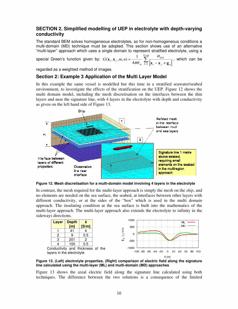
Section 2: Example 3 Application of the Multi Layer Model
In this example the same vessel is modelled but this time in a stratified seawater/seabed
environment, to investigate the effects of the stratification on the UEP. Figure 12 shows the
multi domain model, including the mesh discretisation on the interfaces between the thin
layers and near the signature line, with 4 layers in the electrolyte with depth and conductivity
as given on the left hand side of Figure 13.
Figure 12. Mesh discretisation for a multi-domain model involving 4 layers in the electrolyte
In contrast, the mesh required for the multi-layer approach is simply the mesh on the ship, and
no elements are needed on the sea surface, the seabed, at interfaces between other layers with
different conductivity, or at the sides of the “box” which is used in the multi domain
approach. The insulating condition at the sea surface is built into the mathematics of the
multi-layer approach. The multi-layer approach also extends the electrolyte to infinity in the
sideways directions.
Figure 13. (Left) electrolyte properties. (Right) comparison of electric field along the signature line calculated using the multi-layer (ML) and multi-domain (MD) approaches
Figure 13 shows the axial electric field along the signature line calculated using both
techniques. The difference between the two solutions is a consequence of the limited
Layer Depth [m]
k [S/m]
1 41 4
2 9 0.5
3 201 2
4 100 0.5
Conductivity and thickness of the layers in the electrolyte

11
sideways extent of the multi domain model (200m wide) and the infinite sideways extent of
the multi layer model.
Conclusions
New developments have been presented demonstrating the sophistication of modelling
techniques in predicting the real behaviour of ships protected by ICCP systems. Thus
providing a tool for the designer of the corrosion control system to predict the impact of
design concepts on the protection provided to the ship hull, its associated corrosion related
signature and the robustness of the design.
It has been shown that BEM simulation which includes the real shape of the propellers and
the full details of the supply/return circuit can exhibit effects of shaft rotation both on hull
potentials and on UEP and CRM signatures.
Some advantages of the multi layer method have been demonstrated for calculation of UEP.
In Litoral waters the sea bed can be easily modelled and in deep water vertical variation of
resistivity can be simulated without extra modelling effort. Mesh size is considerably reduced,
and sensors can easily be positioned close to the seabed.
References
[1] A. B Peratta, J. M W Baynham, and R. A. Adey. A Computational Approach for
Assessing Coating Performance in Cathodically Protected Transmission Pipelines.
CORROSION 2009, Paper 6595 Atlanta, Georgia. NACE International 2009.
[2] DeGiorgi VG, Kee A. and Thomas ED. “Characterization accuracy in modelling of
corrosion systems”. Proceedings of the 15th
Int. Conference on Boundary Element Methods,
BEM XV, Worcester Polytechic Institute, Worcester, Massachusetts, USA, 10-13 Aug.1993
[3] R.A. Adey, J. Baynham. Design and optimization of cathodic protection systems using
computer simulation. CORROSION 2000, Paper 723. Houston, Texas. NACE Int., 2000.
[4] Andres B Peratta, John M W Baynham, and Robert A. Adey . Advances In Cathodic
Protection Modelling of Deep Well Casings In Multi-Layered Media. CORROSION 2009,
Paper 6555 Atlanta, Georgia. NACE International 2009.
[5] Robert A. Adey and Seyyed Niku. Computer Modelling of Galvanic Corrosion, in
“Galvanic Corrosion”. Harvey P. Hack, editor. ASTM Committee G-1 on Corrosion of
Metals. ASTM International, 1988
[6] Pierre R. Roberge. “Corrosion Engineering. Principles and Practice”. McGraw-Hill (2008)
[7] C.A. Brebbia, J.C.F. Telles and L.C. Wrobel. Boundary Element Techniques – Theory and
Application in Engineering. Springer Verlag Berlin, Heidelberg NY, Tokyo. 1984.
[8] R. A.Adey, J. Baynham, R. Jacob. Prediction of Interactions between FPSO and Subsea
Cathodic Protection Systems. Corrosion 2008, Paper 08546, NACE International 2008.
[9] Robert A Adey, John Baynham. Methods of Optimisation and Control of Corrosion
Related Electric Fields. Marelec 1999.
[10] E Santana Diaz, R Adey, J Baynham,Y H Pei. Optimisation of ICCP systems to
minimise electric signatures. Marelec 2001.
[11] JMW Baynham, R A Adey. Simulating the Transient Response of ICCP Control
Systems. Marelec 2004.
[12] Ernesto Santana-Diaz ,Robert Tims. A Complete Underwater Electric and Magnetic
Signature Scenario Using Computational Modelling. Marelec 2006.

12
[13] DeGiorgi VG and Hamilton CP. “Coating integrity effects on impressed current cathodic
protection system parameters”. Proceedings of the 17th International Conference on
Boundary Element Methods, 1995