Model 560 Series NBX®/UPS Shutdown Interface User Manual · Unique Micro Design ... Engineering IT...
16
Unique Micro Design ... Engineering IT Solutions Model 560 Series NBX®/UPS Shutdown Interface User Manual Document Reference : DOC-M560-UM UMD Part Number : 9-0560-993-3 Issue : Issue 2 Revision : 10/10/2003 © 2003 Unique Micro Design All rights reserved .
Transcript of Model 560 Series NBX®/UPS Shutdown Interface User Manual · Unique Micro Design ... Engineering IT...

Unique Micro Design
... Engineering IT Solutions
Model 560 Series
NBX®/UPS Shutdown Interface
User Manual
Document Reference : DOC-M560-UM
UMD Part Number : 9-0560-993-3
Issue : Issue 2
Revision : 10/10/2003
© 2003 Unique Micro Design
All rights reserved .

2
Model 560 User Manual ——
Date Issue Comments
18/09/2002 1 Issue 1
10/10/2003 2 Connector Assignment changed
PCB Rev. 2 (3-2057-002-3)
Revision History
NBX® + SuperStack® 3 are registered trade marks of
3 Com Corporation

—— Model 560 User Manual
3
1. Introduction
1.1 Scope
This manual provides information for the Unique Micro Design
Model 560 NBX®/UPS Shutdown Interface.
1.2 Overview
The Unique Micro Design Model 560 NBX®/UPS Shutdown
Interface provides an orderly shutdown of NBX®100/25 and
SuperStack® 3, when an input from a UPS indicates low battery.
The orderly shutdown of the NBX®, prevents database
corruption.
The M560 holds the NBX® in a “ReBoot” state until the UPS
indicates power has returned to normal.
Important Note
The NBX® telephone system is very sensitive to electrical noise
on its inputs. Unique Micro Design recommend surge protectors
on all interfaces and proper grounding of the system enclosure.
It is also recommended that regular backup procedures are
implemented.
4
Model 560 User Manual ——
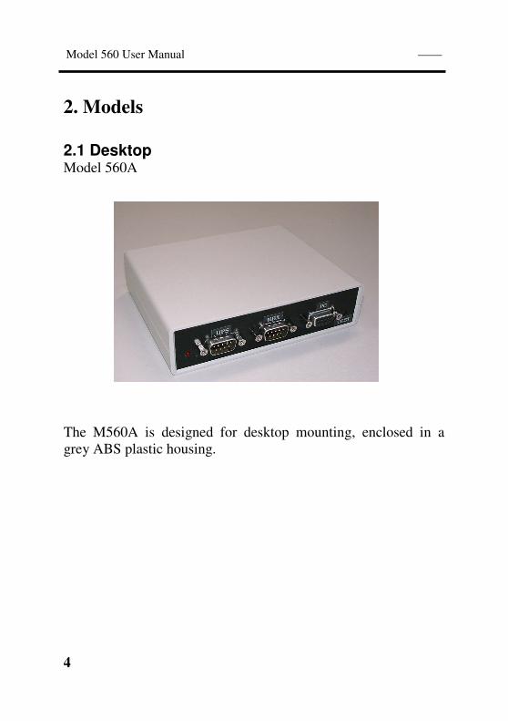
2. Models
2.1 Desktop Model 560A
The M560A is designed for desktop mounting, enclosed in a
grey ABS plastic housing.
—— Model 560 User Manual
5
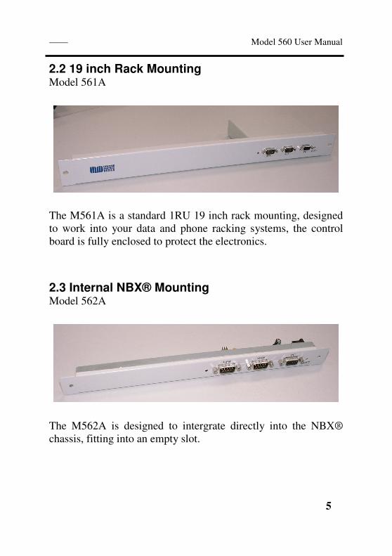
2.2 19 inch Rack Mounting Model 561A
The M561A is a standard 1RU 19 inch rack mounting, designed
to work into your data and phone racking systems, the control
board is fully enclosed to protect the electronics.
2.3 Internal NBX® Mounting Model 562A
The M562A is designed to intergrate directly into the NBX®
chassis, fitting into an empty slot.
6
Model 560 User Manual ——
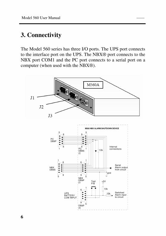
3. Connectivity
The Model 560 series has three I/O ports. The UPS port connects
to the interface port on the UPS. The NBX® port connects to the
NBX port COM1 and the PC port connects to a serial port on a
computer (when used with the NBX®).
CO
UN
TE
R S
INK
SC
RE
WS
+
6
95
1
1
5NBXDB9P J2
6
Internalconnections
10k
9
PCDB9SJ1
gnd
SerialAlarm outputfrom circuit
1
5DB9P J3
6
9
+5V
10k
10k SwitchedAlarm inputto circuit
TestP/B
6
95
1
1
5
6
9
PCDB9P
NBXDB9S
UPSBATTERYLOW INPUT
M560 NBX ALARM SHUTDOWN DEVICE
J2
J3
J4

—— Model 560 User Manual
7
The M560 is designed to “wedge” between a PC and the NBX®
serial port COM1 (when a computer is used), the shutdown data
is sent directly to the NBX® port. The UPS port connects to the
interface port on the UPS, this series model is designed for the
APC brand, but there are many factory options available (contact
our Technical Department: “[email protected]” for
further information).
Connecting the M560 series NBX®/UPS Shutdown Interface
8
Model 560 User Manual ——
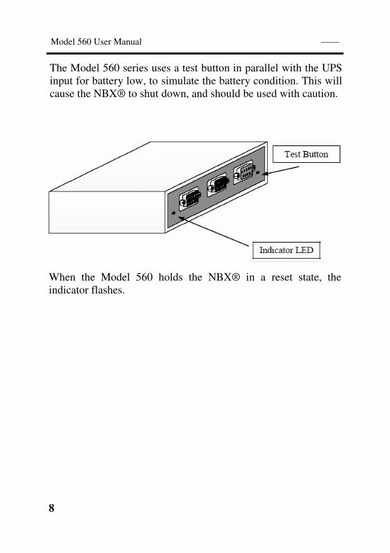
The Model 560 series uses a test button in parallel with the UPS
input for battery low, to simulate the battery condition. This will
cause the NBX® to shut down, and should be used with caution.
Indicator LED
Test Button
LED
When the Model 560 holds the NBX® in a reset state, the
indicator flashes.
—— Model 560 User Manual
9
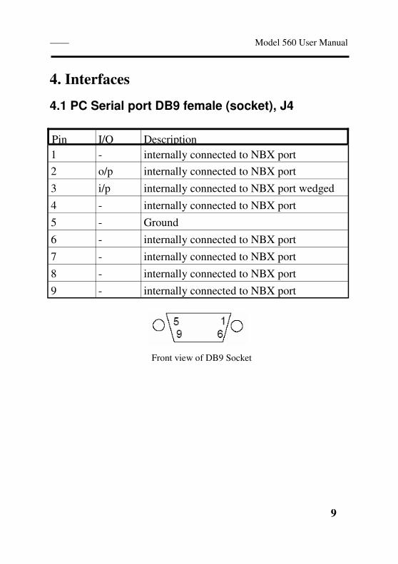
4. Interfaces
4.1 PC Serial port DB9 female (socket), J4
Pin I/O Description
1 - internally connected to NBX port
2 o/p internally connected to NBX port
3 i/p internally connected to NBX port wedged
4 - internally connected to NBX port
5 - Ground
6 - internally connected to NBX port
7 - internally connected to NBX port
8 - internally connected to NBX port
9 - internally connected to NBX port
Front view of DB9 Socket
10
Model 560 User Manual ——
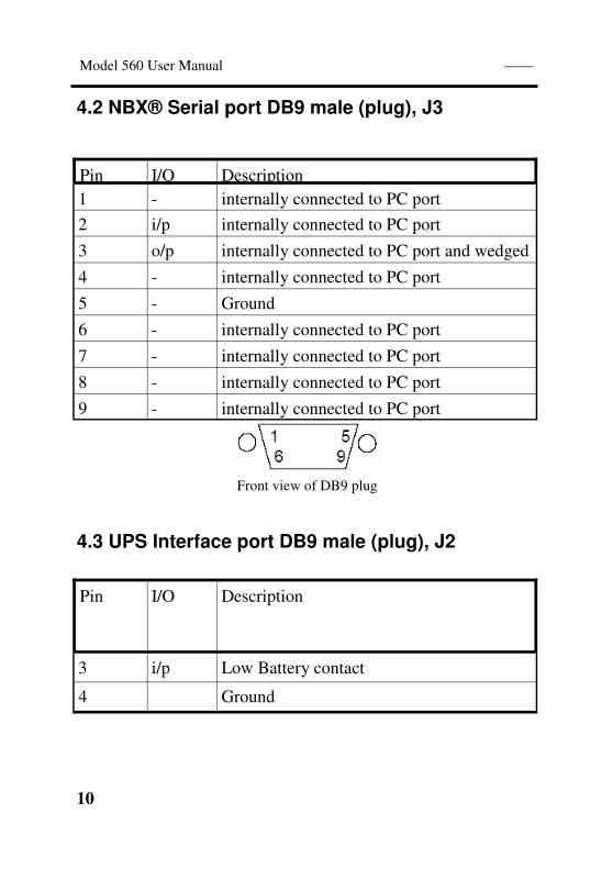
Front view of DB9 plug
4.2 NBX® Serial port DB9 male (plug), J3
Pin I/O Description
1 - internally connected to PC port
2 i/p internally connected to PC port
3 o/p internally connected to PC port and wedged
4 - internally connected to PC port
5 - Ground
6 - internally connected to PC port
7 - internally connected to PC port
8 - internally connected to PC port
9 - internally connected to PC port
4.3 UPS Interface port DB9 male (plug), J2
Pin I/O Description
3 i/p Low Battery contact
4 Ground
—— Model 560 User Manual
11
The Unique Micro Design Model 560 NBX®/UPS Shutdown
Interface provides an orderly shutdown of NBX®100/25 and
SuperStack® 3, when an input from a UPS indicates low battery.
The orderly shutdown of the NBX®, prevents database
corruption.
When the input from the UPS indicates the battery is low, the
M560 sends the NBX® a “ReBoot” command. The LED
indicator flashes each half second to indicate this process, the
M560 then holds the NBX® from restarting until the UPS input
has changed state (ie UPS is back to normal operation).
The M560 will then send the restart command to the NBX®.
5. Operation

12
Model 560 User Manual ——
Physical Dimensions 140 x 110 x 35 mm
Desktop Model Enclosure Moulded ABS plastic
Colour grey
Power Source via parasitic from handshake lines on NBX ® and PC
Voltage 5 Volts
Input Current 1.2 mA (nominal)
I/O Ports UPS DB9 plug
NBX DB9 plug
PC DB9 socket
6. Specifications
—— Model 560 User Manual
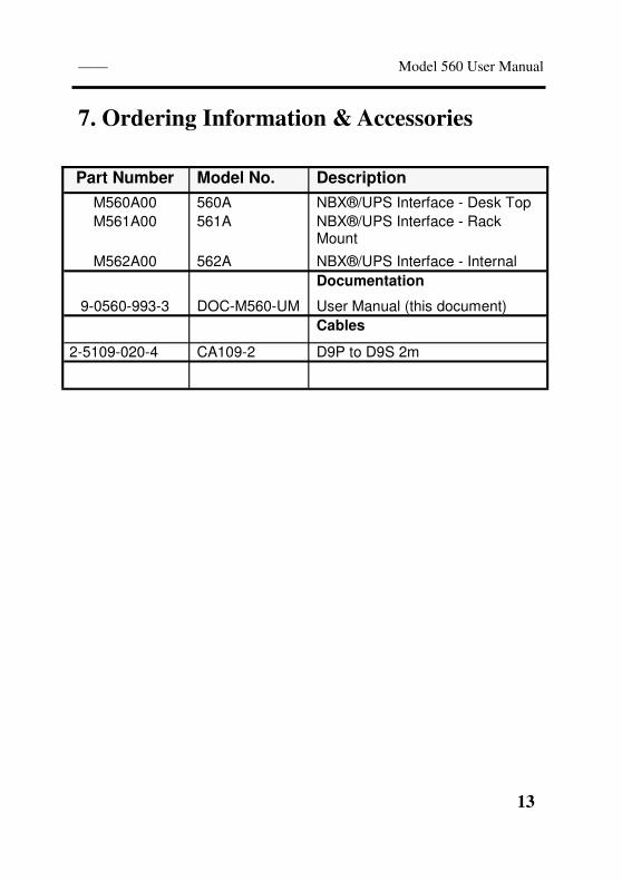
13
Part Number Model No. Description
M560A00 560A NBX®/UPS Interface - Desk Top
M561A00 561A NBX®/UPS Interface - Rack Mount
M562A00 562A NBX®/UPS Interface - Internal
Documentation
9-0560-993-3 DOC-M560-UM User Manual (this document)
Cables
2-5109-020-4 CA109-2 D9P to D9S 2m
7. Ordering Information & Accessories

14
Model 560 User Manual ——

—— Model 560 User Manual
15

16
Model 560 User Manual —— ... Engineering IT Solutions ...
Unique Micro Design Pty Ltd ( ACN 007 419 490 ) 200 Wellington Road, Clayton VIC 3168, Australia http://www.umd.com.au
Tel: +61-3-9582-7000 Fax: +61-3-9582-7001
Email: [email protected]