MICROBEARINGS ΠNEW TRIBOLOGY PROBLEMS AND...
21
5-2009 T R I B O L O G I A 45 Jan KICIŃSKI * MICROBEARINGS NEW TRIBOLOGY PROBLEMS AND CHALLENGES MIKROŁOŻYSKA NOWE PROBLEMY I WYZWANIA W TRIBOLOGII Key-words: rotor dynamics, nonlinear vibrations, hydrodynamic instability, heuristic problems, computer simulation Słowa kluczowe: dynamika wirników, drgania nieliniowe, niestabilność hydrodynamiczna, zagadnienia heurystyki, symulacje komputerowe Summary Nonlinear forms of vibrations in rotors dynamics, especially after exceed- ing the stability limit, as well as the assessment of not precise and ran- domly variable input parameters still constitute the research subject in many institutions all over the world. The results of investigations of the high-speed rotor of a micro turbine being an element of the micro power plant in dispersed power engineering based on renewable energy sources * Institute of Fluid-Flow Machinery Polish Academy of Sciences, Fiszera 14, 80-952 Gdansk, Poland, University of Warmia and Mazury, Olsztyn, Poland.
Transcript of MICROBEARINGS ΠNEW TRIBOLOGY PROBLEMS AND...

5-2009 T R I B O L O G I A 45
Jan KICIŃSKI*
MICROBEARINGS � NEW TRIBOLOGY PROBLEMS AND CHALLENGES
MIKROŁOŻYSKA � NOWE PROBLEMY I WYZWANIA W TRIBOLOGII
Key-words:
rotor dynamics, nonlinear vibrations, hydrodynamic instability, heuristic problems, computer simulation
Słowa kluczowe:
dynamika wirników, drgania nieliniowe, niestabilność hydrodynamiczna, zagadnienia heurystyki, symulacje komputerowe
Summary
Nonlinear forms of vibrations in rotors dynamics, especially after exceed-ing the stability limit, as well as the assessment of not precise and ran-domly variable input parameters still constitute the research subject in many institutions all over the world. The results of investigations of the high-speed rotor of a micro turbine being an element of the micro power plant in dispersed power engineering based on renewable energy sources * Institute of Fluid-Flow Machinery Polish Academy of Sciences, Fiszera 14, 80-952
Gdansk, Poland, University of Warmia and Mazury, Olsztyn, Poland.

T R I B O L O G I A 5-2009 46
are presented in the paper. The basic problem of such devices is to assure a stable rotor operation within the entire range of rotational speeds. Foil bearings and special rotor structure were applied. It turned out that the situation, in that the rotor – after loosing its stability – stabilizes again when the rotational speed increases, is possible. This is a new phenome-non determined by the author as ‘multiple whirls’. Possibilities of stabi-lizing the situation by the application of hybrid lubrication and siphon pockets are also presented in the paper. Another topic discussed in the hereby paper is an assessment of the influence of a random character of certain input data – in this case – changes of external excitations of the system. This problem is related to the so-called heuristic models often placed in opposition to widely used algorithmic models. The obtained results indicate different influence of disturbances depending on the sys-tem working conditions. After exceeding the stability limit, it means in a highly nonlinear operation range, the influence of disturbances signifi-cantly decreases. It is rather unexpected result. Research tools such as computer series codes and the method of their experimental verification are also included in the paper.
INTRODUCTORY REMARKS
Cogeneration is a process of simultaneous generation of heat and electric current (so called CHP systems). If this process takes place in low-power machines (between several and several tens of KW, sometimes up to several hundreds of kW), this provides opportunities for so called small-scale dispersed cogeneration, the idea of which consists in building power centres for particular individual receivers. Of high profitability in the dispersed cogeneration is the use of renewable energy sources, bio-mass and biogas in particular, for feeding electrical appliances. The dis-persed cogeneration based on renewable energy sources defines present research trends in the European Union, and also in our country. This is in direct relation with the problems of ecological production of energy and energetic safety of the entire regions. That is why this subject matter is one of strategic research priorities in the country.
Key elements in the dispersed cogeneration system are micro power plants, i.e. microbearings and microturbines cooperating with ecological boilers. The term „microturbine” is not very adequate in the context of the dispersed cogeneration, although it is in common use. Here we talk

5-2009 T R I B O L O G I A 47
about the geometric scale of the turbine of an order of several to several tens of millimetres, rotational speed of an order of less than hundred thousand rev/min and power output from about ten KW to several hun-dreds KW. Perhaps in this case it would be more appropriate to intro-duce a term of “mesoscale”, the more so that the real “micro” scale of the turbine is of an order of a few millimetres. Thus we could define devel-opment tendencies as the way from MACRO, through MESO to MICRO scale, as is illustratively shown in Fig. 1 [L. 2�4]. In our further consid-erations we will use both the term of “mesoscale”, and a common defini-tion of a “micro power plant” in reference to the same class of power machines.
Safe operation of those machines brings new challenges for design-ers, operators, and research workers. The operation of a turbine at rota-tional speed of an order of several thousand rev/min, small external loads and small dimensions of the entire machine create serious problems with keeping stable operation of the system and securing relevant durability of its particular elements. Of particular importance here are the bearings, which should secure stable and safe operation of the entire machine. Numerous novel solutions are proposed in the form of low-friction polymer bearings, foil bearings, or various types of gas bearings. A concept which becomes more and more attractive takes into account low-boiling agent, which is normally used in the thermal cycle of the micro-turbine, as a lubricating liquid in the bearings (so called ORC based sys-tems). Such an approach provides opportunities for using hermetically tight closed systems. A method for increasing anti-vibrational resistance of slide bearings lubricated by low-boiling liquids, and thus reducing vibroacoustic threats, is increasing its damping abilities by relevant changes of the shape of the lubricating clearance during bearing operation and proper direction of heat flow and bush deformation. To allow study-ing these problems, bearing characteristics are to be modelled by ad-vanced thermal models and models taking into account thermoelastic deformations of the lubricating clearance.
On the other hand, continuous operation of the system close to the stability limit, or even after exceeding it, requires the use of nonlinear models for analysing rotor dynamics issues, as only these models allow tracing the process of rotor trajectory transformation and estimating the scale of potential threat. Moreover, possible faster propagation of rotor cracks, for instance, as a result of significantly increased number of fa-

T R I B O L O G I A 5-2009 48
tigue cycles, forces creating models taking into account this type of ma-terial imperfections. This means operating conditions, in which real tribology threat for these machines can have place. Of some importance is also the operation of these machines at low noise emission level, as, being parts of household equipment they could disturb the calm of the residents. As we can see, analysing the dynamic state of the �home� power plants requires qualitatively novel research tools.
The article presents results of the analysis of a microturbine in opera-tion (in the mesoscale), after exceeding the stability limit and taking into account thermoelastic deformations of bearing bushes. The analysis also includes the effect of possible rotor cracks. The studies were done using models and computer codes developed in IF-FM, Gdańsk.
Fig. 1. Tendencies in development of turbines from MACRO through MESO to
MICRO scale Rys. 1. Tendencje rozwoju turbin od skali MACRO poprzez MESO do MICRO
RESEARCH TOOLS AND THEIR VERIFICATION
The MESWIR computer code, based on nonlinear models of complex sys-tems rotor-bearings, was applied in research, Fig. 2. Theoretical models, basic equations as well as the system itself have been presented already several times during the conferences and in publications [L. 1, 2, 3]. Due to that and having in mind the paper space limitation and its different aims, the MESWIR series code will not be presented here in details. However,

5-2009 T R I B O L O G I A 49
it is worth mentioning that the most useful feature of this system is the possibility of description of the rotor machine state both in a linear and nonlinear range by means of the same tool, thereby describing new vibra-tion forms at transition the stability limit. The description capability of bearings of a complex geometry of oil clearance including foil bearings is also important. The MESWIR code was experimentally verified both at the research stand and with using real objects such as large power turbo-sets [L. 1].
Fig. 2. Basic modules and algorithms of the MESWIR series code [L. 1] applied in the hereby paper
Rys. 2. Podstawowe moduły i algorytm obliczeń systemu komputerowego MESWIR [L. 1] wykorzystywanego w niniejszej pracy

T R I B O L O G I A 5-2009 50
For the needs of the research, this system was coupled with commer-cial programs of the ABAQUS type to determine dynamic properties of the supporting structure and of the whole system. Thus, bearing and rotor characteristics (MESWIR system) as well as dynamic characteristics of supporting structure (ABAQUS system) were calculated in one iteration loop. However, this type of coupling requires additional verifying of such research tools. The photo of the testing stand operating in the diagnostics Laboratory of the Institute of Fluid-Flow Machinery, Polish Academy of Sciences, as well as the FEM discretisation of this system together with details concerning modeling of characteristic structural nodes such as fixing bolts or vibroinsulators is presented in Fig. 3.
Fig. 3. Photo of the testing stand and the FEM discretisation of rotor and sup-
porting structure (taking into account properties of coupling elements, vi-broinsulators and a concrete block [L. 2, 4]
Rys. 3. Zdjęcie stanowiska badawczego i dyskretyzacja MES wirnika i konstrukcji podpierającej z uwzględnieniem własności elementów łączących, wibroizolato-rów i bloku betonowego [L. 2, 4]
This is a system of a journal diameter d = 0.1 m, discs diameter
D = 0.4 m and length L = 3.2 m. Fig. 4 presents the experimental verifi-cation results done by a modal analysis with the application of PC CADA tools. As can be seen, the compatibility of results is quite satisfactory.
The situation is different in the case of experimental verification of dynamic flexibility coefficients. Obtaining a good compatibility – in such systems – is much more difficult and sometimes even impossible. This is

5-2009 T R I B O L O G I A 51
illustrated in Fig. 4. The experimental data were obtained by sinusoidal excitations of subsequent supports and recording the bearing bush dis-placements, whereas the theoretical data constitute the results of calcula-tions performed by means of the ABAQUS commercial software coupled with the MESWIR code. Regardless of such precise theoretical modeling of the entire system (Fig. 3), we did not manage to achieve sufficient compatibility of experimental and theoretical results – see: upper dia-grams in Fig. 5. After several tests, only when a crack of one of the fixing bolts was taken into account in calculations that the verification results improved – see: lower diagrams in Fig. 5. It occurred, that this bolt was actually quite loose and behaved as if being cracked. This example can serve as an excellent illustration of capabilities of the model based diag-nostics, since knowing the symptom we can – by means of the computer analysis – localize the defect.
Fig. 4. Results of the experimental verification performed by modal analysis for two main modes (PC CADA system was used in experiments � right-hand side) [L. 2, 4]
Rys. 4. Wyniki weryfikacji eksperymentalnej w zakresie analizy modalnej dla dwóch głównych modów (w badaniach eksperymentalnych wykorzystano system PC CADA – prawa strona) [L. 2, 4]
Research tools prepared and verified in such a way were applied in
the research constituting the basic contents of the hereby paper.

T R I B O L O G I A 5-2009 52
Fig. 5. Verification of dynamic flexibility coefficients for one bearing support of the system shown in Fig. 3. Experimental tests: excitations of one support by a sinusoidal exciter and measuring displacements. Theoretical investi-gations: calculations by the ABAQUS system coupled with the MESWIR series code. Upper diagram: calculations not taking into account any cracking (loosening). Lower diagram: calculations taking into account the crack of one bolt that fixes the frame [L. 2, 4]
Rys. 5. Weryfikacja dynamicznych współczynników podatności dynamicznej dla jednej z podpór łożyskowych układu z Rys. 2. Badania eksperymentalne: wymusze-nia na podporze wzbudnikiem sinusoidalnym i pomiar przemieszczeń, badania teoretyczne: obliczenia systemem ABAQUS sprzężonym z systemem MESWIR. Rysunek górny: obliczenia bez uwzględnienia pęknięcia (poluzowania) jednej ze śrub mocujących, rysunek dolny: obliczenia uwzględniające pęknięcie [L. 2, 4]
STABILITY TESTING OF HIGH-SPEED ROTORS. PHENOMENON OF �MULTIPLE WHIRLS�
Problems related to ecological energy generation at a small and dispersed scale have become especially actual in recent years. A dispersed power
5-2009 T R I B O L O G I A 53
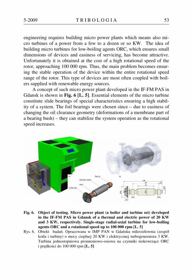
engineering requires building micro power plants which means also mi-cro turbines of a power from a few to a dozen or so KW. The idea of building micro turbines for low-boiling agents ORC, which ensures small dimensions of devices and easiness of servicing, has become attractive. Unfortunately it is obtained at the cost of a high rotational speed of the rotor, approaching 100 000 rpm. Thus, the main problem becomes ensur-ing the stable operation of the device within the entire rotational speed range of the rotor. This type of devices are most often coupled with boil-ers supplied with renewable energy sources.
A concept of such micro power plant developed in the IF-FM PAS in Gdansk is shown in Fig. 6 [L. 5]. Essential elements of the micro turbine constitute slide bearings of special characteristics ensuring a high stabil-ity of a system. The foil bearings were chosen since – due to easiness of changing the oil clearance geometry (deformations of a membrane part of a bearing bush) – they can stabilize the system operation as the rotational speed increases.
Fig. 6. Object of testing. Micro power plant (a boiler and turbine set) developed in the IF-FM PAS in Gdansk of a thermal and electric power of 20 KW and 3 KW, respectively. Single-stage radial-axial turbine for low-boiling agents ORC and a rotational speed up to 100 000 rpm [L. 5]
Rys. 6. Obiekt badań. Opracowana w IMP PAN w Gdańsku mikrosiłownia (zespół kotła i turbiny) o mocy cieplnej 20 KW i elektrycznej turbogeneratora 3 KW. Turbina jednostopniowa promieniowo-osiowa na czynniki niskowrzące ORC i prędkości do 100 000 rpm [L. 5]

T R I B O L O G I A 5-2009 54
Fig. 7 presents a sketch of bearings applied in the object shown in Fig. 6 and the FEM discretisation of the foil system in order to calculate a static substitute stiffness of a bearing, while Fig. 8 presents a verification of the obtained results.
Fig. 7. Sketch of foil bearings applied in a micro turbine from the object shown in Fig. 6 (of a journal diameter 10 mm ) and the FEM discretisation of an in-ner foil, membrane and outer foil � in order to calculate the substitute stiffness of the bearing bush [L. 5]
Rys. 7. Szkic łożysk foliowych zastosowanych w mikroturbinie z obiektu na Rys. 5 (o średnicy czopa 10 mm) oraz dyskretyzacja MES folii wewnętrznej, mem-brany i folii zewnętrzej w celu obliczenia sztywności zastępczej panwi [L. 5]
Fig. 8. Verification of a static substitute stiffness of the foil bearing bush. Model and calculations [L. 5], experiment according to [L. 6]
Rys. 8. Weryfikacja statycznej sztywności zastępczej panwi łożyska foliowego. Model i obliczenia własne [L. 5], eksperyment wg [L. 6]

5-2009 T R I B O L O G I A 55
Compatibility of theoretical and experimental results is considered to be satisfactory. The notion of the substitute stiffness is essential for the calculation capabilities of the MESWIR code (multiple calculations in one iteration loop).
The system assumed for testing consisted of a rotor (with one disc and a generator) placed on two foil bearings of dimensions shown in Fig. 6. A low-boiling medium ORC was used as bearings lubricant, which significantly simplifies construction of the whole micro power plant. Typical values of the possible unbalancing of a rotor disc (as an excitation force) were assumed as well as some parametric values of damping the foil bearing bush and supporting structure (from the material data sheets).
The calculation results in the form of amplitude – speed characteris-tics within the speed range up to 100 000 rpm are presented in Fig. 9.
Fig. 9. Amplitude � speed characteristics of the rotor from the micro turbine (shown in Fig. 6) calculated for the relative vibrations of a journal and foil bearing bush. Illustration of the �multiple whirls� phenomenon in bearing No. 2 (repeated processes of formation and decaying of high amplitude zones caused by a hydrodynamic instability)
Rys. 9. Charakterystyki amplitudowo-prędkościowe wirnika mikroturbiny z Rys. 6 obliczone dla drgań względnych czopa i panwi łożysk foliowych. Ilustracja zjawiska „wirów wielokrotnych” w łożysku 2 (powtarzające się procesy po-wstawania i zaniku zakresów dużych amplitud spowodowanych niestabilnością hydrodynamiczną)
The attention is called to quite different operation of bearing No. 1
(at the disc) and bearing No. 2 (free end). While bearing No. 1 is stable within the entire range of rotational speeds, bearing No. 2 exhibits two

T R I B O L O G I A 5-2009 56
characteristic zones of exceptionally high vibration amplitudes exceeding 70% of a bearing clearance. To identify this phenomenon and to exclude common resonance, the shape of relative displacement trajectories of the journal and bearing bush in these zones were analyzed. The calculation results for the first zone and after passing through it are presented in Fig. 10.
Analysis of Figure 10 explicitly indicates that the displacement tra-jectory of bearing No. 2 at a rotational speed of 25 000 rpm (the first zone of high amplitudes) has features characteristic for the expanded hydro-dynamic instability, the so-called ‘whip’. The ‘whip’ means – in this case – a developed form of whirls of a lubricating medium within the lubrica-tion clearance. This is pointed out by double shaft rotations (it means a vector of external excitations) falling to one full precession, which cre-ates 2 phase markers (FM) on the trajectory. Actually, there are three markers since points for 0 and 720 degrees overlap each other, which not always happens. This means, that the same positions of the excitation force vectors (horizontally to the right: TAL = 0, 360 and 720 degrees) correspond to different positions on the journal trajectory within the bear-ing clearance.
However, the most unexpected is the observation that after the sys-tem has exceeded the first zone of hydrodynamic instability (which means the first ‘whip’) the system returns to a stable operation of bearing No. 2 (it means to the typical situation, in which one phase marker on the trajectory corresponds to one rotation of the excitation vector). The situa-tion remains a stable one up to the rotational speed of approximately 65 000 rpm. After the system has exceeded this speed a rapid instability (‘whip’) occurs again followed by a subsequent calming down.
Thus, we are dealing here with a multiple ‘whip’ of a lubricating medium, understood as formation and decaying of the hydrodynamic in-stability as the rotational speed of the rotor increases. If we assume a stiff bearing bush we are unable to model the phenomenon. This allows to assume that variable deformations of the foil bearing bush (corresponding to the turbine rotational speed increase) are responsible for such process. Since this phenomenon is not known – from the references – to the au-thor of this paper he suggests to call it ‘multiple whirls’. The phenome-non of ‘multiple whirls’ has been quite often observed in practice by ex-ploitation crews of large power plants. Small oil whirls were formed and then disappearing on one of the recorded bearings and this did not cause

5-2009 T R I B O L O G I A 57
any instability of the entire system. Unfortunately those results have not been published. In our case, it means in the case of a small power micro turbine, we are dealing with large whirls i.e. whips, however, it is a dif-ferent magnitude scale and a different rotational speed range.
Fig. 10. Displacement trajectories of journal of bearing No. 1 and 2 calculated for the first high amplitudes zone (25 000 rpm ) and in the transient pe-riod (50 000 rpm). Image of the first hydrodynamic �whip� in the trajec-tory � 2 phase markers FM (upper right-hand side trajectory). Broken line indicates deformations of the bearing inner foil
Rys. 10. Trajektorie przemieszczeń czopów łożyska 1 i łożyska 2 obliczone dla pierwszego zakresu wysokich amplitud (25 000 rpm ) i w okresie przejścio-wym (50 000 rpm). Obraz pierwszego „bicia” hydrodynamicznego na trajek-torii – 2 znaczniki fazy FM (górna prawa trajektoria). Linia przerywana oznacza deformacje folii wewnętrznej łożyska

T R I B O L O G I A 5-2009 58
A zone of ‘multiple whirls’ is very interesting from the point of view of the hydrodynamic pressure distribution. The very fact of existing 2 phase markers corresponds to the situation, in which for the same posi-tion of the exciting force vector (TAL = 0 and 360 degrees) we have two different journal positions on the trajectory and two different pressure distributions in the bearing. This is illustrated in Fig. 11.
Fig. 11. Pressure distribution calculated for various positions of phase markers within a zone of �multiple whirls� for the same position of the excitation force vector (horizontally to the right, it means for TAL = 0 and 360 de-grees)
Rys. 11. Rozkłady ciśnienia obliczone dla różnych położeń znaczników fazy w obsza-rze „wirów wielokrotnych” dla tego samego położenia wektora sił wymusza-jących (poziomo w prawo, czyli dla TAL = 0 i 360 stopni)

5-2009 T R I B O L O G I A 59
A question arises: is there any method enabling improvement of the dynamic state of a micro turbine – in this case – characteristics of bearing No. 2? Various possibilities were considered. One of them was a concept of a hybrid lubrication with the application of siphon pockets. Several examples have been analyzed. The most profitable was the case with 4 siphon pockets (2 in the upper part and 2 in the lower part of the bearing bush – Fig. 12) and siphon pressure at the level of 0.01 MPa. The calcu-lation results are presented in Fig. 12. Comparing these results with the amplitude-speed characteristics for bearing No. 2 in Fig. 9, we will im-mediately notice that ‘multiple whirls’ disappeared and vibration ampli-tudes are significantly lower in the entire range of rotational speeds. This observation might suggests directions of further research, however, solu-tions based on hybrid lubrication – in the micro turbine case – signifi-cantly complicate design and exploitation side of the problem.
Fig. 12. Influence of siphon pockets and siphon pressure for the course of vibra-tion amplitudes and pressure distribution � for bearing No. 2 of the ob-ject shown in Fig. 6. 4 siphon pockets were applied (upper part of the Figure) and pressure = 0.01 MPa
Rys. 12. Wpływ kieszeni lewarowych i ciśnienia lewarowego na przebieg amplitud drgań i rozkłady ciśnienia dla łożyska 2 obiektu z Rys. 6. Zastosowano 4 kieszenie lewarowe (szkic w górnej części rysunku) i ciśnienie 0,01 MPa

T R I B O L O G I A 5-2009 60
STOCHASTIC VARIABILITY OF INPUT DATA IN HEURISTIC MODELING OF ROTORS
A classic, traditionally applied for many years, approach to the state modeling of various kinds of machines is the algorithmic approach, i.e. the one in which for the known set of input data we obtain the same, pre-cisely repeatable, set of output data (results). This is the obvious conse-quence of calculation capability of computers and the applied programs. However, this type of ‘traditional’ research tools, often highly advanced and applicable in practice, are neither able to correct the already intro-duced data nor to modify the assumed model depending on external con-ditions during the calculation procedure being in progress.
Meanwhile natural phenomena and a human nature (and thereby ob-jects created by it) are of a heuristic character, which means possible feedbacks occurring in processes, intrinsic data and the previously as-sumed methodology of state assessment – corrections. It also means the necessity of taking into account influences of various errors and the un-certainty of input data, what is often intuitively done.
It is worth to mention that the trial of heuristic modeling means the necessity of having highly advanced ‘traditional’ research tools. The so called nonlinear description is extremely important since heuristic mod-els are nonlinear by nature. Another substantial feature is the possibility of a smooth transition from the linear to nonlinear description applying the same research tools (the Superposition Principle cannot be used in this case). In consideration of the above, the MESWIR series code was applied in investigations. Fig. 13 presents the object used in tests as well as the concept of random changes of external excitation forces acting on a rotor disc. The randomness of changes was assumed (random-number generator was applied) although within limits +/-∆P in proportion to the basic value P. Calculations were performed for different ∆P values simu-lating in this way various possible situations (e.g.: displacement of rotat-ing masses, influence of magnetic fields, etc.).
External rotating excitation forces, which can randomly change within limits +/-20 % in proportion to the basic value, P, was assumed for the analysis, Fig. 13. The calculation results for the rotor shaft rota-tional speed from 300 rpm to 5550 rpm are shown in Fig. 14 and 15 [L. 7]. The trajectory of the rotor centre loaded by a constant force (basic) – rotating synchronously – is shown for the comparison on the left-hand

5-2009 T R I B O L O G I A 61
side of each Figure, whereas the trajectory of the rotor loaded by ran-domly changing force – within limits +/-∆P = 20% in proportion to the basic force P – is shown on the right-hand side of the Figure. Images of trajectories in co-ordinate systems related to the maximum value of bear-ing clearance are placed in the upper part, while images of trajectories magnified as much as possible to exhibit clearly the phenomena are shown in the lower part of the Figure.
Fig. 13. Object of investigations: twin-support, symmetric rotor of a shaft
diameter of 0.1 m, disc diameter 0.4 m, shaft length 1.4 m and a mass of 179 kg. Classic, cylindrical slide bearings lubricated by machine oil were used. The stochastic variability of an external excitation force within lim-its +/-∆P = 20% in proportion to the constant (basic) value P was as-sumed
Rys. 13. Obiekt badań: dwupodporowy, symetryczny wirnik o średnicy wału 0,1 m, średnicy tarczy 0,4 m, długości wału 1,4 m i masie 179 kg. Zastosowano kla-syczne, cylindryczne łożyska ślizgowe smarowane olejem maszynowym. Za-łożono stochastyczną zmienność zewnętrznej siły wymuszającej w granicach +/- ∆P= 20% w stosunku do wartości stałej (bazowej) P
The analysis of the Figure indicates that influence of randomly
changing values of the external excitation force is significant in the case of small rotational speeds of the rotor. When the speed increases this in-fluence diminishes, what can be explained by the influence of rotor iner-tial forces generally attenuating a time-history. At the very stability limit a certain increase in the trajectory disturbance can be observed. How-ever, disturbances caused by the stochastic variability of input data decay

T R I B O L O G I A 5-2009 62
Fig. 14. Displacement trajectories of the rotor centre � within a stable operation range � calculated for the constant excitation force (basic) P (part A) and for the randomly changing � within limits +/-∆P = 20 % (part B) shown at the background of the rotor amplitude-frequency response [L. 7]
Rys. 14. Trajektorie przemieszczeń środka wirnika w stabilnym zakresie pracy obli-czone dla stałej siły wymuszającej (bazowej) P (część A rysunku) oraz dla si-ły losowo zmiennej w granicach +/- ∆P= 20% (część B rysunku) na tle cha-rakterystyki amplitudowo-częstotliwościowej wirnika [L. 7]
Fig. 15. Displacement trajectories of the rotor centre after the system exceeded the stability limit calculated for the constant basic force P (part A) and for the randomly changing � within limits +/-∆P = 20 % (part B) shown at the background of the rotor amplitude-frequency response [L. 7]
Rys. 15. Trajektorie przemieszczeń środka wirnika po przekroczeniu granicy stabilno-ści obliczone dla stałej siły bazowej P (część A rysunku) oraz dla siły loso-wo zmiennej w granicach +/- ∆P= 20% (część B rysunku) na tle charaktery-styki amplitudowo-częstotliwościowej wirnika [L. 7]
when the rotor rotational speed increases, it means when the hydrody-namic instability develops Fig. 15. This is rather a startling result, since it could have been expected that such perturbations – after exceeding the

5-2009 T R I B O L O G I A 63
stability limit – would intensify the instability of the entire system since it has been already unstable. Similar conclusions were found when investi-gations were performed for various ∆P values and various algorithms of random excitations. Thus, a system defect in the form of the hydrody-namic instability attenuates to a certain degree the defect caused by sto-chastic effects of input data. It is an interesting observation resulting from the performed research.
FINAL CONCLUSIONS
The phenomenon of ‘multiple whirls’ presented in the hereby paper, found by advanced computer simulations and performed by means of the experimentally verified own and commercial codes, requires further in-vestigations both theoretical and experimental. Experimental investiga-tions in this field are planned in the Gdansk Research Centre. However, they will be put into operation only after building the first prototypes of micro power plants and relevant testing stands. Currently we have only unpublished information that the similar phenomenon was recognized by means of direct measurements of vibrations at large power plants. Inter-esting hint for further investigations constitute the obtained results of hybrid lubrications. It is possible to stabilize the system by this method but at the cost of significant structural complications.
Preliminary considerations concerning heuristic modeling of rotors are included in the paper. In such modeling we took into account uncer-tainty and randomness of the calculation input data and mutual couplings. It was found that an influence of the stochastic variability of input data decreases after the system has exceeded the stability limit. This indicates that the defect of the hydrodynamic instability type can attenuate – to a certain degree – the defect in the form of a random scatter of input data.
REFERENCES
1. Kicinski J. (2006) Rotor Dynamics. IFFM Publishers, Gdansk. 2. Batko W., Dabrowski Z., Kicinski J. (2008) Nonlinear Effects In Technical
Diagnostics. Publishing and Printing House of the Institute for Sustainable Technologies, Warsaw.
3. Kicinski J. (2006) Materials and Operational Imperfections in Rotating Machinery, IFToMM – Seventh Int Conf on Rotor Dynamics, Vienna, Pa-per-ID 307.

T R I B O L O G I A 5-2009 64
4. Zywica G., (2007) Simulation Investigation of the Effect of a Supporting Structure Defect on the Dynamic State of the Rotor Supported on Slide Bearings, ASME Int Des Eng Tech Conf, Las Vegas, DETC2007-34415.
5. Kiciński J., Żywica G., Banaszek S., Bogulicz M., Czoska B. (2008) Model-ling of Thermo-Elastic Deformations of the Foil Bearing Bush with the Ap-plication of Authors’ Own and Commertial Calculation Codes (in polish). Intern Rep of the IF-FM PAS 22/08, Gdansk.
6. Ku R., Heshmat H. (1993) Compliant Foil Bearing Structural Stiffness Analysis: Part II – Experimental Investigation. ASME J Tribol, 115:364-369
7. Pietkiewicz P., Kiciński J., Czoska B., Markiewicz A. (2008) Development of Defect Models – with Uncertainty of Input Data Taken into Account (in polish). Intern Rep IF-FM PAS, Gdańsk.
Recenzent:
Marian SZCZEREK
Streszczenie
Nieliniowe formy drgań w dynamice wirników, zwłaszcza po prze-kroczeniu granicy stabilności, a także ocena wpływu mało dokład-nych i zmiennych losowo parametrów wejściowych ciągle stanowią przedmiot współczesnych badań w wielu ośrodkach na całym świe-cie.
W niniejszej pracy przedstawione zostały wyniki badań wysoko-obrotowego wirnika mikroturbiny, stanowiącego element mikrosi-łowni w energetyce rozproszonej opartej na odnawialnych źródłach energii. Podstawowym problemem w tego typu urządzeniach jest zapewnienie stabilnej pracy wirnika w całym zakresie prędkości ob-rotowej. Zastosowane tu zostały łożyska foliowe i specjalna kon-strukcja wirnika. Okazało się, iż możliwa jest sytuacja, w której wir-nik po utracie stabilności stabilizuje się ponownie w miarę wzrostu prędkości obrotowej. Mamy tu do czynienia z nowym zjawiskiem, określonym przez autora jako �wiry wielokrotne�. W pracy zapre-zentowane też zostały możliwości ustabilizowania sytuacji poprzez zastosowanie smarowania hybrydowego i ciśnienia lewarowego.
Innym zagadnieniem poruszonym w pracy jest ocena wpływu lo-sowego charakteru wartości niektórych danych wejściowych do ana-

5-2009 T R I B O L O G I A 65
lizy, w tym przypadku zmiany wymuszeń zewnętrznych układu. Za-gadnienie to ma związek z tzw. modelami heurystycznymi przeciw-stawianymi często tak powszechnym modelom algorytmicznym. Otrzymane wyniki analizy wskazują na zupełnie odmienny wpływ tego typu zaburzeń w zależności od warunków pracy układu. Po przekroczeniu granicy stabilności, a więc w silnie nieliniowym zakre-sie pracy, ich wpływ wyraźnie maleje. Jest to wynik dość zaskakują-cy. W pracy przedstawione też zostały narzędzia badawcze w postaci systemu komputerowego i sposób ich weryfikacji eksperymentalnej.