METEOR Guidance System P07106 Nov 2006 – May 2007 Project Review.
20
METEOR Guidance System P07106 Nov 2006 – May 2007 Project Review
-
date post
21-Dec-2015 -
Category
Documents
-
view
218 -
download
3
Transcript of METEOR Guidance System P07106 Nov 2006 – May 2007 Project Review.

METEOR Guidance System
P07106
Nov 2006 – May 2007
Project Review

Project Goals
• Control system for rocket flight
• Actuation system for rocket maneuvering
• Flight ready electrical hardware
• Software implementation
• Flight simulation
People
• Dave– Control system– Simulation
• Ryan– Software– Horizon sensor
electrical
• Mark– Flight Computer– Electrical hardware
• Ben– Actuations system– Mechanical assembly
• Joe– Horizon sensor
radiometry– Camera Lens
Assembly– Actuator testing
systems– Project management
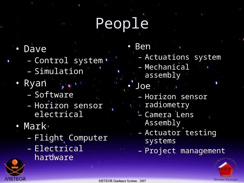
Control System
• Utilize sensor inputs
• Determine response
• Generate commands for actuators

Complementary Filter
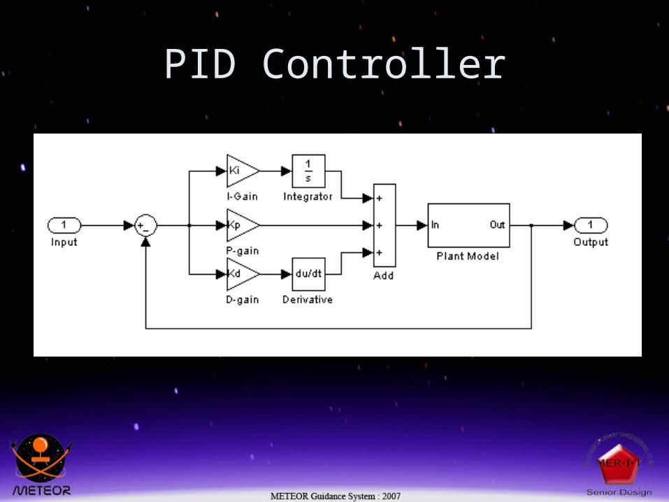
PID Controller

Sensors
• Inertial Measurements Unit– Off the shelf IMU– 3 axis acceleration– 3 axis rotation rate– Digital output 150 Hz
• Horizon Sensor– Custom made– CMOS imaging sensor– Wide angle lens– Band Pass filtered

IMU• Internal ADC with temperature
compensation• RS-422 Digital Output• 5G Accelerometers on all three
axis• 300 Deg/s Rate Gyros on all three
axis• 35G Accelerometers on two axis• Non Idealities
-Acceleration dependant Gyro bias

Horizon Sensor
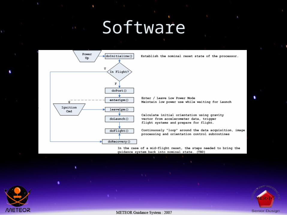
Software

Image processing
Equidistant point algorithm-Removes curvature of earth-Simple orientation extraction
Pixel luminosity thresholding-Easy to implement-Uses constant threshold value-Can use a variable threshold lookup table vs altitude

Flight Computer
• Custom design• TI 2808 DSP• 4 layer PCB• SMT construction
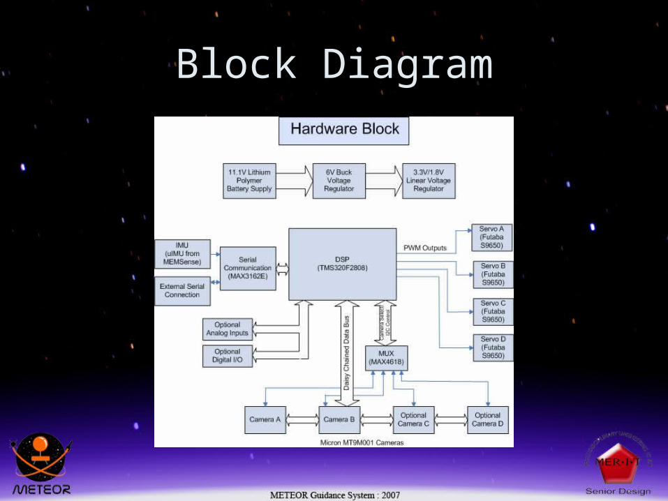
Block Diagram
Actuators
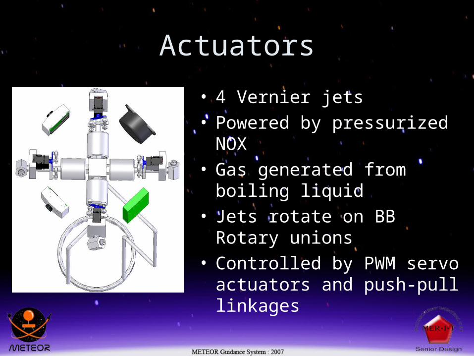
• 4 Vernier jets• Powered by pressurized NOX• Gas generated from boiling
liquid• Jets rotate on BB Rotary
unions• Controlled by PWM servo
actuators and push-pull linkages
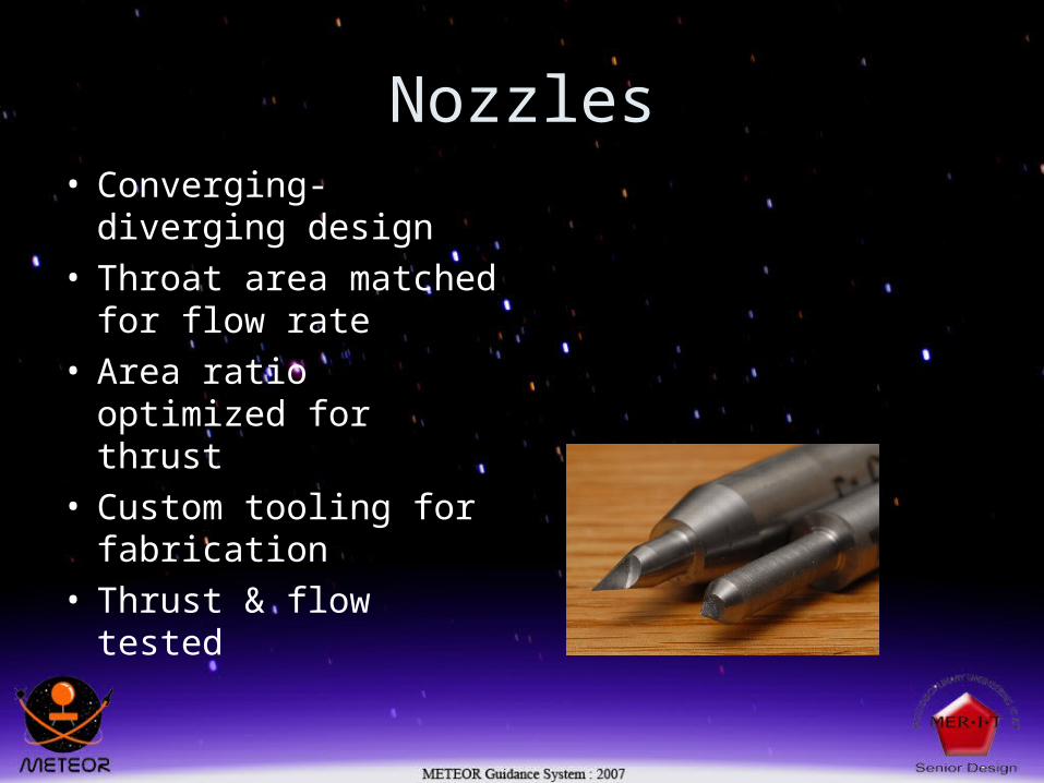
Nozzles• Converging-diverging
design• Throat area matched
for flow rate• Area ratio optimized
for thrust• Custom tooling for
fabrication• Thrust & flow tested
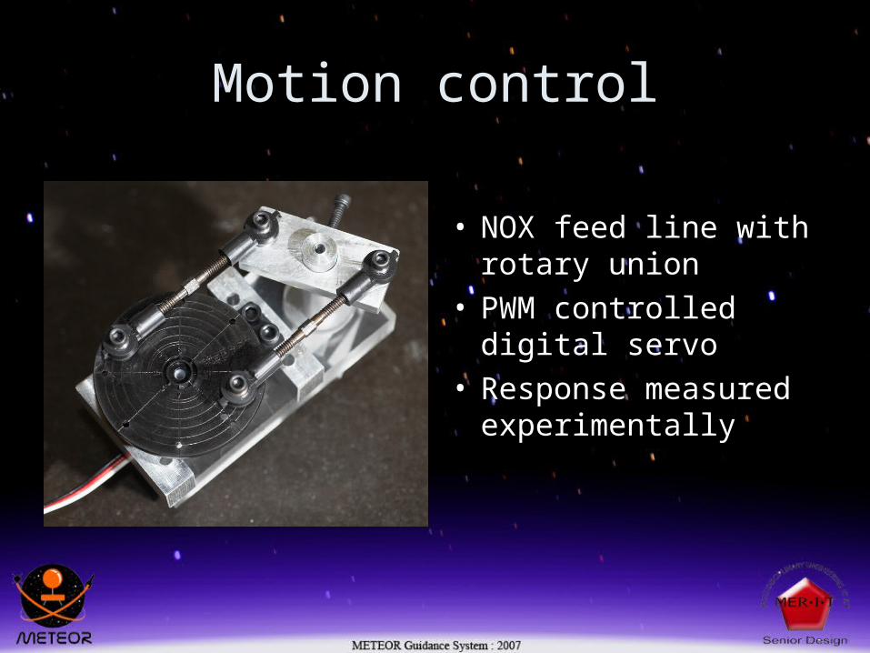
Motion control
• NOX feed line with rotary union
• PWM controlled digital servo
• Response measured experimentally
Simulation
• 2D simulations– Spec thruster output– Spec mass and burn time to other groups– Determine worst case trajectory
• 3D simulations– Test control system– Test actuator response– Spec thrust axis tolerances
2D simulations
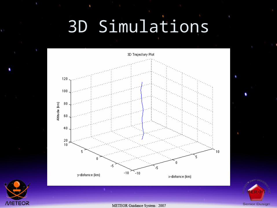
3D Simulations
Conclusions
• Micron CMOS sensors not performing as indicated in spec sheet
• Horizon sensors n