MECHANICS OF MATERIALS - 生醫工程分析實驗室€¦ · · 2016-03-01MECHANICS OF MATERIALS...
39
MECHANICS OF MATERIALS Ferdinand P. Beer E. Russell Johnston, Jr. John T. DeWolf David F. Mazurek Lecture Notes: J. Walt Oler Texas Tech University CHAPTER 2 Stress and Strain – Axial Loading
Transcript of MECHANICS OF MATERIALS - 生醫工程分析實驗室€¦ · · 2016-03-01MECHANICS OF MATERIALS...
MECHANICS OF
MATERIALSFerdinand P. Beer
E. Russell Johnston, Jr.
John T. DeWolf
David F. Mazurek
Lecture Notes:
J. Walt Oler
Texas Tech University
CHAPTER
2Stress and
Strain – Axial
Loading
MECHANICS OF MATERIALS Beer • Johnston • DeWolf • Mazurek
2- 2
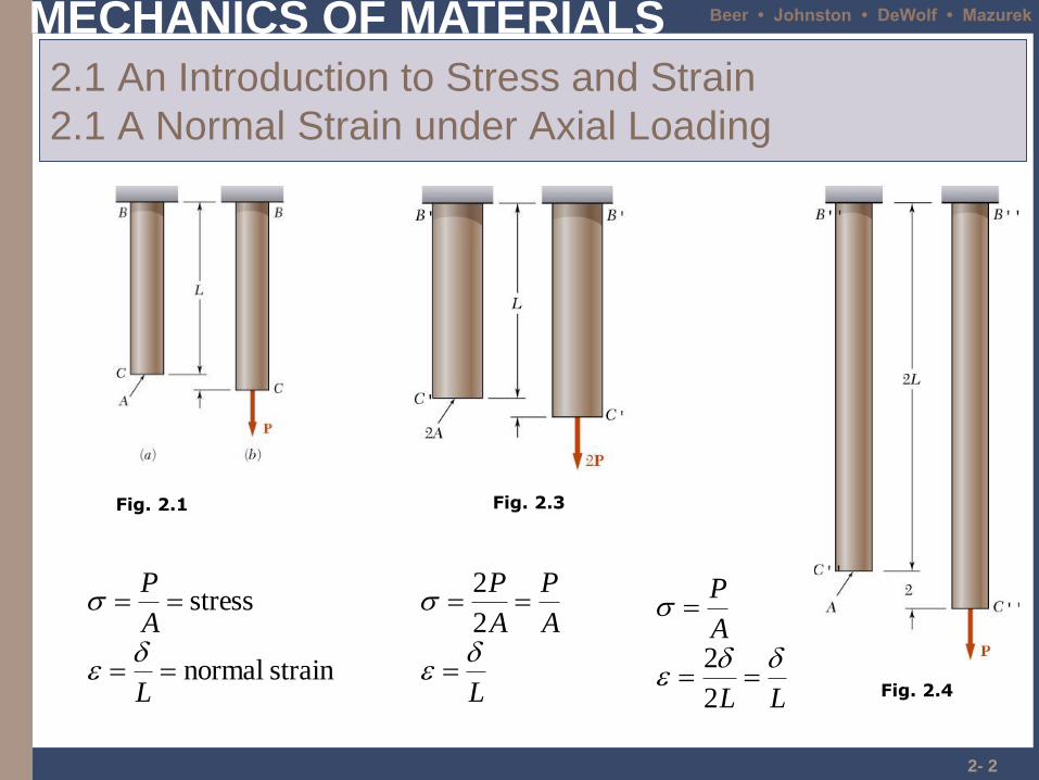
2.1 An Introduction to Stress and Strain
2.1 A Normal Strain under Axial Loading
strain normal
stress
L
A
P
Fig. 2.1
L
A
P
A
P
2
2
Fig. 2.3
LL
A
P
2
2Fig. 2.4
MECHANICS OF MATERIALS Beer • Johnston • DeWolf • Mazurek
2- 3
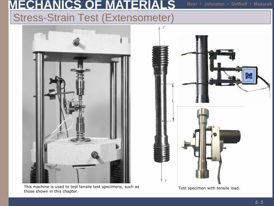
Stress-Strain Test (Extensometer)
This machine is used to test tensile test specimens, such as those shown in this chapter.
Test specimen with tensile load.
MECHANICS OF MATERIALS Beer • Johnston • DeWolf • Mazurek
MECHANICS OF MATERIALS Beer • Johnston • DeWolf • Mazurek
2- 5
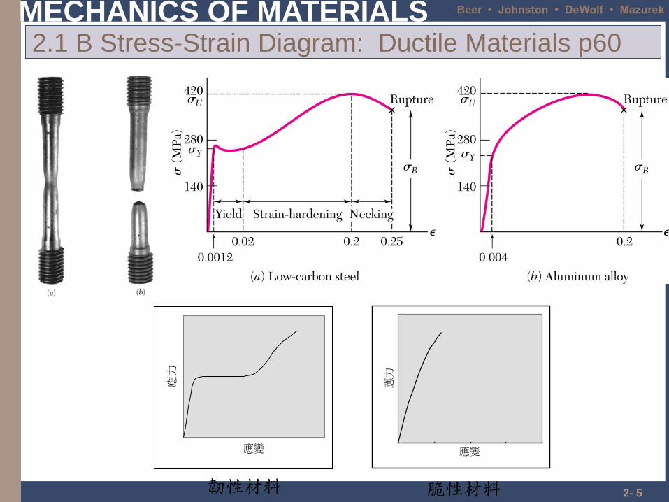
2.1 B Stress-Strain Diagram: Ductile Materials p60
應變
應力
韌性材料
應變
應力
脆性材料
MECHANICS OF MATERIALS Beer • Johnston • DeWolf • Mazurek
2- 6
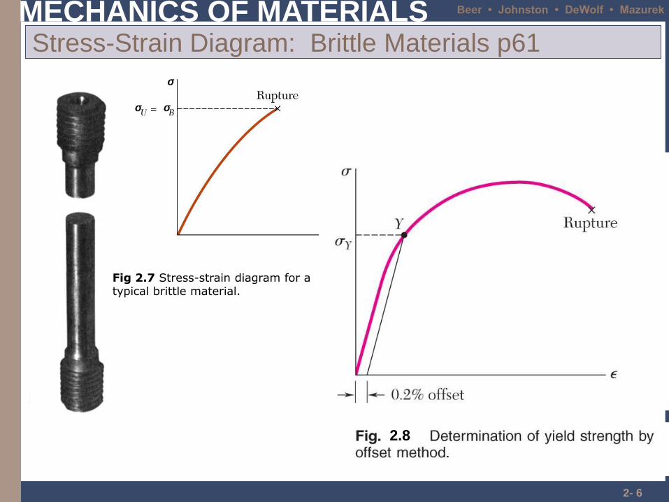
Stress-Strain Diagram: Brittle Materials p61
Fig 2.7 Stress-strain diagram for a typical brittle material.
2.8
MECHANICS OF MATERIALS Beer • Johnston • DeWolf • Mazurek
2- 7
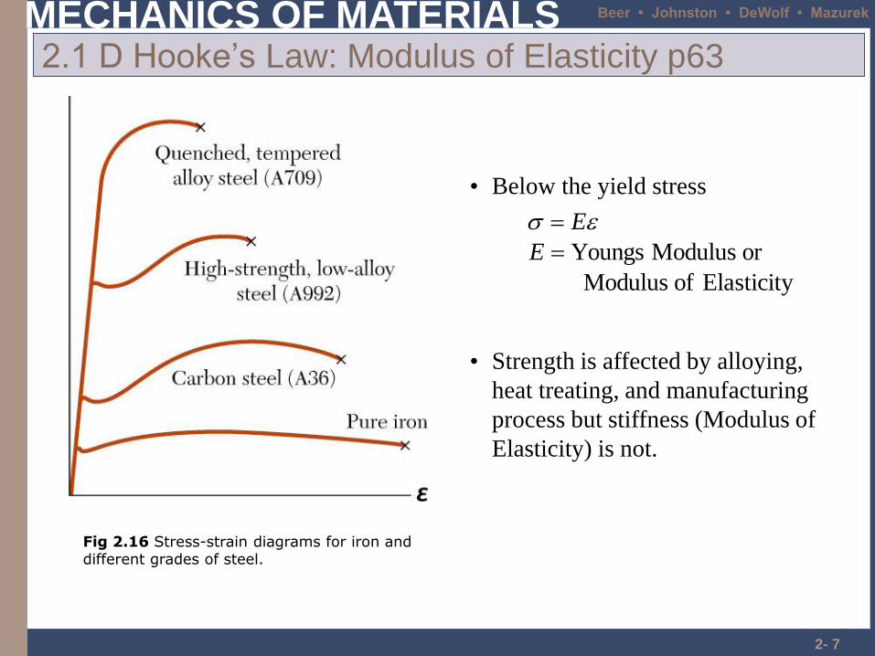
2.1 D Hooke’s Law: Modulus of Elasticity p63
• Below the yield stress
Elasticity of Modulus
or Modulus Youngs
E
E
• Strength is affected by alloying,
heat treating, and manufacturing
process but stiffness (Modulus of
Elasticity) is not.
Fig 2.16 Stress-strain diagrams for iron and different grades of steel.
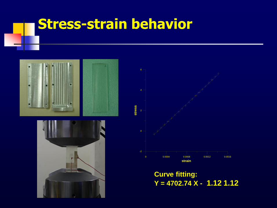
0 0.0004 0.0008 0.0012 0.0016
strain
-2
0
2
4
6
str
ess
Curve fitting:
Y = 4702.74 X - 1.12 1.12
Stress-strain behavior
MECHANICS OF MATERIALS Beer • Johnston • DeWolf • Mazurek
2- 9
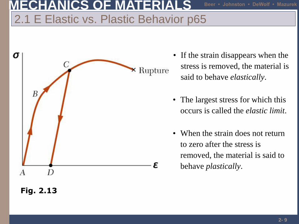
2.1 E Elastic vs. Plastic Behavior p65
• If the strain disappears when the
stress is removed, the material is
said to behave elastically.
• When the strain does not return
to zero after the stress is
removed, the material is said to
behave plastically.
• The largest stress for which this
occurs is called the elastic limit.
Fig. 2.13
MECHANICS OF MATERIALS Beer • Johnston • DeWolf • Mazurek
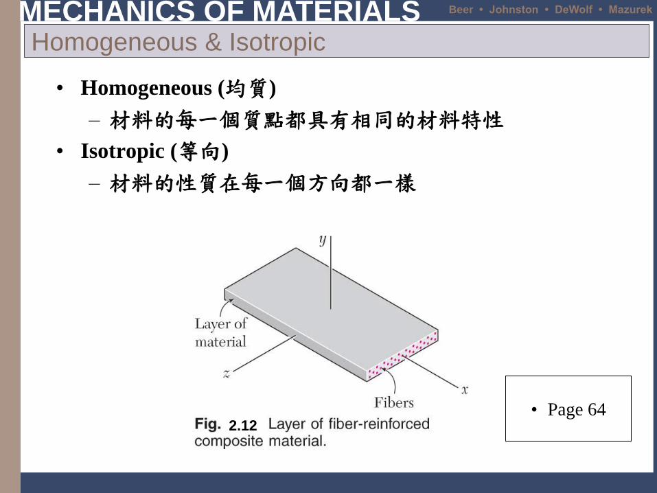
• Homogeneous (均質)
– 材料的每一個質點都具有相同的材料特性
• Isotropic (等向)
– 材料的性質在每一個方向都一樣
Homogeneous & Isotropic
• Page 642.12
MECHANICS OF MATERIALS Beer • Johnston • DeWolf • Mazurek
2- 11
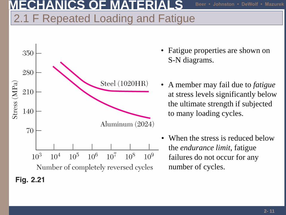
2.1 F Repeated Loading and Fatigue
• Fatigue properties are shown on
S-N diagrams.
• When the stress is reduced below
the endurance limit, fatigue
failures do not occur for any
number of cycles.
• A member may fail due to fatigue
at stress levels significantly below
the ultimate strength if subjected
to many loading cycles.
MECHANICS OF MATERIALS Beer • Johnston • DeWolf • Mazurek
2- 12
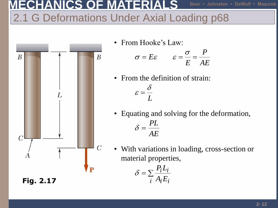
2.1 G Deformations Under Axial Loading p68
AE
P
EE
• From Hooke’s Law:
• From the definition of strain:
L
• Equating and solving for the deformation,
AE
PL
• With variations in loading, cross-section or
material properties,
i ii
ii
EA
LP
Fig. 2.17
MECHANICS OF MATERIALS Beer • Johnston • DeWolf • Mazurek
2- 13
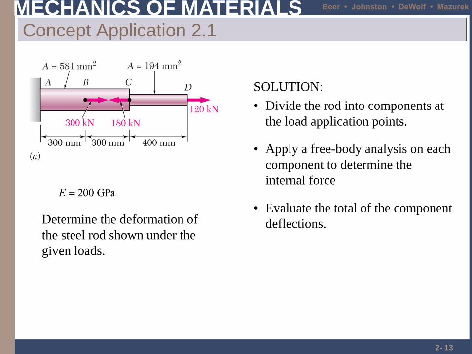
Concept Application 2.1
Determine the deformation of
the steel rod shown under the
given loads.
SOLUTION:
• Divide the rod into components at
the load application points.
• Apply a free-body analysis on each
component to determine the
internal force
• Evaluate the total of the component
deflections.
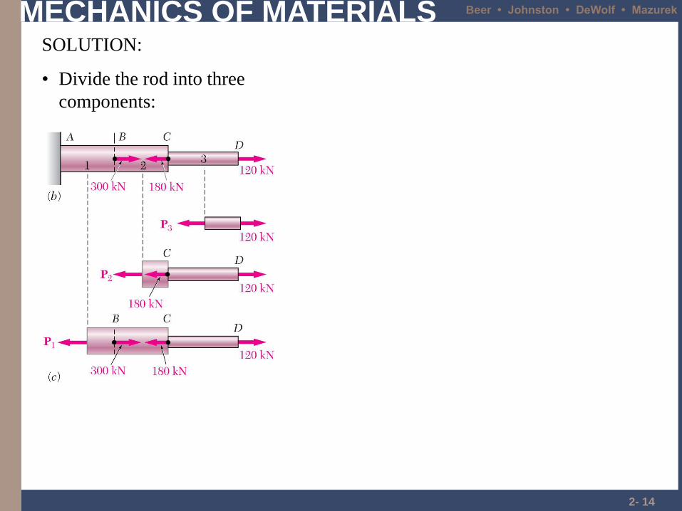
MECHANICS OF MATERIALS Beer • Johnston • DeWolf • Mazurek
2- 14
SOLUTION:
• Divide the rod into three
components:
MECHANICS OF MATERIALS Beer • Johnston • DeWolf • Mazurek
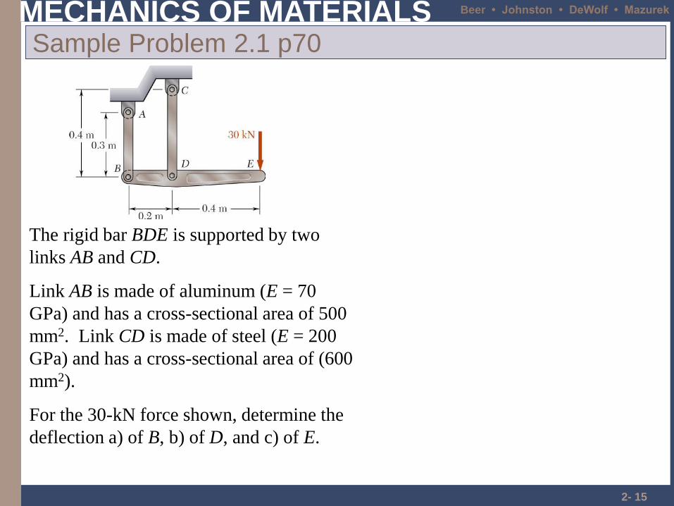
2- 15
Sample Problem 2.1 p70
The rigid bar BDE is supported by two
links AB and CD.
Link AB is made of aluminum (E = 70
GPa) and has a cross-sectional area of 500
mm2. Link CD is made of steel (E = 200
GPa) and has a cross-sectional area of (600
mm2).
For the 30-kN force shown, determine the
deflection a) of B, b) of D, and c) of E.
MECHANICS OF MATERIALS Beer • Johnston • DeWolf • Mazurek
2- 16
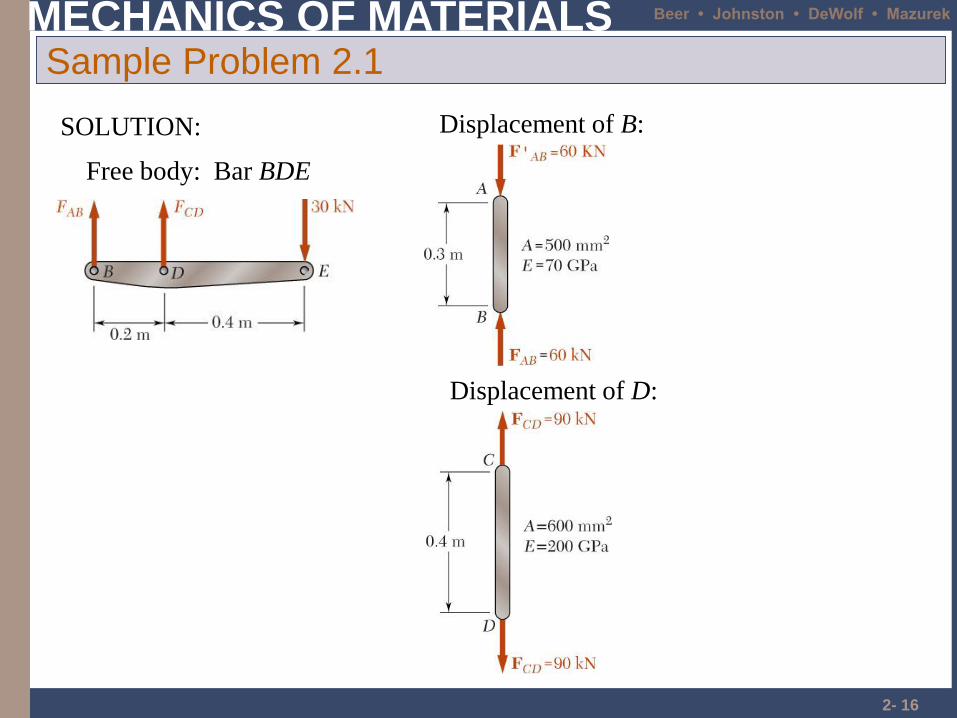
Sample Problem 2.1
Free body: Bar BDE
SOLUTION: Displacement of B:
Displacement of D:
MECHANICS OF MATERIALS Beer • Johnston • DeWolf • Mazurek
2- 17
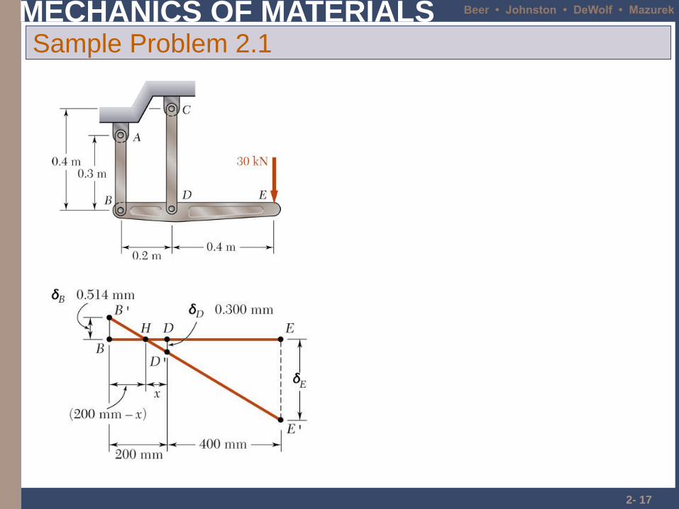
Sample Problem 2.1
MECHANICS OF MATERIALS Beer • Johnston • DeWolf • Mazurek
Problems
• Page 71 Sample problem 2.2
• Page 77 2.26, 2.27
MECHANICS OF MATERIALS Beer • Johnston • DeWolf • Mazurek
2- 19
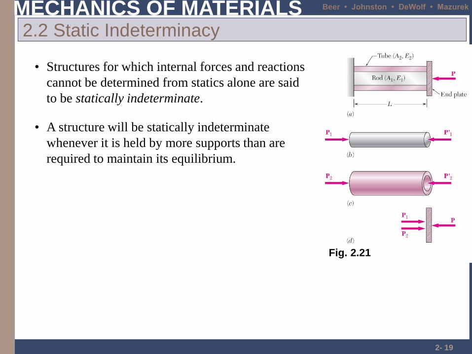
2.2 Static Indeterminacy
• Structures for which internal forces and reactions
cannot be determined from statics alone are said
to be statically indeterminate.
• A structure will be statically indeterminate
whenever it is held by more supports than are
required to maintain its equilibrium.
Fig. 2.21
MECHANICS OF MATERIALS Beer • Johnston • DeWolf • Mazurek
2- 20
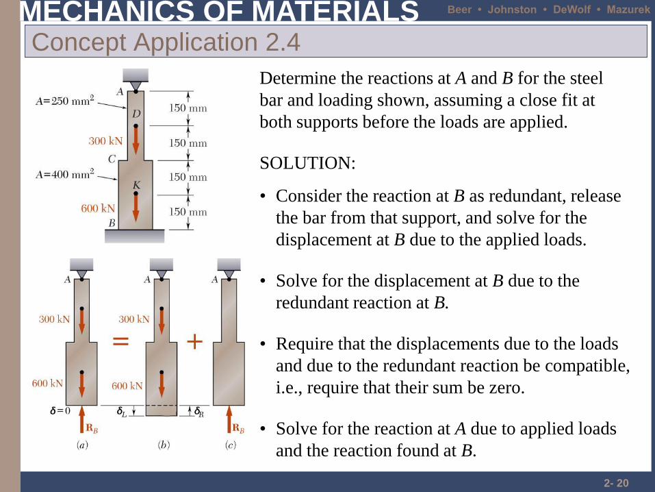
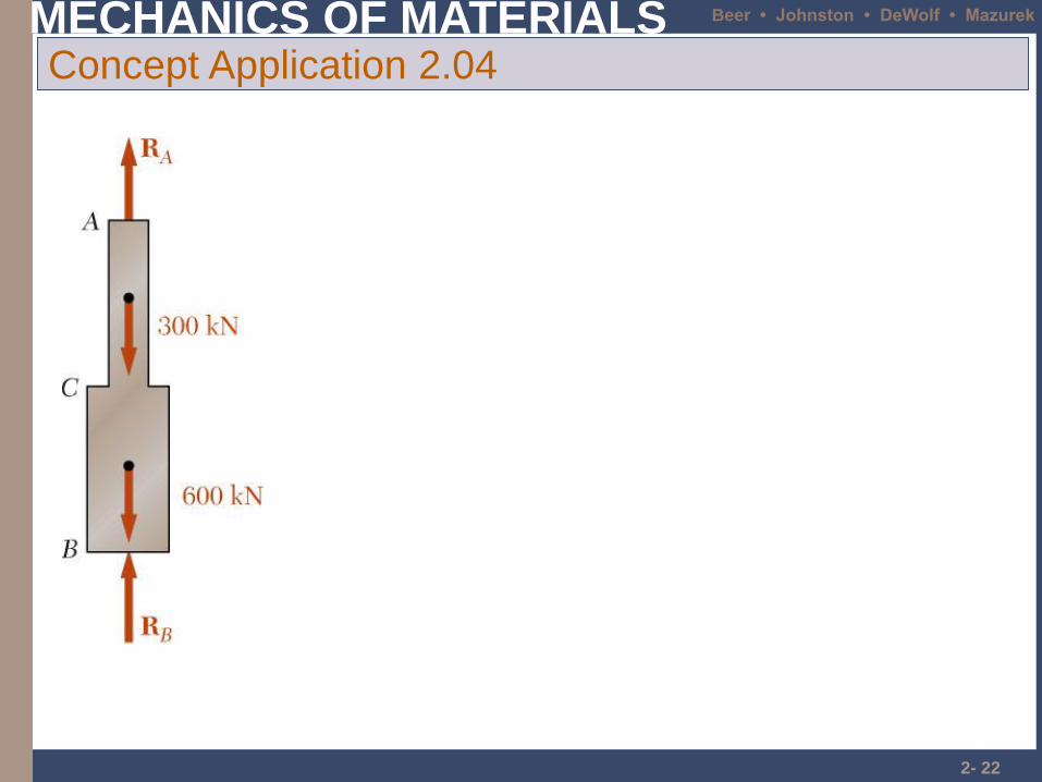
Concept Application 2.4
Determine the reactions at A and B for the steel
bar and loading shown, assuming a close fit at
both supports before the loads are applied.
• Solve for the reaction at A due to applied loads
and the reaction found at B.
• Require that the displacements due to the loads
and due to the redundant reaction be compatible,
i.e., require that their sum be zero.
• Solve for the displacement at B due to the
redundant reaction at B.
SOLUTION:
• Consider the reaction at B as redundant, release
the bar from that support, and solve for the
displacement at B due to the applied loads.
MECHANICS OF MATERIALS Beer • Johnston • DeWolf • Mazurek
2- 21
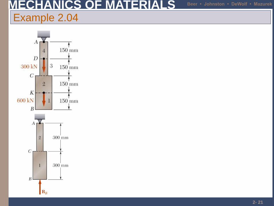
Example 2.04
MECHANICS OF MATERIALS Beer • Johnston • DeWolf • Mazurek
2- 22
Concept Application 2.04
MECHANICS OF MATERIALS Beer • Johnston • DeWolf • Mazurek
2- 23
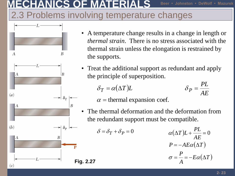
2.3 Problems involving temperature changes
• A temperature change results in a change in length or
thermal strain. There is no stress associated with the
thermal strain unless the elongation is restrained by
the supports.
coef.expansion thermal
AE
PLLT PT
• Treat the additional support as redundant and apply
the principle of superposition.
0 PT
• The thermal deformation and the deformation from
the redundant support must be compatible.
TEA
P
TAEP
AE
PLLT
0
Fig. 2.27
MECHANICS OF MATERIALS Beer • Johnston • DeWolf • Mazurek
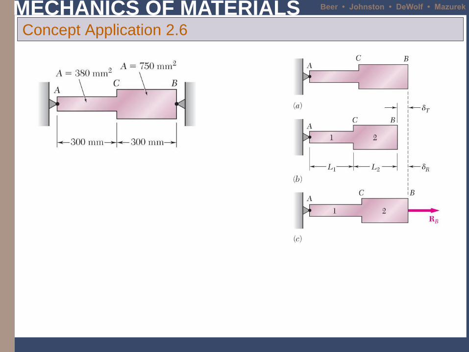
Concept Application 2.6

MECHANICS OF MATERIALS Beer • Johnston • DeWolf • Mazurek
Concept Application 2.6
MECHANICS OF MATERIALS Beer • Johnston • DeWolf • Mazurek
Problems
• Page 86 Sample problem 2.3
• Page 87 Sample problem 2.4
MECHANICS OF MATERIALS Beer • Johnston • DeWolf • Mazurek
2- 27
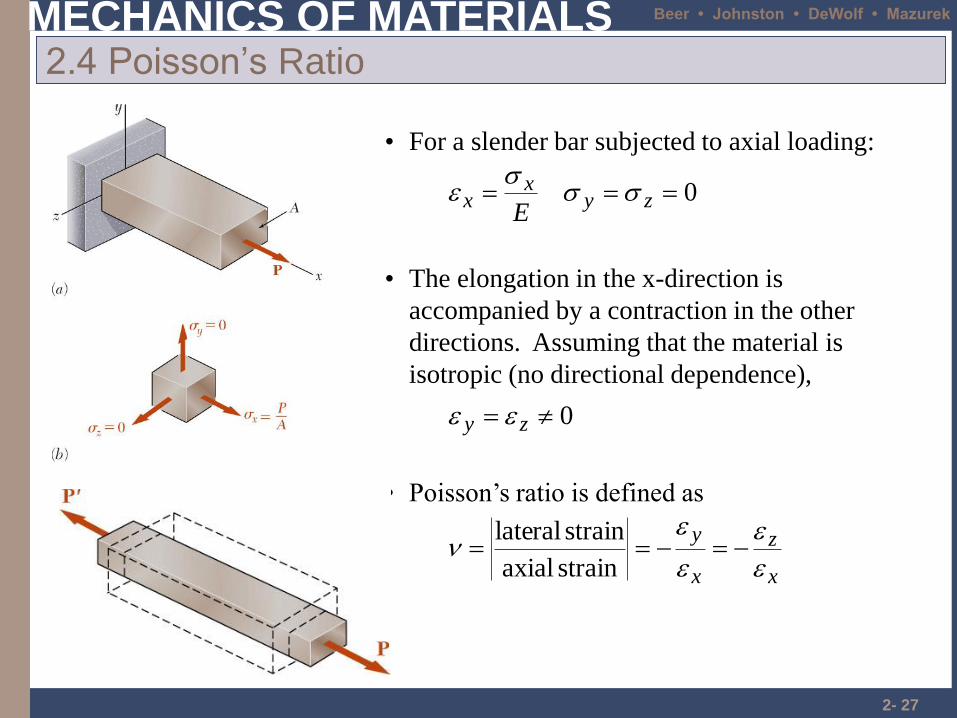
2.4 Poisson’s Ratio
• For a slender bar subjected to axial loading:
0 zyx
xE
• The elongation in the x-direction is
accompanied by a contraction in the other
directions. Assuming that the material is
isotropic (no directional dependence),
0 zy
• Poisson’s ratio is defined as
x
z
x
y
strain axial
strain lateral
MECHANICS OF MATERIALS Beer • Johnston • DeWolf • Mazurek
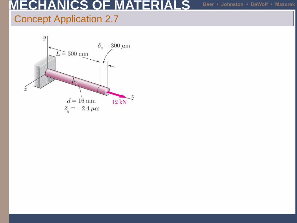
Concept Application 2.7
MECHANICS OF MATERIALS Beer • Johnston • DeWolf • Mazurek
2- 29
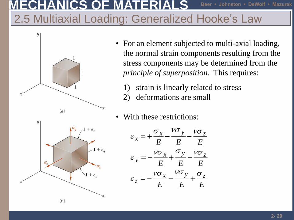
2.5 Multiaxial Loading: Generalized Hooke’s Law
• For an element subjected to multi-axial loading,
the normal strain components resulting from the
stress components may be determined from the
principle of superposition. This requires:
1) strain is linearly related to stress
2) deformations are small
EEE
EEE
EEE
zyxz
zyxy
zyxx
• With these restrictions:
MECHANICS OF MATERIALS Beer • Johnston • DeWolf • Mazurek
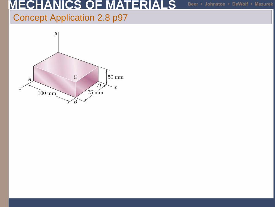
Concept Application 2.8 p97
MECHANICS OF MATERIALS Beer • Johnston • DeWolf • Mazurek
2- 31
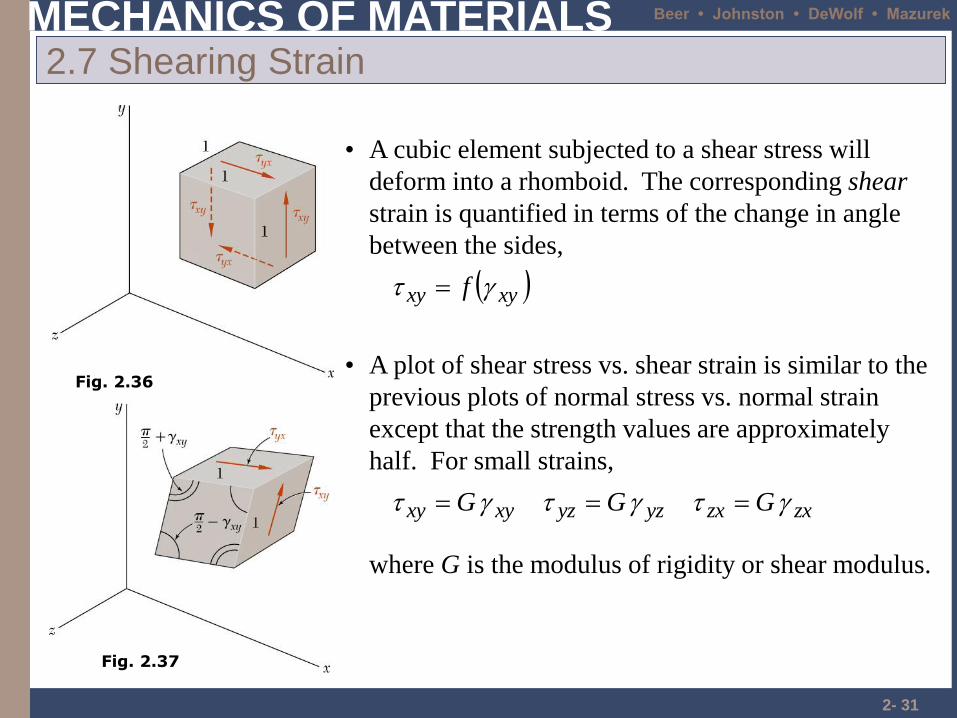
2.7 Shearing Strain
• A cubic element subjected to a shear stress will
deform into a rhomboid. The corresponding shear
strain is quantified in terms of the change in angle
between the sides,
xyxy f
• A plot of shear stress vs. shear strain is similar to the
previous plots of normal stress vs. normal strain
except that the strength values are approximately
half. For small strains,
zxzxyzyzxyxy GGG
where G is the modulus of rigidity or shear modulus.
Fig. 2.36
Fig. 2.37
MECHANICS OF MATERIALS Beer • Johnston • DeWolf • Mazurek
2- 32
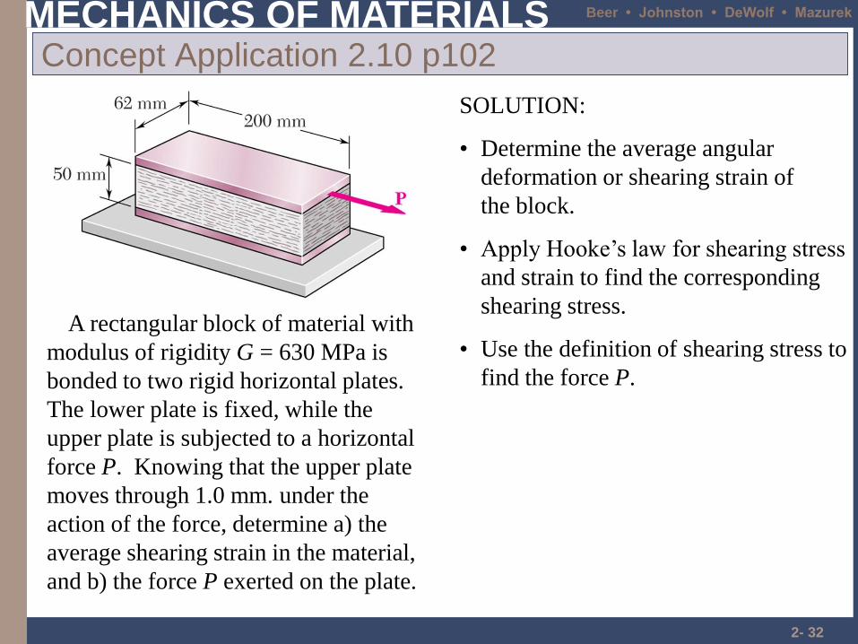
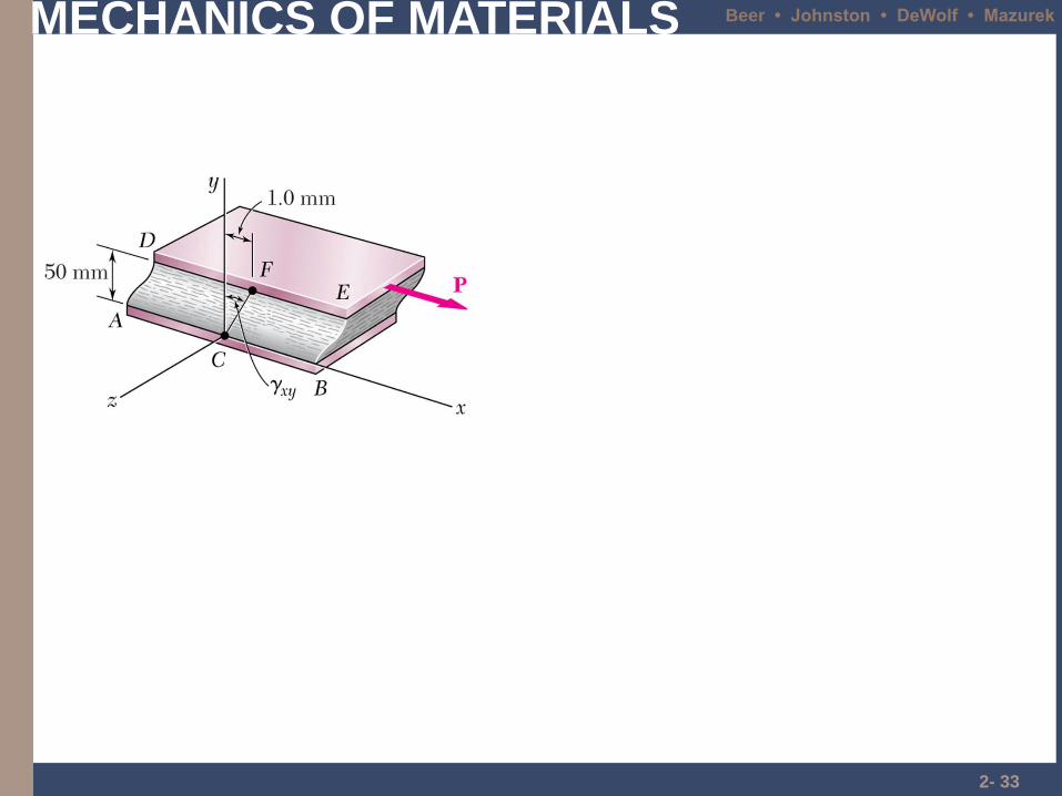
Concept Application 2.10 p102
A rectangular block of material with
modulus of rigidity G = 630 MPa is
bonded to two rigid horizontal plates.
The lower plate is fixed, while the
upper plate is subjected to a horizontal
force P. Knowing that the upper plate
moves through 1.0 mm. under the
action of the force, determine a) the
average shearing strain in the material,
and b) the force P exerted on the plate.
SOLUTION:
• Determine the average angular
deformation or shearing strain of
the block.
• Use the definition of shearing stress to
find the force P.
• Apply Hooke’s law for shearing stress
and strain to find the corresponding
shearing stress.
MECHANICS OF MATERIALS Beer • Johnston • DeWolf • Mazurek
2- 33
MECHANICS OF MATERIALS Beer • Johnston • DeWolf • Mazurek
2- 34
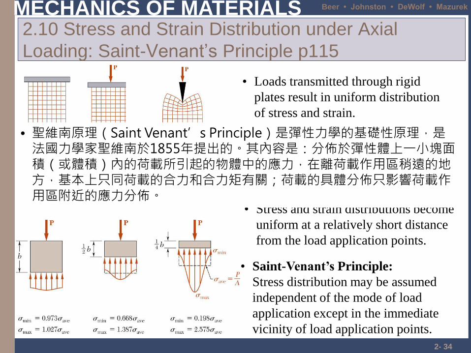
2.10 Stress and Strain Distribution under Axial
Loading: Saint-Venant’s Principle p115
• Loads transmitted through rigid
plates result in uniform distribution
of stress and strain.
• Saint-Venant’s Principle:
Stress distribution may be assumed
independent of the mode of load
application except in the immediate
vicinity of load application points.
• Stress and strain distributions become
uniform at a relatively short distance
from the load application points.
• Concentrated loads result in large
stresses in the vicinity of the load
application point.
• 聖維南原理(Saint Venant’s Principle)是彈性力學的基礎性原理,是法國力學家聖維南於1855年提出的。其內容是:分佈於彈性體上一小塊面積(或體積)內的荷載所引起的物體中的應力,在離荷載作用區稍遠的地方,基本上只同荷載的合力和合力矩有關;荷載的具體分佈只影響荷載作用區附近的應力分佈。
MECHANICS OF MATERIALS Beer • Johnston • DeWolf • Mazurek
2- 35
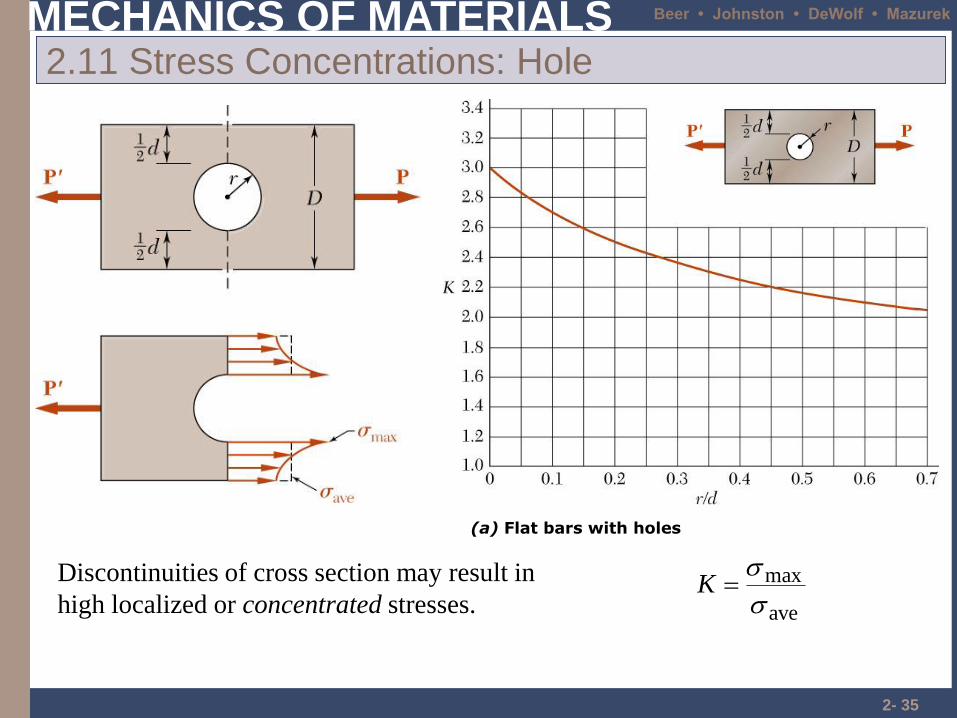
2.11 Stress Concentrations: Hole
Discontinuities of cross section may result in
high localized or concentrated stresses. ave
max
K
(a) Flat bars with holes
MECHANICS OF MATERIALS Beer • Johnston • DeWolf • Mazurek
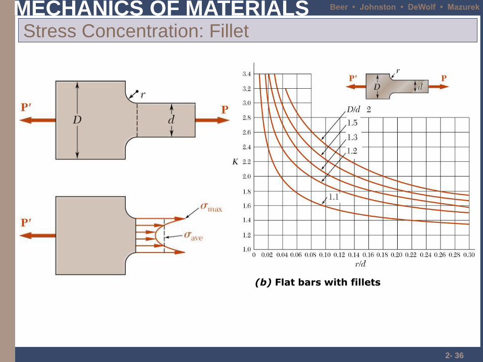
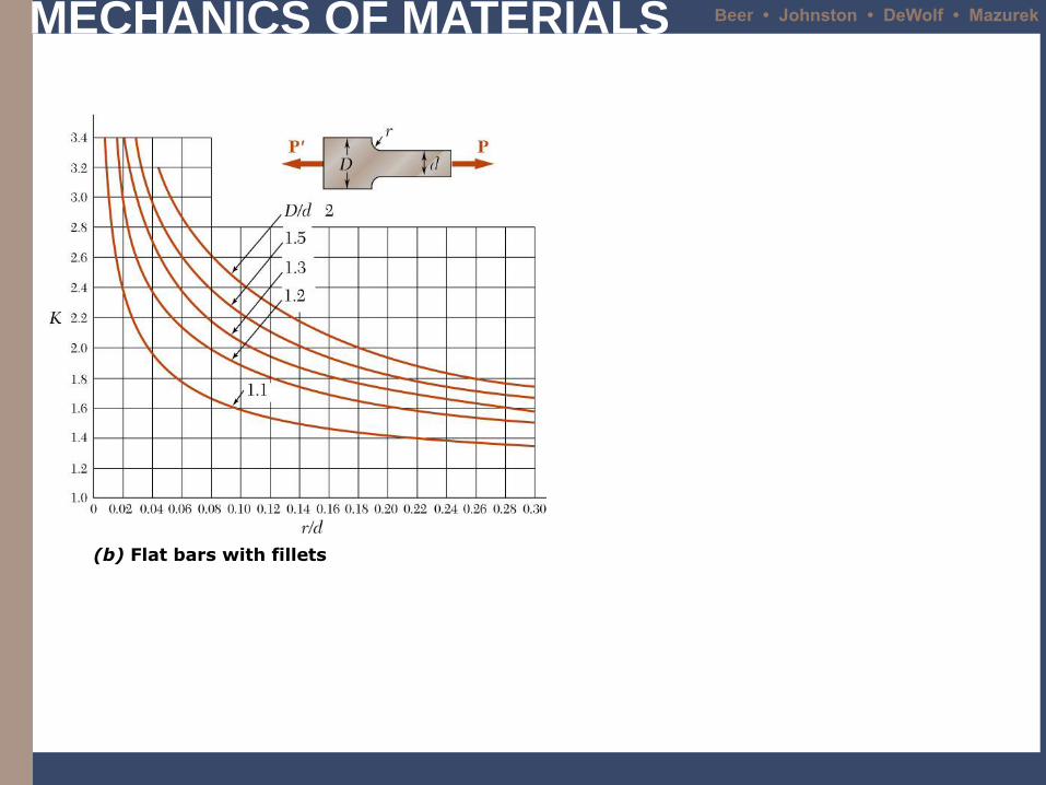
2- 36
Stress Concentration: Fillet
(b) Flat bars with fillets
MECHANICS OF MATERIALS Beer • Johnston • DeWolf • Mazurek
2- 37
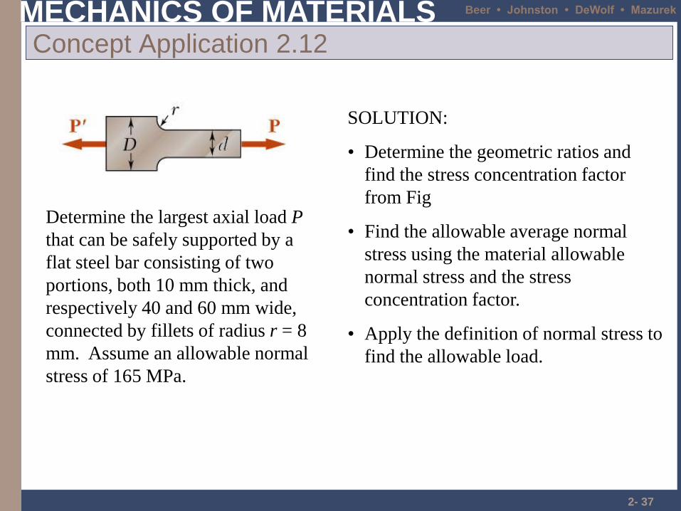
Concept Application 2.12
Determine the largest axial load P
that can be safely supported by a
flat steel bar consisting of two
portions, both 10 mm thick, and
respectively 40 and 60 mm wide,
connected by fillets of radius r = 8
mm. Assume an allowable normal
stress of 165 MPa.
SOLUTION:
• Determine the geometric ratios and
find the stress concentration factor
from Fig
• Apply the definition of normal stress to
find the allowable load.
• Find the allowable average normal
stress using the material allowable
normal stress and the stress
concentration factor.
MECHANICS OF MATERIALS Beer • Johnston • DeWolf • Mazurek
(b) Flat bars with fillets
MECHANICS OF MATERIALS Beer • Johnston • DeWolf • Mazurek
Problems
• Page 131 2.113
• Page 141 2.127