
MCU Test Extension · 1350 ohm copper pair, regardless of the length of the DLC system. Simple to...
4
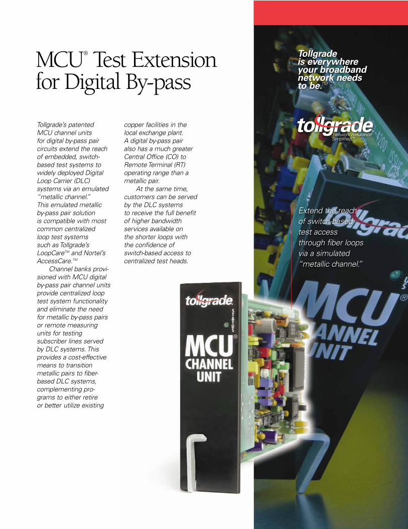
MCU ® Test Extension for Digital By-pass Tollgrade’s patented MCU channel units for digital by-pass pair circuits extend the reach of embedded, switch- based test systems to widely deployed Digital Loop Carrier (DLC) systems via an emulated “metallic channel.” This emulated metallic by-pass pair solution is compatible with most common centralized loop test systems such as Tollgrade’s LoopCare TM and Nortel’s AccessCare. TM Channel banks provi- sioned with MCU digital by-pass pair channel units provide centralized loop test system functionality and eliminate the need for metallic by-pass pairs or remote measuring units for testing subscriber lines served by DLC systems. This provides a cost-effective means to transition metallic pairs to fiber- based DLC systems, complementing pro- grams to either retire or better utilize existing copper facilities in the local exchange plant. A digital by-pass pair also has a much greater Central Office (CO) to Remote Terminal (RT) operating range than a metallic pair. At the same time, customers can be served by the DLC systems to receive the full benefit of higher bandwidth services available on the shorter loops with the confidence of switch-based access to centralized test heads. Extend the reach of switch-based test access through fiber loops via a simulated “metallic channel.” Tollgrade is everywhere your broadband network needs to be. TM
Transcript of MCU Test Extension · 1350 ohm copper pair, regardless of the length of the DLC system. Simple to...
MCU® Test Extensionfor Digital By-pass
Tollgrade’s patentedMCU channel units for digital by-pass pair circuits extend the reachof embedded, switch-based test systems towidely deployed DigitalLoop Carrier (DLC) systems via an emulated“metallic channel.” This emulated metallicby-pass pair solution is compatible with mostcommon centralized loop test systems such as Tollgrade’sLoopCareTM and Nortel’sAccessCare.TM
Channel banks provi-sioned with MCU digitalby-pass pair channel unitsprovide centralized looptest system functionalityand eliminate the needfor metallic by-pass pairsor remote measuringunits for testing subscriber lines servedby DLC systems. Thisprovides a cost-effectivemeans to transitionmetallic pairs to fiber-based DLC systems,complementing pro-grams to either retire or better utilize existing
copper facilities in thelocal exchange plant. A digital by-pass pair also has a much greaterCentral Office (CO) toRemote Terminal (RT)operating range than ametallic pair.
At the same time,customers can be servedby the DLC systems to receive the full benefitof higher bandwidthservices available on the shorter loops withthe confidence of switch-based access to centralized test heads.
Extend the reach of switch-based test access through fiber loopsvia a simulated “metallic channel.”
Tollgrade is everywhere your broadband network needs to be.TM

Primary Features of the MCU Test Extension Solution
Extended Test Capability MCU digital by-pass pairtechnology permits cen-tralized loop test systems(like Tollgrade’s DigiTest®
Measurement Nodes) to perform a full range oftests with the speed andaccuracy of a high qualitymetallic by-pass pair,while not subject toinductive interference,ground potential prob-lems or other environ-mental conditions. Inaddition, a DLC channelprovisioned with MCU digital by-pass pair chan-nel units emulates a1350 ohm copper pair,regardless of the lengthof the DLC system.
Simple to UseThe MCU digital by-passpair channel units allowfor immediate test capability via telephonenumber, as no specialdatabase changes arerequired. An MCU chan-nel unit contains a num-ber of user-selectableoptions, depending on the requirements of the DLC system inwhich it is installed. Only three leads at theCO and two leads at theRT are required to becross-connected. AnMCU digital by-pass pairchannel unit occupies asingle physical slot in theCO terminal and RT.
Depending on the DLCsystem, the MCU chan-nel unit may be installedin any available slot.
CompatibilityAn MCU digital by-passpair channel unit is available for the mostcommonly deployed DLC and D4-compatiblechannel banks, providingfor a uniform testingsolution across sub-scriber loop deployments.Furthermore, every MCUchannel unit is end-to-end compatible with all other licensed or manufactured MCUchannel units designedfor the digital by-pass pairapplication.
The following architectures depict typical configurations illustrating how MCU channel units may be deployed to create a digital by-pass pair.
Typical Universal DLC Configuration
RTNTT
PGTC
CLASS 5
CENTRAL OFFICE
COT
CTU DIGITESTMEASUREMENT
NODES
MCUCHANNEL
UNIT
MCUCHANNEL
UNIT
In Universal DLC applications, MCU channel units are inserted in both the COT and RT to provide a digital by-pass pair to emulate the metallic by-pass pair.
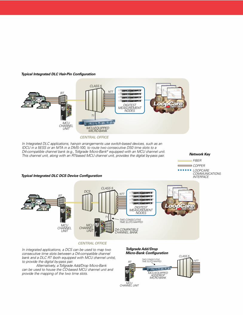
Typical Integrated DLC Hair-Pin Configuration
In Integrated DLC applications, hair-pin arrangements use switch-based devices, such as anIDCU in a 5ESS or an MTA in a DMS-100, to route two consecutive DS0 time slots to a D4-compatible channel bank (e.g., Tollgrade Micro-Bank® equipped with an MCU channel unit.This channel unit, along with an RT-based MCU channel unit, provides the digital by-pass pair.
Typical Integrated DLC DCS Device Configuration
In integrated applications, a DCS can be used to map twoconsecutive time slots between a D4-compatible channelbank and a DLC RT (both equipped with MCU channel units),to provide the digital by-pass pair.
Alternatively, a Tollgrade Add/Drop Micro-Bank can be used to house the CO-based MCU channel unit andprovide the mapping of the two time slots.
MCU-EQUIPPEDMICRO-BANK
CLASS 5
MCUCHANNEL
UNIT
CENTRAL OFFICE
RT NTT
T1
DIGITESTMEASUREMENT
NODES
MCUCHANNEL
UNIT
RT
CLASS 5
CENTRAL OFFICE
NTT
T1TWO CONSECUTIVETIME SLOTS MAPPED
DIGITESTMEASUREMENT
NODES
MCUCHANNEL
UNIT D4-COMPATIBLECHANNEL BANK
DCS
MCUCHANNEL UNIT
RT
MCU-EQUIPPEDADD/DROP
MICRO-BANK
TWO CONSECUTIVETIME SLOTS MAPPED
CLASS 5
NTT
Tollgrade Add/Drop Micro-Bank Configuration
FIBER
COPPERLOOPCARECOMMUNICATIONSINTERFACE
Network Key

Corporate Headquarters493 Nixon RoadCheswick, PA 15024
Other Locations:Bridgewater, NJSarasota, FL
1-800-878-3399
www.tollgrade.comOrdering Information
Product (System Compatibility) Part Number CLEI/HECIMCU-5405, List 4 TLGD-5405-L4 5SC26T02AE(Lucent SLC® Series 5, SLC-2000 and AnyMedia®)
MCU-4496ER, List 5 TLGD-4496ER-L5 S9CS678BAE(Lucent SLC 96 and D4®-Compatible Channel Banks)
MCU-A405 (Adtran TA 1500) TLGD-A405 VAI1SK0CAB
MCU-D405, List 2 TLGD-D405-L2 SLCIDED2AB(Alcatel Litespan® 2000/2012)
MCU-F405, List 3 (Fujitsu FDLC) TLGD-F405-L3 5SC3FG03AC
MCU-N405, List 2 (Zhone ISC-303) TLGD-N405-L2 5SC26508AB
MCU-R405, Issue 2, List 2 TLGD-SCU26A-I2-L2 SLCIDEG2AB(Tellabs DISC*S®)
AFC now Tellabs DBP Card Contact Tellabs at 707-794-7700(AccessMAXTM)
Calix ADP Card (C7) (GA Q106) Contact Calix at 877-766-3500
Motorola DBP Card (Wireline FTTN USAM and BDT) Contact Motorola at 707-584-6820
Zhone MAC/ITBP Card Contact Zhone at 877-946-6320(AccessNodeTM UE9000)
Zhone ITU/ITBP Card Contact Zhone at 877-946-6320(AccessNode Express)
SpecificationsSpecifications of MCU channel units may vary slightly based on the DLC system in which they are deployed. Please refer to individual product documentation for exact specifications.
Operating Range in the DC to 200Hz bandDC Resistance (T to T) . . . . . . . . . . . . . . . . . . . . . . . . . . . . . . . . . . . . . . . . . . . 675 ohmsDC Resistance (R to R) . . . . . . . . . . . . . . . . . . . . . . . . . . . . . . . . . . . . . . . . . . . 675 ohmsSignaling Voltage Range . . . . . . . . . . . . . . . . . . . . . . . . . . . . . . . . . . . . . . . . +140/–140 V DC Current Limit . . . . . . . . . . . . . . . . . . . . . . . . . . . . . . . . . . . . . . . . . . . . 110 to 120mAPower RequirementsSystem-dependentVoiceband Parameters Insertion Loss at 1004 Hz . . . . . . . . . . . . . . . . . . . . . . . . . . . . . . . . . . . . . . . 5.5+/–1.0dbFrequency Response vs. 1 Khz (504 to3204 Hz) . . . . . . . . . . . . . . . . . . . . . . . . . +/–1.5dbImpedance/2-wire Drop (terminated) . . . . . . . . . . . . . . . . . . . . . . . . . . . . 900 ohms +2uFIdle Circuit Noise . . . . . . . . . . . . . . . . . . . . . . . . . . . . . . . . . . . . . . . . . . . . . . . <25dBrnCOtherStatus LED(s) are provided for SYNC and BUSY indications.Automatic calibration three minutes after insertion and at subsequent 30-minute intervals.NEBS Level 3 Certified, meeting applicable requirements of GR-1089-CORE and GR-0063-CORE.
® Tollgrade, MCU, DigiTest and Micro-Bank are registered trademarks of Tollgrade Communications, Inc.TM “Network Assurance Simplified,” “Tollgrade is everywhere your broadband network needs to be” and LoopCare aretrademarks of Tollgrade Communications, Inc.All other trademarks are the property of their respective owners.© 2005 Tollgrade Communications, Inc. All rights reserved.Specifications are subject to change without notice.


![The princess and the EPR pair - MITaram/talks/10-spread-princeton.pdfEPR pair. • Teleportation [BBCJPW93] is a method for sending one qubit using two classical bits and one EPR pair.](https://static.fdocument.pub/doc/165x107/60bbd19f845cf921b57233ae/the-princess-and-the-epr-pair-mit-aramtalks10-spread-epr-pair-a-teleportation.jpg)
