
Mathematical Modelling and Pitch Attitude Hold Design for...
18
Bu çalışmanın ilk versiyonu TOK 2015 Kongresinde yayınlanmıştır. Mathematical Modelling and Pitch Attitude Hold Design for a Wing-in-Ground (WIG) Effect Vehicle Abdul Ghafoor 1 , Raha Shabani 2 , Kemal Leblebicioğlu 3 1 Elektrik-Elektronik Mühendisliği Bölümü Middle East Technical University, Ankara [email protected] 2 Elektrik-Elektronik Mühendisliği Bölümü Middle East Technical University, Ankara [email protected] 3 Elektrik-Elektronik Mühendisliği Bölümü Middle East Technical University, Ankara [email protected] Özet “Ground Effect” (GE) (Yer Etkisi) zemine yakınlaştığınızda, zeminin ek bir kaldırma yüzeyi gibi davranmasından dolayı uçağın kaldırma kuvvetindeki artıştır. Zemin etkisi araçları (GEV) bu etkileşimi kullanarak verimliliklerini 3-4 kat artırırlar. Bu çalışmada, önce, zemin etkisinin matematiksel modeli, aerodinamik kuvvetler, yerçekimi, atmosfer etkileri, kitle ataleti kuvvetleri ve momentleri üzerinden elde edilmiştir. Sonuçta ortaya çıkan doğrusal olmayan 6DOF dinamik model, Matlab/Simulink ortamında simüle edilmiştir. Açık çevrim simülasyonlar üzerinden matematiksel modelin doğruluğu araştırılmıştır. Daha sonraki aşamalarda, PID kontrolcüler kullanılarak yunuslama açısı otopilotu tasarımına başlanmıştır. Sonraki aşamalarda yuvarlanma açısı ve hız otopilotlar tasarlanacaktır. Abstract The “ground effect” is the increase in the force which is acting on a lifting surface or wing, when it comes close to the proximity of the ground. Ground effect vehicles (GEV) are the kind of amphibious vehicles that fly in close proximity of ground, making use of the aerodynamic interaction between the wings and the ground (Sea or Earth surface). It increases their efficiency 3-4 times. In this paper mathematical model including Ground Effect (GE), aerodynamics, gravity, atmospheric effects, mass inertia, forces and moments is determined. Nonlinear 6DOF dynamical model is than implemented in Matlab/Simulink and its response was investigated in open loop simulations. In the next step, pitch angle autopilot has been designed by using PID controllers. Roll and speed autopilots will be considered in the future.
Transcript of Mathematical Modelling and Pitch Attitude Hold Design for...
Bu çalışmanın ilk versiyonu TOK 2015 Kongresinde yayınlanmıştır.
Mathematical Modelling and Pitch Attitude Hold Design for a
Wing-in-Ground (WIG) Effect Vehicle
Abdul Ghafoor1, Raha Shabani
2, Kemal Leblebicioğlu
3
1
Elektrik-Elektronik Mühendisliği Bölümü
Middle East Technical University, Ankara [email protected]
2Elektrik-Elektronik Mühendisliği Bölümü
Middle East Technical University, Ankara [email protected]
3Elektrik-Elektronik Mühendisliği Bölümü
Middle East Technical University, Ankara [email protected]
Özet
“Ground Effect” (GE) (Yer Etkisi) zemine yakınlaştığınızda, zeminin ek bir kaldırma yüzeyi gibi
davranmasından dolayı uçağın kaldırma kuvvetindeki artıştır. Zemin etkisi araçları (GEV) bu
etkileşimi kullanarak verimliliklerini 3-4 kat artırırlar. Bu çalışmada, önce, zemin etkisinin
matematiksel modeli, aerodinamik kuvvetler, yerçekimi, atmosfer etkileri, kitle ataleti kuvvetleri
ve momentleri üzerinden elde edilmiştir. Sonuçta ortaya çıkan doğrusal olmayan 6DOF dinamik
model, Matlab/Simulink ortamında simüle edilmiştir. Açık çevrim simülasyonlar üzerinden
matematiksel modelin doğruluğu araştırılmıştır. Daha sonraki aşamalarda, PID kontrolcüler
kullanılarak yunuslama açısı otopilotu tasarımına başlanmıştır. Sonraki aşamalarda yuvarlanma
açısı ve hız otopilotlar tasarlanacaktır.
Abstract
The “ground effect” is the increase in the force which is acting on a lifting surface or wing, when
it comes close to the proximity of the ground. Ground effect vehicles (GEV) are the kind of
amphibious vehicles that fly in close proximity of ground, making use of the aerodynamic
interaction between the wings and the ground (Sea or Earth surface). It increases their efficiency
3-4 times. In this paper mathematical model including Ground Effect (GE), aerodynamics,
gravity, atmospheric effects, mass inertia, forces and moments is determined. Nonlinear 6DOF
dynamical model is than implemented in Matlab/Simulink and its response was investigated in
open loop simulations. In the next step, pitch angle autopilot has been designed by using PID
controllers. Roll and speed autopilots will be considered in the future.
Bu çalışmanın ilk versiyonu TOK 2015 Kongresinde yayınlanmıştır.
1. Introduction
For an aircraft the phenomenon becomes much more appreciable when it is flying near to the sea
(ground or surface earth). The ground plane alters the flow field around the wing, resulting in a
reduction in induced drag and an increase in lift. The so-called WIG craft exploits this behavior
creating a unique class of high-speed, low-altitude transport vehicles. These vehicle are much
more efficient when it comes to payload, speed and cost as compared with other crafts. At the
same time they are user friendly and have a vast scope in civil as well as in military applications.
The ground effect was first investigated seriously around 1920. Wieselsberger (1921) treated the
problem with an extension of the Lanchester Prandtl theory and utilized the basic concept of the
induced drag of multiplanes. Tsiolkovsky (1927) described the ground effect and provided a
theoretical solution for air cushion vehicles
This paper explains studies about ground effect and its advantages in term of improved lift to
drag ratio. Next is its 6 DOF dynamical nonlinear model. This model includes the ground effect
and other phenomenon such as aerodynamics, atmospheric model, gravity, propulsion, mass
inertia model, and different forces and moments. It has been implemented in Matlab/Simulink
and its response to some inputs and disturbances has been observed. Finally an autopilot has
been developed for pitch attitude hold control using PID controllers. In the future, autopilots for
other modes will be studied.
2. Lift, Drag and Ground Effect Theory
As wing moves through air a resultant force is generated
(1)
This resultant force can be decomposed into lift (perpendicular to the free stream velocity) and
induced drag (parallel to the free stream velocity).
(2)
(3)
To handle different wind conditions, non-dimensional representations are used based on the
pressure coefficient:
(4)
is the local static pressure and free-stream (at ∞) static pressure, non-dimensionalized by
the free-stream dynamic pressure. To use forces, Lift (L) and Drag (D), and moment (M) as
dimensionless coefficients, we define the following:
Bu çalışmanın ilk versiyonu TOK 2015 Kongresinde yayınlanmıştır.
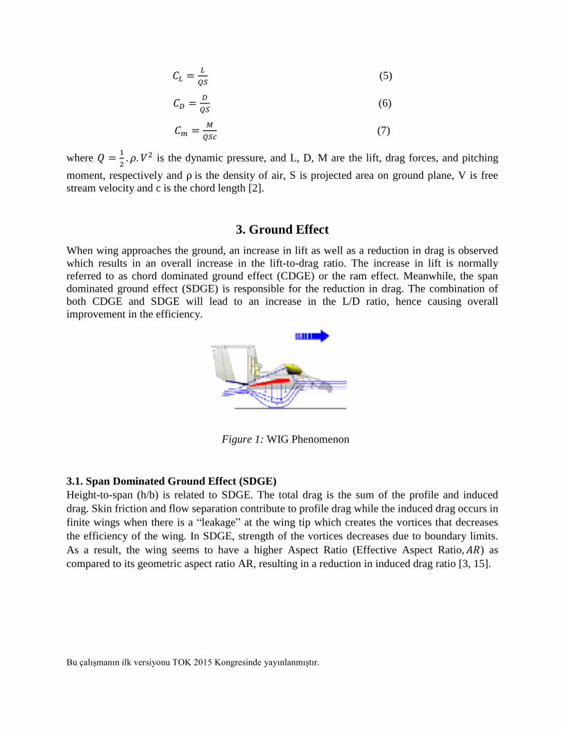
(5)
(6)
(7)
where
is the dynamic pressure, and L, D, M are the lift, drag forces, and pitching
moment, respectively and is the density of air, S is projected area on ground plane, V is free
stream velocity and c is the chord length [2].
3. Ground Effect
When wing approaches the ground, an increase in lift as well as a reduction in drag is observed
which results in an overall increase in the lift-to-drag ratio. The increase in lift is normally
referred to as chord dominated ground effect (CDGE) or the ram effect. Meanwhile, the span
dominated ground effect (SDGE) is responsible for the reduction in drag. The combination of
both CDGE and SDGE will lead to an increase in the L/D ratio, hence causing overall
improvement in the efficiency.
3.1. Span Dominated Ground Effect (SDGE)
Height-to-span (h/b) is related to SDGE. The total drag is the sum of the profile and induced
drag. Skin friction and flow separation contribute to profile drag while the induced drag occurs in
finite wings when there is a “leakage” at the wing tip which creates the vortices that decreases
the efficiency of the wing. In SDGE, strength of the vortices decreases due to boundary limits.
As a result, the wing seems to have a higher Aspect Ratio (Effective Aspect Ratio ) as
compared to its geometric aspect ratio AR, resulting in a reduction in induced drag ratio [3, 15].
Figure 1: WIG Phenomenon

Bu çalışmanın ilk versiyonu TOK 2015 Kongresinde yayınlanmıştır.
Figure 2: Vortex of an Aircraft in Flight a) Out of Ground Effect, b) In Ground Effect [3].
Span dominated ground effect was first studied by Wieselsberger [3]. The theory has been
developed by the methods of [15] and of [5] and [6]. All employ the assumption that the effects
of the ground on a wing are the same as the effect which would be induced by the flow about an
identical image wing symmetrically disposed with respect to the real wing on the opposite side
of the ground plane. Weisselsberger’s model predicts the increase of lift by assuming that the
induced drag is reduced because of the proximity to the ground measured by a parameter,
(8)
In another paper, this is simplified as
(9)
where the ground effect influence parameter is, is the height above the ground surface
and b is the wing span.
Figure 3: Sigma vs height
Bu çalışmanın ilk versiyonu TOK 2015 Kongresinde yayınlanmıştır.
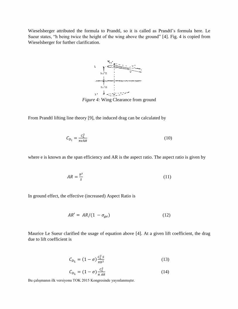
Wieselsberger attributed the formula to Prandtl, so it is called as Prandtl’s formula here. Le
Sueur states, “h being twice the height of the wing above the ground” [4]. Fig. 4 is copied from
Wieselsberger for further clarification.
Figure 4: Wing Clearance from ground
From Prandtl lifting line theory [9], the induced drag can be calculated by
(10)
where e is known as the span efficiency and AR is the aspect ratio. The aspect ratio is given by
(11)
In ground effect, the effective (increased) Aspect Ratio is
(12)
Maurice Le Sueur clarified the usage of equation above [4]. At a given lift coefficient, the drag
due to lift coefficient is
(13)
(14)
Bu çalışmanın ilk versiyonu TOK 2015 Kongresinde yayınlanmıştır.
In the presence of ground effect, Rozhdestvensky [1] has also shown that drag will reduce in
proportion to height and span efficiency is inversely to proportional to height.
,
The lift curve formula in Von Mises page 243 [6], is
=
(15)
Further manipulation [6] results in
(16)
Along with the camber and flaps, an additional term is needed [8]:
(17)
The CL0 is the lift coefficient at zero angle of attack. Here we can see the effect of AR on lift. By
Wieselsberger the resulting changes in angle of attack (AoA) and drag coefficient at a constant
lift coefficient are expressed by the equations
(Deg) (18)
(19)
Except the effect of the trailing vortices (Wieselsberger considered only the effect of the trailing
vortices of the image wing) the method of references [5] and [6] takes also wing thickness, the
effects of the bound vortices circulation and the longitudinal velocity into account. With these
factors, the formula is:
Bu çalışmanın ilk versiyonu TOK 2015 Kongresinde yayınlanmıştır.
-rB+ (20)
(21)
where T takes account of the reduction in longitudinal velocity. It is the effective change in angle
of attack due to the change in circulation, r is the appropriate factor for reducing B and Ke is the
effect of wing thickness, e being the ratio of maximum thickness to chord. CDa is the wing drag
coefficient corresponding to the given lift coefficient under free-air conditions. It is the slope of
the lift curve,
for the infinite span
(22)
Here h and c are the height of the quarter-chord point and the chord of the wing, respectively.
For computing B reference 4 can be used. The factor r is given by the relation
(23)
The quantity K is expressed by
(24)
3.2. Chord Dominated Ground Effect (CDGE)
The chord dominated ground effect is related to the suction side of the airfoil. A fact found by
designers dictates the suction side of airfoil be flat to improve the chord dominated ground
effect. However, this effect (sometimes termed as extreme ground effect) is very complicated to
model, as it is a strong function of the geometry of the entire vehicle. All in all, one can use the
GE parameter in lift force.

Bu çalışmanın ilk versiyonu TOK 2015 Kongresinde yayınlanmıştır.
In the study of CDGE, one of the main parameters is the height-to-chord (h/c) ratio. The term h
height here is distance from the ground surface and the airfoil or the wing. The increase in lift is
because the increase in static pressure which causes an air cushion at low heights. This ramming
effect leads to the higher lift. Fig. 5 below shows the difference between an airfoil without
ground effect (a) and with ground effect (b). Theoretically, as the height becomes 0, resulting in
stagnant air creating the highest possible static pressure with a unity value of coefficient of
pressure [15].
Rozhdestvensky had predicted for the case of flat plate with infinite span in the presence of
extreme ground effect , a closed form solution for and can be obtained by a
modification to the thin airfoil theory [1] and the solutions are given as
(25)
(26)
Figure 5: Contour Plot of Static Pressure on an Air
Foil a) Out of Ground Effect, b) In Ground Effect
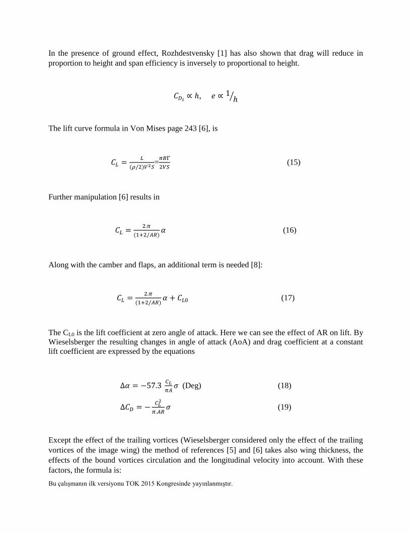
Figure 6: Ground Effect and Some Important Factors
Bu çalışmanın ilk versiyonu TOK 2015 Kongresinde yayınlanmıştır.
4. 6DOF Non Linear Dynamical Model
This part covers the development of a 6-DOF nonlinear dynamical model of the WIG craft. This
model includes the aerodynamics, mass-inertia, propulsion, atmospheric and gravity models. The
nonlinear equations of motion are developed by applying Newton’s second law and the law of
conservation of linear momentum. The equations are written in a body-fixed axis system, which
moves with the airplane and which has its origin at the airplane center of mass. The vehicle is
assumed to be a rigid body with six degrees of freedom. Three translational degrees describe the
motion of the center of mass and three attitude degrees describe the orientation of the vehicle.
Plane XZ is a plane of symmetry of the airplane [10, 11]. It is assumed that, mass of vehicle is
constant, Earth is fixed (no rotation), and curvature of the earth is neglected.
Figure 7: Ground Effect and Some Other Important Factors
Bu çalışmanın ilk versiyonu TOK 2015 Kongresinde yayınlanmıştır.
4.1. Equations of motion
The equations of motion for the vehicle can be developed by writing Newton’s second law for
each differential element of mass in the vehicle,
(27)
then integrating over the entire vehicle. During working out the acceleration of each mass
element, the contributions to its velocity from both linear velocities (u, v, w) in each of the
coordinate directions, as well as the ~ Ω × ~r contributions due to the rotation rates (p, q, r) about
the axes are taken into account.
The first task in above realizing equation is to define the inertial acceleration components
resulting from the application of disturbing force components to the aircraft. Consider the motion
referred to an orthogonal axis set (oxyz) with the origin o coincident with the cg of the vehicle.
The body, and hence the axes, are assumed to be in motion with respect to an external reference
frame such as earth (or inertial) axes. The components of velocity and force along the axes ox,
oy and oz are denoted as (U, V, W) and (X, Y, Z), respectively. The components of angular
velocity and moment about the same axes are denoted by (p, q, r) and (L, M, N), respectively.
The point p is an arbitrarily chosen point within the body with coordinates (x, y, z). The local
components of velocity and acceleration at p relative to the body axes are denoted as (u, v, w)
and (ax, ay, az), respectively. The velocity components at p relative to o are given by
(28)
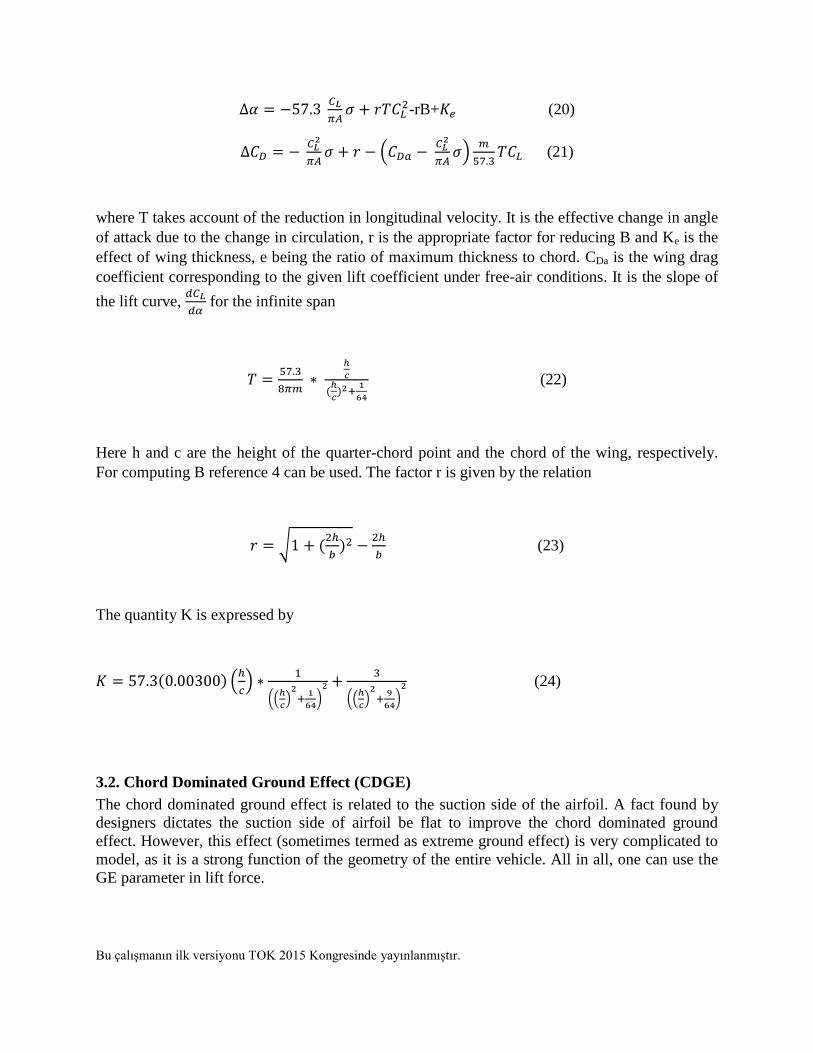
Figure 8: Motions and Angles

Bu çalışmanın ilk versiyonu TOK 2015 Kongresinde yayınlanmıştır.
Since the body in Fig. 8, is assumed to be rigid, so that, Then (28) is converted
to:
(29)
The resultant components of total force acting on the rigid body are given by:
(30)
where is the total is mass of the body, are the total force components acting on the
body and are the velocity components. The moment equations can also be derived as
follows:
(31)
The rotational kinematic equations, which relate Euler angular rates to body-axis angular rates,
are given by
(32)
where are the pitch, row and yaw attitude angles, respectively. The navigation equations
relate aircraft translational velocity components in body axes to earth-axis components,
neglecting wind effects. These differential equations describing the time evolution of the position
of the aircraft center of gravity relative to earth axes are given as follows:
Bu çalışmanın ilk versiyonu TOK 2015 Kongresinde yayınlanmıştır.
(33)
where and are the earth axis positions [10, 11]
4.2. Force and Moment equations
Further development of the equations of motion requires that the terms on the right hand side of
the equations adequately describe the disturbing forces and moments. The traditional approach,
after Bryan (1911), is to assume that the disturbing forces and moments are due to aerodynamic
effects, gravitational effects and movement of aerodynamic controls. Therefore, we may have:
(34)
4.3. Gravity Model
The gravitational force components in the small perturbation equations of motion are given by:
(35)
4.4. Aerodynamics
The airplane is assumed to be built up from a number of components. The total forces and
moments, which act on the airplane, are then assumed to follow from summing the forces and
moments, which act on these components [10, 11]. In these terms, aerodynamic coefficients can
be expressed as follows:
Bu çalışmanın ilk versiyonu TOK 2015 Kongresinde yayınlanmıştır.
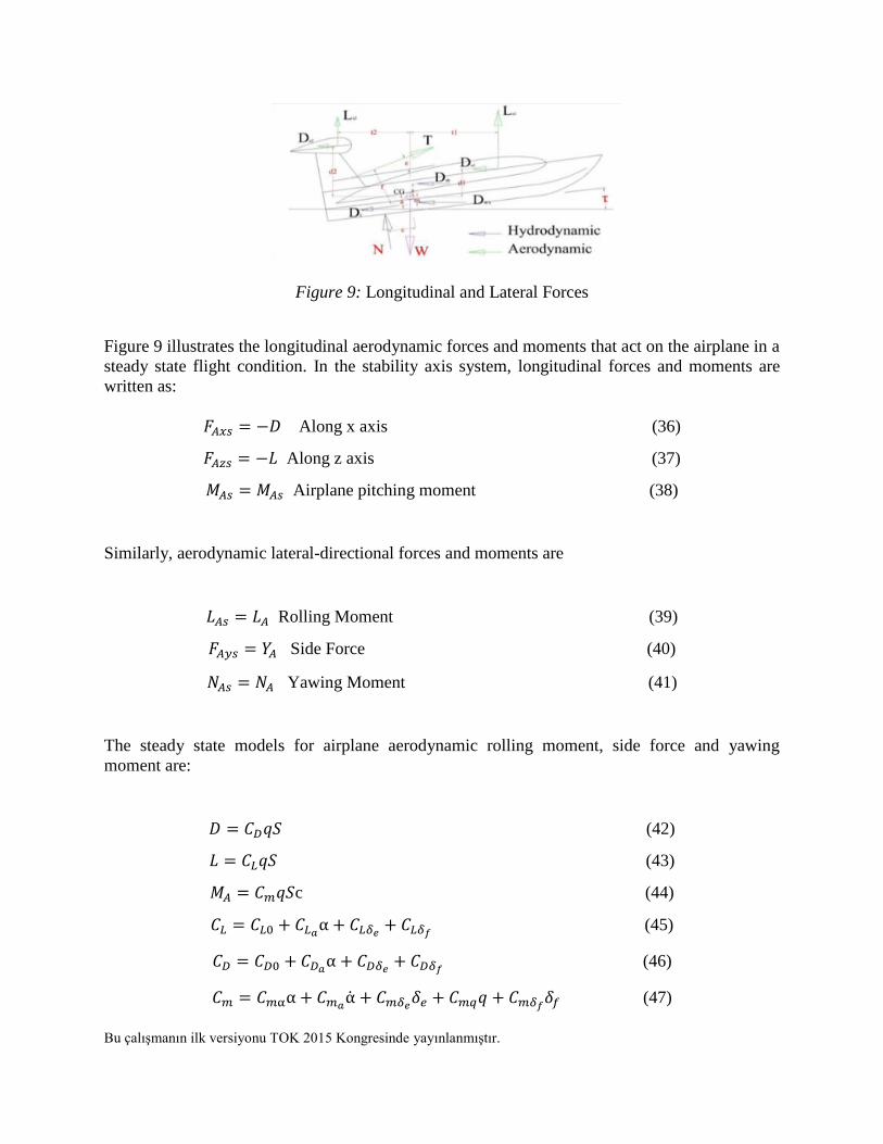
Figure 9: Longitudinal and Lateral Forces
Figure 9 illustrates the longitudinal aerodynamic forces and moments that act on the airplane in a
steady state flight condition. In the stability axis system, longitudinal forces and moments are
written as:
Along x axis (36)
Along z axis (37)
Airplane pitching moment (38)
Similarly, aerodynamic lateral-directional forces and moments are
Rolling Moment (39)
Side Force (40)
Yawing Moment (41)
The steady state models for airplane aerodynamic rolling moment, side force and yawing
moment are:
(42)
(43)
c (44)
(45)
(46)
(47)
Bu çalışmanın ilk versiyonu TOK 2015 Kongresinde yayınlanmıştır.
the change of airplane drag due to change in airplane angle of attack,
is the change of airplane drag due to change in
is the change of airplane drag due
to change in
is the change of airplane lift due to change in airplane angle of attack,
is the change of airplane lift due to change in ,
is the change of
airplane lift due to change in . Finally they can be written as:
(48)
(49)
(50)
(51)
(52)
(53)
4.5. Mass Inertia model
The mass inertia model contains some mass and geometric parameters of the craft. The mass is
lumped and is concentrated at the center of gravity (c.g.) location and the inertia tensor is
calculated with respect to the c.g. Predicted parameters for the vehicle are given below.
Wing Span: 4-5 m, Length: 2-3, Width of Fuselage: 0.3-0.5, Mass: 8-10 kg,
, , , .
The change of the gross weight and c.g. location of the WIG is neglected for simulation
purposes. Change in the c.g. location is very small, and its position moves towards the nose of
the airplane during the flight, increasing longitudinal stability of the aircraft. Moments of inertia
are considered to be constant at all times of simulation.
4.6. Propulsion Finding required thrust for propelling the vehicle forward, depends on drag. Selection of
propulsion source depends on cruising speed. Here a simple model is presented. The modulus of
thrust is
Bu çalışmanın ilk versiyonu TOK 2015 Kongresinde yayınlanmıştır.
(54)
The symbol depends on the type of engine, the symbol is the air density. The modulus of the
aerodynamic velocity is represented by , with as a constant and representing the
position of the throttle, between 0 and 1 inclusive. The following values characterize
approximately the type of engine:
, for propeller propulsion and high bypass ratio turbofan,
, for turbojet engine with no fan,
, for turbojet engine with after burner,
, for the ram-jet
Engine is considered to deliver thrust T whose point of application M, has for coordinates
( ) in the body frame . The engine is positioned at pitch angle , and yaw angle .
For simplification, it is assumed that the engines are symmetric (at equal distance at y axis), is
very small, , and the angle , is low, and identical for all of the engines. Then, the
relations become
(55)
(56)
Since we are using two propellers, I = 2 [10].
4.7. Actuator Models The actuators servo are assumed to be a first order servo with a transfer function
(57)
Dynamics of control surfaces (elevator, ailerons etc) are assumed faster than dynamics of a WIG
vehicle. The bandwidth T is chosen as 30 rad/s. Elevator deflection is constrained up to ,
rudder and aileron deflections are limited to .
Bu çalışmanın ilk versiyonu TOK 2015 Kongresinde yayınlanmıştır.
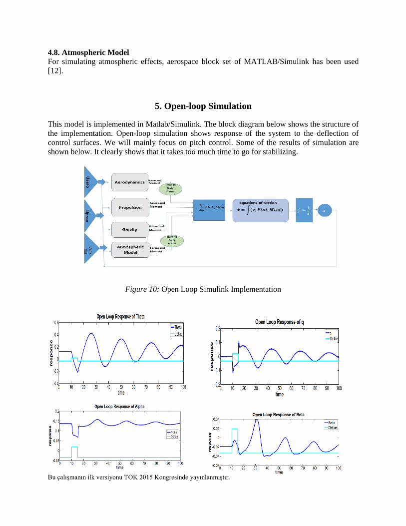
4.8. Atmospheric Model
For simulating atmospheric effects, aerospace block set of MATLAB/Simulink has been used
[12].
5. Open-loop Simulation
This model is implemented in Matlab/Simulink. The block diagram below shows the structure of
the implementation. Open-loop simulation shows response of the system to the deflection of
control surfaces. We will mainly focus on pitch control. Some of the results of simulation are
shown below. It clearly shows that it takes too much time to go for stabilizing.
Figure 10: Open Loop Simulink Implementation
Bu çalışmanın ilk versiyonu TOK 2015 Kongresinde yayınlanmıştır.
Figure 11: Some Results of Open Loop Simulation
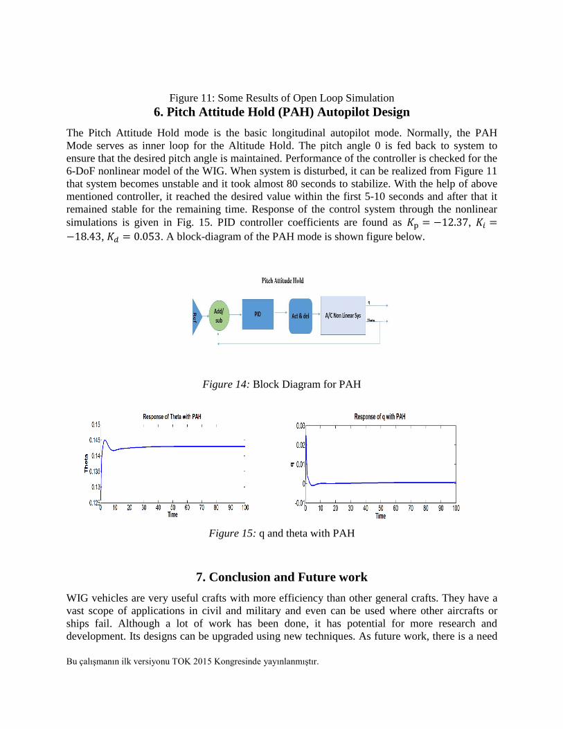
6. Pitch Attitude Hold (PAH) Autopilot Design
The Pitch Attitude Hold mode is the basic longitudinal autopilot mode. Normally, the PAH
Mode serves as inner loop for the Altitude Hold. The pitch angle 0 is fed back to system to
ensure that the desired pitch angle is maintained. Performance of the controller is checked for the
6-DoF nonlinear model of the WIG. When system is disturbed, it can be realized from Figure 11
that system becomes unstable and it took almost 80 seconds to stabilize. With the help of above
mentioned controller, it reached the desired value within the first 5-10 seconds and after that it
remained stable for the remaining time. Response of the control system through the nonlinear
simulations is given in Fig. 15. PID controller coefficients are found as ,
, . A block-diagram of the PAH mode is shown figure below.
Figure 14: Block Diagram for PAH
Figure 15: q and theta with PAH
7. Conclusion and Future work
WIG vehicles are very useful crafts with more efficiency than other general crafts. They have a
vast scope of applications in civil and military and even can be used where other aircrafts or
ships fail. Although a lot of work has been done, it has potential for more research and
development. Its designs can be upgraded using new techniques. As future work, there is a need

Bu çalışmanın ilk versiyonu TOK 2015 Kongresinde yayınlanmıştır.
for finding proper aero-dynamical coefficients. Roll and other autopilot designs are also required.
Finally whole design can be updated using robust control techniques.
References
[1] K.V. Rozhdestvensky, “Aerodynamics of a Lifting System in Extreme Ground Effect”, 1st
ed., Springer-Verlag, pages 63-67 and 263-280, 2000.
[2] J.D. Anderson Jr., “Fundamentals of Aerodynamics”, 3rd ed., McGraw-Hill, 2001.
[3] H. Akimoto, and S. Kubo, “Canard Type Wing-in-Surface-Effect-Ship’, 1st International
Symposium on WIG Crafts, Seoul, Korea, 2005
[4] Nicola de Divitiis, Performance and Stability of a Winged Vehicle in Ground Effect,
University of Rome “La Sapienza”, Rome, Italy 2009.
[5] M. Collu, M.H. Patel, F. Trarieux, “A Unified Mathematical Model for High Speed Hybrid
(Air and Water Borne) Vehicles. Cranfield University, UK, 2009.
[6] H. Akimoto, Y. Matsuzaki, Y. Ogawa, T. Taketsume, and S. Kubo, “Wind Tunnel
Measurement of 6-Component Forces and Moments Acting on a Model of New Wing-in-
Surface-Effect Craft of All-Wing Type for 8 Passengers”, 3rd Int. Euro-Conference on High-
Performance Marine Vehicles (HIPER’02), Bergen, Norway 2002.
[7] R. Von Mises, “Theory of Flight,” p. 243, republished by Dover, 1959.
[8] M.W. Olson and D. Richard “Ground Effect Determination of a Piper Comanche”, AIAA-
5316, 2003.
[9] L. Prandtl, “The Induced Drag of Multiplanes”, NACA TM No.182, 1924.
[10] J.L. Boiffier. “The Dynamics of Flight: The Equations”, Vol.1, August 24, 1998.
[11] B. Etkin, “Dynamics of Flight; Stability and Control” Wiley, New York, USA, 2nd edition,
1982.
[12] U.S. Standard Atmosphere, 1976, U.S. Government Printing Office, Washington, D.C.,
1976.
[13] L.P. Charles, R.D. Harbor, “Feedback Control Systems”, Prentice Hall, 1991.
[14] K.J. Astrom, T. Hagglund, “Advanced PID Control”, ISA-The Instrumentation, Systems,
and Automation Society, 2006.
[15] C.M. Hsiun, C. Kuang Chen, “Aerodynamic Characteristics of a two Dimensional Airfoil
with Ground Effect”, J. Aircraft, vol. 33. no. 2, pp. 386-392, 1996.
[16] C. Wieselsberger, “Wing Resistance near the Ground,” NACA TM No. 77, 1922.