Manual de instrucciones MULTÍMETRO3 contenido descripciÓn partes multímetro termopar puntas a t...
42
MUL-650 1018m V0.1 MULTÍMETRO PROFESIONAL BLUETOOTH Manual de instrucciones
Transcript of Manual de instrucciones MULTÍMETRO3 contenido descripciÓn partes multímetro termopar puntas a t...
MUL-650 1018m
V0.1
MULTÍMETROPROFESIONAL BLUETOOTH
Manual de instrucciones

1
IMPORTANTELea cuidadosamente este manual para evitar cualquier mal funcionamiento.La información que se muestra en este manual sirve únicamente como referencia sobre el producto. Debido a actualizaciones pueden existir diferencias.Por favor, consulte nuestra página web www.steren.com para obtener la versión más reciente de este manual.
PRECAUCIONES
NOTAS:
• El uso inapropiado de este multímetro puede causar daños, choque eléctrico o lesiones graves.
• Este producto NO es un juguete; Mantenga el multímetro fuera del alcance de los niños.
• Siempre retire los cables de prueba antes de reemplazar las baterías o los fusibles.
• Compruebe el estado de los cables de prueba y del medidor mismo antes de operarlo.
• No mida voltajes que excedan 1000V sobre tierra física; puede ser riesgoso.
• Tenga mucho cuidado al tomar medidas si los voltajes son mayores a 30 VCA RMS o 60 VCD; estos voltajes son considerados un peligro de descarga eléctrica.
• Siempre descargue los capacitores y corte la energía del dispositivo antes de realizar pruebas de diodo, resistencia o continuidad.
• Para evitar daños al multímetro, no exceda los límites máximos de los valores de entrada que se muestran en las especificaciones.
• En caso de un periodo prolongado de inactividad del equipo retire la batería.
• Este aparato NO está destinado a ser utilizado por personas con capacidades diferentes, a menos que cuenten con la preparación y supervisión adecuadas.
•No utilice el multímetro si la cubierta de la batería no está en su lugar y completamente cerrada.
“La operación de este equipo está sujeta a las siguientes dos condiciones: (1) es posible que este equipo o dispositivo no cause interferencia perjudicial y (2) este equipo o dispositivo debe aceptar cualquier interferencia, incluyendo la que pueda causar su operación no deseada.”
Este multímetro puede conectarse por medio de una aplicación para visualizar los datos de medición desde un smartphone. Por favor consulte el manual de instrucciones completo en nuestra página www.steren.com para saber cómo descargar la aplicación y vincularse vía Bluetooth.

2
ÍNDICE
CONTENIDO
DESCRIPCIÓN PARTESPERILLA DE SELECCIÓNSÍMBOLOS EN PANTALLA
COLOCAR LA BATERÍA
MODO DE USOCÓMO CONECTAR LOS CABLES DE PRUEBAMEDICIÓN DE VOLTAJE CON CORRIENTE DIRECTA Y CORRIENTE ALTERNAMEDICIÓN DE CORRIENTE DIRECTA Y CORRIENTE ALTERNAMEDICIÓN DE RESISTENCIAMEDICIÓN DE CAPACITANCIAMEDICIÓN DE FRECUENCIA Y PORCENTAJE DEL CICLO ÚTILMEDICIÓN DE TEMPERATURAPRUEBA DE BATERÍAPRUEBA DE DIODOS Y CONTINUIDAD
OTRAS FUNCIONES
ESPECIFICACIONES DE PRUEBAVOLTAJE DE CORRIENTE DIRECTAVOLTAJE DE CORRIENTE ALTERNACORRIENTE DIRECTACORRIENTE ALTERNARESISTENCIACAPACITANCIAFRECUENCIACICLO ÚTILTEMPERATURAPRUEBA DE BATERÍAPRUEBA DE DIODOS Y CONTINUIDAD
3
3345
6
66778899
1010
11
121212131313141414141515
3
CONTENIDO
DESCRIPCIÓN
PARTES
Multímetro Termopar Puntas
A
T TCOM
CAT.IV 600V
20A MAX FUSED400 mA MAX FUSED
CAT.III 1000VmA
V20AMAX 10 SEC.
Hz
SELECT HOLD RANGE REL
Hz
mA
A
A
V
OFF
Hz(IL 25mA)
Pantalla LCD
Perilla de selección
Terminal μAmA / y Temperatura “+”
Terminal 20 A
Terminal COM y Temperatura “-”
Sensor de iluminación
Modo relativo
Retener datos
Cambio de rangoSeleccionar tipo de
mediciónMedición de ciclo útil
Terminal VHz
4
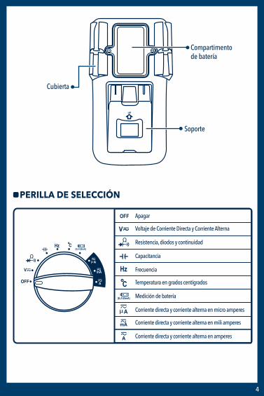
Compartimento de batería
Cubierta
Soporte
UP
PERILLA DE SELECCIÓN
Hz
mA
A
A
V
OFF
(IL 25mA)
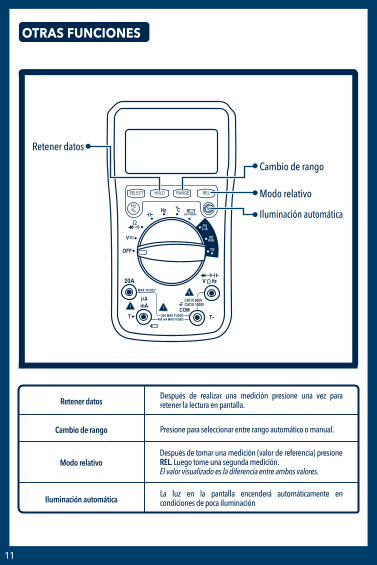
Corriente directa y corriente alterna en micro amperes
Corriente directa y corriente alterna en mili amperes
Corriente directa y corriente alterna en amperes
Frecuencia
Temperatura en grados centígrados
Medición de batería
Capacitancia
Apagar
Voltaje de Corriente Directa y Corriente Alterna
Resistencia, diodos y continuidad

5
SÍMBOLOS EN PANTALLA
1 2 3
4
5
67
11
10
8
12
9
1
2
3
4
5
6
7
8
9
Batería baja
Retención de datos
Modo relativo
Medición de ciclo útil
Grados: Celsius / Fahrenheit
Medición de transistores
10
Unidad de resistencia: Kilo ohms / mega ohms / ohms Unidad de frecuencia: Kilo hertz / mega hertz / hertz
12
Corriente alterna
Corriente directa
Diodos
11 Medición de continuidad
Unidad de voltaje: Volts / mili volts Unidad de corriente: Micro ampere / mili ampere / ampere Unidad de capacitancia: nanofaradio / micro faradio / mili faradio / faradio

6
COLOCAR LA BATERÍA
Retire los tornillos y la cubierta del compartimento de batería con ayuda de un desarmador, e inserte una batería “9 V”.
Asegúrese de colocar la polaridad de la batería correctamente.
Si el símbolo aparece en pantalla, significa que debe reemplazar la batería.
UP
UP
MODO DE USO
CÓMO CONECTAR LOS CABLES DE PRUEBAInserte el conector del cable negro en la terminal COM. Inserte el conector del cable rojo en las terminales 20 A, μ A mA o V Ω Hz.
A
T TCOM
CAT.IV 600V
20A MAX FUSED400 mA MAX FUSED
CAT.III 1000VmA
V20AMAX 10 SEC.
Hz
SELECT HOLD RANGE REL
Hz
mA
A
A
V
OFF
Hz(IL 25mA)
Cable rojoCable negro
• Para evitar el riesgo de descarga eléctrica, no conecte las puntas de prueba si la cubierta del multímetro no está en su lugar.
• La perilla de selección debe estar en la posición correcta para la prueba.
• Para evitar descargas eléctricas y daños en el multímetro, no exceda los valores máximos que se muestran en las especificaciones.
• Nunca cambie la posición de la perilla al azar durante la medición.
• Para evitar descargas eléctricas o daños en el multímetro, no intente tomar ninguna medida de tensión que supere los 60 VCD y 30 VCA.
• El fusible de protección sólo deberá ser sustituido por uno del mismo tipo y la misma especificación.
PRECAUCIONES DURANTE EL USO

7
CONTENIDO
DESCRIPCIÓN PARTESPERILLA DE SELECCIÓNSÍMBOLOS EN PANTALLA
COLOCAR LA BATERÍA
MODO DE USOCÓMO CONECTAR LOS CABLES DE PRUEBAMEDICIÓN DE VOLTAJE CON CORRIENTE DIRECTA Y CORRIENTE ALTERNAMEDICIÓN DE CORRIENTE DIRECTA Y CORRIENTE ALTERNAMEDICIÓN DE RESISTENCIAMEDICIÓN DE CAPACITANCIAMEDICIÓN DE FRECUENCIA Y PORCENTAJE DEL CICLO ÚTILMEDICIÓN DE TEMPERATURAPRUEBA DE BATERÍAPRUEBA DE DIODOS Y CONTINUIDAD
OTRAS FUNCIONES
ESPECIFICACIONES DE PRUEBAVOLTAJE DE CORRIENTE DIRECTAVOLTAJE DE CORRIENTE ALTERNACORRIENTE DIRECTACORRIENTE ALTERNARESISTENCIACAPACITANCIAFRECUENCIACICLO ÚTILTEMPERATURAPRUEBA DE BATERÍAPRUEBA DE DIODOS Y CONTINUIDAD
1
2
3
NOTAS:1. “ ” Significa que no puede introducir más de 1 000 V; es posible que se muestre un voltaje más alto, pero puede dañar elcircuito o producir una descarga eléctrica.2. Tenga cuidado con las descargas eléctricas al medir voltaje alto.
MEDICIÓN DE VOLTAJE DE CORRIENTE DIRECTAY CORRIENTE ALTERNA
Conecte el cable de prueba negro a la terminal COM y el rojo a la terminal V Ω Hz.
Gire la perilla a la posición V , para medir el voltaje de CD (Corriente Directa). Si desea medir el voltaje de CA (Corriente Alterna), presione el botón "SELECT".
Toque con las puntas el circuito. El valor de la medición aparecerá en pantalla.
Cable rojo
Cable negro
A
T TCOM
CAT.IV 600V
20A MAX FUSED400 mA MAX FUSED
CAT.III 1000VmA
V20AMAX 10 SEC.
Hz
SELECT HOLD RANGE REL
Hz
mA
A
A
V
OFF
Hz(IL 25mA)
1
2
3
Conecte el cable de prueba negro en la terminal COM y el rojo en la terminalμA mA para medir una corriente máxima de 400 mA. Para medir una corriente máxima de 2 A o 20 A, conecte el cable rojo en la terminal 20 A.
Gire la perilla a la posición μA, mA o A según sea necesario. Si desea medir Corriente Directa. Si desea medir CA (Corriente Alterna), presione el botón "SELECT".
Toque con las puntas el circuito. El valor de la medición aparecerá en pantalla.
Cable rojoCable negro
A
T TCOM
CAT.IV 600V
20A MAX FUSED400 mA MAX FUSED
CAT.III 1000VmA
V20AMAX 10 SEC.
Hz
SELECT HOLD RANGE REL
Hz
mA
A
A
V
OFF
Hz(IL 25mA) NOTAS:
1. Si en pantalla aparece "OL", significa que el valor de entrada supera el rango seleccionado. 2. " " significa que la corriente máxima del mA del enchufe es 400 mA y la corriente máxima es 20 A, si la medición es sobre 400 mA se protegerá por el fusible pero si la corriente es mayor a 20 A el fusible se quemará.
MEDICIÓN DE CORRIENTE DIRECTA Y CORRIENTE ALTERNA

8
1
2
3
Conecte el cable de prueba negro en la terminal COM y el rojo en la terminal V Ω Hz.
Gire la perilla a la posición
Toque con las puntas el circuito. El valor de la medición aparecerá en pantalla.
NOTAS:1. Si mide resistencias mayores a 1 MΩ el multímetro puede tardar unos segundos en obtener una lectura estable. 2. Cuando la terminal no está conectada, es decir, en circuito abierto, el icono “OL” se mostrará en pantalla indicando que está sobre el rango.3. Asegúrese de que los circuitos se encuentren sin energía y los capacitores completamente descargados para evitar choques eléctricos o daños en el equipo.
MEDICIÓN DE RESISTENCIA
Cable rojo
Cable negroA
T TCOM
CAT.IV 600V
20A MAX FUSED400 mA MAX FUSED
CAT.III 1000VmA
V20AMAX 10 SEC.
Hz
SELECT HOLD RANGE REL
Hz
mA
A
A
V
OFF
Hz(IL 25mA)
1
2
3
Conecte el cable de prueba negro en laterminal COM y el rojo en la terminal V Ω Hz.
Gire la perilla a la posición
Toque con las puntas el circuito o alambre que desee comprobar. El valor de la medición aparecerá en pantalla.
Cable rojo
Cable negroA
T TCOM
CAT.IV 600V
20A MAX FUSED400 mA MAX FUSED
CAT.III 1000VmA
V20AMAX 10 SEC.
Hz
SELECT HOLD RANGE REL
Hz
mA
A
A
V
OFF
Hz(IL 25mA)
NOTA:Asegúrese de que los circuitos se encuentren sin energía y los capacitores completa¬mente descargados para evitar choques eléctricos o daños en el equipo.
MEDICIÓN DE CAPACITANCIA

9
1
3
2
4
Conecte el cable de prueba negro en la terminal COM y el rojo en la terminal V Ω Hz.
Gire la perilla a la posición Hz.
Presione el botón "Hz / %" para elegir la prueba de frecuencia o el porcentaje del ciclo útil.
Toque con las puntas el circuito. El valor de la medición aparecerá en pantalla.
MEDICIÓN DE FRECUENCIA Y PORCENTAJE DEL CICLO ÚTIL
Cable rojo
Cable negroA
T TCOM
CAT.IV 600V
20A MAX FUSED400 mA MAX FUSED
CAT.III 1000VmA
V20AMAX 10 SEC.
Hz
SELECT HOLD RANGE REL
Hz
mA
A
A
V
OFF
Hz(IL 25mA)
1
2
3
Inserte el conector negro del termopar en la terminal T- e inserte el conector rojo en la terminal T+
Gire la perilla a la posición ºC.
Toque con la punta la pieza cuya temperatura desea medir; mantenga el contacto hasta que la lectura se estabilice.
MEDICIÓN DE TEMPERATURA
Conector negro
A
T TCOM
CAT.IV 600V
20A MAX FUSED400 mA MAX FUSED
CAT.III 1000VmA
V20AMAX 10 SEC.
Hz
SELECT HOLD RANGE REL
Hz
mA
A
A
V
OFF
Hz(IL 25mA)
Conector rojo

10
Cable rojo
Cable negroA
T TCOM
CAT.IV 600V
20A MAX FUSED400 mA MAX FUSED
CAT.III 1000VmA
V20AMAX 10 SEC.
Hz
SELECT HOLD RANGE REL
Hz
mA
A
A
V
OFF
Hz(IL 25mA)
NOTA:Asegúrese de que los circuitos se encuentren sin energía y los capacitores completamente descargados para evitar choques eléctricos o daños en el equipo.
1
2
3
Conecte el cable de prueba negro en la terminal COM y el rojo en la terminal
Gire la perilla a la posición
Toque con las puntas las terminales de la batería. El valor de la medición aparecerá en pantalla.
PRUEBA DE BATERÍA
Cable negroA
T TCOM
CAT.IV 600V
20A MAX FUSED400 mA MAX FUSED
CAT.III 1000VmA
V20AMAX 10 SEC.
Hz
SELECT HOLD RANGE REL
Hz
mA
A
A
V
OFF
Hz(IL 25mA)
Cable rojo
1
2
3
4
Conecte el cable de prueba negro en la terminal COM y el rojo en la terminal V Ω Hz.
Gire la perilla en la posición
Presione el botón “SELECT” para seleccionar medición de diodos o continuidad.
Para medir diodos conecte las puntas al componente semiconductor: la roja al ánodo y la negra al cátodo.Para medir continuidad toque con las puntas el circuito o alambre que desee comprobar.El valor de la medición aparecerá en pantalla.
PRUEBA DE DIODOS Y CONTINUIDAD
11
OTRAS FUNCIONES
A
T TCOM
CAT.IV 600V
20A MAX FUSED400 mA MAX FUSED
CAT.III 1000VmA
V20AMAX 10 SEC.
Hz
SELECT HOLD RANGE REL
Hz
mA
A
A
V
OFF
Hz(IL 25mA) Iluminación automática
Modo relativo
Retener datos
Cambio de rango
Después de realizar una medición presione una vez para retener la lectura en pantalla.Retener datos
Presione para seleccionar entre rango automático o manual. Cambio de rango
Después de tomar una medición (valor de referencia) presione REL. Luego tome una segunda medición. El valor visualizado es la diferencia entre ambos valores.
Modo relativo
La luz en la pantalla encenderá automáticamente en condiciones de poca iluminación Iluminación automática
12
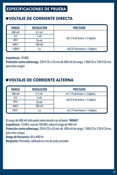
1 000 V 1 V ±(0, 8 % de lectura + 2 dígitos)
RANGO RESOLUCIÓN PRECISIÓN
VOLTAJE DE CORRIENTE DIRECTA
Impedancia: 10 MΩProtección contra sobrecarga: 250 V CD o CA rms de 400 mV de rango, 1 000 CD o 750 V CA rms para otros rangos
ESPECIFICACIONES DE PRUEBA
400 mV 0,1 mV 4 V 1 mV
10 mV 100 mV
40 V
400 V
±(0, 5 % de lectura + 2 dígitos)
750 V 1 V ±(1, 2 % de lectura + 3 dígitos)
RANGO RESOLUCIÓN PRECISIÓN
VOLTAJE DE CORRIENTE ALTERNA
El rango de 400 mV sólo podrá seleccionarlo con el botón “RANGE”.Impedancia: 10 MΩ, mas de 100 MΩ sobre el rango de 400 mV Protección contra sobrecarga: 250 V CD o CA rms de 400 mV de rango, 1 000 CD o 750 V CA rms para otros rangosRango de frecuencia: 40 a 400 HzRespuesta: Promedio, calibrado en rms de onda senoidal
400 mV 0.1 mV 4 V 1 mV
10 mV 100 mV
40 V
400 V
±(0, 8 % de lectura + 3 dígitos)
±(1, 2 % de lectura + 3 dígitos)

13
PRECISIÓN
4 A 1 mA20 A 10 mA
RANGO RESOLUCIÓN
CORRIENTE DIRECTA
Protección contra sobrecarga: 400 mA / Fusible 250 V Fusible F-20 A /250 V, 20 A hasta 10 segundos
400 μA 0,1μA4 000 μA 1μA
10 μA100 μA
40 mA
400 mA
±(1, 2 % de lectura + 2 dígitos)
±(2, 0 % de lectura + 3 dígitos)
PRECISIÓN
4 A 1 mA20 A 10 mA
RANGO RESOLUCIÓN
CORRIENTE ALTERNA
Protección contra sobrecarga: 400 mA / Fusible 250 V Fusible F-20 A / 250 V, 20 A hasta 10 segundosRango de frecuencia: 40 a 400 Hz
400 μA 0,1μA4 000 μA 1μA
10 μA100 μA
40 mA
400 mA
±(1, 5 % de lectura + 3 dígitos)
±(2, 5 % de lectura + 5 dígitos)
PRECISIÓN
4 MΩ 1 kΩ40 MΩ 10 kΩ
RANGO RESOLUCIÓN
RESISTENCIA
Protección contra sobrecarga: 250 V CD o CA rms
400 Ω 0,1Ω4 kΩ 1Ω
10 Ω100 Ω
40 kΩ
400 kΩ±(1, 0 % de lectura + 2 dígitos)
±(1, 0 % de lectura + 3 dígitos)
±(1, 5 % de lectura + 3 dígitos)

14
150 1 000 ºC
0,1 % 99, 9 % ± ( 2, 0 % de lectura + 2 dígitos ), Frecuencia inferior a 10 kHz Sensibilidad: onda senoidal 0, 6 V rms Protección contra sobrecarga: 250 V CD o CA rms
RESOLUCIÓNRANGO PRECISIÓN
TEMPERATURA
ºC 1 ºC-20 150 ºCa
a±(3 ºC + 1 dígito)
±(3 % de lectura + 2 dígitos)
PRECISIÓN
51, 2 kHz 10 Hz
512 kHz 100 Hz
5,12 MHz 1 kHz
RANGO RESOLUCIÓN
FRECUENCIA
Sensibilidad: onda senoidal 0, 6 V rms (5, 12 MHz: 1, 5 V rms)Protección contra sobrecarga: 250 V CD o CA rms
5, 12 Hz 0, 001 Hz51, 2 Hz 0, 01 Hz
0, 1 Hz1 Hz
512 Hz
5,12 kHz ±(0, 1 % de lectura + 5 dígitos)
PRECISIÓN
4 100 μF 100 nF
RANGO RESOLUCIÓN
CAPACITANCIA
Protección contra sobrecarga: 250 V CD o CA rms
51, 2 nF 10 pF512 nF 100 pF
1 nF10 nF
5, 12 μF
51, 2 μF±(2, 5 % de lectura + 5 dígitos)
±(3, 0 % de lectura + 10 dígitos)
±(5, 0 % de lectura + 10 dígitos)
CICLO ÚTIL

15
CONDICIÓN DE PRUEBARANGO PRECISIÓN
PRUEBA DE BATERÍA
Corriente de carga:Aprox. 25 mA
±(5, 0 % de lectura + 5 dígitos)
Rango de voltaje de batería: 1, 5 V ~ 12 VProtección contra sobrecarga: 400 mA / Fusible 250 V
Rango de voltaje de batería: 1, 5 V ~ 12 VProtección de sobrecarga: 250 V CD o CA rms
CONDICIÓN DE PRUEBARANGO DESCRIPCIÓN
PRUEBA DE DIODOS Y CONTINUIDAD
Corriente directa aprox. 0, 4 mAVoltaje invertido aprox. 1, 5 VLectura aproximada de voltaje de diodo
Sonará un zumbido si la resistencia es menor a 100 Ω
Voltaje de circuito abierto aprox. 0, 5 V
APLICACIÓN PARA ANDROID Y IPHONE
El Multímetro tiene la función de salida de datos en serie. Puede ser conectado con el teléfono móvil por Bluetooth, así que los datos del multímetro se pueden registrar, analizar, y procesar por la APP del teléfono móvil. Antes de utilizar esta función, debe instalar la APP del teléfono móvil. Para android descárguela en PLAY STORE y para iphone en Appstore.
NOTA: La APP del teléfono móvil se puede instalar en sistema iOS 4S ó superiores.
NOTA: La APP del teléfono móvil se puede instalar en sistema android 4.30 ó superiores.
Aplicación para android
Aplicación para iphone
Bluetooth Multimeter
Bluetooth Multimeter
16
1
2
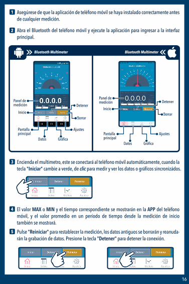
Asegúrese de que la aplicación de teléfono móvil se haya instalado correctamente antes de cualquier medición.
Abra el Bluetooth del teléfono móvil y ejecute la aplicación para ingresar a la interfaz principal.
3 Encienda el multímetro, este se conectará al teléfono móvil automáticamente, cuando la tecla "Iniciar" cambie a verde, de clic para medir y ver los datos o gráficos sincronizádos.
4 El valor MAX o MIN y el tiempo correspondiente se mostrarán en la APP del teléfono móvil, y el valor promedio en un período de tiempo desde la medición de inicio también se mostrará.
5 Pulse "Reiniciar" para restablecer la medición, los datos antiguos se borrarán y reanuda-rán la grabación de datos. Presione la tecla "Detener" para detener la conexión.
Panel demedición
Inicio
Detener
Borrar
Pantalla principal
Gráfica
Ajustes
Datos
Panel demedición
Inicio
Detener
Borrar
Pantalla principal
Gráfica
Ajustes
Datos
Bluetooth Multimeter Bluetooth Multimeter

17
6 Pulse en:Datos: para ver los datos y la hora. Gráfica: para ver el gráfico. Guardar: para guardar los datos o el gráfico. Inicio: para regresar a la interfaz principal.
Para visualizar los archivos guardados busque la carpeta con el nombre indicado al momento de guardar
Guardar
Para cambiar el tiempo de guardado de datos dirijase a la opción “Ajustes” y de clic en Tasa de datos
Ajustes
Aparecerá una barra que podrá deslizar y le indicara cuantas mediciones se guardaran por minuto
Ejemplo: 60 por minuto
1234567891011
17.317.317.317.317.317.317.317.317.317.317.3
DCV MVDCV MVDCV MVDCV MVDCV MVDCV MVDCV MVDCV MV1DCV MVDCV MVDCV MV
15:29:53:23415:29:54:23815:29:55:23815:29:56:27515:29:57:26515:29:58:26815:29:59:26815:30:00:27315:30:01:27715:30:02:27615:30:03:280
Datos
18
Alimentación: 9 V - - - (batería cuadrada)
Voltaje CD (V): 400 mV / 4 V / 40 V / 400 V ±(0,5%+2d) /1 000 V ±(0,8%+2d)
Voltaje CA (V) True-RMS: 4 V / 40 V / 400 V ±(0,8%+3d) / 750 V ±(1,2%+3d)
Corriente CD (A): 400 uA /4 000 uA / 40 mA / 400 mA ±(1,2%+2d)
Corriente CD (A): 4 A / 20 A ±(2%+3d)
Corriente CA (A): 400 uA / 4 000 uA / 40 mA / 400 mA ±(1,5%+3d)
Corriente CA (A): 4 A / 20 A ±(2,5%+5d)
Resistencia (Ω): 400 ±(1%+3d) / 4K / 40 K / 400 K / 4 M ±(1%+2d) / 40 M ±(1,5%+3d)
Capacitancia: 51,2 nF ±(3%+10d ) / 512 nF / 5,12 uF / 51,2 uF ±(2,5%+5d) /100 uF ±(5%+10d)
Frecuencia (Hz): 5,12 Hz /51,2 Hz / 512 Hz / 5,12 kHz / 512 kHz / 5,12 MHz ±(0.1%+5d)
Temperatura: -20 a 150 °C ±(3°C+1d) / 150 a 1 000 °C ±(3%+2d)
Temperatura de operación: 0 - 40 °C
Temperatura de almacenamiento: -20 a 60°C.
Consumo: 0,1 mW/h
Consumo en espera: No aplica
ESPECIFICACIONES

GARANTÍA Producto: Multímetro profesional BluetoothModelo: MUL-650Marca: Steren
Esta póliza garantiza el producto por el término de un año en todos sus componentes y mano de obra, contra cualquier defecto de fabricación y funcionamiento, a partir de la fecha de entrega.
CONDICIONES1.- Para hacer efectiva la garantía, presente esta póliza, o factura, o comprobante de compra y el producto, en donde fue adquirido o en Electrónica Steren S.A. de C.V.2.- Electrónica Steren S.A de C.V. se compromete a reparar el producto en caso de estar defectuoso sin ningún cargo al consumidor. Los gastos de transportación serán cubiertos por el proveedor.3.- El tiempo de reparación en ningún caso será mayor a 30 días, contados a partir de la recepción del producto en cualquiera de los sitios donde pueda hacerse efectiva la garantía.4.- El lugar donde puede adquirir partes, componentes, consumibles y accesorios, así como hacer válida esta garantía es en cualquiera de las direcciones mencionadas posteriormente.
DATOS DEL DISTRIBUIDORNombre del Distribuidor ____________________________________________________________Domicilio ______________________________________________________________________Número de serie _________________________________________________________________Fecha de entrega _________________________________________________________________
ELECTRÓNICA STEREN S.A. DE C.V.Biólogo Maximino Martínez No. 3408, San Salvador Xochimanca, Del. Azcapotzalco Ciudad de México 02870, RFC: EST850628-K51STEREN PRODUCTO EMPACADO S.A. DE C.V.Autopista México-Querétaro. Km 26.5 Sin número, Nave Industrial 3-A, Col. Lomas de Boulevares, Tlalnepantla de Baz, Estado de México, C.P. 54020, RFC: SPE-941215-H43
En caso de que su producto presente alguna falla, acuda al centro de distribución más cercano a su domicilio y en caso de tener alguna duda o pregunta por favor llame a nuestro Centro de Atención a Clientes, en donde con gusto le atenderemos en todo lo relacionado con su producto Steren.Centro de Atención a Clientes 01 800 500 9000
ESTA PÓLIZA NO SE HARÁ EFECTIVA EN LOS SIGUIENTES CASOS:1.- Cuando el producto ha sido utilizado en condiciones distintas a las normales.2.- Cuando el producto no ha sido operado de acuerdo con el instructivo de uso.3.- Cuando el producto ha sido alterado o reparado por personal no autorizado por Electrónica Steren S.A. de C.V. El consumidor podrá solicitar que se haga efectiva la garantía ante la propia casa comercial donde adquirió el producto. Si la presente garantía se extraviara, el consumidor puede recurrir a su proveedor para que le expida otra póliza, previa presentación de la nota de compra o factura respectiva.

MUL-650 1018m
V0.1
BLUETOOTHPROFESSIONAL MULTIMETER
Instruction manual

1
IMPORTANT
Read these manual to avoid any damage.The instructions of these manual are for reference about the product.There may be differences due to update.Please check our web site www.steren.com to obtain the latest version of the instruction manual.
CAUTIONS
NOTES:
• Improper use of this Multimeter can cause damage, electric shock, or serious injury.
• This product is not a toy; Keep the Multimeter out of the reach of children.
• Always remove test cables before replacing batteries or fuses.
• Check the condition of the test cables and the measurer itself before operating.
• Do not measure voltages exceeding 1000V above ground; Can be risky.
• Be very careful when taking measurements if the voltages are greater than 30 VAC RMS or
60 VDC; These voltages are considered a electric shock danger.
• Always discharge the capacitors and cut off the power of the device before performing diode, resistance or continuity tests.
• To avoid damage to the Multimeter, do not exceed the maximum limits of the input values shown in the specifications.
• In case of a prolonged period of inactivity, remove the battery.
• This appliance is NOT intended for use by persons with different capacities, unless properly prepared and supervised.
• Do not use the Multimeter if the battery cover is not in place and fully closed.
The operation of this device is subject to the following two conditions: (1) it is possible that this device may not cause harmful interference and (2) this device must accept any interference, including interference that may cause undesired operation.
This multimeter can be connected through an application to view the measurement data from a smartphone. Please refer to the complete instruction manual on our website www.steren.com to learn how to download the application and connect via Bluetooth.

2
INDEX
CONTENT
DESCRIPTIONPARTSSELECTION KNOBSYMBOLS IN SCREEN
PLACING BATTERY
HOW TO USEHOW TO CONNECT THE TEST CABLESVOLTAGE MEASUREMENT WITH DIRECT CURRENT AND ALTERNATE CURRENTDIRECT CURRENT AND ALTERNATE CURRENT MEASUREMENT RESISTANCE MEASUREMENTCAPACITANCE MEASUREMENT FREQUENCY AND PERCENTAGE OF THE WORKING CYCLE MEASUREMENT TEMPERATURE MEASUREMENTBATTERY TESTINGDIODES AND CONTINUITY TESTING
OTHER FUNCTIONS
TEST SPECIFICATIONSDIRECT CURRENT VOLTAGEALTERNATE CURRENT VOLTAGEDIRECT CURRENTALTERNATING CURRENTRESISTANCECAPACITANCEFREQUENCYWORKING CYCLETEMPERATUREBATTERY TESTINGDIODES AND CONTINUITY TESTING
3
3345
6
66778899
1010
11
121212131313141414141515

3
CONTENT
DESCRIPTION
PARTS
Multimeter Thermocouple Tips
A
T TCOM
CAT.IV 600V
20A MAX FUSED400 mA MAX FUSED
CAT.III 1000VmA
V20AMAX 10 SEC.
Hz
SELECT HOLD RANGE REL
Hz
mA
A
A
V
OFF
Hz(IL 25mA)
LCD screen
Selection knob
20 A Terminal
COM and Temperature “-”Terminal
Lighting Sensor
Relative mode
Hold data
Change RangeSelect measurement
typeWorking cycle measurement
VHz
μAmA / and Temperature “+” Terminal
Terminal

4
Battery compartment
Cover
Support
UP
SELECTION KNOB
Hz
mA
A
A
V
OFF
(IL 25mA)
Direct current and alternating current in micro amps
Direct current and alternating current in milli amps
Direct current and alternating current in amps
Frequency
Temperature in Celsius degrees
Battery Measurement
Capacitance
Turn off
Direct Current and Alternating Current Voltage
Resistance, diodes and continuity

5
SYMBOLS IN SCREEN
1 2 3
4
5
67
11
10
8
12
9
1
2
3
4
5
6
7
8
9
Low battery
Hold data
Relative mode
Working cycle measurement
Degrees: Celsius / Fahrenheit
Transistors measurement
10
Resistance unit: Kilo ohms / mega ohms / ohmsFrequency unit: Kilo hertz / mega hertz / hertz
12
Alternating current
Direct current
Diodes
11 Continuity measurement
Voltage unit: Volts / milli voltsCurrent unit: Micro ampere / mili ampere / ampereCapacitance unit: nano farad/ micro farad / mili farad / farad

6
PLACING BATTERY
Remove the screws and the battery compartment cover using a screwdriver, and insert a “9 V” battery.
Be sure to place the battery polarity correctly.
If the symbol appears on the screen, it means that you must replace the battery.
UP
UP
HOW TO USE
HOW TO CONNECT THE TEST CABLESInsert the black cable connector into the COM terminal.Insert the red cable connector on the 20 A, μA mA or V Ω Hz terminals.
A
T TCOM
CAT.IV 600V
20A MAX FUSED400 mA MAX FUSED
CAT.III 1000VmA
V20AMAX 10 SEC.
Hz
SELECT HOLD RANGE REL
Hz
mA
A
A
V
OFF
Hz(IL 25mA)
Red cableBlack cable
• To avoid the electric shock risk, do not connect the test tips if the Multimeter cover is not in place.
• The selection knob must be in the correct position for the test.
• To avoid electric shock and damage in the Multimeter, do not exceed the maximum values shown in the specifications.
• Never change the knob position of the at random during the measurement.
• To avoid electrical shock or damage in the Multimeter, do not attempt to take any voltage measurements exceeding 60 VDC and 30 VAC.
• The protective fuse must be only replaced by one of the same type and specification.
CAUTIONS DURING USING

7
CONTENT
DESCRIPTIONPARTSSELECTION KNOBSYMBOLS IN SCREEN
PLACING BATTERY
HOW TO USEHOW TO CONNECT THE TEST CABLESVOLTAGE MEASUREMENT WITH DIRECT CURRENT AND ALTERNATE CURRENTDIRECT CURRENT AND ALTERNATE CURRENT MEASUREMENT RESISTANCE MEASUREMENTCAPACITANCE MEASUREMENT FREQUENCY AND PERCENTAGE OF THE WORKING CYCLE MEASUREMENT TEMPERATURE MEASUREMENTBATTERY TESTINGDIODES AND CONTINUITY TESTING
OTHER FUNCTIONS
TEST SPECIFICATIONSDIRECT CURRENT VOLTAGEALTERNATE CURRENT VOLTAGEDIRECT CURRENTALTERNATING CURRENTRESISTANCECAPACITANCEFREQUENCYWORKING CYCLETEMPERATUREBATTERY TESTINGDIODES AND CONTINUITY TESTING
1
2
3
NOTES:1. “ ” It means that you can not enter more than 1000 V; a higher voltage may be displayed, but may damage the circuit or cause an electric shock.2. Be careful of electrical shocks when measuring high voltage.
VOLTAGE MEASUREMENT WITH DIRECT CURRENT AND ALTERNATE CURRENT
Connect the black test cable in to the COM terminal and the red test cable in to the V Ω Hz terminal.
Turn the knob to V position, to measure the DC (Direct Current) voltage. If you want to measure the AC (Alternating current) voltage, press the "SELECT" button.
Tap the circuit with tips. The measurement value will be displayed.
Red cable
Black cable
A
T TCOM
CAT.IV 600V
20A MAX FUSED400 mA MAX FUSED
CAT.III 1000VmA
V20AMAX 10 SEC.
Hz
SELECT HOLD RANGE REL
Hz
mA
A
A
V
OFF
Hz(IL 25mA)
1
2
3
Connect the black test cable to the COM terminal and the red test cable in to theμA mA to measure a maximum current of 400 mA. To measure a maximum current of 2 A or 20 A, connect the red wire to the 20 A terminal.
Turn the knob to μA, mA or A position as required.If you want to measure Direct Current. If you want to measure AC (Alternating Current), press the "SELECT" button.
Tap the circuit with tips. The measurement value will be displayed.
Red cableBlack cable
A
T TCOM
CAT.IV 600V
20A MAX FUSED400 mA MAX FUSED
CAT.III 1000VmA
V20AMAX 10 SEC.
Hz
SELECT HOLD RANGE REL
Hz
mA
A
A
V
OFF
Hz(IL 25mA) NOTES:
1. If "OL" appears in the display, means the input value exceeds the selected range.2. " " means that the mA maximum current of the plug is 400 mA and the maximum current 20 A , if the measurement is over 400 mA it will be protected by the fuse but if the current is greater than 20 A the fuse will be burn
DIRECT CURRENT AND ALTERNATE CURRENT MEASUREMENT

8
1
2
3
Connect the black test cable in to the COM terminal and the red test cable in to the V Ω Hz terminal.
Turn the knob to the position.
Tap the circuit with tips. The measurement value will be displayed.
NOTES:1. If you measure resistors greater than 1 MΩ, the Meter may take a few seconds to obtain a stable reading.2. When the terminal is not connected, it means, in open circuit, the“OL” icon will be displayed indicating that it is over the range.3. Make sure that the circuits are out of power and capacitors are fully discharged to prevent electrical shock or damage to the device.
RESISTANCE MEASUREMENT
Red cable
Black cableA
T TCOM
CAT.IV 600V
20A MAX FUSED400 mA MAX FUSED
CAT.III 1000VmA
V20AMAX 10 SEC.
Hz
SELECT HOLD RANGE REL
Hz
mA
A
A
V
OFF
Hz(IL 25mA)
1
2
3
Connect the black test cable in to the COM terminal and the red test cable in to the V Ω Hz terminal.
Turn the knob to the position.
Tap the circuit with tips or wire that you want to check. The measurement value will be displayed.
Red cable
Black cableA
T TCOM
CAT.IV 600V
20A MAX FUSED400 mA MAX FUSED
CAT.III 1000VmA
V20AMAX 10 SEC.
Hz
SELECT HOLD RANGE REL
Hz
mA
A
A
V
OFF
Hz(IL 25mA)
NOTE:Make sure that the circuits are out of power and the capacitors are fully discharged to prevent electric shocks or damages to the device.
CAPACITY MEASUREMENT
9
1
3
2
4
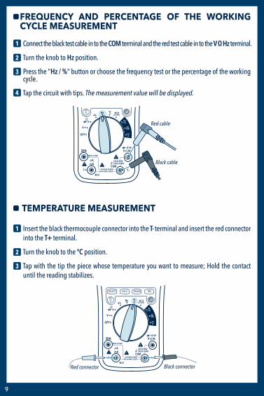
Connect the black test cable in to the COM terminal and the red test cable in to the V Ω Hz terminal.
Turn the knob to Hz position.
Press the "Hz / %" button or choose the frequency test or the percentage of the working cycle.
Tap the circuit with tips. The measurement value will be displayed.
FREQUENCY AND PERCENTAGE OF THE WORKING CYCLE MEASUREMENT
Red cable
Black cableA
T TCOM
CAT.IV 600V
20A MAX FUSED400 mA MAX FUSED
CAT.III 1000VmA
V20AMAX 10 SEC.
Hz
SELECT HOLD RANGE REL
Hz
mA
A
A
V
OFF
Hz(IL 25mA)
1
2
3
Insert the black thermocouple connector into the T- terminal and insert the red connector into the T+ terminal.
Turn the knob to the ºC position.
Tap with the tip the piece whose temperature you want to measure; Hold the contact until the reading stabilizes.
TEMPERATURE MEASUREMENT
Black connector
A
T TCOM
CAT.IV 600V
20A MAX FUSED400 mA MAX FUSED
CAT.III 1000VmA
V20AMAX 10 SEC.
Hz
SELECT HOLD RANGE REL
Hz
mA
A
A
V
OFF
Hz(IL 25mA)
Red connector

10
Red cable
Black cableA
T TCOM
CAT.IV 600V
20A MAX FUSED400 mA MAX FUSED
CAT.III 1000VmA
V20AMAX 10 SEC.
Hz
SELECT HOLD RANGE REL
Hz
mA
A
A
V
OFF
Hz(IL 25mA)
NOTE:Make sure that the circuits are out of power and the capacitors are fully discharged to prevent electric shocks or damages to the device.
1
2
3
Connect the black test cable in to the COM terminal and the red test lead in to the terminal
Turn the knob to the position.
Tap the circuit with tips. The measurement value will be displayed.
BATTERY TESTING
Black cableA
T TCOM
CAT.IV 600V
20A MAX FUSED400 mA MAX FUSED
CAT.III 1000VmA
V20AMAX 10 SEC.
Hz
SELECT HOLD RANGE REL
Hz
mA
A
A
V
OFF
Hz(IL 25mA)
Red cable
1
2
3
4
Connect the black test cable in to the COM terminal and the red test cable in to the V Ω Hz terminal.
Turn the knob to position.
Press the “SELECT” button to select diode or continuity measurement.
To measure diodes connect the tips to the semiconductor component: the red to the anode and the black to the cathode.To measure continuity, tap with tips the circuit or wire that you want to check. The measurement value will be displayed.
DIODES AND CONTINUITY TESTING

11
OTHER FUNCTIONS
A
T TCOM
CAT.IV 600V
20A MAX FUSED400 mA MAX FUSED
CAT.III 1000VmA
V20AMAX 10 SEC.
Hz
SELECT HOLD RANGE REL
Hz
mA
A
A
V
OFF
Hz(IL 25mA) Lighting sensor
Relative mode
Hold data
Change range
After performing a measurement press once to hold the reading on the screen.Hold data
Press to select between auto or manual range.Change range
After taking a measurement (reference value) press REL. Then take a second measurement.The displayed value is the difference between the two values.
Relative mode
The light on the screen will automatically turn on in low light conditions.Lighting sensor

12
1 000 V 1 V ±(0. 8 % of reading + 2 digits)
RANGE RESOLUTION ACCURACY
DIRECT CURRENT VOLTAGE
Impedance: 10 MΩOverload protection: 250 V DC or AC rms of 400 mV range, 1 000 DC or 750 V AC rms for other ranges
TEST SPECIFICATIONS
400 mV 0.1 mV 4 V 1 mV
10 mV 100 mV
40 V
400 V
±(0. 5 % of reading + 2 digits)
750 V 1 V ±(1. 2 % of reading + 3 digits)
RANGE RESOLUTION ACCURACY
ALTERNATING CURRENT VOLTAGE
The 400 mV range only select it with the button “RANGE”.Impedance: 10 MΩ, more than 100 MΩ over the 400 mV range Overload protection: 250 V DC or AC rms of 400 mV range, 1 000 DC or 750 V AC rms for other rangesFrequency range: 40 to 400 HzResponse: Average, calibrated in sine wave rms
400 mV 0.1 mV 4 V 1 mV
10 mV 100 mV
40 V
400 V
±(0. 8 % of reading + 3 digits)
±(1. 2 % of reading + 3 digits)

13
ACCURACY
4 A 1 mA20 A 10 mA
RANGE RESOLUTION
DIRECT CURRENT
Overload protection: 400 mA / 250 V Fuse F-20 A /250 V Fuse, 20 A up to10 seconds
400 μA 0.1μA4 000 μA 1μA
10 μA100 μA
40 mA
400 mA
±(1. 2 % of reading + 2 digits)
±(2. 0 % of reading + 3 digits)
ACCURACY
4 A 1 mA20 A 10 mA
RANGE RESOLUTION
ALTERNATING CURRENT
Overload protection: 400 mA / 250 V Fuse Fusible F-20 A / 250 V, 20 A up to10 secondsFrequency range: 40 up to 400 Hz
400 μA 0.1μA4 000 μA 1μA
10 μA100 μA
40 mA
400 mA
±(1. 5 % of reading + 3 digits)
±(2. 5 % of reading + 5 digits)
ACCURACY
4 MΩ 1 kΩ40 MΩ 10 kΩ
RANGE RESOLUTION
RESISTANCE
Overload protection: 250 V DC or AC rms
400 Ω 0.1Ω4 kΩ 1Ω
10 Ω100 Ω
40 kΩ
400 kΩ±(1. 0 % of reading + 2 digits)
±(1. 0 % of reading + 3 digits)
±(1. 5 % of reading + 3 digits)

14
150 1 000 ºC
0.1 % 99. 9 % ± ( 2. 0 % of reading + 2 digits ), Frequency less than 10 kHzSensitivity: sine wave 0. 6 V rms Overload protection: 250 V DC or AC rms
RESOLUTIONRANGE ACCURACY
TEMPERATURE
ºC 1 ºC-20 150 ºCto
to±(3 ºC + 1 digit)
±(3 % of reading + 2 digits)
ACCURACY
51. 2 kHz 10 Hz
512 kHz 100 Hz
5.12 MHz 1 kHz
RANGE RESOLUTION
FREQUENCY
Sensitivity: sine wave 0. 6 V rms (5. 12 MHz: 1. 5 V rms)Overload protection: 250 V DC or AC rms
5. 12 Hz 0. 001 Hz51. 2 Hz 0. 01 Hz
0. 1 Hz1 Hz
512 Hz
5,12 kHz ±(0. 1 % of reading + 5 digits)
ACCURACY
4 100 μF 100 nF
RANGE RESOLUTION
CAPACITANCE
Overload protection: 250 V DC or AC rms
51. 2 nF 10 pF512 nF 100 pF
1 nF10 nF
5. 12 μF
51. 2 μF±(2. 5 % of reading + 5 digits)
±(3. 0 % of reading + 10 digits)
±(5. 0 % of reading + 10 digits)
WORKING CYCLE
15
TEST CONDITIONRANGE ACCURACY
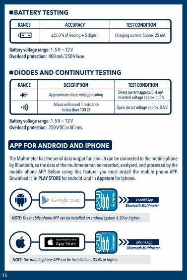
BATTERY TESTING
Charging current: Approx. 25 mA±(5. 0 % of reading + 5 digits)
Battery voltage range: 1. 5 V ~ 12 VOverload protection: 400 mA / 250 V Fuse
Battery voltage range: 1. 5 V ~ 12 VOverload protection: 250 V DC or AC rms
TEST CONDITIONRANGE DESCRIPTION
DIODES AND CONTINUITY TESTING
Direct current approx. 0. 4 mAInverted voltage approx. 1. 5 VApproximate diode voltage reading
A buzz will sound if resistanceis less than 100 Ω Open circuit voltage approx. 0.5 V
APP FOR ANDROID AND IPHONE
The Multimeter has the serial data output function. It can be connected to the mobile phone by Bluetooth, so the data of the multimeter can be recorded, analyzed, and processed by the mobile phone APP. Before using this feature, you must install the mobile phone APP. Download it in PLAY STORE for android and in Appstore for iphone.
NOTE: The mobile phone APP can be installed on iOS 4S or higher.
NOTE: The mobile phone APP can be installed on android system 4.30 or higher.
Android App
iphone App
Bluetooth Multimeter
Bluetooth Multimeter

16
1
2
Make sure that the mobile phone application has been installed correctly before any measurement.
Open the Bluetooth of the mobile phone and perform the application to enter in the main interface.
3 Turn on the multimeter, it will connect to the mobile phone automatically, when the "Iniciar" key changes to green color, click to measure and view synchronized data or graphics.
4 The MAX or MIN value and corresponding time will be displayed in the mobile phone APP, and the average value in a period of time from the start measurement will also be displayed.
5 Press "Reiniciar" to reset the measurement, the old data will be erased and data recording will resume. Press the "Detener" key to stop the connection.
Measuringpanel
Start
Stop
Main screen
Graphic
Settings
Data
ClearStart
Stop
Main screen
Graphic
Settings
Data
Measuringpanel
Clear
Bluetooth Multimeter Bluetooth Multimeter

17
6 Press:Datos: to view data and time.Gráfica: to view graphic. Guardar: to save data or graphic. Inicio: to return to the main interface.
To view saved files, search folder with the specified name when saving
To change the data saving time go to “Ajustes” and click on Tasa de datos
A slide bar will appear and will indicate how many measurements are saved per minute
Example: 60 per minute
Guardar
1234567891011
17.317.317.317.317.317.317.317.317.317.317.3
DCV MVDCV MVDCV MVDCV MVDCV MVDCV MVDCV MVDCV MV1DCV MVDCV MVDCV MV
15:29:53:23415:29:54:23815:29:55:23815:29:56:27515:29:57:26515:29:58:26815:29:59:26815:30:00:27315:30:01:27715:30:02:27615:30:03:280
Datos
Ajustes

18
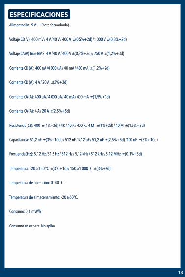
Input: 9 V - - - (square battery)
DC voltage (V): 400 mV / 4 V / 40 V / 400 V ±(0.5%+2d) / 1 000 V ±(0.8%+2d)
AC voltage (V) True-RMS: 4 V / 40 V / 400 V ±(0.8%+3d) / 750 V ±(1.2%+3d)
DC current (A): 400 uA / 4 000 uA / 40 mA / 400 mA ±(1.2%+2d)
DC current (A): 4 A / 20 A ±(2%+3d)
AC current (A): 400 uA / 4 000 uA / 40 mA / 400 mA ±(1.5%+3d)
AC current (A): 4 A / 20 A ±(2.5%+5d)
Resistance (Ω): 400 ±(1%+3d) / 4 K / 40 K / 400 K / 4 M ±(1%+2d) / 40 M ±(1.5%+3d)
Capacitance: 51.2 nF ±(3%+10d) / 512 nF / 5.12 uF / 51.2 uF ±(2.5%+5d) / 100 uF ±(5%+10d)
Frequency (Hz): 5.12 Hz / 51.2 Hz / 512 Hz / 5.12 kHz / 512 kHz / 5.12 MHz ±(0.1%+5d)
Temperature: -20 to 150°C ±(3°C+1d) / 150 to 1 000 °C ±(3%+2d)
Operating temperature: 0 - 40 °C
Storing temperature: -20 to 60°C
Consumption: 0.1 mW/h
Stand by power consumption: not applicable
SPECIFICATIONS

WARRANTYProduct: Bluetooth professional multimeterPart number: MUL-650Brand: Steren
WARRANTYThis Steren product is warranted under normal usage against defects in workmanship and materials to the original purchaser for one year on the other parts from the date of purchase.
CONDITIONS1. This warranty card with all the required information, invoice or purchase ticket, product box or package, and product, must be presented when warranty service is required.2. If the product is in the warranty time, the company will repair it free of charge. The supplier will pay for transportation charges.3. The repairing time will not exceed 30 natural days, from the day the claim was received.4. Steren sell parts, components, consumables and accessories to customer, as well as warranty service, at any of the addresses mentioned later. THIS WARRANTY IS VOID IN THE NEXT CASES:If the product has been damaged by an accident, acts of God, mishandling, leaky batteries, failure to follow enclosed instructions, improper repair by unauthorized personnel, improper safe keeping, among others.
a) The consumer can also claim the warranty service in the purchase establishment.
b) If you lose the warranty card, we can reissue it, if you show the invoice or purchase ticket.
In case your product fails or have questions, please contact your nearest dealer.If you are in Mexico, please call to our Call Center.Call Center 01 800 500 9000
ELECTRÓNICA STEREN S.A. DE C.V.Biólogo Maximino Martínez No. 3408, San Salvador Xochimanca, Del. Azcapotzalco Ciudad de México 02870, RFC: EST850628-K51STEREN PRODUCTO EMPACADO S.A. DE C.V.Autopista México-Querétaro. Km 26.5 Sin número, Nave Industrial 3-A, Col. Lomas de Boulevares, Tlalnepantla de Baz, Estado de México, C.P. 54020, RFC: SPE-941215-H43
RETAILER INFORMATIONName of the retailer ____________________________________________________________Address ______________________________________________________________________Serial number _________________________________________________________________Product _________________________________________________________________


www.steren.com