MACH3 Ethernet port 6 axis Montion Controller NVEC400 Manual · axis CNC motion controllers.。...
39
百年品质,值得信赖 —— 您的产品名称 Manual MACH3 Ethernet port 6 axis Montion Controller NVEC400
Transcript of MACH3 Ethernet port 6 axis Montion Controller NVEC400 Manual · axis CNC motion controllers.。...
百年品质,值得信赖 —— 您的产品名称
Manual
MACH3 Ethernet port 6 axis
Montion Controller NVEC400
M 请在这里输入您的公司名称或产品名称
Manual of N
V8727T
4V4
www.nvcnc.net
Contects
Chapter 1. Introduction .................................................................................................................................. - 1 -
1.1 Product Introduction .............................................................................................................................. - 1 -
1.2 Products specification ............................................................................................................................ - 1 -
1.3 Products Appearance and size ................................................................................................................ - 2 -
1.4 substantival explanation ......................................................................................................................... - 3 -
1.5 Noting and Waring ................................................................................................................................. - 5 -
Chapter 2. Connection ................................................................................................................................... - 6 -
2.1 Device Power supply Solution ............................................................................................................... - 6 -
2.2 Product connection define and method .................................................................................................. - 7 -
Chapter 3. Software Installation .................................................................................................................. - 18 -
3.1 MACH3 Install .................................................................................................................................... - 18 -
3.2 Plugin Install ........................................................................................................................................ - 21 -
Chapter 4. Setting of software ..................................................................................................................... - 22 -
4.1 Open software ...................................................................................................................................... - 22 -
4.2 Software Common settings .................................................................................................................. - 23 -
Chapter 5. Using of software ....................................................................................................................... - 31 -
5.1 Set Machine Coordinate system ........................................................................................................... - 31 -
5.2 Set workpiece coordinate system ......................................................................................................... - 33 -
5.3 Open G code file and run ..................................................................................................................... - 35 -
Chapter 6. Question & Answer .................................................................................................................... - 37 -
6.1 Q&A for Hardware .............................................................................................................................. - 37 -
6.2 Q&A for Software ................................................................................................................................ - 37 -
Chapter 7. Contract us ................................................................................................................................. - 38 -
Ch
apter1 In
trodu
ction
Manual of NVEC400
- 1 -
Chapter 1. Introduction
1.1 Product Introduction
Novusun CNC has engaged in the Numerical control industry for 7 years, specialized in
the research, development and production of various CNC controller systems with high quality
and high reliability. We produce the Brushless DC motor, Stepper motor driver, and also 1 to 6
axis CNC motion controllers.。
NVEC400 is the 6 axis motion controller we spend 1 years to design.
NVEC400 support Mach3 software, through ETHERNET port to communicate with
computer.
This manual introduces operation, connection and usage schedule of our professional
motion controller for engraving machine. Through a lot of the drawing the users can learn
quickly how to use this motion controller.
1.2 Products specification
Support Ethernet port;
16 ports photoelectric isolated input interface;
1 2 ports photoelectric isolated output interface;
1 port 0-10V spindle speed analog output interface(can change to PWM output);
2 relay output.
can support 6 axis stepper systems,400KHz pulse output for every axis;
ARM motion control chip;
main device is 12V-32VDC power supply input, current should higher than 1A;
www.nvcnc.net
Ch
apter1 In
trodu
ction
Manual of NVEC400
- 2 -
Aluminum alloy shell, strong anti-interference ability, excellent design of EMC;
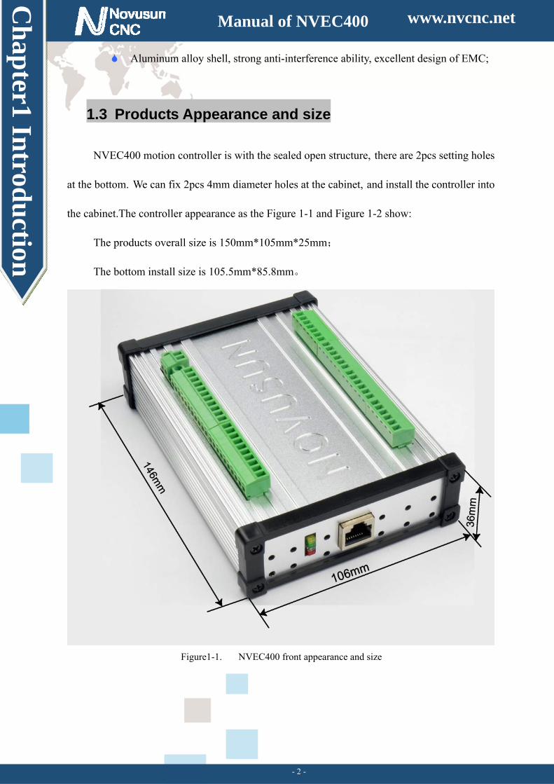
1.3 Products Appearance and size
NVEC400 motion controller is with the sealed open structure, there are 2pcs setting holes
at the bottom. We can fix 2pcs 4mm diameter holes at the cabinet, and install the controller into
the cabinet.The controller appearance as the Figure 1-1 and Figure 1-2 show:
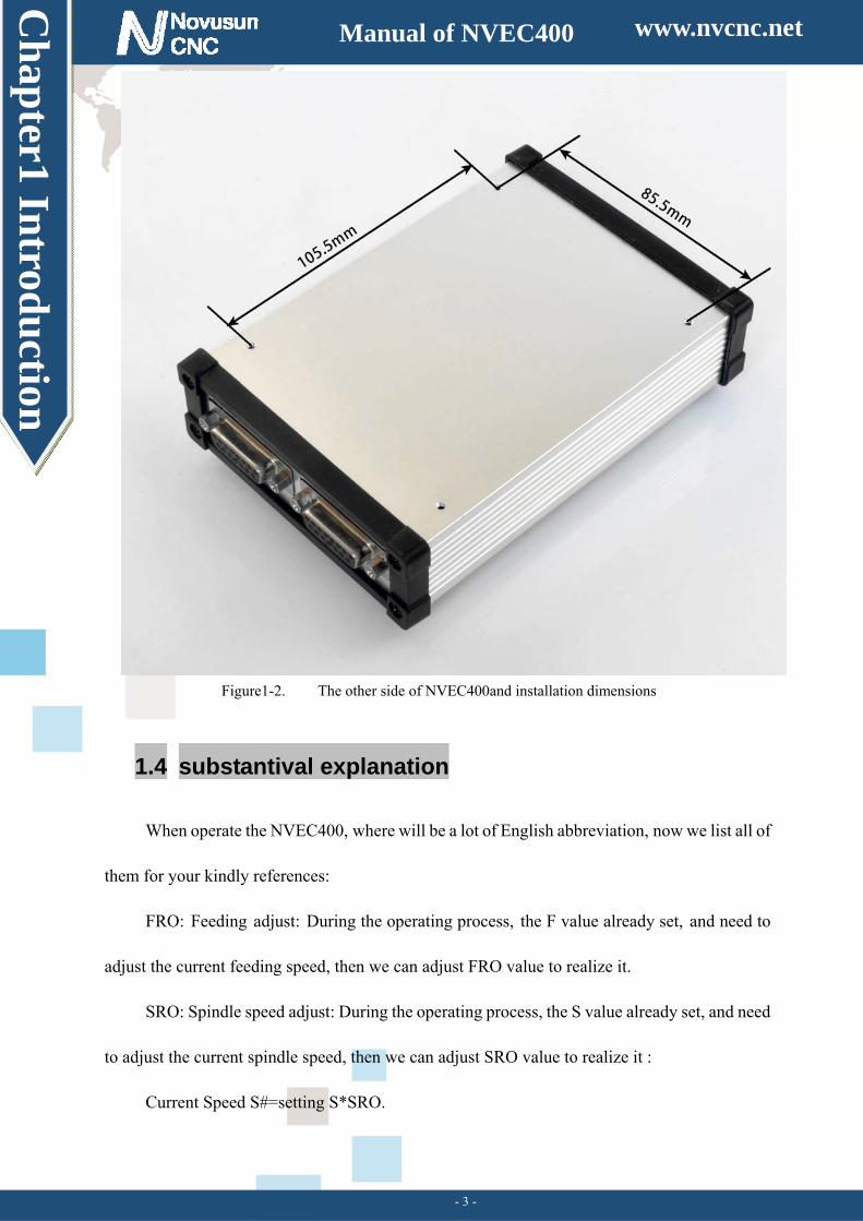
The products overall size is 150mm*105mm*25mm;
The bottom install size is 105.5mm*85.8mm。
Figure1-1. NVEC400 front appearance and size
www.nvcnc.net
Ch
apter1 In
trodu
ction
Manual of NVEC400
- 3 -
Figure1-2. The other side of NVEC400and installation dimensions
1.4 substantival explanation
When operate the NVEC400, where will be a lot of English abbreviation, now we list all of
them for your kindly references:
FRO: Feeding adjust: During the operating process, the F value already set, and need to
adjust the current feeding speed, then we can adjust FRO value to realize it.
SRO: Spindle speed adjust: During the operating process, the S value already set, and need
to adjust the current spindle speed, then we can adjust SRO value to realize it :
Current Speed S#=setting S*SRO.
www.nvcnc.net
Ch
apter1 In
trodu
ction
Manual of NVEC400
- 4 -
SRJ: speed adjust manually
During the operating process,as the manual speed already set,and we need to adjust the
current speed,and impossible to fix the value during it is working,then we can revise the SRJ
value to realize it.
Current manual speed FS#=Setting manual speed*SRJ.
F:Feedingspeed,the unit is mm/min.For example F=200,means every minute feeding
2000mm.
S: Spindle Speed. Unit is rad/min.For example S=20000,means 20000 revolution/Minute.
X axis Coordinate
Y axis Coordinate
Z axis Coordinate
A axis Coordinate
B axis Coordinate
C axis Coordinate
Ready:ReadyMode.In the mode we can do any operation,include processing or values
modification or starting 2nd mode.
Reset: Reset mode.In this mode,it should stop every operation.
“Step”:Manual Step Mode. Every axis candonduct the manual step operation at this mode.
MPG: MPG mode.Every axis can conduct the MPG operation at this mode.
www.nvcnc.net
Ch
apter1 In
trodu
ction
Manual of NVEC400
- 5 -
1.5 Noting and Waring
Free from exposure to the electronics without waterproof
function.Please environment as dry as possible. This is the icon.
Wiring warning, the IO input terminal of this equipment support the
equipment with source switch (such as Inductive proximity switch.)When using
such kind of switch, attention please: avoid the +terminal and –terminal of
power supply to connect with GND.This equipment’s analogy quantity
output terminal of spindlecontrolalos have a certain load capacity. Please avoid
this terminal connect with GND.in case that the interior components and parts be
brokendown.
Operation warning, Please do the security measures well when
connecting with the machine tools.The ESTOP, limit and other things must be
perfected.When comes across the emergancy, please press the ESTOP key at once
or cut off the power directly, thus avoiding the equipment damage and casualty.
High voltage danger, the primary device is 18-32VDC power
supply.Voltage equipment.Pls pay attention to the electricity, safety when conducting
the operation
www.nvcnc.net
Ch
apter2 C
onn
ection
Manual of NVEC400
- 6 -
Chapter 2. Connection
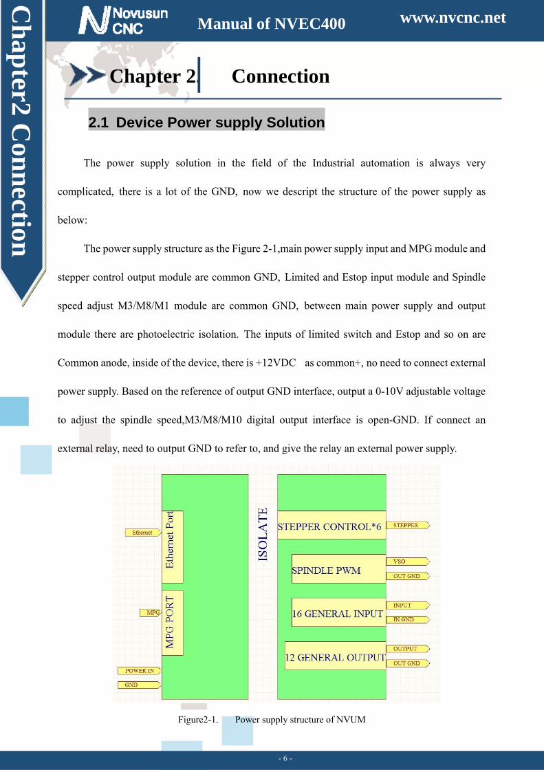
2.1 Device Power supply Solution
The power supply solution in the field of the Industrial automation is always very
complicated, there is a lot of the GND, now we descript the structure of the power supply as
below:
The power supply structure as the Figure 2-1,main power supply input and MPG module and
stepper control output module are common GND, Limited and Estop input module and Spindle
speed adjust M3/M8/M1 module are common GND, between main power supply and output
module there are photoelectric isolation. The inputs of limited switch and Estop and so on are
Common anode, inside of the device, there is +12VDC as common+, no need to connect external
power supply. Based on the reference of output GND interface, output a 0-10V adjustable voltage
to adjust the spindle speed,M3/M8/M10 digital output interface is open-GND. If connect an
external relay, need to output GND to refer to, and give the relay an external power supply.
Figure2-1. Power supply structure of NVUM
www.nvcnc.net
Ch
apter2 C
onn
ection
Manual of NVEC400
- 7 -
2.2 Product connection define and method
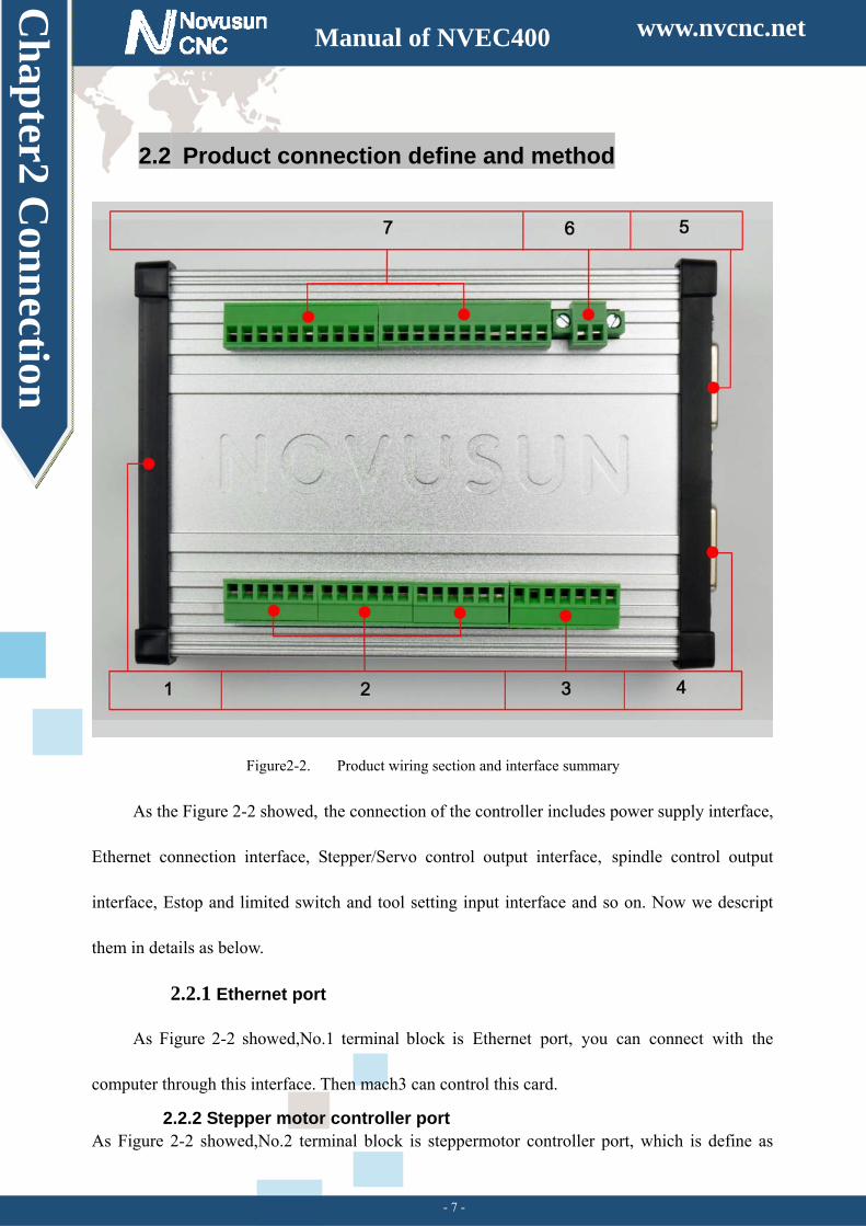
Figure2-2. Product wiring section and interface summary
As the Figure 2-2 showed, the connection of the controller includes power supply interface,
Ethernet connection interface, Stepper/Servo control output interface, spindle control output
interface, Estop and limited switch and tool setting input interface and so on. Now we descript
them in details as below.
2.2.1 Ethernet port
As Figure 2-2 showed,No.1 terminal block is Ethernet port, you can connect with the
computer through this interface. Then mach3 can control this card.
2.2.2 Stepper motor controller port As Figure 2-2 showed,No.2 terminal block is steppermotor controller port, which is define as
www.nvcnc.net
Ch
apter2 C
onn
ection
Manual of NVEC400
- 8 -
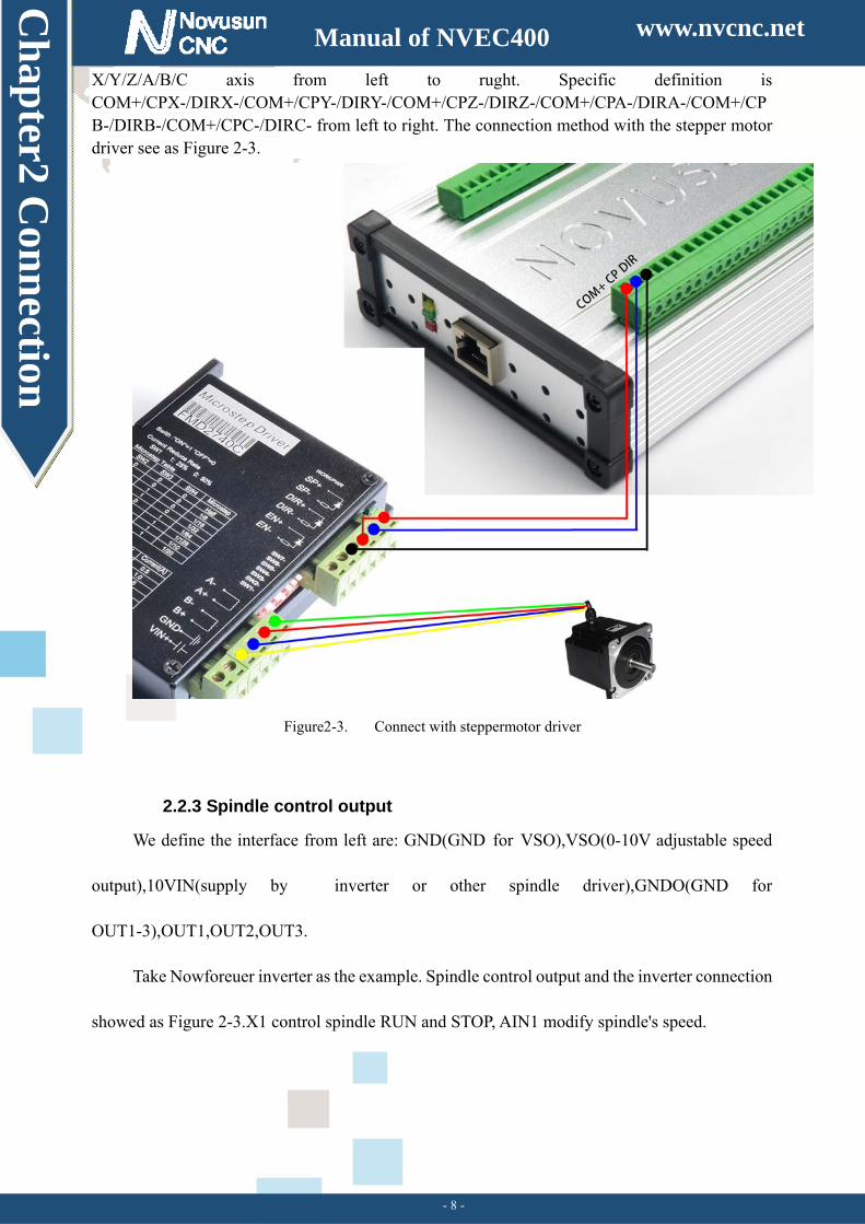
X/Y/Z/A/B/C axis from left to rught. Specific definition is COM+/CPX-/DIRX-/COM+/CPY-/DIRY-/COM+/CPZ-/DIRZ-/COM+/CPA-/DIRA-/COM+/CPB-/DIRB-/COM+/CPC-/DIRC- from left to right. The connection method with the stepper motor driver see as Figure 2-3.
Figure2-3. Connect with steppermotor driver
2.2.3 Spindle control output
We define the interface from left are: GND(GND for VSO),VSO(0-10V adjustable speed
output),10VIN(supply by inverter or other spindle driver),GNDO(GND for
OUT1-3),OUT1,OUT2,OUT3.
Take Nowforeuer inverter as the example. Spindle control output and the inverter connection
showed as Figure 2-3.X1 control spindle RUN and STOP, AIN1 modify spindle's speed.
www.nvcnc.net
Ch
apter2 C
onn
ection
Manual of NVEC400
- 9 -
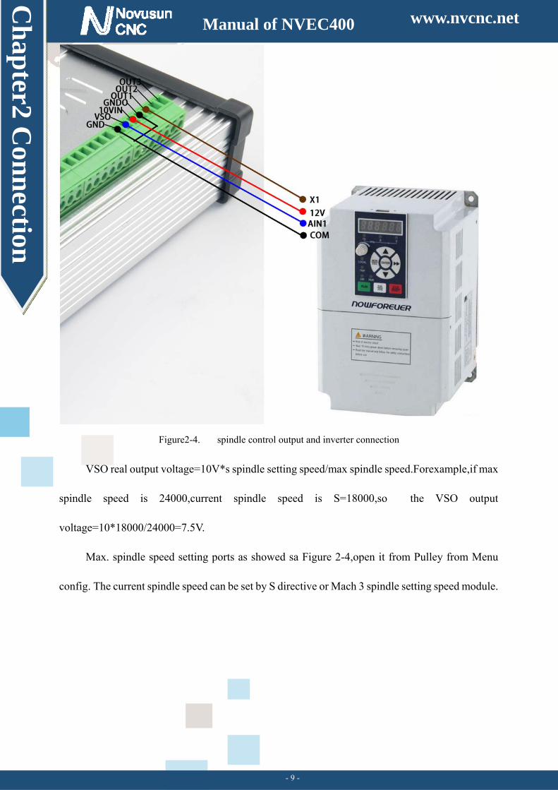
Figure2-4. spindle control output and inverter connection
VSO real output voltage=10V*s spindle setting speed/max spindle speed.Forexample,if max
spindle speed is 24000,current spindle speed is S=18000,so the VSO output
voltage=10*18000/24000=7.5V.
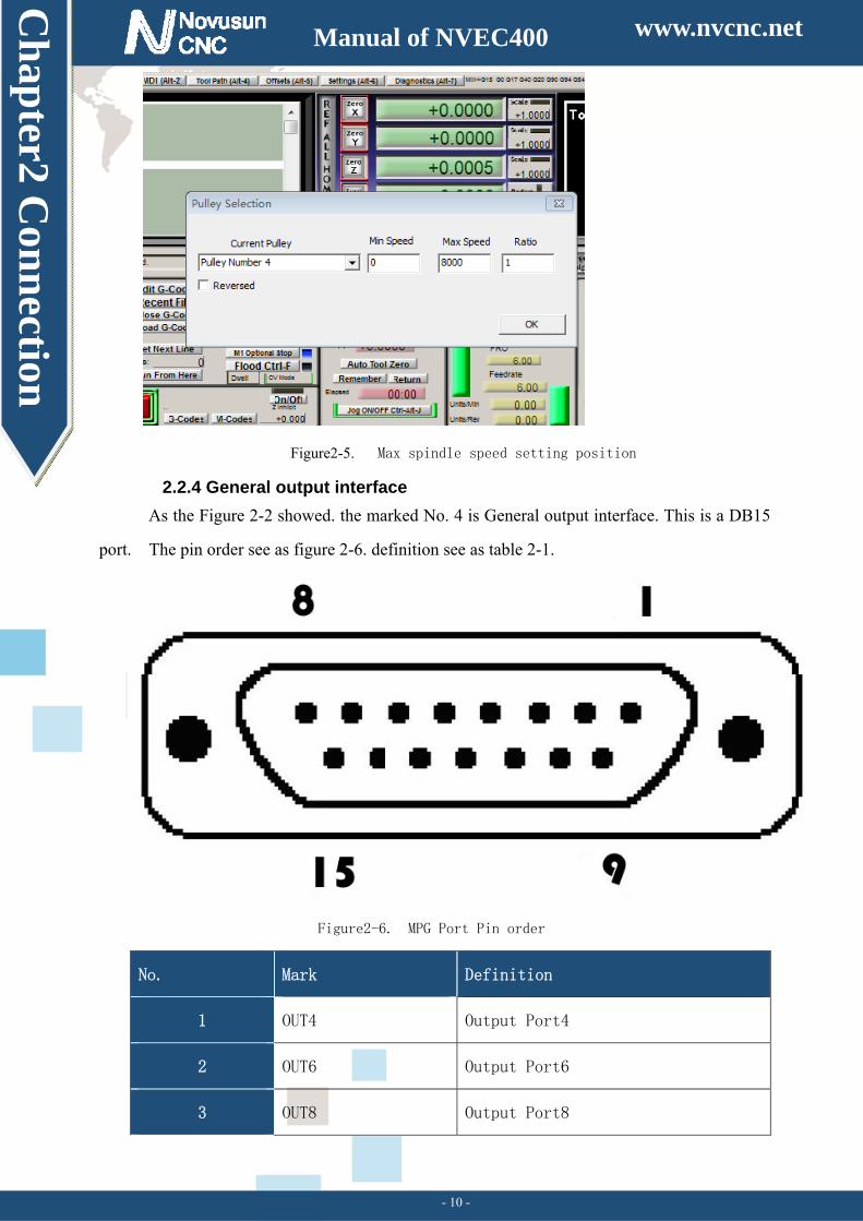
Max. spindle speed setting ports as showed sa Figure 2-4,open it from Pulley from Menu
config. The current spindle speed can be set by S directive or Mach 3 spindle setting speed module.
www.nvcnc.net
Ch
apter2 C
onn
ection
Manual of NVEC400
- 10 -
Figure2-5. Max spindle speed setting position
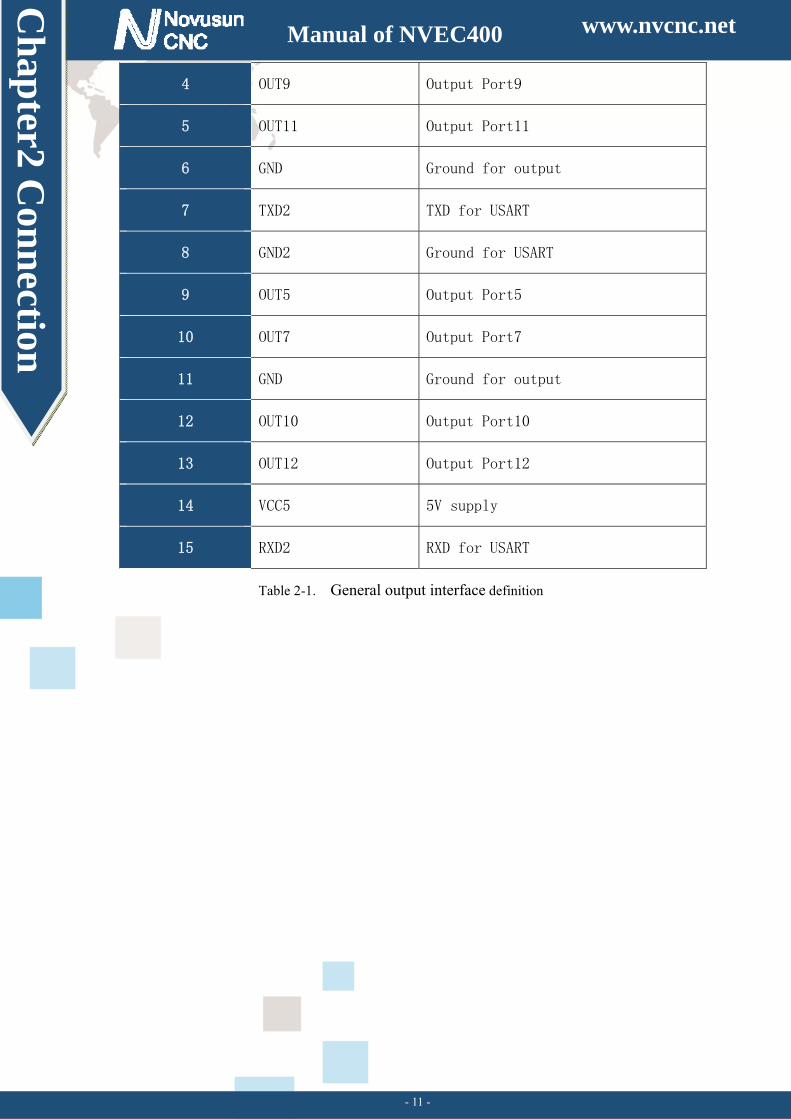
2.2.4 General output interface
As the Figure 2-2 showed. the marked No. 4 is General output interface. This is a DB15
port. The pin order see as figure 2-6. definition see as table 2-1.
Figure2-6. MPG Port Pin order
No. Mark Definition
1 OUT4 Output Port4
2 OUT6 Output Port6
3 OUT8 Output Port8
www.nvcnc.net
Ch
apter2 C
onn
ection
Manual of NVEC400
- 11 -
4 OUT9 Output Port9
5 OUT11 Output Port11
6 GND Ground for output
7 TXD2 TXD for USART
8 GND2 Ground for USART
9 OUT5 Output Port5
10 OUT7 Output Port7
11 GND Ground for output
12 OUT10 Output Port10
13 OUT12 Output Port12
14 VCC5 5V supply
15 RXD2 RXD for USART
Table 2-1. General output interface definition
www.nvcnc.net
Ch
apter2 C
onn
ection
Manual of NVEC400
- 12 -
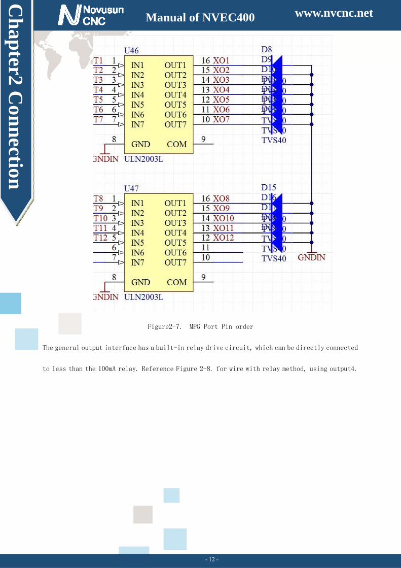
Figure2-7. MPG Port Pin order
The general output interface has a built-in relay drive circuit, which can be directly connected
to less than the 100mA relay. Reference Figure 2-8. for wire with relay method, using output4.
www.nvcnc.net
Ch
apter2 C
onn
ection
Manual of NVEC400
- 13 -
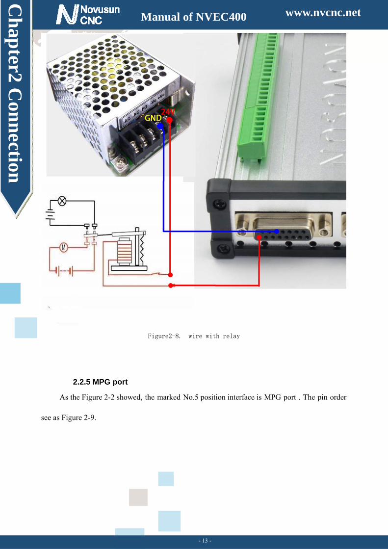
Figure2-8. wire with relay
2.2.5 MPG port
As the Figure 2-2 showed, the marked No.5 position interface is MPG port . The pin order
see as Figure 2-9.
www.nvcnc.net
Ch
apter2 C
onn
ection
Manual of NVEC400
- 14 -
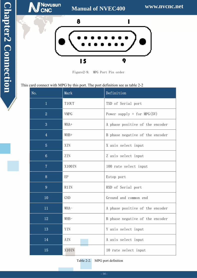
Figure2-9. MPG Port Pin order
This card connect with MPG by this port. The port definition see as table 2-2
No. Mark Definition
1 T1OUT TXD of Serial port
2 VMPG Power supply + for MPG(5V)
3 WHA+ A phase positive of the encoder
4 WHB+ B phase negative of the encoder
5 XIN X axis select input
6 ZIN Z axis select input
7 X100IN 100 rate select input
8 EP Estop port
9 R1IN RXD of Serial port
10 GND Ground and common end
11 WHA- A phase positive of the encoder
12 WHB- B phase negative of the encoder
13 YIN Y axis select input
14 AIN A axis select input
15 X10IN 10 rate select input
Table 2-2. MPG port definition
www.nvcnc.net
Ch
apter2 C
onn
ection
Manual of NVEC400
- 15 -
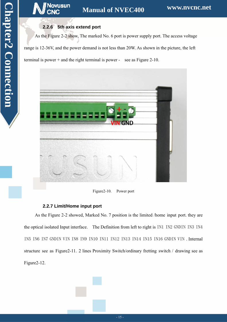
2.2.6 5th axis extend port
As the Figure 2-2 show, The marked No. 6 port is power supply port. The access voltage
range is 12-36V, and the power demand is not less than 20W. As shown in the picture, the left
terminal is power + and the right terminal is power - see as Figure 2-10.
Figure2-10. Power port
2.2.7 Limit/Home input port
As the Figure 2-2 showed, Marked No. 7 position is the limited /home input port. they are
the optical isolated Input interface. The Definition from left to right is IN1 IN2 GNDIN IN3 IN4
IN5 IN6 IN7 GNDIN VIN IN8 IN9 IN10 IN11 IN12 IN13 IN14 IN15 IN16 GNDIN VIN . Internal
structure see as Figure2-11. 2 lines Proximity Switch/ordinary fretting switch / drawing see as
Figure2-12.
www.nvcnc.net
Ch
apter2 C
onn
ection
Manual of NVEC400
- 16 -
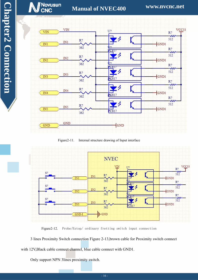
Figure2-11. Internal structure drawing of Input interface
Figure2-12. Probe/Estop/ ordinary fretting switch input connection
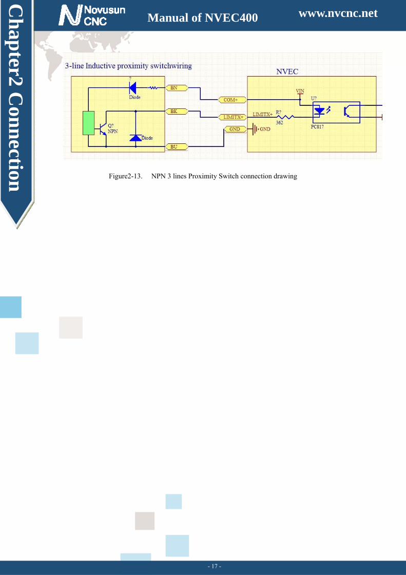
3 lines Proximity Switch connection Figure 2-13,brown cable for Proximity switch connect
with 12V,Black cable connect channel, blue cable connect with GND1.
Only support NPN 3lines proximity switch.
www.nvcnc.net
Ch
apter2 C
onn
ection
Manual of NVEC400
- 17 -
Figure2-13. NPN 3 lines Proximity Switch connection drawing
www.nvcnc.net
Ch
apter3 S
oftware In
stallation
Manual of USB8727T4
- 18 -
Chapter 3. Software Installation
3.1 MACH3 Install
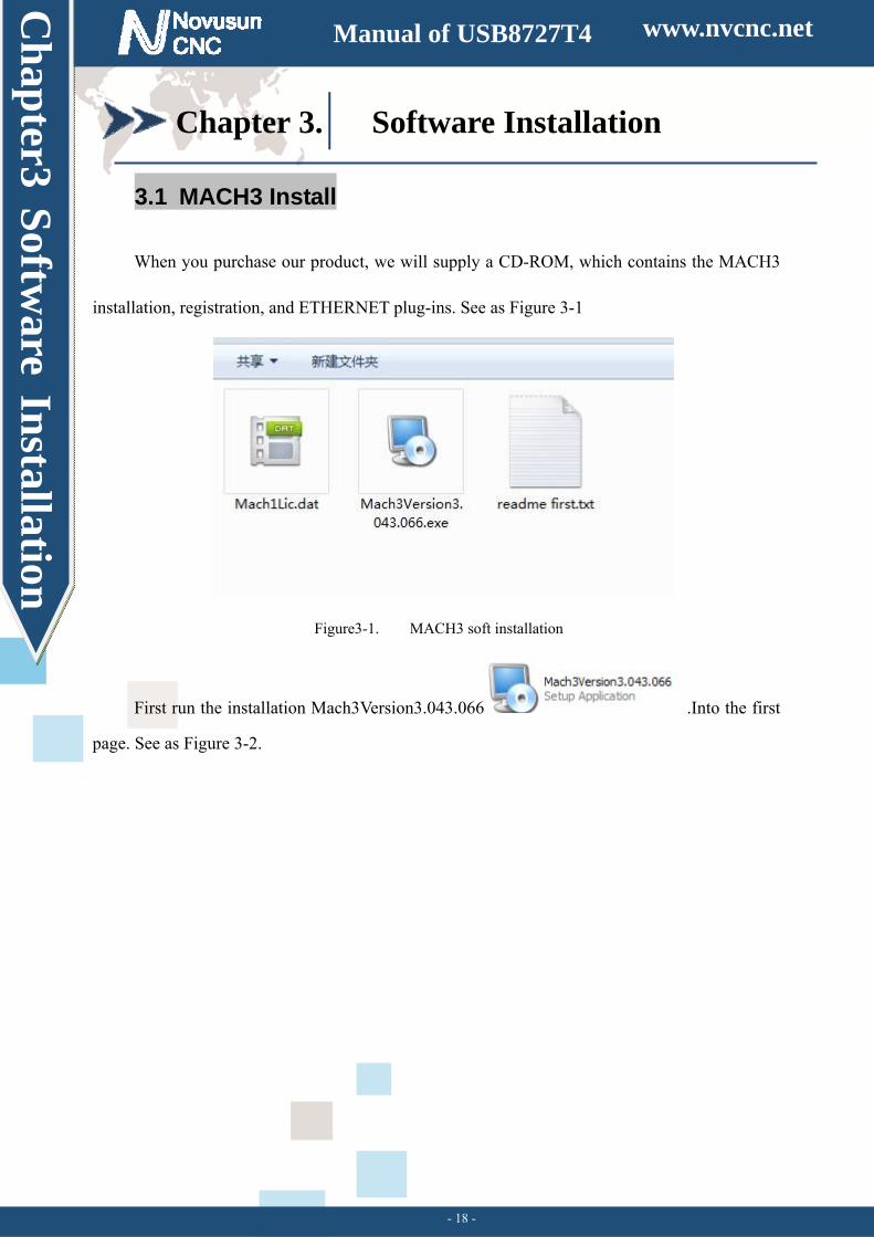
When you purchase our product, we will supply a CD-ROM, which contains the MACH3
installation, registration, and ETHERNET plug-ins. See as Figure 3-1
Figure3-1. MACH3 soft installation
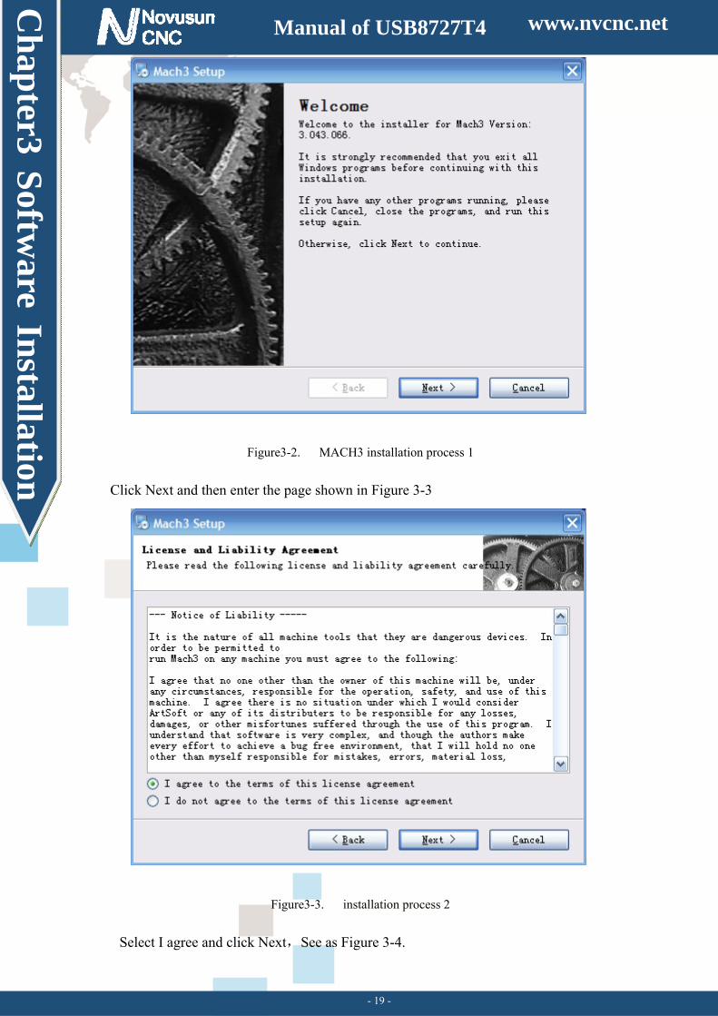
First run the installation Mach3Version3.043.066 .Into the first
page. See as Figure 3-2.
www.nvcnc.net
Ch
apter3 S
oftware In
stallation
Manual of USB8727T4
- 19 -
Figure3-2. MACH3 installation process 1
Click Next and then enter the page shown in Figure 3-3
Figure3-3. installation process 2
Select I agree and click Next,See as Figure 3-4.
www.nvcnc.net
Ch
apter3 S
oftware In
stallation
Manual of USB8727T4
- 20 -
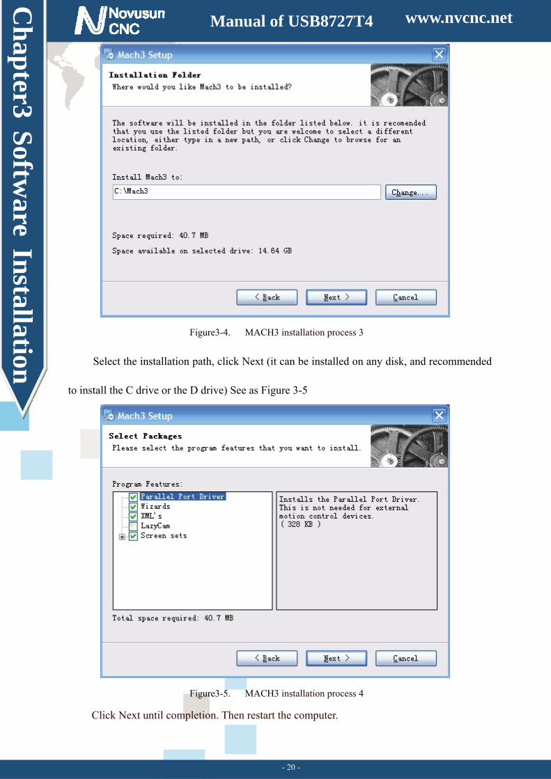
Figure3-4. MACH3 installation process 3
Select the installation path, click Next (it can be installed on any disk, and recommended
to install the C drive or the D drive) See as Figure 3-5
Figure3-5. MACH3 installation process 4
Click Next until completion. Then restart the computer.
www.nvcnc.net
Ch
apter3 S
oftware In
stallation
Manual of USB8727T4
- 21 -
3.2 Plugin Install
Copy the file NOVUSUN.DLL to X:/mach3/plugin, X is installation disk of
mach3.
www.nvcnc.net
Ch
apter4 S
etting of softw
are
Manual of NVEC400
- 22 -
Chapter 4. Setting of software
4.1 Open software
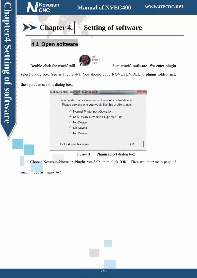
Double-click the mach3mill . Start mach3 software. We enter plugin
select dialog box. See as Figure 4-1. You should copy NOVUSUN.DLL to plguin folder first,
then you can see this dialog box.
Figure4-1. Plguin select dialog box
Choose Novusun-Novusun-Plugin_ver-3.0b, then click "OK". Then we enter main page of
mach3. See as Figure 4-2.
www.nvcnc.net
Ch
apter4 S
etting of softw
are
Manual of NVEC400
- 23 -
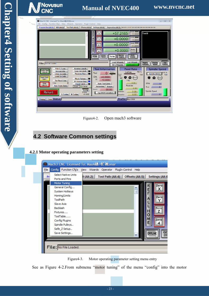
Figure4-2. Open mach3 software
4.2 Software Common settings
4.2.1 Motor operating parameters setting
Figure4-3. Motor operating parameter setting menu entry
See as Figure 4-2.From submenu “motor tuning” of the menu “config” into the motor
www.nvcnc.net
Ch
apter4 S
etting of softw
are
Manual of NVEC400
- 24 -
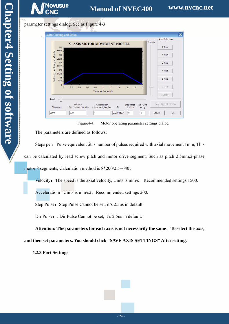
parameter settings dialog. See as Figure 4-3
Figure4-4. Motor operating parameter settings dialog
The parameters are defined as follows:
S :teps per Pulse equivalent ,it is number of pulses required with axial movement 1mm, This
can be calculated by lead screw pitch and motor drive segment. Such as pitch 2.5mm,2-phase
motor 8 segments, Calculation method is 。8*200/2.5=640
:Velocity The speed is the axial velocity, Units ,is mm/s Recommended settings 1500.
:Acceleration Units ,is mm/s2 Recommended settings 200.
:Step Pulse Step Pulse Cannot be set, it’s 2.5us in default.
:Dir Pulse . Dir Pulse Cannot be set, it’s 2.5us in default.
Attention: The parameters for each axis is not necessarily the same,To select the axis,
and then set parameters. You should click “SAVE AXIS SETTINGS” After setting.
4.2.3 Port Settings
www.nvcnc.net
Ch
apter4 S
etting of softw
are
Manual of NVEC400
- 25 -
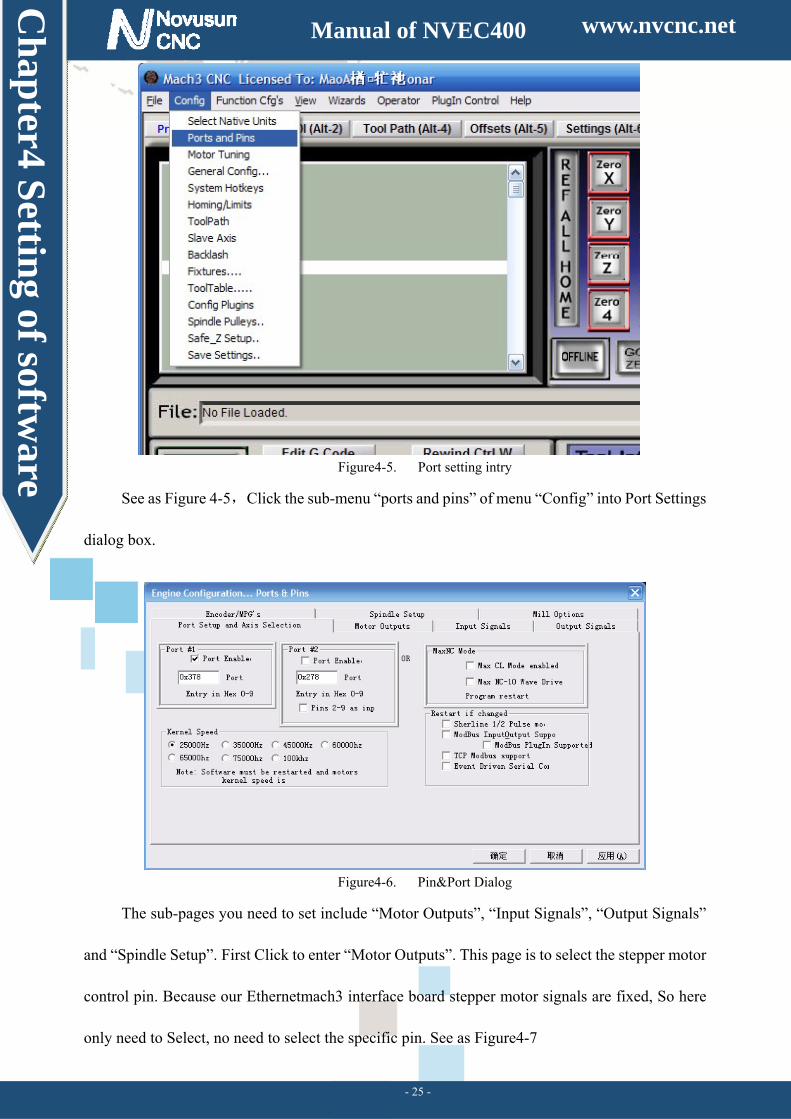
Figure4-5. Port setting intry
See as Figure 4-5,Click the sub-menu “ports and pins” of menu “Config” into Port Settings
dialog box.
Figure4-6. Pin&Port Dialog
The sub-pages you need to set include “Motor Outputs”, “Input Signals”, “Output Signals”
and “Spindle Setup”. First Click to enter “Motor Outputs”. This page is to select the stepper motor
control pin. Because our Ethernetmach3 interface board stepper motor signals are fixed, So here
only need to Select, no need to select the specific pin. See as Figure4-7
www.nvcnc.net
Ch
apter4 S
etting of softw
are
Manual of NVEC400
- 26 -
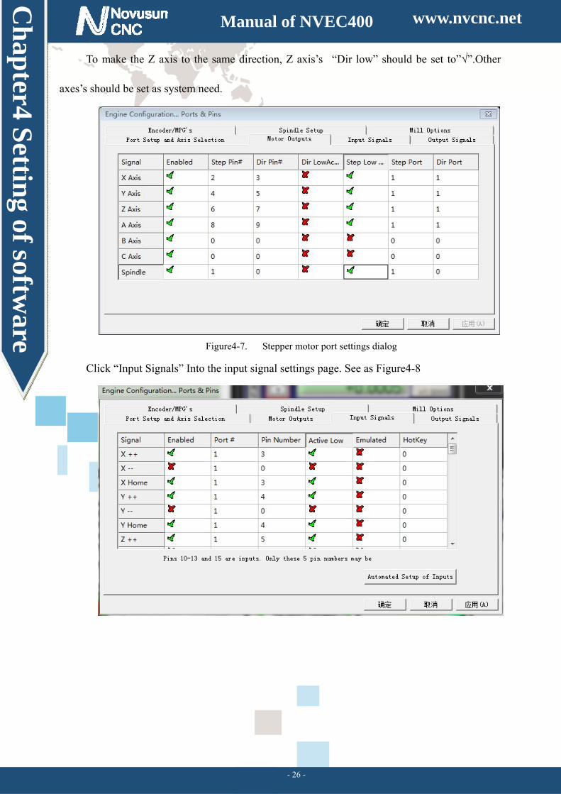
To make the Z axis to the same direction, Z axis’s “Dir low” should be set to”√”.Other
axes’s should be set as system need.
Figure4-7. Stepper motor port settings dialog
Click “Input Signals” Into the input signal settings page. See as Figure4-8
www.nvcnc.net
Ch
apter4 S
etting of softw
are
Manual of NVEC400
- 27 -
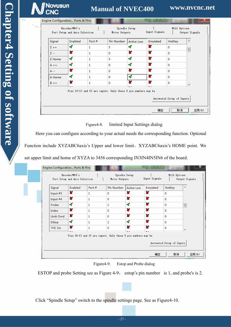
Figure4-8. limited Input Settings dialog
Here you can configure according to your actual needs the corresponding function. Optional
Function include XYZABC6axis’s Upper and lower limit、XYZABC6axis’s HOME point. We
set upper limit and home of XYZA to 3456 corresponding IN3IN4IN5IN6 of the board.
Figure4-9. Estop and Probe dialog
ESTOP and probe Setting see as Figure 4-9, estop’s pin number is 1, and probe's is 2.
Click “Spindle Setup” switch to the spindle settings page. See as Figure4-10.
www.nvcnc.net
Ch
apter4 S
etting of softw
are
Manual of NVEC400
- 28 -
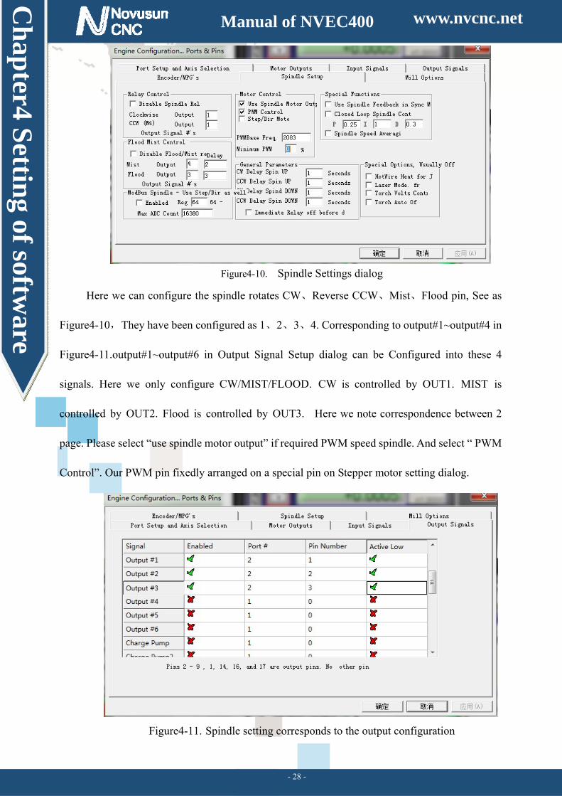
Figure4-10. Spindle Settings dialog
Here we can configure the spindle rotates 、CW Reverse 、 、CCW Mist Flood pin, See as
Figure4-10,They have been configured 、 、 、as 1 2 3 4. Corresponding to output#1~output#4 in
Figure4-11.output#1~output#6 in Output Signal Setup dialog can be Configured into these 4
signals. Here we only configure CW/MIST/FLOOD. CW is controlled by OUT1. MIST is
controlled by OUT2. Flood is controlled by OUT3. Here we note correspondence between 2
page. Please select “use spindle motor output” if required PWM speed spindle. And select “ PWM
Control”. Our PWM pin fixedly arranged on a special pin on Stepper motor setting dialog.
Figure4-11. Spindle setting corresponds to the output configuration
www.nvcnc.net
Ch
apter4 S
etting of softw
are
Manual of NVEC400
- 29 -
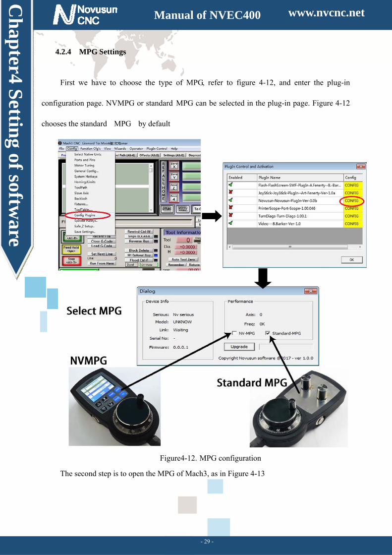
4.2.4 MPG Settings
First we have to choose the type of MPG, refer to figure 4-12, and enter the plug-in
configuration page. NVMPG or standard MPG can be selected in the plug-in page. Figure 4-12
chooses the standard MPG by default
Figure4-12. MPG configuration
The second step is to open the MPG of Mach3, as in Figure 4-13
www.nvcnc.net
Ch
apter4 S
etting of softw
are
Manual of NVEC400
- 30 -
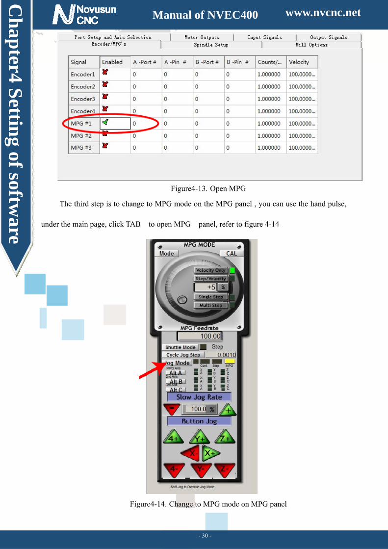
Figure4-13. Open MPG
The third step is to change to MPG mode on the MPG panel , you can use the hand pulse,
under the main page, click TAB to open MPG panel, refer to figure 4-14
Figure4-14. Change to MPG mode on MPG panel
www.nvcnc.net
Ch
apter5 U
sing of softw
are
Manual of NVEC400
- 31 -
Chapter 5. Using of software
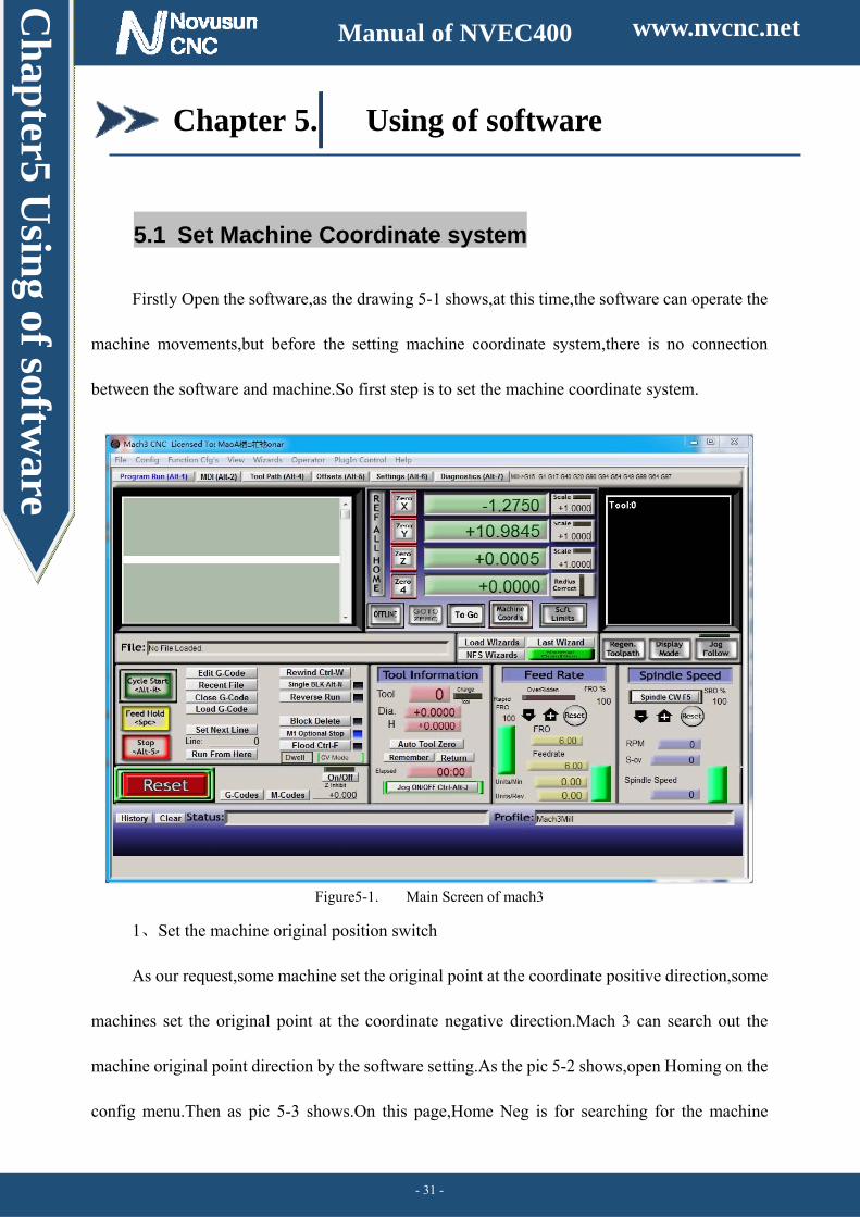
5.1 Set Machine Coordinate system
Firstly Open the software,as the drawing 5-1 shows,at this time,the software can operate the
machine movements,but before the setting machine coordinate system,there is no connection
between the software and machine.So first step is to set the machine coordinate system.
Figure5-1. Main Screen of mach3
、1 Set the machine original position switch
As our request,some machine set the original point at the coordinate positive direction,some
machines set the original point at the coordinate negative direction.Mach 3 can search out the
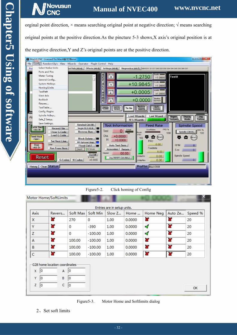
machine original point direction by the software setting.As the pic 5-2 shows,open Homing on the
config menu.Then as pic 5-3 shows.On this page,Home Neg is for searching for the machine
www.nvcnc.net
Ch
apter5 U
sing of softw
are
Manual of NVEC400
- 32 -
orginal point direction, × means searching original point at negative direction; √ means searching
original points at the positive direction.As the pincture 5-3 shows,X axis’s original position is at
the negative direction,Y and Z’s original points are at the positive direction.
Figure5-2. Click homing of Config
Figure5-3. Motor Home and Softlimits dialog
、2 Set soft limits
www.nvcnc.net
Ch
apter5 U
sing of softw
are
Manual of NVEC400
- 33 -
As Figure 5-3 shows,this page also can set machine soft limit points,Soft Max is positive
direction soft limited points,soft Min is negative direction soft limited points.The soft limited
points values is according the references to the machine coordinate system,so as this example
shows,Y and Z axis’s max value is 0,all the effective coordinate data is less than 0.As the Figure
shows,according to our current request,we set our XYZ axis soft limited points area as [0,270]
[-390,0] [-100,0].
、3 Searching for machine original points
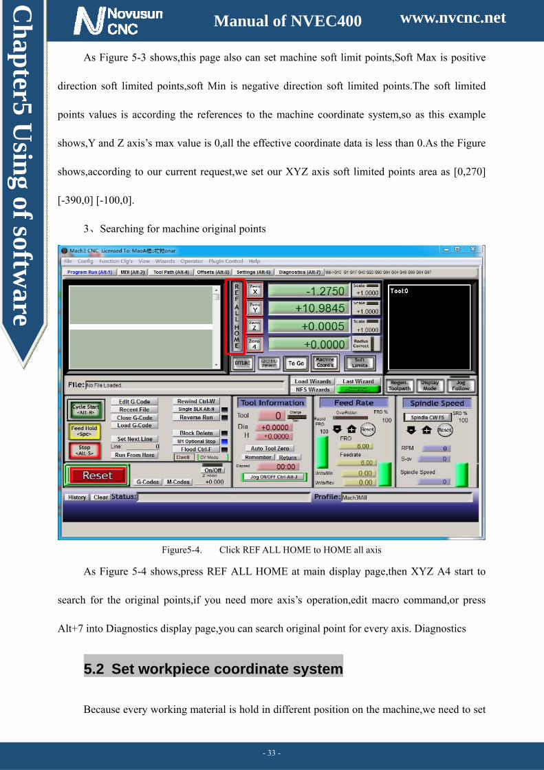
Figure5-4. Click REF ALL HOME to HOME all axis
As Figure 5-4 shows,press REF ALL HOME at main display page,then XYZ A4 start to
search for the original points,if you need more axis’s operation,edit macro command,or press
Alt+7 into Diagnostics display page,you can search original point for every axis. Diagnostics
5.2 Set workpiece coordinate system
Because every working material is hold in different position on the machine,we need to set
www.nvcnc.net
Ch
apter5 U
sing of softw
are
Manual of NVEC400
- 34 -
one or more workpiece coordinate system.
、1 Move to current working piece 0 point
Firstly hold down the material,use keyboard or pendant to move tool tip at the 0 point,so this
0 point is the working piece 0 point,it related with the working G code file,so the user must be very
familiar to his own working G code.As our example shows,the 0 point is on the center of the
working piece surface,so we just move the tool tip to this position.
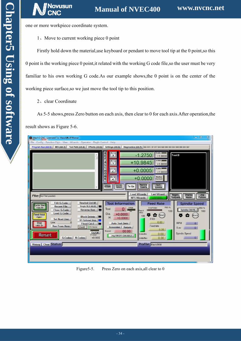
、2 clear Coordinate
As 5-5 shows,press Zero button on each axis, then clear to 0 for each axis.After operation,the
result shows as Figure 5-6.
Figure5-5. Press Zero on each axis,all clear to 0
www.nvcnc.net
Ch
apter5 U
sing of softw
are
Manual of NVEC400
- 35 -
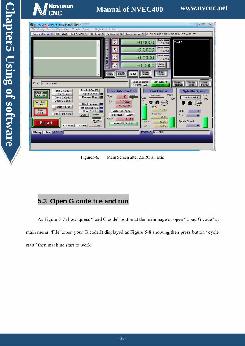
Figure5-6. Main Screen after ZERO all axis
5.3 Open G code file and run
As Figure 5-7 shows,press “load G code” botton at the main page or open “Load G code” at
main menu “File”,open your G code.It displayed as Figure 5-8 showing,then press button “cycle
start” then machine start to work.
www.nvcnc.net

Ch
apter5 U
sing of softw
are
Manual of NVEC400
- 36 -
Figure5-7. Press Load G-Code and open your G code
Figure5-8. After opening G code,press “Cycle Start” and start to work
www.nvcnc.net
www.nvcnc.com
Ch
apter7 C
ontract u
s
Manual of NVEC400
- 38 -
Chapter 7. Contract us
Website:WWW.NVCNC.COM
Support Email:[email protected]


![Servo Motion Controller Basics(Hardware) ENG.ppt [互換モード] · .X-Y table Motion program The application examples of the motion control are introduced in the following. Click](https://static.fdocument.pub/doc/165x107/5d00aa4188c99363028ba1d9/servo-motion-controller-basicshardware-engppt-x-y-table.jpg)