
Low temperature ionothermal synthesis of LiFeSO4F...
15
Low temperature ionothermal synthesis of LiFeSO 4 F cathode material for lithium-ion battery 1 Kuang-Che Hsiao Supervisor: Prof. Tony West 23/03/2010 1 E-Futures DTC, Department of Engineering Materials, The University of Sheffield, UK Phone: +44(0)7506363514; E-mail: [email protected]
-
Upload
trinhkhanh -
Category
Documents
-
view
215 -
download
0
Transcript of Low temperature ionothermal synthesis of LiFeSO4F...
Low temperature ionothermal synthesis of LiFeSO4F cathode material for lithium-ion battery
1
Kuang-Che Hsiao
Supervisor: Prof. Tony West
23/03/2010
1
E-Futures DTC, Department of Engineering Materials, The University of Sheffield, UK
Phone: +44(0)7506363514; E-mail: [email protected]

2
Outline Background Introduction
- Material (LiFeSO4F)- Methodology (Ionothermal)
Experimental procedure Results and discussion ConclusionsAcknowledgements

3
History.........LiFeSO4F (2009-2010)
Source: NATURE MATERIALS VOL 9 JANUARY 2010.
Jean-Marie Tarascon
Michel Armand
Laboratory of Reactivity and Chemistry of Solids, University of Picardie Jules Verne, France
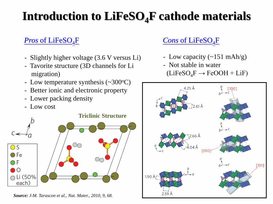
- Slightly higher voltage (3.6 V versus Li) - Tavorite structure (3D channels for Li
migration)- Low temperature synthesis (~300oC)- Better ionic and electronic property - Lower packing density - Low cost
- Low capacity (~151 mAh/g)- Not stable in water (LiFeSO4F → FeOOH + LiF)
Pros of LiFeSO4F
4
Cons of LiFeSO4F
Introduction to LiFeSO4F cathode materials
Triclinic Structure
Source: J-M. Tarascon et al., Nat. Mater., 2010, 9, 68.

demonstrated the relation between electricity and chemical bonding,
Capacity (mAh/g) = [ ( F × nLi ) / ( M × 3600 ) ] × 1000Where, F = Faraday’s constant ( 96,500 coulombs per gm equivalent)
nLi = Number of Li per formula unit of the electrode materialM = Molecular mass of the electrode material
Charles-Augustin de Coulomb(1736-1806), France
Michael Faraday (1791-1867), England
gmAhFLiFeSO
FFeSOLieFLiFeSOCathode
/1511000360085.177
196500
:
4
44
=×××
=
+→+ −
5
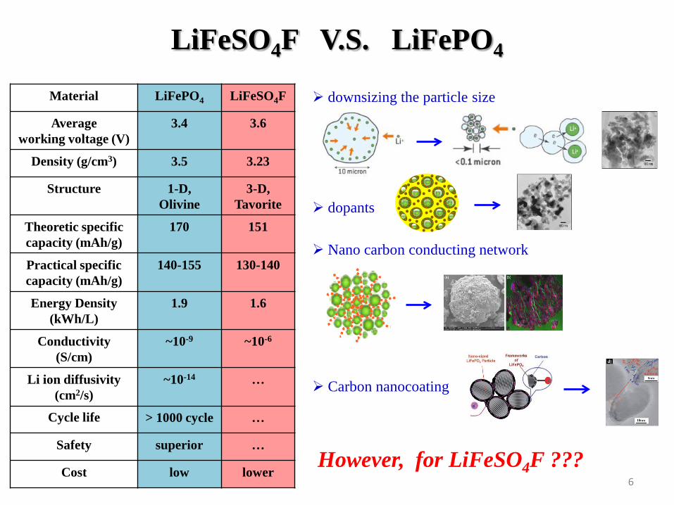
LiFeSO4F V.S. LiFePO4
Material LiFePO4 LiFeSO4F
Average working voltage (V)
3.4 3.6
Density (g/cm3) 3.5 3.23
Structure 1-D,Olivine
3-D,Tavorite
Theoretic specific capacity (mAh/g)
170 151
Practical specific capacity (mAh/g)
140-155 130-140
Energy Density (kWh/L)
1.9 1.6
Conductivity(S/cm)
~10-9 ~10-6
Li ion diffusivity (cm2/s)
~10-14 …
Cycle life > 1000 cycle …
Safety superior …
Cost low lower
downsizing the particle size
dopants
Nano carbon conducting network
Carbon nanocoating
However, for LiFeSO4F ???6

Summary of synthesis approaches toward the electrode materials
7
The experiment were carried out at 250 °C inglassware containers using EMI-TFSI as ionicliquid and LiH2PO4, FeC2O4 ·2H2O precursorswith concentration of 2.5 × 10⁻³ mol/L.
Ionothermal Synthesis for LiFePO4
Source: N. Recham et al.,Chem. Mater. 2009, 21, 1096.Source: Jean-Marie Tarascon et al., Chem. Mater. 2010, 22(3), 724.

8
Ionic liquid: 1-ethyl-3-methylimidazolium bis-(trifluoromethanesulfonyl) imide (EMI-TFSI)
Properties and applications of ionic-liquids Role of the ionic liquid
TGA measurements conducted in the presence of eitherFeSO4 . H2O + ionic liquid, or FeSO4 . H2O + ionicliquid + LiF are compared to those done with onlyionic liquid or FeSO4 . H2O. Note that EMI-TFSIpostpones the release of H2O until temperatures greaterthan 280°C, temperatures at which the double ionexchange reaction (H+ for Li+ and OH− for F−) canproceed leading to the formation of LiFeSO4F.
Source: Jean-Marie Tarascon et al., Chem. Mater. 2010, 22(3), 724.
Source: Michel Armand et al., Nat. Mater., 2009, 8, 621.
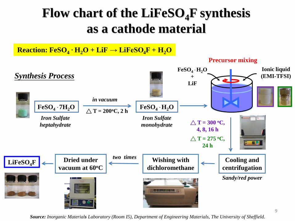
Flow chart of the LiFeSO4F synthesis as a cathode material
Reaction: FeSO4. H2O + LiF → LiFeSO4F + H2O
Synthesis Process
FeSO4 . 7H2Oin vacuum
△ T = 200oC, 2 h FeSO4 . H2OIron Sulfateheptahydrate △ T = 300 oC,
4, 8, 16 h
Cooling and centrifugation
Wishing with dichloromethane
two timesDried under vacuum at 60oC
LiFeSO4F
Sandy/red power
△ T = 275 oC, 24 h
Source: Inorganic Materials Laboratory (Room I5), Department of Engineering Materials, The University of Sheffield.
Precursor mixingIonic liquid (EMI-TFSI)
FeSO4 . H2O +
LiF
9
Iron Sulfatemonohydrate
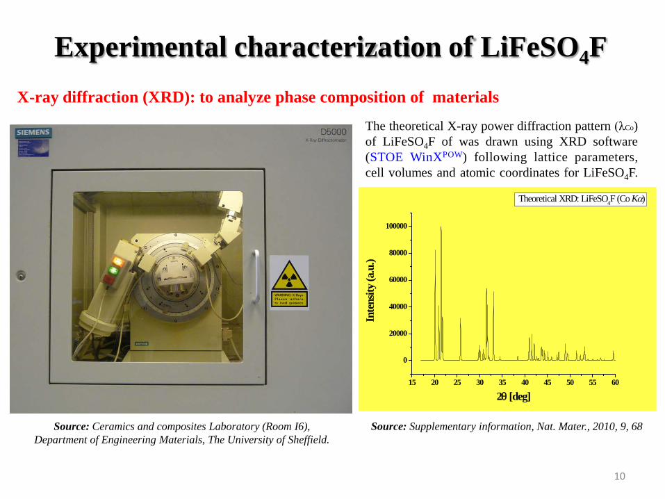
Experimental characterization of LiFeSO4F X-ray diffraction (XRD): to analyze phase composition of materials
15 20 25 30 35 40 45 50 55 60
0
20000
40000
60000
80000
100000
Inte
nsity
(a.u
.)
2θ [deg]
Theoretical XRD: LiFeSO4F (Co Kα)
Source: Ceramics and composites Laboratory (Room I6), Department of Engineering Materials, The University of Sheffield.
The theoretical X-ray power diffraction pattern (λCo)of LiFeSO4F of was drawn using XRD software(STOE WinXPOW) following lattice parameters,cell volumes and atomic coordinates for LiFeSO4F.
Source: Supplementary information, Nat. Mater., 2010, 9, 68
10
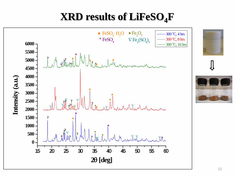
XRD results of LiFeSO4F
15 20 25 30 35 40 45 50 55 60
0500
10001500200025003000350040004500500055006000
∇
•♦♦
♦∇*∇ ?????
?
????
??
??
?
???
∇ Fe2(SO4)3
∇
∇
∇
∇∇∇
∇ ∇ ∇∇∇
• Fe2O3
••
* FeSO4
*
**
*
♦ FeSO4⋅ H2O
♦
♦ ♦
♦♦
♦
♦
Inte
nsity
(a.u
.)
2θ [deg]
300 oC, 4 hrs 300 oC, 8 hrs 300 oC, 16 hrs
*
•
∇
?
11

XRD results of LiFeSO4F
15 20 25 30 35 40 45 50 55 60
0
1000
2000
3000
4000
5000
6000
∇
∇∇•?
?♦
•
•
♦
♦
♦
??
?
?
?∇∇♦
???
?∇∇
*?
Inte
nsity
(a.u
.)
2θ [deg]
275 oC, 24 hrs 280 oC, 48 hrs∇ Fe2(SO4)3
• Fe2O3
* FeSO4
♦ FeSO4⋅ H2O
12

XRD discussion of LiFeSO4F
Latent difficulties to synthesize single phase LiFeSO4F:1. The reaction paths of ionothermal synthesis and mechanism of ion-exchange for phase stabilization of
LiFeSO4F is hard to understand because of experimental temperature, pressure, composition and reaction time.2. Too many Li+ perhaps solve into ionic liquid due to the existence of FeSO4 . H2O phase in produced material . 3. It is difficult to keep the monohydrated precursor free of Fe(III) ( Iron oxidation: Fe2+ → Fe3+ )
0 4 8 12 16 20 24 28 32 36 40 44 48 52
275
280
285
290
295
300
X∇•♦
X
∇•♦XX∇•
♦
♦∇•
*
X *
•
*
∇
♦
LiFeSO4F ♦ FeSO4⋅ H2O * FeSO4
• Fe2O3
∇ Fe2(SO4)3
X unknown
Tem
pera
ture
(o C)
Reaction time (hrs)
Pressure (Pa)
13

Conclusions
The ionothermal synthesis of LiFeSO4F cathode is quite straightforward. However, more studies need to be done to understand thermodynamic and kinetic stabilities of the ionic liquids with respect to the electrode materials.
Ionic liquids can introduce kinetic lags in material dehydration (FeSO4.
H2O → FeSO4). Therefore, a greater effort into determining the solubility temperature dependence of the precursors need to be done because ionic liquid is active in the growing process of the newly born phases.
To minimise the iron oxidation changed from Fe2+ to Fe 3+ (Fe2O3 and Fe2(SO4)3), ionothermal synthesis for LiFeSO4F could be operated under an argon or a nitrogen atmosphere.
14
Acknowledgements
Inorganic Material Laboratory/Department of Engineering Materials:
- Supervisor: Prof. Tony West (research discussion and encouragement)- Prof. Derek C Sinclair (Teflon-lined steel bomb)- Dr Yang Liu (chemicals order)- Dr Nik Reeves (XRD Training)
Bioincubator/Department of Chemical and Process Engineering:
- Mike Chen (centrifuge)
15


![Thermodynamics [AP-2013] Lecture 4B by Ling-Hsiao Lyu ...lyu/lecture_files_en/lyu_TD_Notes/TD...Thermodynamics [AP-2013] Lecture 4B by Ling-Hsiao Lyu 2015 p. 4B- 3 Exercise: Write](https://static.fdocument.pub/doc/165x107/603cb45e18d052577f298947/thermodynamics-ap-2013-lecture-4b-by-ling-hsiao-lyu-lyulecturefilesenlyutdnotestd.jpg)