Logitrace - Midland MetrologyLogitrace_hb-uk.doc v1.0 3 Logitrace Roundness Measurement System...
12
Logitrace Roundness Measurement System Users Guide
Transcript of Logitrace - Midland MetrologyLogitrace_hb-uk.doc v1.0 3 Logitrace Roundness Measurement System...

Logitrace
Roundness Measurement System
User�s Guide

___________________________________________________________________________________________________________________________________________________________________________________________________
Logitrace_hb-uk.doc v1.0 2
Contents
Installation .................................................................... 3
Initial Setup .................................................................. 3 Normal Tracing..................................................... 3 Inverse Tracing .................................................... 3 Shape Compensation........................................... 4
Preparing to Trace........................................................ 4
Taking the Trace .......................................................... 5
Examining the Trace .................................................... 6 Reference Circle and Peak & Valley Circles ........ 6
Examining the Results.................................................. 6 Omission of Data.......................................................... 7
Selecting the Datum..................................................... 8
Changing Magnification or Filter................................... 9
Printing Results ............................................................ 9 Tabular Printout.................................................... 9 Graphical Printout options ................................... 9, 10
Saving Results ........................................................... 10
___________________________________________________________________________________________________________________________________________________________________________________________________
Logitrace_hb-uk.doc v1.0 3
Logitrace Roundness Measurement System Installation The system will be supplied with an installation disc which should auto-start when inserted into a CD reader on a PC running Windows XP or XP Professional. The software will be installed onto the hard drive in the Program Files folder within a folder named Logitrace. Immediately after installation, the driver software for the software protection key (dongle) will be launched and should be allowed to install on the host PC.
There will be a new Logitrace icon on the desktop after the installation process is complete
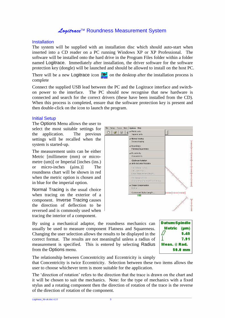
Connect the supplied USB lead between the PC and the Logitrace interface and switch-on power to the interface. The PC should now recognise that new hardware is connected and search for the correct drivers (these have been installed from the CD). When this process is completed, ensure that the software protection key is present and then double-click on the icon to launch the program. Initial Setup The Options Menu allows the user to select the most suitable settings for the application. The previous settings will be recalled when the system is started-up.
The measurement units can be either Metric [millimetre (mm) or micro-metre (um)] or Imperial [inches (ins.) or micro-inches (μins.)] The roundness chart will be shown in red when the metric option is chosen and in blue for the imperial option.
Normal Tracing is the usual choice when tracing on the exterior of a component. Inverse Tracing causes the direction of deflection to be reversed and is commonly used when tracing the interior of a component.
By using a mechanical adaptor, the roundness mechanics can usually be used to measure component Flatness and Squareness. Changing the user selection allows the results to be displayed in the correct format. The results are not meaningful unless a radius of measurement is specified. This is entered by selecting Radius from the Options menu.
The relationship between Concentricity and Eccentricity is simply that Concentricity is twice Eccentricity. Selection between these two items allows the user to choose whichever term is more suitable for the application.
The �direction of rotation� refers to the direction that the trace is drawn on the chart and
it will be chosen to suit the mechanics. Note: for the type of mechanics with a fixed stylus and a rotating component then the direction of rotation of the trace is the reverse of the direction of rotation of the component.
___________________________________________________________________________________________________________________________________________________________________________________________________
Logitrace_hb-uk.doc v1.0 4
When the Shape Compensation option is enabled, the system will apply a mathematical correction to the tracing to correct for shape errors introduced by the component being off-centre. A nominally round but substantially off-centre component will appear to be kidney shaped (this shape is called a limaçon). After the Least Squares centre of the limaçon is found, the system can correct the shape, as it appears on the screen, to restore circularity. If you find that this option is not suitable for your application, you can switch it off.
The Customised Stylus Length option allows the user to use a non-standard length of stylus. When a length is entered, it will be retained by the system until it is changed by the user.
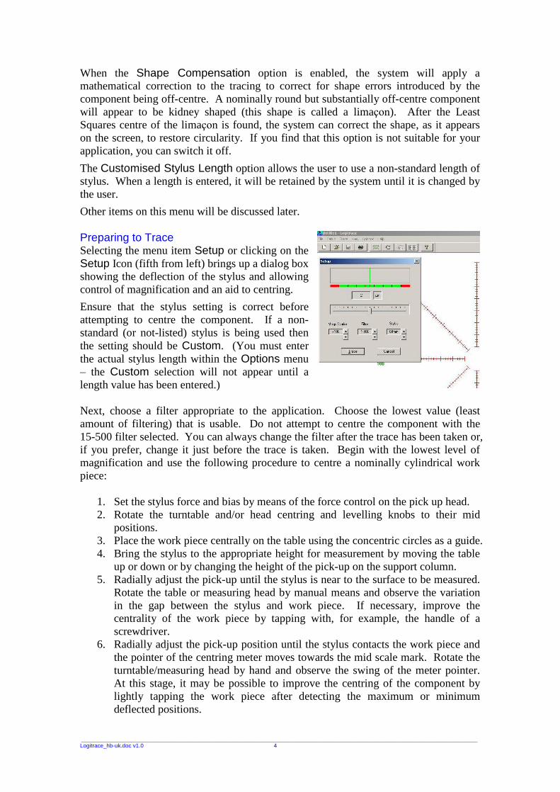
Other items on this menu will be discussed later. Preparing to Trace Selecting the menu item Setup or clicking on the Setup Icon (fifth from left) brings up a dialog box showing the deflection of the stylus and allowing control of magnification and an aid to centring.
Ensure that the stylus setting is correct before attempting to centre the component. If a non-standard (or not-listed) stylus is being used then the setting should be Custom. (You must enter the actual stylus length within the Options menu � the Custom selection will not appear until a length value has been entered.) Next, choose a filter appropriate to the application. Choose the lowest value (least amount of filtering) that is usable. Do not attempt to centre the component with the 15-500 filter selected. You can always change the filter after the trace has been taken or, if you prefer, change it just before the trace is taken. Begin with the lowest level of magnification and use the following procedure to centre a nominally cylindrical work piece:
1. Set the stylus force and bias by means of the force control on the pick up head. 2. Rotate the turntable and/or head centring and levelling knobs to their mid
positions. 3. Place the work piece centrally on the table using the concentric circles as a guide. 4. Bring the stylus to the appropriate height for measurement by moving the table
up or down or by changing the height of the pick-up on the support column. 5. Radially adjust the pick-up until the stylus is near to the surface to be measured.
Rotate the table or measuring head by manual means and observe the variation in the gap between the stylus and work piece. If necessary, improve the centrality of the work piece by tapping with, for example, the handle of a screwdriver.
6. Radially adjust the pick-up position until the stylus contacts the work piece and the pointer of the centring meter moves towards the mid scale mark. Rotate the turntable/measuring head by hand and observe the swing of the meter pointer. At this stage, it may be possible to improve the centring of the component by lightly tapping the work piece after detecting the maximum or minimum deflected positions.

___________________________________________________________________________________________________________________________________________________________________________________________________
Logitrace_hb-uk.doc v1.0 5
7. To refine the centring, bring the stylus position in line with the centring adjustment of the head or table. Using the mechanical adjustments of the machine, bring the centring indicator exactly to the centre position. Then rotate the table/measuring head through 180° and observe the deflection on the
centring meter. Adjust the centring of the table or head to reduce the deflection by half. Move the indicator to the centre of the scale by manually moving the stylus on the column/head or electronically on the computer using the left and right cursor keys.
8. Turn the component/measuring head through 90° and repeat the centring
procedure of section 7. Further refine the centring by this method until the amplitude of the pointer swing is reduced to a minimum.
9. Progressively increase the magnification settings and at each stage, refine the centring if necessary. When the appropriate magnification is reached, or at the point that no further reduction of the amplitude of the pointer swing can be achieved, the work piece is centred as well as roundness will allow and a measurement can be undertaken.
10. If the pointer moves outside the green area (and into the red) then the magnification must be reduced or you must make further attempts to improve the centring.
TIP: You can use the mouse both for controlling electronic centring and for changing magnification. However, it is usually more convenient to use the left and right cursor keys to control centring and the up and down cursor keys to change magnification. When you are satisfied that the component is reasonably centred at the degree of magnification that you wish to use then press the button labelled Trace (or press T).
Note: You can start a trace without using the setup dialog; if, for instance, you are repeating the trace and are sure that the component is centred correctly. Simply select the Trace menu option or click on the Trace icon (fifth from the left). Taking the Trace The screen will show Waiting for Trigger. The trigger is an electronic signal that is generated by the mechanics at the 0 degree point of the trace (this is usually when the mechanics is at the �three o�clock position�). The trigger signal is used for timing and must be seen twice after the Trace command is given before the trace will start to appear. This can take over one minute on slowly moving mechanics.
As soon as the second trigger is seen, the Waiting for Trigger message will change to Reading Data and the trace will start to appear on the screen. Immediately after the trace is completed, the whole screen will be redrawn with the trace shown centrally on the chart according to the reference standard that has been selected � unless the View option Raw Data has been selected (see next section).

___________________________________________________________________________________________________________________________________________________________________________________________________
Logitrace_hb-uk.doc v1.0 6
Examining the Trace You can test the roundness of the traced components against any (or all) of the reference standards. The software will calculate the centre of the trace according to the standard chosen and redraw the trace on the new centre. This causes any undulations or irregularities to appear slightly differently but angles and amplitudes are maintained. If you wish to review the trace as it was taken then you can select Raw Data. In this case no results will be shown.
You can choose to show or not show the Reference Circle and/or Peak & Valley Circles. The system will remember the chosen setting after the software is closed down.
The View menu also provides the facility for showing or not showing the Toolbar (which contains the icon buttons), the Status Bar (which is at the bottom of the screen) and the Digital Meter which only appears within the Setup dialog underneath the deviation pointer.
Other items in the View menu will be discussed later. Examining the Results The results box is displayed whenever the trace is tested against one of the reference standards.
The O symbol represents roundness and is the calculated as the deviation between peak and valley for the measured trace.
The E symbol represents eccentricity and is the displacement between the centre of the reference circle and the datum axis [which is the spindle unless another datum reference has been chosen (see later)]. The E symbol will be replaced by two concentric circles representing concentricity if that option has been chosen (see Initial setup).
The angle symbol represents the value of the angle of a line drawn from Datum to the centre of the reference figure (often referred to as �the angle of eccentricity�).
The arrow symbol represents the run-out which is the total deviation of the gauge as measured from the datum axis. This is independent of the reference standard chosen and will be affected by the accuracy of the component centring as well as the shape or roundness error of the component. The roundness error at any point on the component can be selected and displayed by moving the mouse pointer to a point of interest and clicking the mouse. Alternatively, you can use the left and right cursor keys to move the pointer around the trace. The system takes 1024 measurements around the trace and the pointer will move to the next measurement sample with each depression of the key.
___________________________________________________________________________________________________________________________________________________________________________________________________
Logitrace_hb-uk.doc v1.0 7
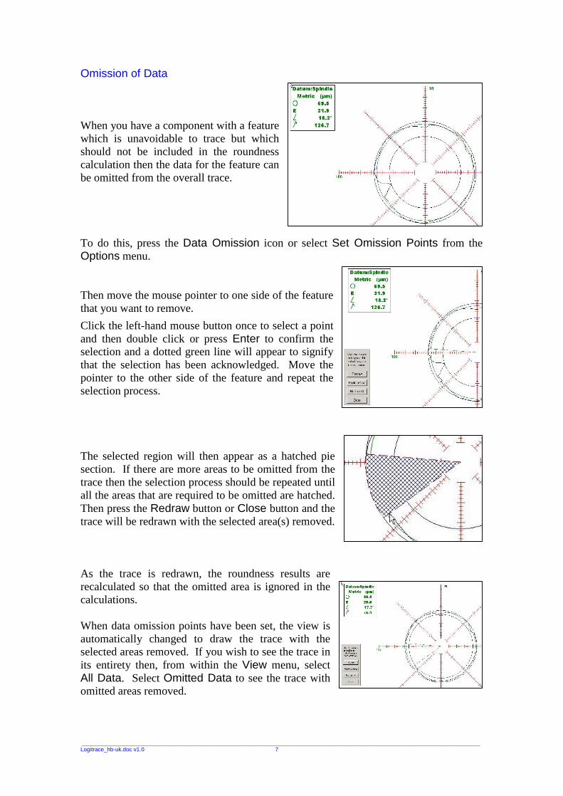
Omission of Data When you have a component with a feature which is unavoidable to trace but which should not be included in the roundness calculation then the data for the feature can be omitted from the overall trace. To do this, press the Data Omission icon or select Set Omission Points from the Options menu. Then move the mouse pointer to one side of the feature that you want to remove.
Click the left-hand mouse button once to select a point and then double click or press Enter to confirm the selection and a dotted green line will appear to signify that the selection has been acknowledged. Move the pointer to the other side of the feature and repeat the selection process. The selected region will then appear as a hatched pie section. If there are more areas to be omitted from the trace then the selection process should be repeated until all the areas that are required to be omitted are hatched. Then press the Redraw button or Close button and the trace will be redrawn with the selected area(s) removed. As the trace is redrawn, the roundness results are recalculated so that the omitted area is ignored in the calculations. When data omission points have been set, the view is automatically changed to draw the trace with the selected areas removed. If you wish to see the trace in its entirety then, from within the View menu, select All Data. Select Omitted Data to see the trace with omitted areas removed.

___________________________________________________________________________________________________________________________________________________________________________________________________
Logitrace_hb-uk.doc v1.0 8
Selecting the Datum The spindle or centre of the turntable is the Datum for the majority of measurements. However, some applications require that one section or part of the component is to be used as the datum or reference point for another nominally concentric section or part. To carry out this measurement, you must first trace the reference section in the normal manner. Ensure that you have selected the appropriate level of magnification and filter and ensure that the appropriate reference standard has been selected from the �View�
menu. If there are areas to be omitted then this may be carried out as described elsewhere. You can save this trace to disc or send to the printer, as you wish. Then, from within the Options menu, select Set Reference Axis. You will be asked �Do you wish to use this trace as datum?� If so, click on Yes. The reference datum is now set for use by a subsequent trace. Carefully move the stylus to the section of interest. Beware if the mechanics is moved in any way, the measurement will not be valid. Take the measurement in the normal manner but avoid making changes to any of the settings. If you find that the pointer moves off the range, you will need to repeat the datum measurement on a lower magnification setting, or repeat after re-centring the component. After completing the trace the results will be shown, as usual, referenced to the Spindle. However, a previously greyed out menu item is now available. If you open the View menu, you will now be able to select Datum: Reference Axis. The display will change, when this item is selected, to show results referenced to the previously defined reference axis. A special symbol of a circle overlaid with a cross indicates the position of the reference axis in relation to the centre of the reference standard circle, which is always positioned at the centre of the chart. This method requires that the component is perfectly aligned to the axis of measurement i.e. square to the table. On some components, it is difficult or even impossible to achieve. In this situation, you can trace two sections of the component and the axis between the centres of these traces can be set as the reference axis. To do this; measure the first reference section as previously described and, from the Options menu, select Set Reference Axis. Then move to the second section and take a trace. Now select Set Upper Axis from the Options menu. You will be asked to enter a Reference Height. This is the distance (in mm.) between the first reference section and this second reference. Now move to the position of interest on the component and take the measurement trace. As previously described, the result will appear on the screen with the spindle as reference. Open the View menu and select Datum: Reference Axis. A new dialog will appear asking you to enter the measurement height. This is the distance (in mm.) from the first reference axis. If you want to change the value entered at a later stage, you can use the Options menu and select Enter Measurement Height.
___________________________________________________________________________________________________________________________________________________________________________________________________
Logitrace_hb-uk.doc v1.0 9
Changing Magnification or Filter You may change the magnification and/or the filter AFTER the trace has been taken. You can use the Options menu and select Change Magnification/Filter Settings or
you can click on the icon.
Be careful not to increase the magnification to such an extent that the trace goes outside of the chart area or the reference circle will not be valid. You can always return to the original settings by pressing the Revert button.
Notes: If the trace went outside of the chart area (into the red area on the setup screen)
when you made the measurement then the results may not be valid. Reducing the magnification without taking a new measurement will not correct for this error.
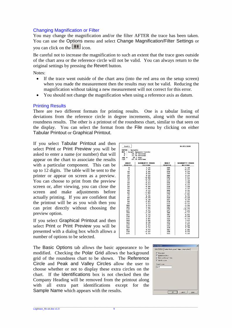
You should not change the magnification when using a reference axis as datum. Printing Results There are two different formats for printing results. One is a tabular listing of deviations from the reference circle in degree increments, along with the normal roundness results. The other is a printout of the roundness chart, similar to that seen on the display. You can select the format from the File menu by clicking on either Tabular Printout or Graphical Printout. If you select Tabular Printout and then select Print or Print Preview you will be asked to enter a name (or number) that will appear on the chart to associate the results with a particular component. This can be up to 12 digits. The table will be sent to the printer or appear on screen as a preview. You can choose to print from the preview screen or, after viewing, you can close the screen and make adjustments before actually printing. If you are confident that the printout will be as you wish then you can print directly without choosing the preview option.
If you select Graphical Printout and then select Print or Print Preview you will be presented with a dialog box which allows a number of options to be selected. The Basic Options tab allows the basic appearance to be modified. Checking the Polar Grid allows the background grid of the roundness chart to be shown. The Reference Circle and Peak and Valley Circles allow the user to choose whether or not to display these extra circles on the chart. If the Identifications box is not checked then the Company Heading will be removed from the printout along with all extra part identifications except for the Sample Name which appears with the results.
___________________________________________________________________________________________________________________________________________________________________________________________________
Logitrace_hb-uk.doc v1.0 10
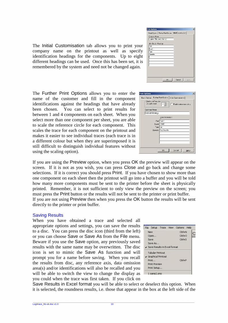
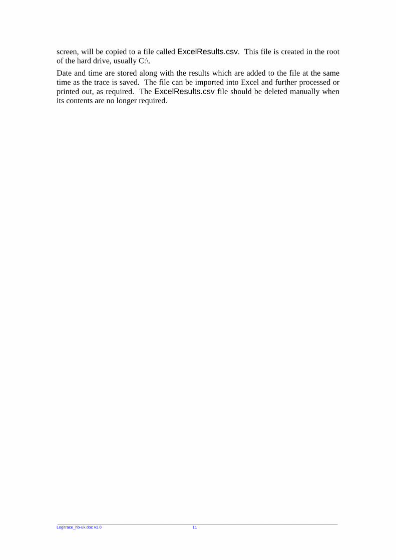
The Initial Customisation tab allows you to print your company name on the printout as well as specify identification headings for the components. Up to eight different headings can be used. Once this has been set, it is remembered by the system and need not be changed again. The Further Print Options allows you to enter the name of the customer and fill in the component identifications against the headings that have already been chosen. You can select to print results for between 1 and 4 components on each sheet. When you select more than one component per sheet, you are able to scale the reference circle for each component. This scales the trace for each component on the printout and makes it easier to see individual traces (each trace is in a different colour but when they are superimposed it is still difficult to distinguish individual features without using the scaling option). If you are using the Preview option, when you press OK the preview will appear on the screen. If it is not as you wish, you can press Close and go back and change some selections. If it is correct you should press Print. If you have chosen to show more than one component on each sheet then the printout will go into a buffer and you will be told how many more components must be sent to the printer before the sheet is physically printed. Remember, it is not sufficient to only view the preview on the screen; you must press the Print button or the results will not be sent to the printer or print buffer. If you are not using Preview then when you press the OK button the results will be sent directly to the printer or print buffer. Saving Results When you have obtained a trace and selected all appropriate options and settings, you can save the results to a disc. You can press the disc icon (third from the left) or you can choose Save or Save As from the File menu. Beware if you use the Save option, any previously saved results with the same name may be overwritten. The disc icon is set to mimic the Save As function and will prompt you for a name before saving. When you recall the results from disc, any reference axis, data omission area(s) and/or identifications will also be recalled and you will be able to switch the view to change the display as you could when the trace was first taken. If you click on Save Results in Excel format you will be able to select or deselect this option. When it is selected, the roundness results, i.e. those that appear in the box at the left side of the
___________________________________________________________________________________________________________________________________________________________________________________________________
Logitrace_hb-uk.doc v1.0 11
screen, will be copied to a file called ExcelResults.csv. This file is created in the root of the hard drive, usually C:\.
Date and time are stored along with the results which are added to the file at the same time as the trace is saved. The file can be imported into Excel and further processed or printed out, as required. The ExcelResults.csv file should be deleted manually when its contents are no longer required.
___________________________________________________________________________________________________________________________________________________________________________________________________
Logitrace_hb-uk.doc v1.0 12
Copyright Logitech Electronics Limited 2008
Document No: Logitrace_hb-uk.doc v1.0 12 February 2008
Warranty Logitrace Interface units carry a two year warranty that is only valid where there is no damage caused by accident, negligence, mis-application, or repairs / modifications attempted by unauthorised personnel. The warranty only extends to the original user.
___________________________________________________________________________________________________________________________________________________________________________________________________
DESIGN & MANUFACTURE OF ELECTRONIC SYSTEMS AND INSTRUMENTATION SUPPLY OF SENSORS AND TRANSDUCERS
121 Trench Road, Trench, Telford, Shropshire, TF2 7DP England tel: +44 (0)1952 677416 fax: +44 (0)1952 605857
e-mail: [email protected] web: www: logitechelectronics.co.uk