
Liquid Leak Detection System - MISA · 2015-03-05 · OPERATION AND MAINTENANCE GUIDE FG-SYS E and...
21
Liquid Leak Detection System OPERATION AND MAINTENANCE GUIDE FG-SYS DIGITAL UNIT TTK UK Ltd. FG-SYS Products: UserGuide_KR_09012001.doc 10.2003 사엔지니어링(주) 서울 강남구 삼성동 44-15 유창빌딩 301호 (우) 135-090 전화 : (02) 543-3495 팩스 : (02) 545-5958 www.misa.co.kr Email: [email protected] January 2001 - Version 1.1
Transcript of Liquid Leak Detection System - MISA · 2015-03-05 · OPERATION AND MAINTENANCE GUIDE FG-SYS E and...

Liquid Leak Detection System
OPERATION AND MAINTENANCE GUIDE
FG-SYS DIGITAL UNIT
TTK UK Ltd. FG-SYS Products: UserGuide_KR_09012001.doc 10.2003
미사엔지니어링(주)서울 강남구 삼성동 44-15유창빌딩 301호(우) 135-090전화 : (02) 543-3495팩스 : (02) 545-5958www.misa.co.kr Email: [email protected]
January 2001 - Version 1.1

OPERATION AND MAINTENANCE GUIDE
FG-SYS E and F
UserGuide_KR_09012001.doc Page 2 on 21
Version 1.1 – January 2001
DESCRIPTION The FG-SYS Digital system ensures an immediate detection and a precise localization of any liquid leak (water, acids, bases, solvents, hydrocarbons) in industrial applications and buildings. The system is composed of a FG-SYS digital unit, lengths of sense cables and accessories. The FG-SYS Digital Unit is designed to be used with sense cables FG-EC (Water and Bases), FG-AC (Acids), or FG-HC2 (Hydrocarbons and Solvents). The presence of a liquid on the sense cable starts an audible alarm, as well as a luminous alert. The information of the fault is displayed on the LCD screen, which specifies the localization of the initial leak point to the nearest metre. Each sense cable is equipped with a microchip at each end. The digital unit questions successively each cable; the microchip then transmits numerically ' the state ' of the cable to the digital unit. Because of autonomy of each cable, several faults can be detected at the same time (but only one fault per cable). A digital unit can manage three circuits of sense cables; each one of these circuits has a maximum capacity of 60 sense cables, 900 metres maximum per circuit. In addition to the presence of a liquid, the system detects and locates any fault of cable break on the circuit of cables. The FG-SYS digital unit is available in rack-mounted version (FG-SYS E), or wall mounted version (FG-SYS F). The keyboard (of twelve buttons) on the front face makes it possible to configure the system: Nominate the zones for detection (by allotting a name to each sense cable), choose and configure for the set-up (relays, serial communication), setting the parameters of the system (language, adjustment of the hour, date, password protection). The green luminous witness, or red, indicates the state of the digital unit under surveillance mode or alarm. The button on the left (situated under the luminous witness) allows the manual acknowledgement of the sound alarm, the validation of an operation, and the return to the previous screen. The last thirty defects are kept in memory and their description is accessible in the Historical menu. FG-SYS also has a general Test function. The digital unit indicates the number of sense cables installed on a circuit, the length of each sense cable, the nominated zones, associated sense cables, as well as the overall length installed. In order to explore the fault information, several tools are available. The FG-SYS Digital unit has eight configurable relays: choose the cables associated with the relay and the type of fault (leak or cable break or both). The FG-SYS has a RS232/RS485 output with a JBUS protocol of communication, or a serial connection, for a link with a printer. The information contained in this document can be the subject to modifications without notice. This information and diagrams were drawn up carefully, however TTK cannot guarantee that the provided information does not contain any error or omission and cannot accept any comparative responsibility with which the information is used. No part of this guide can be reproduced or transmitted without the express and written permission from the Company TTK UK Ltd. FG-SYS is a trademark of TTK S.A.

OPERATION AND MAINTENANCE GUIDE
FG-SYS E and F
UserGuide_KR_09012001.doc Page 3 on 21
Version 1.0 - October 2000
INDEX CERTIFICATIONS I STARTUP OF THE SYSTEM
1. Powering of the FG-SYS Digital Unit 2. Standby Mode
2.1 Name Set Up 2.2 User Interface 2.3 System Set Up
II PROCEDURE OF TEST
1. Function Test 2. Test of Leaks 3. Test of Cable Break 4. Analysis of the Drawing
III MAINTENANCE – FAULTS FINDING
1. Checking the System 2. Maintenance of the System
2.1 Replacement of a sense cable 2.2 Precaution for use and storage 2.3 Addition of sense cables on an existing circuit 2.4 Addition of a new circuit of sense cables
3. Trouble Shooting Guide
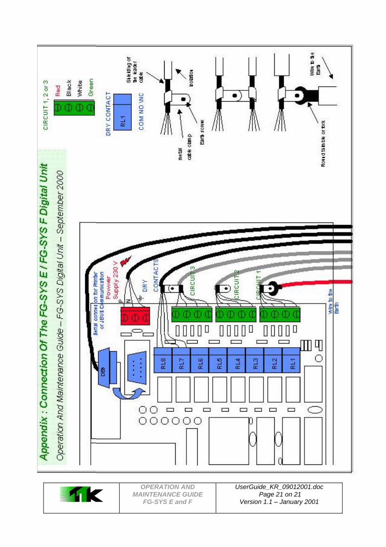
APPENDIX Connection of Digital Unit FG-SYS E / FG-SYS F

OPERATION AND MAINTENANCE GUIDE
FG-SYS E and F
UserGuide_KR_09012001.doc Page 4 on 21
Version 1.0 - October 2000
CERTIFICATIONS Electromagnetic Compatibility E.M.C. FG-SYS E (FROGSYS E) and FG-SYS F (FROGSYS F) are in conformity with the requirements of the generic harmonized European standards: IN 50081-1 (92) for the emissions IN 50082-1 (92) for immunity Report/ratio of tests n° 8080612-CQPE/1 of the 14/09/1998
National laboratory of Tests 1, rue Gaston Boissier 75724 Paris Cedex 15 - France Requirements Safety German FG-SYS E (FROGSYS E) and FG-SYS F (FROGSYS F) are in conformity with the requirements of the German safety requirements IEC 601010-1/A2: 1995 Report/ratio of tests n°01410051446 FG-SYS F: Certificate n° Al 00 08 28525 003 FG-SYS E: Certificate n° B 00 08 28525 004 Date: 08-10-2000 Bauart (B = Bauart) - Gs (Al = Gs)
geprüfteSicherheit
PRODUCT SERVICE
Bauartgeprüft
PRODUCT SERVICE TÜV Product Service GmbH Mergenthalerallee 27 D - 65760 Eschborn

OPERATION AND MAINTENANCE GUIDE
FG-SYS E and F
UserGuide_KR_09012001.doc Page 5 on 21
Version 1.1 – January 2001
I STARTUP OF THE DIGITAL UNIT 1. POWERING OF THE FG-SYS DIGITAL UNIT When all of the cables - leader cables, jumper cables, sense cables, power supply cables - and the accessories – diversion boxes, end termination plugs- are connected, switch the FG-SYS Digital Unit ON. When the digital unit is turned on, it goes into TEST mode: an audible alarm sounds and a luminous witness glows red. The luminous witness turns to green while the digital unit is under TEST, shown on the display. The digital unit tests one circuit after the other. Three circuits of sense cables are available on the digital unit. In the majority of cases, only one circuit is used. The display indicates the length of each sense cable, as well as the overall length of the circuit.
Once the test is finished, the digital unit passes into MONITORING mode:
SYSTEM UNDER TEST VERSION 9908/03
CIRCUITS UNDER TEST CABLE # 1 : 7m COMPUTER ROOM 1 TOTAL CIRCUIT: 7m
on 14/05/2000 15:05 « SITE »
UNDER CONTROL [ H ] isto [ T ] est [ M ] enu
CIRCUITS UNDER TEST CABLE # 2 : 15m COMPUTER ROOM 1 TOTAL CIRCUIT : 22m
CIRCUITS UNDER TEST CABLE # 3 : 7m TGBT TOTAL CIRCUIT: 29m

OPERATION AND MAINTENANCE GUIDE
FG-SYS E and F
UserGuide_KR_09012001.doc Page 6 on 21
Version 1.1 – January 2001
ON 16/03/2000 16:30 « SITE »
UNDER CONTROL [ H ] isto [ T ] est [ M ] enu
2. STANDBY MODE The MENU - accessible by the letter [ M ] - makes it possible to configure the digital unit. To reach it you must type in the password. The initial password is: 1 2 3 4; you will be able to change it in this menu.
[ M ] The sub-menus are displayed once the password has been entered correctly: 2.1. Site Name
1 Þ This sub-menu enables you to define the name of the site, or the digital unit itself, for the use of several digital units within the framework of the same installation.
1 Þ The user has 20 characters for the configuration of the new name.
MENU CONFIGURATION TYPE YOUR PASSWORD : - - - -
MENU CONFIGURATION 1-NAME SETUP 2-USER INTERFACE 3-SYSTEM SETUP
MENU CONFIGURATION 1-NAME SETUP 2-USER INTERFACE 3-SYSTEM SETUP
NAME SETUP : 1-SITE NAME 2-CABLE SETUP
PREVIOUS NAME: SITE NEW NAME : NEW SITE
NAME SETUP : 1-SITE NAME 2-CABLE SETUP

OPERATION AND MAINTENANCE GUIDE
FG-SYS E and F
UserGuide_KR_09012001.doc Page 7 on 21
Version 1.1 – January 2001
2.2. Sense Cables Set Up
1 Þ This sub-menu enables to define zones of detection by gathering under the same name several successive sense cables of the same circuit. By defect, the first cable of the circuit is called:” cable 1”, the second cable is called: “cable 2” and so on, until the end of the circuit. If there is a diversion box, the sense cables downstream from diversion are entered before the last cable of the branch of diversion.
F G -S Y S
c a b le 1
c a b le 2
c a b le 5
c a b le 4
c a b le 3
L e a d e r cab le
E n d term inat ion
The FG-SYS Digital Unit reads the cables on circuit 1. After having recognized all of the sense cables on the first circuit, the menu reads the sense cables on the second circuit and then, those of the third circuit. The length and the name of the first sense cable are registered. By defect, the first sense cable on the first circuit is named: “cable 1”, the second: “cables 2”... The first sense cable of the second circuit is named: “cable 61”, the second: “cables 62”... The first sense cable of the third circuit is named: “cable 121”, the second: “cables 122”... If you do not want to change the name of the cable, move to the following sense cable by pressing the arrow at the bottom of the digital unit.
Press 2 Þ To allot a new name of the first sense cable, choose: “1- CABLE NAME”. Enter the new name, by using the keyboard; to pass to the following letter, use the arrows. You can use 20 characters, which are registered on the line. Validate the configuration by pressing the key under the green led witness.
To validate
MENU CONFIGURATION 1-NAME SETUP 2-USER INTERFACE 3-SYSTEM SETUP
NAME SETUP : 1-SITE NAME 2-CABLENAME
CABLE #1 : 3m ? ? CABLE 1 1-CABLE NAME 2-ASSOCIATE
CABLE #1 : 3m ? ? CABLE 1 NEW NAME : COMPUTER ROOM
CABLE #1 : 3m ? ? COMPUTER ROOM 1-CABLE NAME 2-ASSOCIATE
NAME SETUP : 1-SITE NAME 2-CABLE NAME
OPERATION AND MAINTENANCE GUIDE
FG-SYS E and F
UserGuide_KR_09012001.doc Page 8 on 21
Version 1.1 – January 2001
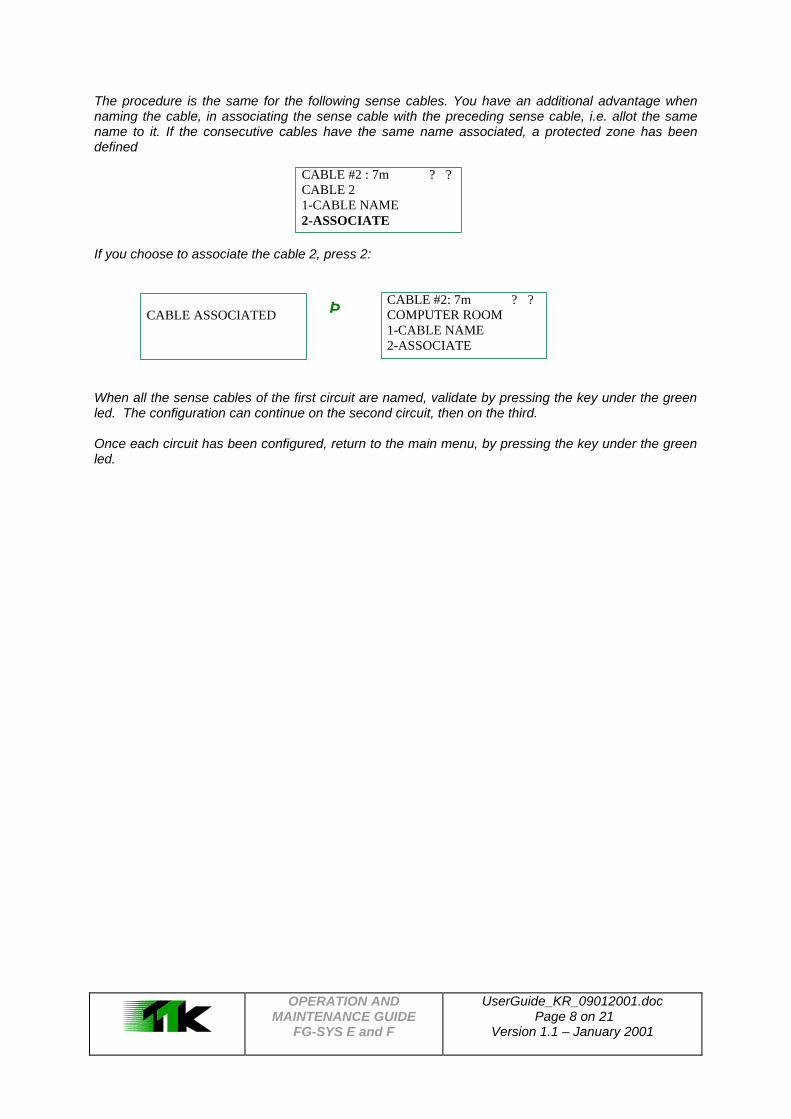
The procedure is the same for the following sense cables. You have an additional advantage when naming the cable, in associating the sense cable with the preceding sense cable, i.e. allot the same name to it. If the consecutive cables have the same name associated, a protected zone has been defined
If you choose to associate the cable 2, press 2:
Þ
When all the sense cables of the first circuit are named, validate by pressing the key under the green led. The configuration can continue on the second circuit, then on the third.
Once each circuit has been configured, return to the main menu, by pressing the key under the green led.
CABLE #2 : 7m ? ? CABLE 2 1-CABLE NAME 2-ASSOCIATE
CABLE ASSOCIATED
CABLE #2: 7m ? ? COMPUTER ROOM 1-CABLE NAME 2-ASSOCIATE

OPERATION AND MAINTENANCE GUIDE
FG-SYS E and F
UserGuide_KR_09012001.doc Page 9 on 21
Version 1.1 – January 2001
2.3. User Interface
This sub-menu enables you to configure the audible alarm ' ON' or ' OFF', to configure the eight relays and to define the mode of communication to use, if available.
2 Þ
Buzzer (Audible alarm)
When the digital unit is configured the audible alarm is set to ON, which you can disconnect.
2 Þ
Relays
You have eight (8)relays, on the chart, via connector blocks. They can be configured into Normally Open (NO) or Normally Closed (NC). You can define the type of fault with which they must be associated - leak, cable break or both . And together for the cables protecting the zone concerned.
1. Relay
The sub-menu allows you to configure relays for general faults. This makes it possible for the User to choose a relay intended for the detection of any type of fault appearing on one of the sense cables or the central processing unit itself, for example leaks, cable breaks, failure of the electronics, in the digital unit, loss of power supply, etc. This dry contact is always configured, normally closed (NC).
1 Þ
The arrows make it possible to choose the relay (from 1 to 8) and the buttons 1 & 0 are respectively used for activating or deactivating the relay concerned. The activation of a relay automatically deactivates another relay configured previously in the general relay sub-menu.
MENU CONFIGURATION 1-NAME SETUP 2-USER INTERFACE 3- SYSTEM SETUP
USER INTERFACE 1-BUZZER ON/OFF 2-RELAYS 3-SERIAL INTERFACE
BUZZER: ON 1-ON 2-OFF
BUZZER: OFF 1-ON 2-OFF
RELAYS: 1-GENERAL 2-LEAK 3-CABLE BREAK
GENERAL FAULT: ? RELAY # 1: OFF 1-ON 0-OFF

OPERATION AND MAINTENANCE GUIDE
FG-SYS E and F
UserGuide_KR_09012001.doc Page 10 on 21
Version 1.1 – January 2001
2. Leak Default Relays
The sub-menu for the relays concerning leaks makes it possible to allocate the faults on one or more of the sense cables. The user is limited to 1 relay per sense cable for this type of fault. If the cables have been associated, all of the cables are automatically programmed to the same relay as the first cable they are associated to.
2 Þ
The arrows make it possible to choose the relay (from 1 to 8)and the buttons 1 and 0 are respectively used for activating or deactivating the dry relay concerned.
1 Þ
Once the relay and its operation has been chosen, the arrows make it possible to choose the sense cables (or the associated cables) to this relay (number 2 in this example). Key 1 activates the cable whose site name is registered, and the configuration passes automatically to the following cable. Key 0 deactivates the relay.
0 Þ To validate
Press the arrow key, on the right hand side to validate the configuration. To validate
If you want to change the configuration of a complex installation, it is recommended to deactivate the relay before starting to associate sense cables to them. This would avoid the possible errors of configuration.
0 Þ
RELAYS: 1-GENERAL 2-LEAK 3-CABLE BREAK
LEAK : ? RELAY # 2 : OFF 1-ON 0-OFF
STATE : RELAY # 2 : 1-NORM. CLOSE 2-NORM. OPEN
LEAK : ? COMPUTER ROOM 1 RELAY # 2 : OFF 1-ON 0-OFF
LEAK : ? TELECOM RELAY # 2 : OFF 1-ON 0-OFF
LEAK : ? TELECOM RELAY # 2 : OFF 1-ON 0-OFF
LEAK : ? RELAY # 2 : ON N.F. 1-ON 0-OFF
RELAYS : 1-GENERAL 2-LEAK 3-CABLE BREAK
LEAK : ? RELAY # 2 : ON N.F. 1-ON 0-OFF
LEAK : ? RELAY # 2 : OFF 1-ON 0-OFF
OPERATION AND MAINTENANCE GUIDE
FG-SYS E and F
UserGuide_KR_09012001.doc Page 11 on 21
Version 1.1 – January 2001
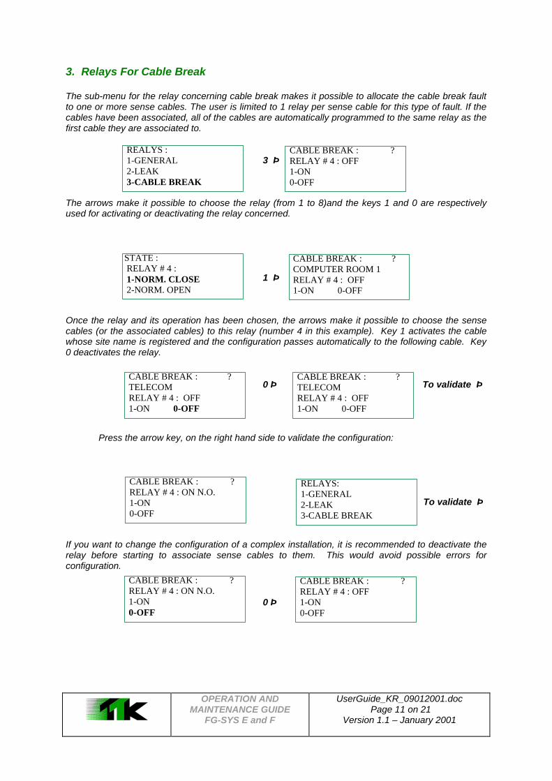
3. Relays For Cable Break
The sub-menu for the relay concerning cable break makes it possible to allocate the cable break fault to one or more sense cables. The user is limited to 1 relay per sense cable for this type of fault. If the cables have been associated, all of the cables are automatically programmed to the same relay as the first cable they are associated to.
3 Þ
The arrows make it possible to choose the relay (from 1 to 8)and the keys 1 and 0 are respectively used for activating or deactivating the relay concerned.
1 Þ
Once the relay and its operation has been chosen, the arrows make it possible to choose the sense cables (or the associated cables) to this relay (number 4 in this example). Key 1 activates the cable whose site name is registered and the configuration passes automatically to the following cable. Key 0 deactivates the relay.
0 Þ To validate Þ
Press the arrow key, on the right hand side to validate the configuration:
To validate Þ
If you want to change the configuration of a complex installation, it is recommended to deactivate the relay before starting to associate sense cables to them. This would avoid possible errors for configuration.
0 Þ
REALYS : 1-GENERAL 2-LEAK 3-CABLE BREAK
CABLE BREAK : ? RELAY # 4 : OFF 1-ON 0-OFF
STATE : RELAY # 4 : 1-NORM. CLOSE 2-NORM. OPEN
CABLE BREAK : ? COMPUTER ROOM 1 RELAY # 4 : OFF 1-ON 0-OFF
CABLE BREAK : ? TELECOM RELAY # 4 : OFF 1-ON 0-OFF
CABLE BREAK : ? TELECOM RELAY # 4 : OFF 1-ON 0-OFF
CABLE BREAK : ? RELAY # 4 : ON N.O. 1-ON 0-OFF
RELAYS: 1-GENERAL 2-LEAK 3-CABLE BREAK
CABLE BREAK : ? RELAY # 4 : ON N.O. 1-ON 0-OFF
CABLE BREAK : ? RELAY # 4 : OFF 1-ON 0-OFF

OPERATION AND MAINTENANCE GUIDE
FG-SYS E and F
UserGuide_KR_09012001.doc Page 12 on 21
Version 1.1 – January 2001
Communication Configuration:
The information provided by the digital unit can be configured in various ways:
1. Serial connection towards a printer with “au fil de l'.eau” printing of the messages for the display
2. Connection JBUS RS232C or RS422 towards an operating system (GTC) 3. The connection is asynchronous. The parameters of the serial connection and protocol JBUS
are as follows:
Electric connections of the DB9: RS232C: 2 - RxD, 3 - TxD, 5 -Mass; RS422: 6 - X-ray -, 7 - Rx+, 8 - Tx -, 9 - Tx+;
Configuration of the serial port: 9600 B, 8 bits of data, 1 bit of stop, s/s parity; Communications protocol: JBUS, function 3 or 4; Number of slave(s): 1 - 99 (configurable); Maximum number of words read: 16 (or 32 bytes); Zone of the defects in the memory: Circuit 1: 61 bytes starting from the addresses 07A0h;
Circuit 2: 61 bytes starting from the addresses 0FA0h; Circuit 3: 61 bytes starting from the addresses 17A0h;
Distribution of the bytes by circuit: 1 byte by sense cable (60 max.) + 1 byte for the catch of termination;
Coding of the defects in the byte: PF(high) pf(low)
Nothing to announce: 0 0 0 0 0 0 0 0; Cable Break: 1 0 0 0 0 0 0 X (0 or 1); Leak: 0 0 0 1 X X X X, where xxxx are the localization of the leak
(0 - 15 m); Format of the answer:
num. Slave function Nb of bytes read byte 1 byte 2... byte N CRC 16 ô 1, 2..., 9 3 or 4 up to 32 XXh XXh ô... XXh XXXXh
Note: The byte of the catch of termination can code only cable break fault;
Warnings:
Caution! When the user uses the response of the digital unit in configuration words, bytes 1, 3, 5, 7, etc… are in the strong weight of the words while bytes 2, 4, 6, 8, etc - in the weak weight.
Caution! The simultaneous use of interfaces RS232 and RS422 causes the outage of the serial communication of the FG-SYS digital unit. It is essential to make sure that the cable connected to connector DB9 uses only the legs used for one of the interfaces: 2, 3 and 5 for RS232C, or 6, 7, 8 and 9 for RS422.

OPERATION AND MAINTENANCE GUIDE
FG-SYS E and F
UserGuide_KR_09012001.doc Page 13 on 21
Version 1.1 – January 2001
These modes of configuration are not set in the origin of the digital unit and so have to be prepared in a particular way.
- It is first of all necessary to indicate the selected mode of communication: exit on a printer or by connection to the JBUS. The activation of a device deactivates the other options automatically.
1 Þ 1 Þ
- Or
3 Þ 1 Þ
The use of connection JBUS requires the configuration of the number of slave: 2 Þ 1 Þ To Indicate the number of slave for JBUS connection, for example 5: 5 Þ to validate
Press arrow key on the right-hand side of the sub-menu (COMMUNICATION SERIES) activates the selected mode of connection.
PRINTER : OFF 1- ON 0 - OFF
SERIAL INTERFACE 1-PRINTER 2-JBUS 3-FROGSURVEILLANCE JBUS SLAVE
PRINTER : ON 1- ON 0 - OFF
FROGSURVEILL. : OFF 1- ON 0 - OFF
SERIAL INTERFACE 1-PRINTER 2-JBUS 3-FROGSURVEILLANCE JBUS SLAVE
FROGSURVEILL. : ON 1- ON 0 - OFF
JBUS : OFF 1- ON 0 - OFF
SERIAL INTERFACE 1-PRINTER 2-JBUS 3-FROGSURVEILLANCE JBUS SLAVE
SLAVE NUMBER : 1 ( 1 – 9 )
SLAVE NUMBER : 5 ( 1 – 9 )
JBUS : ON 1- ON 0 - OFF

OPERATION AND MAINTENANCE GUIDE
FG-SYS E and F
UserGuide_KR_09012001.doc Page 14 on 21
Version 1.1 – January 2001
2.4. Setting the Parameters of the System This sub-menu enables you to choose the language, to set the time, the date and to define a password to access the system for configuration. All these parameters are kept in the memory when the digital unit is switched off.
3 Þ Language: Three languages are available: English, French and German. Adjustment of the hour and date: Enter the time and the date, then validate with the key under the green led witness. Access system: This sub-menu enables you to define a password, which will be necessary during any modification in the configuration.
MENU CONFIGURATION 1-NAME SETUP 2-USER INTERFACE 3-SYSTEM SETUP
SYSTEMSETUP 1-LANGUAGE 2-TIME / DATE SETUP 3-MENU ACCES CODE
LANGUAGE : 1-ENGLISH 2-FRENCH 3-GERMAN
TIME / DATE SETTING: 16:34 15.03.2001
PREVIOUS PASSWORD: 1 2 3 4 NEW CODE : - - - -
CONFIRM NEW PASSWORD:
- - - -

OPERATION AND MAINTENANCE GUIDE
FG-SYS E and F
UserGuide_KR_09012001.doc Page 15 on 21
Version 1.1 – January 2001
II TEST PROCEDURE All the material was installed; you have just turned the FG-SYS digital unit on, it is now necessary to test the system. 1. FUNCTION TEST The digital unit automatically carries out a general test during the powering of the system. This function TEST is also available from the MONITORING mode by pressing the key [T]. An audible alarm sounds and the luminous witness becomes red, it turns green and the display indicates that the circuits are under test. The digital unit tests one circuit after the other. Three circuits of cables are available on the digital unit. In the majority of the cases only one circuit is used. The display indicates the length of each cable, as well as the overall length of all of the circuits. Once the test is finished, the digital unit passes into MONITORING mode: Caution! Each modification on the circuit of cables (change of cable, new provision) forces you to activate the TEST procedure.
CIRCUITS UNDER TEST
CIRCUITS UNDER TEST CABLE # 1 : 7m COMPUTER ROOM 1 TOTAL CIRCUIT : 7m
ON 14/05/2001 15:05 « SITE »
UNDER SURVEILLANCE [ H ] isto [ T ] est [ M ] enu
CIRCUITS UNDER TEST CABLE # 2 : 15m COMPUTER ROOM 1 TOTAL CIRCUIT : 22m
CIRCUITS UNDER TEST CABLE # 3 : 7m TGBT TOTAL CIRCUIT : 29m

OPERATION AND MAINTENANCE GUIDE
FG-SYS E and F
UserGuide_KR_09012001.doc Page 16 on 21
Version 1.1 – January 2001
2. TEST OF LEAK The digital unit is in monitoring mode. Simulate in several areas a leak, in order to check the correct operation of the digital unit. The precision of the localization is ± 1 metre to the leak. Caution! A fault must be present for at least 30/40 seconds before being detected by the digital unit. In the same manner, the digital unit passes again in Standby mode, 30 seconds after the physical suppression of the fault. Put a little water on the sense cable (for example a wet sponge/ clothe etc on the sense cable). Do not put the connector and the black sheath in water! The red luminous witness ignites and a message of leak appears. If a relay is associated to this fault, it rocks. Once the leak has been dried, it takes a few moments, a message appears displaying the end of the fault, the luminous witness becomes green, the relay rocks in to its initial position and the digital unit passes into Standby mode. 3. TEST FOR CABLE BREAK The digital unit is in Standby mode. Disconnect one of the cables, in order to check the correct operation of the digital unit. Remove the termination block situated at the end of the circuit of cables. This will create a cable break at the end of the circuit. The luminous witness passes to the red and a message of cable break appears on the digital unit. If a relay is associated to this fault, it rocks. The precision of localization is ± 1 metre to the fault. Reconnected the end termination plug, a message indicating the end of the fault appears, the luminous witness becomes green, the relay rocks in its initial position and the digital unit passes into standby mode.
LEAK COMPUTER ROOM 1 LOCALIZATION : 58 m 16/04/2001 16:29
CABLE BREAK TELECOM ROOM LOCALIZATION : 7 m 16/04/2001 16:33
END OF FAULT COMPUTER ROOM 1 LOCALIZATION : 58 m 16/04/2001 16:34
END OF FAULT TELECOM ROOM LOCALIZATION : 7 m 16/04/2001 16:41

OPERATION AND MAINTENANCE GUIDE
FG-SYS E and F
UserGuide_KR_09012001.doc Page 17 on 21
Version 1.1 – January 2001
4. Analysis of the Drawing The map is a diagrammatic representation of the architecture of the system, for the detection and localization of leaks from any of the sense cables installed. It indicates the layout of the sense cables, neutral cables, diversion boxes and termination blocks. The use of the drawings is essential for a good explanation of the system for detection, since they make it possible to locate effectively and quickly the fault information indicated by the digital unit. The Laminated drawings are coloured to identify the various cables (detection or neutral), the accessories and the points there has been a simulation of a leak. Two specimens will be provided to you indicating the zones for detection. When several zones are installed on the same level, it is recommended to contemplate a plan of the level. A general drawing can also be carried out to clearly identify the protected zones. Drawing The drawing identifies a series of simulated leaks; the localization of these leaks is displayed on the FG-SYS digital unit. Make a simulation at the remote end of all the sense cables on the circuit. Precisely note the localization given by the digital unit displayed on the LCD panel. It is easier to carry out these simulations with a suitable tool of communication (transmitting - receiver). Simulations concerning leaks must be carried out one after the other in a chronological direction. At the end of the simulations, check if the statements of points are in order with your installation. You can then carry out the drawings, using these statements of points.
CUSTOMER NAME Date: 29-02-2001
FG-SYS E T Branch Box Connector End Termination
Air Conditioning Jumper cable Sense cable FG-EC Sense cable FG-AC
Liquid leak detection system
TELECOMMUNICATION SITE FACILITY
MSC RRrr44411114111R
MSC 2
Telecom Room
1
11
7
30 23
7
1
0
18 20
5
0 15
10 1
5 7
Operator TGBT
FG-SYS E 8
15
22
19 27 25
10
13
15
18
Batteries Room
1 2 3
4 5 67 8 9
0
AB
DE G
H JK MN P
Q TU WX
FROGSYS
FG-SYS Digital Unit
MISA ENG'G

OPERATION AND MAINTENANCE GUIDE
FG-SYS E and F
UserGuide_KR_09012001.doc Page 18 on 21
Version 1.1 – January 2001
III MAINTENANCE – FAULT FINDING 1. CHECKING THE SYSTEM IT IS HIGHLY RECOMMENDED, TO CARRY OUT A COMPLETE MAINTENANCE ON THE FG-SYS TWICE PER ANNUM. THESE TESTS MAKE IT POSSIBLE TO CHECK THE STATE OF THE CIRCUITS, WITH THE SENSE CABLES, AND TO CONTROL THE CORRECT OPERATION OF CENTRAL PROCESSING UNIT FG-SYS E OR FG-SYS F THIS WILL ENSURE A BETTER OPERATION AND RELIABILITY IN TIME, FOR THE SYSTEM. THESE TESTS CAN BE MORE FREQUENTLY CARRIED OUT IN PARTICULARLY EXPOSED ZONES. TO ACTIVATE THE TEST PROCEDURE, AND TO CARRY OUT SIMULATIONS FOR LEAKS AND CABLE-BREAK. REFER TO THE TEST PROCEDURE (CHAPTER IV). - THEN CHECK THE STATE OF THE CLIPS AND THEIR FIXINGS - CHECK THE POSITION OF THE SENSE CABLES AND THEIR PLATING ON THE GROUND. - CHECK THE PRESENCE OF THE LABELS FOR INDICATION ON THE CIRCUITS OF CABLES - CHECK THE CONNECTION OF THE CABLES ON THE DIGITAL UNIT - CHECK THE MECHANICAL AND PHYSICAL STATE OF THE CENTRAL PROCESSING UNIT - CHECK THE EXACTLY THE HOUR AND THE DATE A REPORT/RATIO OF MAINTENANCE MUST BE WRITTEN AFTER EACH INTERVENTION OF MAINTENANCE. COMPANY TTK UK LTD. PROPOSES WITH EACH ONE OF ITS CUSTOMERS A PREVENTIVE MAINTENANCE CONTRACT COMPRISING OF TWO ANNUAL VISITS. 2. MAINTENANCE OF THE SYSTEM FOR ANY HANDLING OF THE CENTRAL PROCESSING UNIT, IT IS IMPERATIVE TO POWER THE SYSTEM DOWN. (TURN IT OFF) 2.1 REPLACEMENT OF A SENSE CABLE The replacement of a sense cable is an easy and fast operation. Disconnect the two ends from the cable and replace it with the new cable. A sense cable must be replaced if it is SHEARED OR CONTAMINATED TOO STRONGLY. THE TRACES OF CONTAMINATION IN WEAK CONCENTRATION ON A SMALL SURFACE CAN BE CLEANED. BEFORE THE REPLACEMENT OF A SENSE CABLE, IT IS NECESSARY TO TURN THE CENTRAL PROCESSING UNIT OFF. FOR REPLACEMENT OF A DETECTINGCABLE, IT IS IMPERATIVE TO ACTIVATE THE TEST PROCEDURE, BY PRESSING ON THE “T” KEY ON THE MAIN KEYPAD. 2.2 PRECAUTIONS FOR USE AND STORAGE THE SENSE CABLE IS MECHANICALLY RESISTANT BUT REMAINS A SENSITIVE CABLE; IT IS NECESSARY TO RESPECT THE FOLLOWING PROCEDURES: - TO PRESERVE THE CABLES IN THEIR CONDITIONING OF ORIGIN IN A CLEAN AND DRY PLACE. - THE INSTALLATION OF THE SENSE CABLES MUST BE CARRIED OUT AFTER OTHER WORKS ON THE BUILDING SITE ARE FINISHED. - TO PROTECT THE CABLES AGAINST ANY RISK FROM SHEARING (FALLS OF HEAVY AND CUTTING TOOLS), ANY CONTACT WITH HEAT SOURCES OR FLAMES (WELDING, GAS-FIRED WARM AIR HEATER...), ANY CONTACT WITH LIQUIDS CONTAMINANT (PAINTING, DETERGENT, CEMENT...) - DURING THE FIXING OF THE CLIPS ON THE GROUND, NOT TO USE ADHESIVE BANDS. THEY ABSORB MOISTURE AND CAN SET OFF ALARMS. - DURING THE FIXING OF THE CLIPS ON THE GROUND, NOT TO USE ADHESIVE BANDS. THEY ABSORB MOISTURE AND CAN SET OFF ALARMS.
OPERATION AND MAINTENANCE GUIDE
FG-SYS E and F
UserGuide_KR_09012001.doc Page 19 on 21
Version 1.1 – January 2001
2.3 ADDITION OF SENSE CABLES ON AN EXISTING CIRCUIT AN EXTENSION OF THE FG-SYS IMPLIES EITHER AN ADDITION OF SENSE CABLES ON A CIRCUIT OF EXISTING CABLES (MAXIMUM CAPACITY OF 60 SENSE CABLES PER CIRCUIT) OR THE INSTALLATION OF A NEW CIRCUIT OF CABLES (CF FOLLOWING PARAGRAPH). IF YOU WANT TO MOVE CABLES, PROCEED IN THE SAME WAY. - TURN THE CENTRAL UNIT OFF - ADD OR MOVE THE DETECTING CABLES - TURN THE CENTRAL UNIT ON (CF III 1.) - CHECK AND MODIFY THE DENOMINATION OF THE CABLES IN THE SMALL MODE (CF III 3.) - FOLLOW THE PROCEDURE OF TEST (CF IV) 2.4 ADDITION OF A NEW CIRCUIT OF SENSE CABLES (CIRCUITS N°2 AND/OR N°3) If the maximum capacity of the existing circuit is reached (60 sense cables), it is necessary to install a circuit of additional cables. That requires the addition of a connecting cable for the circuit. WHEN THE CIRCUIT N°2 IS USED: - REMOVE THE EXISTING SHUNT BETWEEN 2A AND 2B. WHEN THE CIRCUIT N°3 IS USED: - REMOVE THE EXISTING SHUNT BETWEEN 3A AND 3B. CAUTION! A SHUNT BETWEEN ITEMS 1 AND 2 CAUSES A DYSFUNCTION OF THE DIGITAL UNIT. - FOR THE INSTALLATION OF THE CABLES REFER TO CHAPTER II - TURN THE CENTRAL UNIT ON - USE THE SMALL MODE TO NAME THE CABLES - FOLLOW THE TEST PROCEDURE
OPERATION AND MAINTENANCE GUIDE
FG-SYS E and F
UserGuide_KR_09012001.doc Page 20 on 21
Version 1.1 – January 2001
3. TROUBLE SHOOTING GUIDE DURING THE TEST, THE POSTED OVERALL LENGTH NOT CORRESPONDING TO THAT INSTALLED: THERE IS A CABLE DAMAGED ON THE CIRCUIT. IF ONE OF WIRE OF DETECTION (SPIRAL WIRE) IS CUT, THE LENGTH READ BY THE DIGITAL UNIT WILL BE 15 METRES WHATEVER THE REAL LENGTH OF THE CABLE. BUT AS SOON AS THE TEST IS FINISHED, A MESSAGE OF CABLE BREAK INDICATES WHICH IS THE DAMAGED CABLE. DURING THE POWERING THE CABLES INSTALLED ARE NOT READ: TO CHECK THE CONNECTION OF THE CONNECTING CABLE FG-CLC ON THE CONNECTOR BLOCK OF THE DIGITAL UNIT. AN INVERSION BETWEEN THE TWO COUPLES RED + BLACK AND GREEN + WHITE DAMAGES THE ELECTRONICS OF THE FIRST CONNECTED CABLE. DURING THE POWERING THE DIGITAL UNIT DOES NOT READ ONE OF THE CABLES INSTALLED: THE IDENTIFIED CABLE IS PROBABLY DEFECTIVE, AS WELL AS THE CONNECTOR OF THE PRECEDING SENSE CABLE. LEAK IS DETECTED BUT BADLY LOCALISED LIQUID: THE PRECISION OF THE LOCALIZATION OF A LEAK IS + / - 1 METRE. IF A LEAK IS NOT VISIBLE IN THIS PERIMETER, PAY ATTENTION TO THE WHOLE LENGTH OF THE CABLES. THE LEAK CANNOT BE ON THE CABLE UPSTREAM, OR ON THE CABLE DOWNSTREAM; EACH CABLE IS MANAGED IN AN AUTONOMOUS WAY BY A CHIP, PLACED IN ITS CONNECTOR ON THE MALE END WHICH MAKES THEM COMPLETELY INDEPENDANT. MESSAGE OF CABLE BREAK: THE DISPLAY INDICATES THE LOCALIZATION OF A FAULT. CHECK THE CONNECTIONS OF THE CABLE. IF THE LOCALIZATION IS AT THE END OF A LOOP, CHECK THE TERMINATION BLOCK FG-TMC. CHECK FINALLY THE STATE OF THE CABLE OVER ALL ITS LENGTH TO DETECT A CUT OR A SHEARING. CABLE BREAK WITH 0 METER: CHECK THE CONNECTION BETWEEN THE CONNECTING CABLE FG-CLC AND THE CONNECTOR BLOCK ON THE DIGITAL UNIT. A SHORT-CIRCUIT BETWEEN THE RED WIRE AND THE BLACK WIRE CAN CAUSE CABLEBREAK ALARM. MESSAGE OF LEAK WHICH APPEARS AND WHICH DISAPPEARS REGULARLY: THE MESSAGE OF LEAK DOES NOT REMAIN PERMANENTLY REGISTERED. THE THRESHOLD OF CONTAMINATION OF THE CABLE IS NOT REACHED. EITHER THERE IS A SMALL LEAK (INSUFFICIENT TO SET OFF THE ALARM), OR THE CABLE IS POLLUTED (DIRTINESS, PAINTING, GREASE, BITUMINIZE...). THE KEYS OF THE KEYBOARD DO NOT ANSWER ANY MORE: CHECK THE CIRCUIT BOARD ON THE FRONT FACE. IT MAY NOT BE CONNECTED PROPERLY TO THE ELECTRONIC CHART. TO REACH IT, IT IS NECESSARY TO REMOVE THE ELECTRONIC CHART (4 SCREWS). THE AUDIBLE ALARM DOES NOT STOP ANY MORE: IN THE EVENT OF FAULT, THE AUDIBLE ALARM SOUNDS CONTINUOUSLY. IF IT DOES NOT STOP, USE THE MANUAL SWITCH SITUATED UNDER THE GREEN LED WITNESS; CHECK THE CIRCUIT BOARD ON THE FRONT FACE. PROBLEM FROM THE DISPLAY: CONTRAST DECREASES, RETRO-LIGHTING IS IRREGULAR, THE PROBLEM CAN COME FROM THE POWER SOURCE. PLEASE CONTACT TTK. DIGITAL UNIT " BLOCKED ": MAKE A " TEST ", BY PRESSING ON THE “ T “KEY ON THE FRONT KEYPAD. IF AFTER ONE MINUTE THE DIGITAL UNIT IS BLOCKED. TURN THE DIGITAL UNIT OFF, FOR AT LEAST THREE MINUTES, THEN TURN IT ON. IF STILL NO RESPONSE CALL TTK
OPERATION AND MAINTENANCE GUIDE
FG-SYS E and F
UserGuide_KR_09012001.doc Page 21 on 21
Version 1.1 – January 2001